1
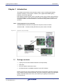
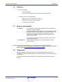
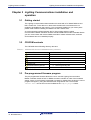
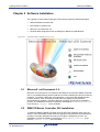
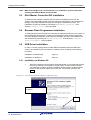
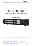
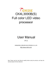
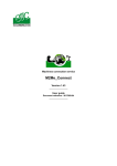
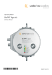
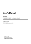
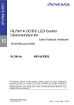
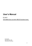
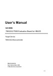
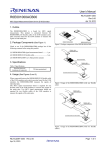
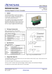
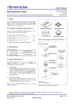
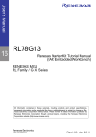
User’s Manual
Lighting Communications
8
Demonstration Board for Lighting
communication data protocols
All information contained in these materials, including products and product specifications,
represents information on the product at the time of publication and is subject to change by
Renesas Electronics Corp. without notice. Please review the latest information published by
Renesas Electronics Corp. through various means, including the Renesas Technology Corp.
website (http://www.renesas.com).
www.renesas.com
R20UT0919ED0100, Rev. 1.00
December 19, 2011
Notice
1. All information included in this document is current as of the date this document is issued. Such information, however, is subject to
change without any prior notice. Before purchasing or using any Renesas Electronics products listed herein, please confirm the latest
product information with a Renesas Electronics sales office. Also, please pay regular and careful attention to additional and different
information to be disclosed by Renesas Electronics such as that disclosed through our website.
2. Renesas Electronics does not assume any liability for infringement of patents, copyrights, or other intellectual property rights of third
parties by or arising from the use of Renesas Electronics products or technical information described in this document. No license,
express, implied or otherwise, is granted hereby under any patents, copyrights or other intellectual property rights of Renesas
Electronics or others.
3. You should not alter, modify, copy, or otherwise misappropriate any Renesas Electronics product, whether in whole or in part.
4. Descriptions of circuits, software and other related information in this document are provided only to illustrate the operation of
semiconductor products and application examples. You are fully responsible for the incorporation of these circuits, software, and
information in the design of your equipment. Renesas Electronics assumes no responsibility for any losses incurred by you or third
parties arising from the use of these circuits, software, or information.
5. When exporting the products or technology described in this document, you should comply with the applicable export control laws and
regulations and follow the procedures required by such laws and regulations. You should not use Renesas Electronics products or the
technology described in this document for any purpose relating to military applications or use by the military, including but not limited
to the development of weapons of mass destruction. Renesas Electronics products and technology may not be used for or
incorporated into any products or systems whose manufacture, use, or sale is prohibited under any applicable domestic or foreign
laws or regulations.
6. Renesas Electronics has used reasonable care in preparing the information included in this document, but Renesas Electronics does
not warrant that such information is error free. Renesas Electronics assumes no liability whatsoever for any damages incurred by you
resulting from errors in or omissions from the information included herein.
7. Renesas Electronics products are classified according to the following three quality grades: "Standard", "High Quality", and "Specific".
The recommended applications for each Renesas Electronics product depends on the product's quality grade, as indicated below.
You must check the quality grade of each Renesas Electronics product before using it in a particular application. You may not use any
Renesas Electronics product for any application categorized as "Specific" without the prior written consent of Renesas Electronics.
Further, you may not use any Renesas Electronics product for any application for which it is not intended without the prior written
consent of Renesas Electronics. Renesas Electronics shall not be in any way liable for any damages or losses incurred by you or third
parties arising from the use of any Renesas Electronics product for an application categorized as "Specific" or for which the product is
not intended where you have failed to obtain the prior written consent of Renesas Electronics.
The quality grade of each Renesas Electronics product is “Standard” unless otherwise expressly specified in a Renesas Electronics
data sheets or data books, etc.
“Standard”:
Computers; office equipment; communications equipment; test and measurement equipment; audio and visual
equipment; home electronic appliances; machine tools; personal electronic equipment; and industrial robots.
“High Quality”:
Transportation equipment (automobiles, trains, ships, etc.); traffic control systems; anti-disaster systems; anticrime systems; safety equipment; and medical equipment not specifically designed for life support.
“Specific”:
Aircraft; aerospace equipment; submersible repeaters; nuclear reactor control systems;medical equipment or
systems for life support (e.g. artificial life support devices or systems), surgical implantations, or healthcare
intervention (e.g. excision, etc.), and any other applications or purposes that pose a direct threat to human life.
8. You should use the Renesas Electronics products described in this document within the range specified by Renesas Electronics,
especially with respect to the maximum rating, operating supply voltage range, movement power voltage range, heat radiation
characteristics, installation and other product characteristics. Renesas Electronics shall have no liability for malfunctions or damages
arising out of the use of Renesas Electronics products beyond such specified ranges.
9. Although Renesas Electronics endeavors to improve the quality and reliability of its products, semiconductor products have specific
characteristics such as the occurrence of failure at a certain rate and malfunctions under certain use conditions. Further, Renesas
Electronics products are not subject to radiation resistance design. Please be sure to implement safety measures to guard them
against the possibility of physical injury, and injury or damage caused by fire in the event of the failure of a Renesas Electronics
product, such as safety design for hardware and software including but not limited to redundancy, fire control and malfunction
prevention, appropriate treatment for aging degradation or any other appropriate measures. Because the evaluation of microcomputer
software alone is very difficult, please evaluate the safety of the final products or system manufactured by you.
10. Please contact a Renesas Electronics sales office for details as to environmental matters such as the environmental compatibility of
each Renesas Electronics product. Please use Renesas Electronics products in compliance with all applicable laws and regulations
that regulate the inclusion or use of controlled substances, including without limitation, the EU RoHS Directive. Renesas Electronics
assumes no liability for damages or losses occurring as a result of your noncompliance with applicable laws and regulations.
11. This document may not be reproduced or duplicated, in any form, in whole or in part, without prior written consent of Renesas
Electronics.
12. Please contact a Renesas Electronics sales office if you have any questions regarding the information contained in this document or
Renesas Electronics products, or if you have any other inquiries.
(Note 1) "Renesas Electronics" as used in this document means Renesas Electronics Corporation and also includes its majorityowned subsidiaries.
(Note 2) "Renesas Electronics product(s)" means any product developed or manufactured by or for Renesas Electronics.
General Precautions for Handling This Product
1. Circumstances not covered by product guarantee
•
If the product was disassembled, altered, or repaired by the customer
•
If it was dropped, broken, or given another strong shock
•
Use at overvoltage, use outside guaranteed temperature range, storing outside guaranteed
temperature range
•
If the cable of the power adapter, the USB interface cable or the like was bent or pulled excessively
•
If a power adapter other than the supplied product was used
•
If the product got wet
•
If this product is connected to the target system when there is a potential difference between the GND
of this product and GND of the target system.
•
If the connectors or cables are plugged/unplugged while this product is in the power-on state.
•
If excessive load is applied to the connectors or sockets
•
If a metal part of the power connection, or another such part comes in contact with an electrostatic
charge.
•
If the product is used or stored in an environment where an electrostatic or electrical noise is likely to
occur.
2. Safety precautions
•
Parts of board can become hot during operation!
•
Do not look into the LEDs directly; doing so may cause weakening eyesight!
•
Be careful of electrical shock. There is a danger of electrical shock if the product is used as described
above in 1. Circumstances not covered by product guarantee.
•
The power adapter supplied with the product is exclusively for this product, so do not use it with other
products.
78K0/Ix2 LED Control
Table of Contents
Chapter 1
1.1
1.2
1.3
1.4
Introduction...........................................................................................5
Package contents ....................................................................................................................5
Features ...................................................................................................................................6
System requirements ...............................................................................................................6
Trademarks ..............................................................................................................................6
Chapter 2
2.1
2.2
Hardware ...............................................................................................7
2.2.1
2.2.2
2.2.3
2.2.4
Power supply ...........................................................................................................................7
Switch settings .........................................................................................................................8
SW1 (IR remote control)....................................................................................................8
SW2 (IR remote signal send) ............................................................................................8
SW3 (DMX512 mode select)..............................................................................................8
SW4 (Operation mode select)...........................................................................................8
Switch setting for communication protocol evaluation.............................................................8
DMX512 Interface ....................................................................................................................9
Chapter 3
Lighting Communications installation and operation .....................10
2.3
2.4
3.1
3.2
3.3
Getting started .......................................................................................................................10
CD-ROM contents..................................................................................................................10
Pre-programmed firmware program ......................................................................................10
Chapter 4
Hardware Installation..........................................................................11
Chapter 5
Software Installation...........................................................................12
5.1
5.2
5.3
5.4
5.5
Microsoft .net Framework 3.5 ................................................................................................12
DMX512 Master Controller GUI installation...........................................................................12
DALI Master Controller GUI installation.................................................................................13
Renesas Flash Programmer installation................................................................................13
USB Driver Installation...........................................................................................................13
5.5.1
Installation on Windows XP............................................................................................13
5.5.2
Installation on Windows 7 ..............................................................................................16
Chapter 6
DMX512 Master Controller GUI..........................................................22
Chapter 7
DALI Master Controller GUI ...............................................................23
R20UT0919ED0100 Rev. 1.10
14. November 2011
Page 4 of 27
Lighting Communications
Introduction
Chapter 1 Introduction
This board can be used as communication master in case controlling each lighting
evaluation board by communication. DMX512, DALI (digital addressable lighting
interface), and IR are supported.
Each lighting evaluation board can be controlled via this communication master board by
using a GUI program. Control GUI programs for DALI and DMX512 are available on the
CD-ROM included in this demonstration kit. This board is using USB bus power for its
operation.
Note: Following boards can be controlled
78K0/IB2 HBLED Evaluation board (EZ-LED1-002) Part number: EZ-0005
78K0/IA2 PWM
Evaluation board (EZ-LED2-001) Part number: EZ-0006
Figure 1-1 System setup example
1.1
Package contents
•
Lighting Communication Master Evaluation board (EZ-0008)
•
USB cable
•
One set of plastic stands and screws
•
CD-ROM with DALI and DMX512 Master Control GUI software
Please verify that you have received all parts listed in the package contents list attached
to the Lighting Communications package. If any part is missing or seems to be damaged,
please contact the dealer from whom you received your Lighting Communications
demonstration kit.
R20UT0919ED0100 Rev. 1.10
14. November 2011
Page 5 of 27
Lighting Communications
1.2
Features
•
•
1.3
Introduction
USB power supply.
o
5V supply voltage
o
15V for DALI communication generated by switching regulator
3 kinds of operation mode supported
o
DMX512 protocol communication interface
o
DALI protocol communication interface
o
IR remote control interface
System requirements
HOST PC
Host interface
A PC supporting Windows XP (32bit), Windows Vista (32bit) or
Windows 7 (32bit) is required.
A Pentium processor with at least 1 GHz CPU performance, with
at least 256 Mbytes of RAM, allowing you to fully utilize and take
advantage of the product features. 500 Mbytes of free disk
space and an additional 10 Mbytes of free disk space on the
Windows system drive.
A web browser and Adobe Reader to be able to access all the
product documentation.
USB interface that enables communication based on USB
(Ver1.1 or later)
Note: Updates of the GUI programs, documentation and/or utilities for the Lighting
Communications demonstration Kit, if available, may be downloaded from the Renesas
WEB page(s) at http://www.renesas.eu/78K0-LIGHTCOMMS
1.4
Trademarks
Microsoft, Windows and HyperTerminal are registered trademarks of Microsoft
Corporation. Adobe and Acrobat Reader are registered trademarks of Adobe Systems
Incorporated.
All other product names are trademarks or registered trademarks of their respective
owners.
R20UT0919ED0100 Rev. 1.10
14. November 2011
Page 6 of 27
Lighting Communications
Lighting Communications installation and operation
Chapter 2 Hardware
This chapter describes the specification of Lighting Communication Master Evaluation
Board (EZ-0008) delivered with the Lighting Communications demonstration kit.
The Lighting Communications demonstration kit is assembled with a Renesas
µPD78F0503DA 8-bit microcontroller and connectors for DALI and DMX512 as well as
an IR diode for IR communication.
Figure 2-1 Appearance of Lighting Communication Master Evaluation Board (Top View)
Figure 2-2 Appearance of Lighting Communication Master Evaluation Board (Bottom View)
2.1
Power supply
The following AC adaptor or dc power supplier is recommended to be applied to the
Lighting Communication Master Evaluation board via the Switchcraft RAPC722 (Center
pin f 1.93mm, Plug f 6.3mm (max) connector.
Figure 2-3 Polarity and shape of DC plug
R20UT0919ED0100 Rev. 1.10
14. November 2011
Page 7 of 27
Lighting Communications
•
Lighting Communications installation and operation
DC power supplier
Output voltage: 15 V
Connector:
refer to figure 2-3
Note: Use DC adapter adapted to safety standard of each country.
2.2
Switch settings
Different switches are assembled to the Lighting Communication Master Evaluation
Board to set up the wanted communication mode. The functionality of these switches is
described below.
2.2.1 SW1 (IR remote control)
With SW1 the IR remote control code is chosen.
Table 2-1 SW1 settings
Position
Communication protocol
CH1
DMX512 interface
CH2
DALI interface
2.2.2 SW2 (IR remote signal send)
SW2 is a push button to send the selected IR remote signal.
2.2.3 SW3 (DMX512 mode select)
SW3 enables or disables the DMX512 communication operation.
Table 2-2 SW3 settings
Position
Communication protocol
DMX512
Enable DMX512 communication operation
Wireless
Disable DMX512 communication operation
2.2.4 SW4 (Operation mode select)
With SW4 the wanted operation mode can be selected.
Table 2-3 SW4 settings
Position
2.3
Communication protocol
RUN
Enable communication operation
Write
Disable communication operation
Reserved for USB microncontroller firmware updating
Switch setting for communication protocol evaluation
SW3 and SW4 have to be set to following settings for the regarding communication
protocols.
R20UT0919ED0100 Rev. 1.10
14. November 2011
Page 8 of 27
Lighting Communications
Lighting Communications installation and operation
Table 2-4 SW4 settings
Communication protocol
DMX512 protocol
2.4
SW3
SW4
DMX
RUN
DALI protocol
Don’t care
RUN
IR protocol
Don’t care
RUN
DMX512 Interface
The Lighting Communication Master evaluation board provides a DMX512 connector to
communicate with other hardware via the DMX512 communication standard. Therefore
the connector is connected to the UART0 interface of the µPD78F0503DA
microcontroller via the SW3 switch.
Table 2-5 DMX512 Connectors
Pin Number
1
R20UT0919ED0100 Rev. 1.10
14. November 2011
Communication protocol
Ground
2
D+
3
D-
Page 9 of 27
Lighting Communications
Lighting Communications installation and operation
Chapter 3 Lighting Communications installation and
operation
3.1
Getting started
The Lighting Communications demonstration kit comes with a PC based DMX512 and
DALI master GUI. To be able to run these tools the Microsoft .net framework 3.5 is
needed to be installed on the host PC. If it is not already installed on your host system
please install it before installing the DMX512 or DALI master GUIs.
As communication interface between the PC host system and the Lighting
Communication Master evaluation board a standard USB interface line is needed. Before
you can communicate with via the DMX512 and DALI master software tools, software
and hardware have to be installed properly.
3.2
CD-ROM contents
The CD-ROM shows following directory structure:
Table 3-1 78K0/Ix2 LED Control CD-ROM directory structure
78K0IX2-LED
3.3
CD-ROM ROOT
Acrobat
1.
Acrobat Reader for 32Bit Windows OS
Doc
2.
Documentation
dotnet
3.
Microsoft .net package
Driver
4.
78K0/Ix2 LED Control USB driver files
Master tools
5.
GUI programs for DALI and DMX512
Renesas Flash Programmer
6.
Flash Programming GUI
sample program
7.
Master control firmware
Pre-programmed firmware program
The pre-programmed firmware allows the user to use this Lighting Communication
Master evaluation board as DALI or DMX512 master controller in order of the hardware
setting chosen. If the firmware is damaged or erased by mistake from the device it can be
programmed again by using the Renesas Flash Programmer GUI. The firmware
“master.hex” can be found on the CD-ROM in the sample program folder.
R20UT0919ED0100 Rev. 1.10
14. November 2011
Page 10 of 27
78K0/Ix2 LED Control
Hardware Installation
Chapter 4 Hardware Installation
After unpacking the Lighting Communications Starter kit, connect the board via the USB
connector to your host computer using the provided USB interface cable. When Lighting
Communication Master evaluation board is connected, the USB driver needs to be
installed on the host machine. Please refer to the following Chapter 5 Software
Installation.
R20UT0919ED0100 Rev. 1.10
14. November 2011
Page 11 of 27
Lighting Communications
Software Installation
Chapter 5 Software Installation
The Lighting Communications package comes with the following software packages:
•
DMX512 Master Controller GUI
•
DALI Master Controller GUI
•
Microsoft .net Framework 3.5
•
Renesas Flash Programmer GUI including the PRM file for µPD78F0503
Figure 5-1 78K0IX2-LED CDROM autorun.exe
5.1
Microsoft .net Framework 3.5
Microsoft .net Framework 3.5 is needed for the DMX512 and the DALI Master Controller
GUI. If not installed already please install this tool before installing the above mentioned
programs. To install the Microsoft .net Framework 3.5 just press the regarding button
from the Autorun of the CD-ROM provided within the Lighting Communications
demonstration kit package. The setup dialogue will guide you through the installation
process. The installation can also be started by executing the dotNetFx35setup.exe
in the directory “\dotnet” of the CD-ROM.
5.2
DMX512 Master Controller GUI installation
To install the DMX512 Master Controller GUI just press the regarding button from the
Autorun of the CD-ROM provided within the Lighting Communications demonstration kit
package. The setup dialogues will guide you through the installation process. The
installation can also be started by executing the DMX512MCGUI_V100E.msi in the
directory “\Master tools” of the CD-ROM.
R20UT0919ED0100 Rev. 1.10
14. November 2011
Page 12 of 27
Lighting Communications
Software Installation
Note: Make sure that Microsoft .net Framework 3.5 is installed on your host PC before
installing the DMX512 Master Controller GUI.
5.3
DALI Master Controller GUI installation
To install the DALI Master Controller GUI just press the regarding button from the
Autorun of the CD-ROM provided within the Lighting Communications demonstration kit
package. The setup dialogues will guide you through the installation process. The
installation can also be started by executing the DALIMCGUI_V100E.msi in the
directory “\Master tools” of the CD-ROM.
5.4
Renesas Flash Programmer installation
To install Renesas Flash Programmer just press the regarding button from the Autorun of
the CD-ROM provided within the Lighting Communications demonstration kit package.
The setup dialogues will guide you through the installation process. The installation can
also be started by executing the RFP-EE_V10200.exe in the directory ”\Renesas
Flash Programmer” of the CD-ROM.
5.5
USB Driver Installation
In order to use the Lighting Communication Master evaluation board the USB driver
needs to be installed on the host machine. Install the driver according to the following
procedure:
Installation on Windows XP
Page 13
Installation on Windows 7
Page 16
5.5.1 Installation on Windows XP
1.
When the Lighhting Communications evaluation board is connected with the host
machine, the board is recognized by Plug and Play, and the wizard for finding
new hardware is started. At first the hardware wizard will ask if windows should
search on the windows update web, check "No, not this time" and then click
Next>.
Figure 5-4 Found New Hardware Wizard 1 (Windows XP)
Check that "No, not this time"
is selected.
Click.
R20UT0919ED0100 Rev. 1.10
14. November 2011
Page 13 of 27
Lighting Communications
Software Installation
2.
Check that "Install from a list or specific location (Advanced)" is selected, then
click Next>.
Figure 5-5 Found New Hardware Wizard 2 (Windows XP)
Check that "Install from a list or
specific ..." is selected.
3.
Click.
Check that "Search for the best driver in these locations." is selected. Select the
"Include this location in the search:" check box and then click Browse.
Figure 5-6 Search Location Specification 1 (Windows XP)
<1> Check that "Search
for the best driver in
these locations." is
selected.
<2> Check "Include this
location
in
the
search:" only.
<3> Click.
4.
R20UT0919ED0100 Rev. 1.10
14. November 2011
Locate the folder "C CDROM:\Driver” and click OK.
Page 14 of 27
Lighting Communications
Software Installation
Figure 5-7 Search Location Specification 2 (Windows XP)
5.
After the installation of the USB driver is completed the window below is
displayed. Click Finish to close the hardware wizard.
Figure 5-8 USB Driver Installation Completion (Windows XP)
6.
After installing the USB driver, check that the driver has been installed normally,
according to the procedure below. When using the Lighting Communications
evaluation board the “Renesas Electronics Starter Kit Virtual UART” should be
present like in the figure below.
Please check in the Windows "Device Manager" within the Windows Properties
(“Hardware” tab), that the driver is installed normally.
R20UT0919ED0100 Rev. 1.10
14. November 2011
Page 15 of 27
Lighting Communications
Software Installation
Figure 5-9 Device Manager driver correctly installed (Windows XP)
5.5.2 Installation on Windows 7
When the Lighting Communications evaluation board is connected with the host machine,
the board is recognized by Plug and Play, and the wizard for finding new hardware is
started. When firstly installing a Renesas Demonstration Kit, that uses the Virtual COM
port driver, the automatic installation will fail. Therefore the USB driver has to be installed
manually. To do so please follow the instructions below:
1.
R20UT0919ED0100 Rev. 1.10
14. November 2011
Press the Start Button and type “Device Manager” into the text box. Select the
Device Manager from the available search results
Page 16 of 27
Lighting Communications
Software Installation
Figure 5-10 Open device manager (Windows 7)
2.
The Lighting Communications evaluation board is listed as “Unknown device”.
Right click on the “Unknown device” entry and select “Update driver”.
Figure 5-11 Locate Device to manually install USB driver (Windows 7)
Right
Click.
R20UT0919ED0100 Rev. 1.10
14. November 2011
Page 17 of 27
Lighting Communications
3.
Software Installation
Select “Browse my computer for driver software” to locate and install the driver
software manually
Figure 5-12 Select driver search method (Windows 7)
Click.
4.
Click Browse to locate the USB driver location.
Figure 5-13 Search Location Specification 1 (Windows 7)
Click.
R20UT0919ED0100 Rev. 1.10
14. November 2011
Page 18 of 27
Lighting Communications
5.
Software Installation
Locate the folder "CDROM:\Driver” and click OK.
Figure 5-14 Search Location Specification 2 (Windows 7)
6.
Press Next when the correct search path is inserted in the “Search for driver in
this location:” field.
Figure 5-15 Search Location Specification 3 (Windows 7)
Click.
7.
R20UT0919ED0100 Rev. 1.10
14. November 2011
Based on the Windows 7 security settings the “Would you like to install this
device software” dialogue can pop up. If so press Install.
Page 19 of 27
Lighting Communications
Software Installation
Figure 5-16 Windows security information (Windows 7)
Click.
8.
After the installation of the USB driver is completed the window below is
displayed. Click Close to close the hardware wizard.
Figure 5-17 USB driver installation completion (Windows 7)
9.
R20UT0919ED0100 Rev. 1.10
14. November 2011
After installing the USB driver, check that the driver has been installed normally,
according to the procedure below. When using the Lighting Communications
evaluation board the “Renesas Electronics Starter Kit Virtual UART” should be
present like in the figure below.
Page 20 of 27
Lighting Communications
DMX512 Master Controller GUI
Figure 5-18 Device Manager driver correctly installed (Windows 7)
R20UT0919ED0100 Rev. 1.10
14. November 2011
Page 21 of 27
Lighting Communications
DMX512 Master Controller GUI
Chapter 6 DMX512 Master Controller GUI
In this chapter you will find a description how to set up the hardware settings to be able to
use the DMX512 Master Controller GUI. For further information how to use the software
tool please refer to the DMX512 Master Controller GUI User’s manual
(U19596EJ1V0UM00.pdf) in the “\Doc” folder of the delivered CD-ROM.
1. Make sure that SW4 is on “RUN” and SW3 on “DMX” side
2. Connect the lighting communication master evaluation board with DMX512 slave
board or your own evaluation board supporting DMX512 protocol via interface J1.
3. Connect lighting communication master evaluation board with PC by a USB cable.
Figure 6-1 DMX interface connector
4. Insert power supply to the slave board.
5. Send DMX512 codes to slaves by DMX512 Master Controller GUI or your own
software.
6. Disconnect the DC power of slave board.
7. Disconnect the lighting communication master evaluation board and the host PC.
8. Disconnect the lighting communication master evaluation board and the slave board.
When using a communication line longer than 1m, a twisted pair wire is recommended to
be used for the ‘+’ and ‘-‘ lines.
Note: Do not plug or unplug a connector or cable while power is applied to the board.
R20UT0919ED0100 Rev. 1.10
14. November 2011
Page 22 of 27
Lighting Communications
DALI Master Controller GUI
Chapter 7 DALI Master Controller GUI
In this chapter you will find a description how to set up the hardware settings to be able to
use the DALI Master Controller GUI. For further information how to use the software tool
please refer to the DALI Master Controller GUI User’s manual
(U19607EJ1V1UM00.pdf) in the “\Doc” folder of the CD-ROM.
1. Confirm SW4 is set to “RUN” side.
2. Connect the lighting communication master evaluation board (EZ-0008) with DALI
slave board or your own evaluation board supporting DALI protocol via interface J4.
Figure 7-1 DALI interface connector
3. Connect lighting communication master evaluation board with PC by a USB cable
4. Insert power supply to the slave board.
5. Send DALI codes to slaves by DALI Master Controller GUI or your own software.
6. Disconnect the DC power of slave board.
7. Disconnect the lighting communication master evaluation board and the host PC.
8. Disconnect the lighting communication master evaluation board and the slave board.
Note: Do not plug or unplug a connector or cable while power is applied to the board.
R20UT0919ED0100 Rev. 1.10
14. November 2011
Page 23 of 27
[MEMO]
Lighting Communications User’s Manual
Publication Date:
Published by:
Rev.1.01
Dec 19, 2011
Renesas Electronics Corporation
http://www.renesas.com
SALES OFFICES
Refer to "http://www.renesas.com/" for the latest and detailed information.
Renesas Electronics America Inc.
2880 Scott Boulevard Santa Clara, CA 95050-2554, U.S.A.
Tel: +1-408-588-6000, Fax: +1-408-588-6130
Renesas Electronics Canada Limited
1101 Nicholson Road, Newmarket, Ontario L3Y 9C3, Canada
Tel: +1-905-898-5441, Fax: +1-905-898-3220
Renesas Electronics Europe Limited
Dukes Meadow, Millboard Road, Bourne End, Buckinghamshire, SL8 5FH, U.K
Tel: +44-1628-585-100, Fax: +44-1628-585-900
Renesas Electronics Europe GmbH
Arcadiastrasse 10, 40472 Düsseldorf, Germany
Tel: +49-211-65030, Fax: +49-211-6503-1327
Renesas Electronics (China) Co., Ltd.
7th Floor, Quantum Plaza, No.27 ZhiChunLu Haidian District, Beijing 100083, P.R.China
Tel: +86-10-8235-1155, Fax: +86-10-8235-7679
Renesas Electronics (Shanghai) Co., Ltd.
Unit 204, 205, AZIA Center, No.1233 Lujiazui Ring Rd., Pudong District, Shanghai 200120, China
Tel: +86-21-5877-1818, Fax: +86-21-6887-7858 / -7898
Renesas Electronics Hong Kong Limited
Unit 1601-1613, 16/F., Tower 2, Grand Century Place, 193 Prince Edward Road West, Mongkok, Kowloon, Hong Kong
Tel: +852-2886-9318, Fax: +852 2886-9022/9044
Renesas Electronics Taiwan Co., Ltd.
7F, No. 363 Fu Shing North Road Taipei, Taiwan
Tel: +886-2-8175-9600, Fax: +886 2-8175-9670
Renesas Electronics Singapore Pte. Ltd.
1 harbourFront Avenue, #06-10, keppel Bay Tower, Singapore 098632
Tel: +65-6213-0200, Fax: +65-6278-8001
Renesas Electronics Malaysia Sdn.Bhd.
Unit 906, Block B, Menara Amcorp, Amcorp Trade Centre, No. 18, Jln Persiaran Barat, 46050 Petaling Jaya, Selangor Darul Ehsan, Malaysia
Tel: +60-3-7955-9390, Fax: +60-3-7955-9510
Renesas Electronics Korea Co., Ltd.
11F., Samik Lavied' or Bldg., 720-2 Yeoksam-Dong, Kangnam-Ku, Seoul 135-080, Korea
Tel: +82-2-558-3737, Fax: +82-2-558-5141
© 2010 Renesas Electronics Corporation. All rights reserved.
Colophon 1.0
Lighting Communications