1
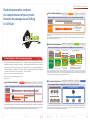
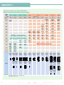
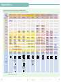
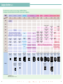
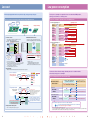
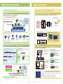
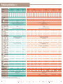
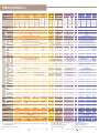
Renesas Microcomputer 8-bit All Flash Renesas Microcomputer 8-bit All Flash 78K0S, 78K0 Microcontrollers Empower your creativity © 2005, 2010. Renesas Electronics Corporation, All rights reserved. Printed in Japan. R01CL0004EJ0200 Colophon 1.0 www.renesas.com 2010.12 All Flash Shifting to "All Flash" 78K0 higher expansion 78K0/Lx3 For power meters 100-pin 78K0/LG3-M LCD controller/driver 80-pin 78K0/LF3 64-pin 78K0/LE3 52-pin 78K0/LD3 48-pin 78K0/LC3 Low-power, wide-voltage operation Wide-voltage operation 40/44/48-pin 78K0/KC2-L 36/48-pin 78K0/KC2-A 80-pin 78K0/KF2 30-pin 78K0/KB2-L 78K0/KE2 20/25/32-pin 78K0/KA2-L 30-pin 78K0/KB2-A 64-pin 16-pin 78K0/KY2-L 52-pin 78K0/KD2 38/44/48-pin 78K0/KC2 30/36-pin 78K0/KB2 µPD78F8025 LED lighting control Answering ever more specific needs, contributing to cost cutting, delivering peace of mind that can be relied on. To ensure that our diversified offering of 8-bit microcontrollers designed for many different applications truly empower our customers, which path should we aim for? Renesas Electronics, which has consistently been tracing the future course of microcontrollers, has come up with an answer, embodied by its shift to All Flash: To offer a full lineup consisting entirely of flash memory products. A truly diversified lineup that offers a full range of products, which are available with 10 to 100 pins and ROM capacity of 1 KB to 128 KB; cuts total cost by allowing program changes, the incorporation of peripheral functions, and lower power consumption; as well as providing a full range of development tools that dramatically enhance ease of use. More than just providing its devices with sophisticated functions, Renesas Electronics has also created an entire infrastructure that ranges from the development of flash microcontrollers to their delivery. 64-pin µPD78F8025 30/32-pin 64-pin µPD78F0714 20-pin 30-pin µPD78F0712 78K0/IB2 78K0/IA2 16-pin 78K0/IY2 30-pin µPD78F0711 USB2.0 function 30-pin µPD78F0730 30-pin µPD179F11x 78K0S/Kx1+ Low pin count microcontrollers 78K0S Microcontrollers Industrial equipment t Power supplies, lighting inverters, LED lighting control 38-pin µPD179F12x Portable audio, component stereo systems i 48-pin 78K0/KC2-C 78K0/Ix2 Inverter motor control For preset remote control Audio b 64-pin 78K0/KE2-C µPD179F1xx Digital still cameras, digital video cameras, SLR cameras Industrial motors, control equipment, vending machines, power meters Supports digital home appliance communication µPD78F0730 Cameras - 78K0/Kx2-C High-resolution A/D converter, wide-voltage operation µPD78F071x 8 78K0 Microcontrollers 64-pin 78K0/LE3-M 78K0/Kx2-L 78K0/Kx2 A new evolution leading to system development success All Flash microcontrollers are suitable for various application fields and raise the commercial value of customer systems. 78K0/Lx3-M 78K0/Kx2-A All of our 8-bit general-purpose microcontrollers employ reliable flash memories. Application examples 78K0R Microcontrollers Portable devices Computer peripherals LBP, PPC, MFP, inkjet printers, scanners, fax machines 0 78K0S/KA1+ 16-pin 78K0S/KY1+ 10-pin 78K0S/KU1+ Air conditioners, refrigerators, washing machines, microwave ovens Preset remote control, etc. Video and recording equipment Other Electronic instruments, electric bidets, toys, etc. Blu-ray players, Blu-ray recorders, industrial cameras 2 78K0S/KB1+ 20-pin Remote control Home appliances PDA, IC recorders 30/32-pin 1 0. 1 2 Merits of flash microcontrollers Flash microcontrollers can boost the competitiveness of your systems. Based on this concept, we are shifting to "All Flash". For hardware designers Software development Hardware development Ordering Production Mass-produced flash microcontrollers require evaluation only once, reducing development man-hours. Use of mask ROM microcontrollers Development and evaluation of flash microcontrollers Use of All Flash microcontrollers Development and evaluation of flash microcontrollers Mass production of flash microcontrollers Development and evaluation of mask ROM microcontrollers Mass production of mask ROM microcontrollers Man-hours required for development reduced by half. Mass production of flash microcontrollers In the case of mass-produced mask ROM microcontrollers, evaluations of both flash microcontrollers and mask ROM microcontrollers are required. Since evaluated flash microcontrollers can be directly mass-produced, the man-hours required for development are reduced by half, resulting in greatly shortened development TAT. For purchasing divisions Software development Ordering Hardware development Production Flash microcontrollers protect you from fluctuations in demand and can reduce dead stock. Predicted demand Overstock Quantity Use of mask ROM microcontrollers Flash microcontrollers offer overwhelming advantages. Overstock or shortage Set A Set A Shortage Set B Compared to mask ROM microcontrollers, flash microcon- In addition, when flash microcontrollers are used for prod- trollers definitely contribute to speeding up system devel- ucts with many different versions or that are localized for opment. Microcontrollers can be ordered before program specific regions, the cost of ordering mask ROM microcon- completion and programs can be written even after the mi- trollers is eliminated and purchase and stock management crocontroller has been mounted on the board. Microcon- costs can be slashed. Use of All Flash microcontrollers Quantity Start of manufacturing Reordering and dead stock Software changes Set B Dead stock Set B' Demand fluctuations Set B' Set A Set B The demand prediction burden is reduced because a blanket order can be placed. Product cycles Software changes No overstock and no shortage Set A Set B Set B Software changes Can be used for other products to compensate for shortages. No dead stock No reordering required No reordering is required even when software is changed, allowing you to start manufacturing immediately without having dead stock. Mass-produced mask ROM microcontrollers may become dead stock as the result of changes in software or fluctuations in demand. On the other hand, flash microcontrollers can be mass-produced immediately after software changes and used for other products, resulting in fewer lost opportunities, less dead stock, and lower ordering costs. troller order placement and program development can therefore be done concurrently, allowing TAT to be shortened as a result. For software designers Software development Hardware development Ordering Production Software can be changed just before mass production starts and development TAT can also be shortened. Use of mask ROM microcontrollers Use of All Flash microcontrollers Mask All Flash Software development Evaluation Ordering Fabrication Software development Evaluation Mass production Evaluation Mass production Shortening of TAT Ordering For manufacturing divisions 8 - b i t Hardware development Production Ordering Parts sharing makes production planning easier and boosts production efficiency. Use of mask ROM microcontrollers Mask Mask Use of All Flash microcontrollers All Flash Mask Assembly (using several types) Set A Since mask ROM microcontrollers cannot be ordered until their specifications are finalized, last-minute software changes can be problematic. On the other hand, specifications for flash microcontrollers can be changed just prior to the start of mass production. Thus orders for flash microcontrollers can be placed while the software is still being developed, allowing the development TAT to be shortened. Software development Set B Assembly (using one type only) Set C Set A Set B Set C In the case of mass-produced mask ROM microcontrollers, the use of different software for different products necessitates the use of a different microcontroller for each type of product. In contrast, mass-produced flash microcontrollers facilitate the sharing of parts since they can be used for various products by simply rewriting the software. 2 0 1 0. 1 2 Wide variety of products for specific applications Unsure about flash microcontrollers? Renesas Electronics can dispel your concerns in flash microcontrollers. We offer ideal products for various applications. Renesas Electronics offers a wide range of products for specific applications, such as the 78K0/Ix2 and µPD78F8025, provided with an inverter control feature for fluorescent and LED lighting, the 78K0/Kx2-C for digital AV applications, the µPD179F1xx, ideal for remote control of home electronics devices, the 78K0/Lx3M for power meters, and µPD78F071x, ideal for controlling motors. In addition to the basic features, the specialized features of the products are well developed, enabling you to choose the best product for your application. High reliability “Reliability” is the concept. Compared to mask ROM microcontrollers, flash microcon- has successfully cleared various hurdles by adapting de- trollers definitely speed up system development. On the velopment, production, sales, and distribution processes other hand, they are often considered as expensive and specifically for flash microcontrollers, to offer reliable mi- available in limited configurations. Renesas Electronics crocontrollers that are attractive in all respects. Large selection We offer enhanced 293 products. To respond to demands for various types of microcontrollers, we offer a range of 293 All Flash 8-bit microcontrollers featuring various pin counts, ROM capacities, packages, etc. Among these, the 78K0/Kx2, 78K0/Kx2-A, µPD78F8025, and µPD78F071x feature an operating speed of 20 MHz; the 78K0/Kx2-L, 78K0/Kx2, 78K0/Kx2-A, µPD78F8025, and 78K0/Lx3 feature a wide power supply range of 1.8 to 5.5 V. The package lineup includes low-pin-count SSOPs (16, 20, and 30 pins), a 32-pin 5 × 5 mm WQFN and a 40-pin 6 × 6 mm WQFN. With these packages, we have achieved a 46% reduction in package thickness and reduction in package size of up to 87% compared with our conventional 8bit microcontrollers (which come in an 80-pin LQFP with a size of 14 mm × 14 mm), helping you reduce the size of your set. Our large selection allows you to select the best product for your needs. Low cost Compared to the 7.6 mA operating current of conventional mask ROM products that run on 5 V/10 MHz (using an external ceramic resonator), the 78K0/Kx2, 78K0/Kx2-L, and 78K0/Kx2-A have a low operating current of 2.3 mA (1.9 mA for the 78K0/Lx3) when running on 10 MHz (using an external ceramic resonator), and just 1.4 mA (1.3 mA for the 78K0/Kx2-L) when running on 8 MHz (using an internal oscillator) under the same operating conditions. Thus lower power consumption than that of conventional mask ROM products can be achieved with our flash microcontrollers. RAM 96 K LEDs Refrigerators Washing machines µPD78F071x (bytes) 7K 7K 5K 5K Incorporated software protection functions Our products incorporate our experience and technology in the automotive field as well as software protection functions. All our products incorporate the experience we have gained in the process of supplying microcontrollers for over 1,000 types of applications and the technology we developed for flash microcontrollers for the automotive field. Our products also feature functions that disable reading and malicious software rewriting and erasing, thus offering maximum protection of your valuable software. PG-FP5 Flash memory programmer Writing Writing You can disable writing. Erasing Erasing You can disable erasing. 5K 3K 3K 3K 3K 2K 3K 2K 2K 48 K 2K 2K 2K 2K 2K 2K 2K 2K 2K 1K 1K 24 K 1K 768 768 16 K 4K 128 128 384 384 256 384 2K 128 128 1K 1K 1K 1K 1K 1K 1K 1K 1K 1K 1K 1K 1K 1K 1K 1K 1K 1K 1K 1K 768 1 K 768 768 768 768 768 1 K 768 768 512 512 256 512 512 256 512 8K 1K 1K 1K 1K 768 768 768 768 768 512 512 768 512 512 1K 512 768 768 78K0S/Kx1+ 78K0/Ix2 78K0/Kx2 78K0/Kx2-L 78K0/Kx2-A 256 768 128 128 78K0/Kx2-C µPD78F8025 µPD78F071x 78K0/Lx3 78K0/Lx3-M xUn xYn xAn xBn xCn xDn xEn xFn 10 16 20/25/32 30/32/36 36/38/40/44/48 52 64 80 Rich development environment We offer inexpensive, easy-to-use, and convenient tools. 512 128 No commands for reading are provided. Reading 7K 3K 32 K Blenders Reading 60 K xGn Commercial name 100 Pin count CubeSuite automatically generates source code (a device driver program) to control the microcontroller peripherals (such as the timers, UART, and A/D conver- Top screen Code generated easily Renesas Electronics provides an easy-to-use and convenient development environment, exemplified by our newly released CubeSuiteTM integrated development platform. CubeSuite can be used to compile and debug programs, manage pin layouts, generate code for microcontroller peripherals, and execute high-speed building. Add MINICUBE2, an on-chip debug emulator with flash memory programming capability, into the mix and you have a powerful environment that enables fast and accurate system development. Total cost reduction through embedded peripheral IC functions Flash memory Reset function Rice grain size despite rich content We have drastically reduced costs through the application of new processes, etc., overturning the conventional notion that flash microcontrollers are expensive. Our microcontrollers use flash memory instead of EEPROMTM, an internal oscillator, a voltage detection function (LVI), a reset function, and various other functions normally provided externally, which translates into considerably lower total system cost for you. About 1/3 that of mask ROM products. Fluorescent lights Entire lineup consisting of flash memory products Memory 128 K Our low prices overturn conventional notions. Low power consumption 78K0/Ix2, µPD78F8025 Internal oscillator Voltage detection function 64-pin chip size image V DD The configuration on the right enables the operation thanks to the internal oscillator. (LVI, ADC) GND RESET Support for mass production Programming environment supporting All Flash products Flash memory programmers made by Renesas Electronics In addition to a large lineup of programming tools, we also offer programming services. Renesas Electronics and partner manufacturers offer a large number of programming tools, making programming possible in many different settings such as development environments and production lines. Moreover, programming services are also available from partner manufacturers both in Japan and overseas, serving a broad range of needs such as large-volume programming after shipping. PG-FP5 MINICUBE2 Flash memory programmers made by partner manufacturers Naito Densei Machida Mfg. Co., Ltd. Yokogawa Digital Computer Corporation FL-PR5 NET IMPRESS Series Wave Technology Co., Ltd. We offer programmed products. The programmed products are shipped similarly to mask ROM products. Realization of lower power consumption than mask ROM products External ceramic resonator 10 MHz Flash memory 78K0/Kx2, 78K0/Kx2-L, 78K0/Kx2-A 8 External ceramic resonator 10 MHz 78K0/Lx3 External ceramic resonator 10 MHz 78K0/Kx2 78K0/Kx2-A, 78K0/Lx3 Internal oscillator 8 MHz 78K0/Kx2-L Internal oscillator 8 MHz - b i microcontroller Operating current Condition (5 V power supply voltage) Mask ROM products Flash Shorter delivery time than that of mask ROM products, even if they are programmed products. Coding ordered 7.6 mA Waiting period for the delivery of the products Stick GANG Writer Delivery 1.9 mA 1.4 mA t Y3000-8 Interface Co., Ltd. Several weeks Mask ROM products 2.3 mA 1.3 mA TESSERA Technology Inc. Comparison with Renesas Electronics products All Flash microcontrollers Programming houses Delivery time reduced by half or more Caution Delivery time may vary depending on purchase conditions such as order quantity. 2 0 1 0. 1 2 StickWriter ITF2000 Large selection (1/3) We offer flash microcontrollers in various packages and ROM or RAM sizes, allowing you to select the best flash microcontroller for your product or application. Commercial Name Pin Count ROM (bytes) 128 K 78K0S/KU1+ 78K0S/KY1+ 78K0S/KA1+ 78K0S/KB1+ 78K0/KB2 10-pin 16-pin 20-pin 30/32-pin 30/36-pin 78K0/KC2 38-pin 44-pin 78K0/KD2 78K0/KE2 78K0/KF2 52-pin 64-pin 80-pin µPD78F0527A, µPD78F0527DA*2 (7 K) µPD78F0537A, µPD78F0537DA*2 (7 K) µPD78F0547A, µPD78F0547DA*2 (7 K) µPD78F0526A (5 K) µPD78F0536A (5 K) µPD78F0546A (5 K) 48-pin Product name (RAM (bytes)) 96 K 60 K µPD78F0515A, µPD78F0515DA*2 (3 K) µPD78F0525A (3 K) µPD78F0535A (3 K) µPD78F0545A (3 K) 48 K µPD78F0514A (2 K) µPD78F0524A (2 K) µPD78F0534A (2 K) µPD78F0544A (2 K) 32 K 24 K 16 K 78K0S/Kx1+ Microcontrollers (Low Pin Count Microcontrollers) 8K µPD78F9224 (256) µPD78F9234 (256) µPD78F9232 (256) µPD78F0503A, µPD78F0503DA*2 (1 K) µPD78F0513A, µPD78F0513DA*2 (1 K) µPD78F0513A, µPD78F0513DA*2 (1 K) µPD78F0513A (1 K) µPD78F0523A (1 K) µPD78F0533A (1 K) µPD78F0502A (1 K) µPD78F0512A (1 K) µPD78F0512A (1 K) µPD78F0512A (1 K) µPD78F0522A (1 K) µPD78F0532A (1 K) µPD78F0501A (768) µPD78F0511A (768) µPD78F0511A (768) µPD78F0511A (768) µPD78F0521A (768) µPD78F0531A (768) µPD78F0500A (512) 4K µPD78F9202, µPD78F9502 (128) µPD78F9212, µPD78F9512 (128) µPD78F9222 (256) 2K µPD78F9201, µPD78F9501 (128) µPD78F9211, µPD78F9511 (128) µPD78F9221 (128) 1K µPD78F9200, µPD78F9500 (128) µPD78F9210, µPD78F9510 (128) 10-pin SSOP (MA) Thickness: 1.2 mm 5.72 mm (225) Pitch: 0.65 mm 16-pin SDIP*1 (CS) 16-pin SSOP*1 (MA) Thickness: 2.8 mm Thickness: 1.5 mm 5.72 mm (225) 7.62 mm (300) Pitch: 0.65 mm Pitch: 1.778 mm 20-pin SDIP (CS) Thickness: 2.8 mm 7.62 mm (300) Pitch: 1.778 mm 32-pin SDIP (CS) Thickness: 2.8 mm 7.62 mm (300) Pitch: 1.778 mm 30-pin SSOP (MC) Thickness: 1.2 mm 7.62 mm (300) Pitch: 0.65 mm 16-pin SSOP (GR) 16-pin WLBGA*1 (FH) Thickness: 1.44 mm Thickness: 0.4 mm 5.72 mm (225) 2 × 2.3 mm Pitch: 0.65 mm Pitch: 0.5 mm 20-pin SSOP (MC) Thickness: 1.2 mm 7.62 mm (300) Pitch: 0.65 mm 30-pin SSOP (MC) Thickness: 1.2 mm 7.62 mm (300) Pitch: 0.65 mm 36-pin FLGA (FC) Thickness: 0.91 mm 4 × 4 mm Pitch: 0.5 mm Package 78K0/Kx2 Microcontrollers 38-pin SSOP (MC) Thickness: 1.7 mm 7.62 mm (300) Pitch: 0.65 mm 44-pin LQFP (GB) Thickness: 1.4 mm 10 × 10 mm Pitch: 0.8 mm 48-pin LQFP (GA) Thickness: 1.4 mm 7 × 7 mm Pitch: 0.5 mm 52-pin LQFP (GB) Thickness: 1.4 mm 10 × 10 mm Pitch: 0.65 mm 64-pin LQFP (GC) Thickness: 1.4 mm 14 × 14 mm Pitch: 0.8 mm 64-pin LQFP (GK) Thickness: 1.4 mm 12 × 12 mm Pitch: 0.65 mm 64-pin LQFP (GB) Thickness: 1.4 mm 10 × 10 mm Pitch: 0.5 mm 64-pin TQFP (GA) Thickness: 1.0 mm 7 × 7 mm Pitch: 0.4 mm 64-pin FLGA (FC) Thickness: 0.91 mm 5 × 5 mm Pitch: 0.5 mm 64-pin FPBGA (F1) Thickness: 0.69 mm 4 × 4 mm Pitch: 0.4 mm *1 µPD78F9210, 78F9211, and 78F9212 only *2 Supports on-chip debugging of 78K0/Kx2 Remark The packages are shown in their actual size. 8 - b i t 2 0 1 0. 1 2 80-pin LQFP (GC) Thickness: 1.4 mm 14 × 14 mm Pitch: 0.65 mm 80-pin LQFP (GK) Thickness: 1.4 mm 12 × 12 mm Pitch: 0.5 mm Large selection (2/3) We offer flash microcontrollers in various packages and ROM or RAM sizes, allowing you to select the best flash microcontroller for your product or application. Commercial Name 78K0/KY2-L 78K0/KA2-L 78K0/KB2-L 78K0/KC2-L 78K0/KB2-A 78K0/KC2-A 78K0/KC2-C* 78K0/KE2-C* 16-pin 20/25/32-pin 30-pin 40/44/48-pin 30-pin 36/48-pin 48-pin 64-pin 60 K µPD78F0762 (3 K) µPD78F0765 (3 K) 48 K µPD78F0761 (2 K) µPD78F0764 (2 K) µPD78F0760 (1 K) µPD78F0763 (1 K) Pin Count ROM (bytes) 128 K µPD179F1xx 30-pin 38-pin µPD179F114 (1 K) µPD179F124 (1 K) µPD179F113 (1 K) µPD179F123 (1 K) µPD78F0730 30-pin Product name (RAM (bytes)) 96 K µPD78F0583, µPD78F0588 (1 K) µPD78F0573, µPD78F0578 (1 K) 32 K µPD78F0591 (1 K) µPD78F0593 (1 K) 24 K 16 K µPD78F0552, µPD78F0557 (768) µPD78F0562, µPD78F0567 (768) µPD78F0572, µPD78F0577 (768) µPD78F0582, µPD78F0587 (768) 8K µPD78F0551, µPD78F0556 (512) µPD78F0561, µPD78F0566 (512) µPD78F0571, µPD78F0576 (512) µPD78F0581, µPD78F0586 (512) 4K µPD78F0550, µPD78F0555 (384) µPD78F0560, µPD78F0565 (384) 1K 16-pin SSOP (MA) Thickness: 1.5 mm 5.72 mm (225) Pitch: 0.65 mm Package µPD78F0592 (1 K) µPD179F112 (768) µPD179F122 (768) µPD78F0730 (3 K) 38-pin SSOP (MC) Thickness: 1.7 mm 7.62 mm (300) Pitch: 0.65 mm 30-pin SSOP (MC) Thickness: 1.2 mm 7.62 mm (300) Pitch: 0.65 mm µPD179F111 (512) µPD179F110 (512) 78K0/Kx2-L Microcontrollers 2K 78K0/Kx2-C Microcontrollers 12-bit A/D Converter for Digital AV Applications 78K0/ Kx2-A USB Micro controllers Microcontrollers for MicroPreset Remote Control controllers µPD78F0590 (1 K) 20-pin SSOP (MC) Thickness: 1.2 mm 7.62 mm (300) Pitch: 0.65 mm 30-pin SSOP (MC) Thickness: 1.2 mm 7.62 mm (300) Pitch: 0.65 mm 44-pin LQFP (GB) Thickness: 1.4 mm 10 × 10 mm Pitch: 0.8 mm 32-pin WQFN (K8) Thickness: 0.75 mm 5 × 5 mm Pitch: 0.5 mm 48-pin LQFP (GA) Thickness: 1.4 mm 7 × 7 mm Pitch: 0.5 mm 25-pin FLGA* (FC) Thickness: 0.69 mm 3 × 3 mm Pitch: 0.5 mm 40-pin WQFN (K8) Thickness: 0.75 mm 6 × 6 mm Pitch: 0.5 mm 30-pin SSOP (MC) Thickness: 1.2 mm 7.62 mm (300) Pitch: 0.65 mm 48-pin LQFP (GA) Thickness: 1.4 mm 7 × 7 mm Pitch: 0.5 mm 48-pin LQFP (GA) Thickness: 1.4 mm 7 × 7 mm Pitch: 0.5 mm 64-pin LQFP (GB) Thickness: 1.4 mm 10 × 10 mm Pitch: 0.5 mm 30-pin SSOP (MC) Thickness: 1.2 mm 7.62 mm (300) Pitch: 0.65 mm 36-pin FLGA* (FC) Thickness: 0.69 mm 4 × 4 mm Pitch: 0.5 mm * Under development Remark The packages are shown in their actual size. 8 - b i t 2 0 1 0. 1 2 Large selection (3/3) We offer flash microcontrollers in various packages and ROM or RAM sizes, allowing you to select the best flash microcontroller for your product or application. Commercial Name 78K0/IY2 78K0/IA2 78K0/IB2 µPD78F8025 Pin Count ROM (bytes) 16-pin 20-pin 30/32-pin 64-pin 128 K Product name (RAM (bytes)) µPD 78F071x 78K0/LE3-M*1 78K0/LG3-M*1 78K0/LC3 78K0/LD3 78K0/LE3 78K0/LF3 48-pin 52-pin 64-pin 80-pin 60 K µPD78F0445, µPD78F0455, µPD78F0465 (2 K) µPD78F0485, µPD78F0495, µPD78F0475 (2 K) µPD78F8055 (2 K) 48 K µPD78F0444, µPD78F0454, µPD78F0464 (2 K) µPD78F0484, µPD78F0494, µPD78F0474 (2 K) µPD78F8054 (2 K) 30-pin 64-pin 64-pin 100-pin 96 K 32 K 24 K 78K0/Ix2 Microcontrollers for Power Supplies, Lighting Inverters, and LED Lighting Control µPD78F8025 (1 K) µPD78F0714 (1 K) µPD78F0403, µPD78F0413 (1 K) µPD78F0402, µPD78F0412 (1 K) µPD78F0423, µPD78F0433 (1 K) µPD78F0422, µPD78F0432 (1 K) µPD78F0443, µPD78F0453, µPD78F0463 (1 K) µPD78F0483, µPD78F0493, µPD78F0473 (1 K) µPD78F0442, µPD78F0452, µPD78F0462 (1 K) µPD78F0482, µPD78F0492, µPD78F0472 (1 K) µPD78F0441, µPD78F0451, µPD78F0461 (768) µPD78F0481, µPD78F0491, µPD78F0471 (768) 16 K µPD78F0742, µPD78F0752 (768) µPD78F0744, µPD78F0754 (768) µPD78F0746, µPD78F0756 (768) µPD78F8024 (512) µPD78F0712 (768) µPD78F0401, µPD78F0411 (768) µPD78F0421, µPD78F0431 (768) 8K µPD78F0741, µPD78F0751 (512) µPD78F0743, µPD78F0753 (512) µPD78F0745, µPD78F0755 (512) Microcontrollers µPD78F0711 (768) µPD78F0400, µPD78F0410 (512) µPD78F0420, µPD78F0430 (512) 4K µPD78F0740, µPD78F0750 (384) for LED Lighting Control 2K Microcon trollers for Inverter Mo tor Control µPD78F8053 (1 K) µPD78F8052 (768) 78K0/Lx3-M Microcontrollers for Power Meters 78K0/Lx3 Microcontrollers 1K 16-pin SSOP (MA) Thickness: 1.5 mm 5.72 mm (225) Pitch: 0.65 mm Package 20-pin SOP (MC) Thickness: 1.7 mm 7.62 mm (300) Pitch: 1.27 mm 30-pin SSOP (MC) Thickness: 1.2 mm 7.62 mm (300) Pitch: 0.65 mm 20-pin SSOP (MC) Thickness: 1.2 mm 7.62 mm (300) Pitch: 0.65 mm 32-pin WQFN (K8) Thickness: 0.75 mm 5 × 5 mm Pitch: 0.5 mm 64-pin LQFP (GK) Thickness: 1.4 mm 12 × 12 mm Pitch: 0.65 mm 30-pin SSOP (MC) Thickness: 1.2 mm 7.62 mm (300) Pitch: 0.65 mm 64-pin TQFP (GK) Thickness: 1.0 mm 12 × 12 mm Pitch: 0.65 mm 48-pin LQFP (GA) 52-pin LQFP (GB) Thickness: 1.4 mm Thickness: 1.4 mm 7 × 7 mm 10 × 10 mm Pitch: 0.5 mm Pitch: 0.65 mm 64-pin LQFP (GK) 64-pin LQFP (GB) Thickness: 1.4 mm Thickness: 1.4 mm 12 × 12 mm 10 × 10 mm Pitch: 0.65 mm Pitch: 0.5 mm 80-pin LQFP (GC) Thickness: 1.4 mm 14 × 14 mm Pitch: 0.65 mm 64-pin TQFP*2 (GA) Thickness: 1.0 mm 7 × 7 mm Pitch: 0.4 mm 80-pin LQFP (GK) Thickness: 1.4 mm 12 × 12 mm Pitch: 0.5 mm *1. Under development *2. µPD78F044x and 78F045x only Remark The packages are shown in their actual size. 8 - b i t 2 0 1 0. 1 2 64-pin LQFP (GB) 100-pin LQFP (GC) Thickness: 1.4 mm Thickness: 1.4 mm 10 × 10 mm 14 × 14 mm Pitch: 0.5 mm Pitch: 0.5 mm Low cost Low power consumption The low power consumption is comparable to that of conventional mask ROM products, allowing you to build more eco-friendly systems. All the required peripheral functions are provided on chip, saving you money and space. Total cost reduction achieved through the following on-chip peripheral functions Low power consumption comparable to that of mask ROM products EEPROM Board downsizing Package downsizing 78K0/Kx2 78K0/Lx3 78K0S/Kx1+ Conventional mask ROM microcontrollers Internal oscillator EEPROM emulation function*4 Various oscillators are embedded. The flash microcontroller can operate with just an internal oscillator. Any block can be used as nonvolatile memory for storing data with the self-programming function of the flash memory. External clock Low-speed internal oscillator or CPU MPX X1 clock External resonator High-speed internal oscillator The external resonator pin can be used as an I/O if no external resonator is needed. MPX Sub-clocks *2 Peripheral functions*3 VDD Data 2 Data 1 Data 1 Minimum erasure unit GND Data length (number of bytes) RESET *1 78K0S/Kx1+ and µPD78F071x only *2 Sub-clocks are not provided for the 78K0S/Kx1+, 78K0/KB2, 78K0/KY2-L, 78K0/KA2-L, 78K0/KB2-L, 78K0/KB2-A, 78K0/Ix2, µPD78F0730, µPD179F1xx, and µPD78F8025. *3 Use an external resonator or an external input clock when using the USB function incorporated in the µPD78F0730. *4 Except µPD78F071x, µPD78F0730, and µPD179F1xx Operation mode Resonator 10 MHz 78K0/Kx2, 78K0/Kx2-L, 78K0/Kx2-A Resonator 10 MHz 78K0/Lx3 Resonator 10 MHz 78K0/Kx2, 78K0/Kx2-A, 78K0/Lx3 78K0/Kx2-L Conventional mask ROM microcontrollers Maximum number of data items stored in one block (Outline) The configuration below enables the operation. Conventional mask ROM microcontrollers 7.6 mA 2.3 mA 70% reduced 1.9 mA 75% reduced Internal oscillator 8 MHz 1.4 mA 82% reduced Internal oscillator 8 MHz 1.3 mA 83% reduced Power supply voltage: 3 V Writing of next data item (Data 2) Minimum erasure units 78K0/Kx2, 78K0/Kx2-L, 78K0/Kx2-A, 78K0/Kx2-C, 78K0/Lx3, 78K0/Lx3-M, 78K0/Ix2, µPD78F8025: 1 KB 78K0S/Kx1+: 256 bytes Watchdog timer *1 Operating current Power supply voltage: 5 V Reset & WDT IC Resonator × Number of erasures in one block*5 *5 78K0S/Kx1+: 1,000 times, 78K0/Kx2, 78K0/Kx2-L, 78K0/Kx2-A, 78K0/Kx2-C, 78K0/Lx3, 78K0/Lx3-M, 78K0/Ix2, µPD78F8025: 10,000 times (4 KB) Remark See the user’s manual (EEPROM emulation library) for details. HALT mode Standby current Resonator 32.768 kHz 6 µA 78K0/Kx2 Resonator 32.768 kHz 3.5 µA 42% reduced 78K0/Lx3 Resonator 32.768 kHz 2.4 µA 60% reduced 78K0/Kx2-L Resonator 32.768 kHz 78K0/Kx2, 78K0/Kx2-A, 78K0/Kx2-C, 78K0/Lx3, µPD179F1xx STOP mode 78K0/Kx2-L 1 µA 73% reduced All clocks stop. 1 µA All clocks stop. 0.3 µA Remark The current values are typical values. Reset function Highly accurate and user-friendly voltage detection and reset functions are incorporated. 1.59 V ±0.15 V (fixed) Power-on clear function Reduces external resets and voltage detection ICs. Power supply voltage (VDD) Release of reset Occurrence of reset 78K0/Kx2 78K0/Kx2-A 78K0/Kx2-C 78K0/Lx3-M µPD78F0730 µPD78F8025 1.61 V ±0.09 V (fixed) 78K0/Kx2-L Voltage detected 78K0/Lx3 78K0/Ix2 The internal oscillator allows fast startup, eliminating the need for oscillation wait time and reducing average power consumption. Power-consumption reduction achieved by fast startup 1.80 V ±0.1 V (fixed) µPD179F1xx 2.1 V ±0.1 V (fixed) 78K0S/Kx1+ 3.5 V ±0.2 V (fixed) µPD78F071x Voltage detection function Interrupt or reset Interrupt or reset can be selected by software. Interrupt or reset Power supply voltage (VDD) Selectable with software 12 V The 78K0/Kx2, 78K0/Kx2-L, 78K0/Kx2-A, 78K0/Kx2-C, 78K0/Lx3, 78K0/Lx3-M, and µPD78F8025 also have the functions on the right. Regulator IC 5V VDD pin 78K0/Kx2 78K0/Kx2-L 78K0/Kx2-A 1.3 V 78K0/Kx2-C 78K0/Lx3 EXLVI pin (alternately used 78K0/Lx3-M µPD78F8025 as a port) Includes a pin (EXLVI) for inputting a reference voltage, allowing the detection of power supply voltages including power supply voltage for the microcontroller (VDD) Microcontroller operation starts with clock from external resonator. Wait time for oscillation stabilization is required at the beginning of the oscillation. At power on Accuracy of ±0.1 V* * 78K0/Kx2, 78K0/Kx2-A, 78K0/Kx2-C, 78K0/Lx3, 78K0/Lx3-M, 78K0/Ix2, µPD78F0730, µPD179F1xx, µPD78F8025,: When any voltage is set 78K0/Kx2-L: When a voltage other than 2.07 V is set 78K0S/Kx1+: When a voltage of 2.6 V or less is set µPD78F071x: Accuracy of ±0.2 V Voltage detected Wait time + oscillation stabilization time: Several ms to several dozen ms Microcontrollers without internal oscillator Wait 78K0, 78K0S All Flash 70.83 µs (TYP.)*1 Microcontroller operation starts with internal oscillation clock. When standby is released 78K0, 78K0S All Flash Wait STOP mode 2.4 µs (TYP.)*2, 3 Microcontroller operation starts with internal oscillation clock. Internal oscillators require almost no wait time for oscillation stabilization. The non-productive time intervals indicated by the arrows above are eliminated, which reduces the average power consumption. Highly reliable watchdog timer Refer to the watchdog timer description on page 21. *1 In the case of the µPD78F071x. 78K0S/Kx1+: 544 µs (TYP.) *2 In the case of the 78K0/Kx2, 78K0/Kx2-L, 78K0/Kx2-A, 78K0/Kx2-C, µPD78F8025, 78K0/Lx3, and 78K0/Ix2. µPD179F1xx: 4.8 µs, µPD78F0730: 5 µs, µPD78F071x: 70.83 µs *3 78K0/Kx2, 78K0/Kx2-A, 78K0/Kx2-C, µPD78F8025: When oscillation frequency is 10 MHz or less (AMPH = 0) 8 - b i t 2 0 1 0. 1 2 Wide variety of products for specific applications (1/2) We offer ideal products for various applications. You can choose the optimal product for your needs. Microcontrollers for power supplies, lighting inverters, and LED lighting control (78K0/Ix2), microcontrollers for LED lighting control (µPD78F8025) (1/2) Renesas Electronics has developed a dedicated driver capable of independently driving lighting control, which can be used to facilitate system configuration. By using the 78K0/Ix2, you can achieve low power consumption through PFC/dimmer control and by linking operations with a network. The µPD78F8025 allows efficient and reliable control thanks to its switching-type constant current driver and extensive on-chip protection circuits, including circuits to prevent overcurrent and overheating. Lighting ballast control PFC control DC350 V Half-bridge circuit Microcontrollers for power supplies, lighting inverters, and LED lighting control (78K0/Ix2), microcontrollers for LED lighting control (µPD78F8025) (2/2) A wide range of tools to aid the efficient development of high-performance lighting [Lighting solution evaluation boards] • Renesas Electronics provides evaluation boards dedicated to each lighting application. Everything you need to evaluate your system, including manuals, circuit diagrams, and development tools, can be downloaded from our website, providing you with fine-tuned, comprehensive development support. Lighting Applications DC350 V AC power supply Illumination Lighting LED Solution Microcontroller only General Lighting Fluorescent Lighting Solution Lighting Communication Master Evaluation Board Ballast (inverter) fluorescent light EZ-BLST-003 Lighting communication master evaluation board EZ-0008 Microcontroller + driver Lamp protection 16-bit timer X0 A/D converter & comparator Dimmer input DALI (UART) DALI/RF Evaluation board 78K0/IB2 HBLED evaluation board EZ-0005 16-bit timer X1 I2C 3-wire serial communication Remote control 8-bit CPU 16-bit timer 00 8-bit MCU 78K0/Ix2 LED lighting 78K0/IA2 PWM evaluation board EZ-0006 Mounted device (MCU) DC9 V to 38 V µPD168804 step-down HBLED evaluation board EZ-0007 (78K0/Ix2) Channel 0 Reg. • Solution boards can be evaluated separately. When evaluating lights that feature communication capabilities, each solution board can be evaluated separately in combination with a master evaluation board. 5V 5V Dimming PWM Dimmer input EN 78K0 / Ix2 78K0/Ix2 DALI DMX512 I2 C NNCD or ZDi 4ch High-current 4-channel LED Driver high-current PWM0-3 Channel 1 [Automatic software generator] Applilet® EZ for HCD Channel 2 LED driver 16-bit/610 Hz Remote control µPA2756, etc. uPD168804 µPD168804 SH Channel 3 Applilet EZ for HCD automatically generates sample software for LED lighting, which can then be written to the microcontroller on the board. Applilet EZ for HCD is easy to operate even for first-time users, and will lighten your software development load. LCD control in digital TVs LVDS Digital TV Broadcast Backlight signal reception block Frame rate control Timing control 8-bit microcontroller µPD78F8024 µPD78F8025 LCD driver Source/gate driver LCD panel PWM signals (4) LED driver LED driver µPD168804 Reg. µPD168804 Reg. Reg. Edge-type LED backlight 8 - b i t 2 0 1 0. 1 2 Wide variety of products for specific applications (2/2) Microcontrollers for digital AV applications (78K0/Kx2-C) Microcontrollers for power meters (78K0/Lx3-M) 1. Reduction in standby power All the features required to realize a single-phase power meter integrated on a single LSI. The operating current when transmitting and receiving via HDMITM-CEC has been reduced by 99.8%. About 5 mA Operating current corresponding to remote control reception Renesas Electronics makes all the features required to realize a single-phase power meter available on a single LSI, helping you reduce the size of your system. Extensive peripherals also mean that the 78K0/Lx3-M can be used for a variety of power meter applications. CEC and remote control operations performed using subclock. Significant current reduction compared to software. Operating current corresponding to CEC transmission/ reception [Features] 24-bit ∆∑A/D converter (4 channels): 2 channels for current and 2 channels for voltage* High-resolution analog-to-digital conversion On-chip phase regulator regulates input signal phase shift caused by external circuits or components Reduced by 99.8% Precision power metrology Standby current About 10 µA 78K0/Kx2-C General-purpose microcontroller + Software CEC Detection of active power, reactive power, apparent power, RMS voltage, and RMS current Active power calculation error: 0.1% (typ.) Reactive power calculation error: 0.5% (typ.) Current integration A current integrator can be specified to be used or not used for each current channel, and different sensors can be connected. Power quality measurement 2. Reduction in development man-hours Dedicated software that allows CEC line monitoring (CEC Viewer) is available, in addition to conventional development environment. CEC monitoring software HDMI-CEC evaluation board Anti-tamper (fault detection) feature Peak detection Zero-cross detection SAG detection Period and frequency measurement On-chip LCD controller Can be switched between external and internal resistive division Remote-control transmitter Remote-control transmission is achieved by using an 8-bit timer (TMH1) and UART. USB connection On-chip debugger Real-time counter The power supplies are separated, allowing the microcontroller to run on the real-time clock even when the power supply is stopped. USB connection Block diagram of power measurement feature Digital frequency conversion block Integrator block I1 ΛΣ ADC 3. Example applications I2 Power calculation block Fault detection (2-wire only) Integrator Active power calculation Digital frequency conversion CF pin V1 Reactive power calculation V2 Apparent power/ ampere-hour calculation Zero-cross/ timeout detection Digital TVs AV centers DVD (Blu-ray) recorders Interrupt controller Peak detection SAG detection Remark HDMI (High-Definition Multimedia Interface): Standardized digital audio/video I/O interface for home electronics and AV devices. CEC (Consumer Electronics Control): Control protocol (control method) for device control signals standardized by HDMI. By using CEC, multiple AV devices can be controlled by using one remote controller. Power quality management block Period and frequency measurement * 2 channels for current and 1 channel for voltage (3 channels in total) in the µPD78F8052 and 78F8053. 8 - b i t 2 0 1 0. 1 2 CPU High reliability The enhanced watchdog timer (WDT) offers improved reliability and functionality equivalent to that of an external WDT. Conventional microcontrollers 78K0/Kx2, 78K0/Lx3, 78K0S/Kx1+, etc. X1 clock stops WDT function WDT independent from CPU Record of shipment & applications employing our flash microcontrollers The watchdog timer also stops and the microcontroller haywire cannot be detected. The watchdog timer does not stop. Microcontroller haywire The reliability technologies developed for automotive flash microcontrollers can be found in all our flash microcontrollers, making them a safe choice. It is doubtful whether the haywire is detected because counts are cleared by 1-bit flags. No need to worry about haywire because counts are cleared by the byte instruction. Cumulative shipment total: More than 2,000,000,000 unitsNote. Internal oscillation clock 240 kHz (TYP.) Used for more than 1,000 types of applications Main clock Note As of May, 2010 A flash security setting function is provided to protect your software from malicious rewriting and reading. Software protection function PG-FP5 Flash memory programmer Writing Writing Erasing Erasing WDT Independent from CPU CPU peripheral functions This configuration is the same as that in which an external watchdog timer is connected. The WDT does not stop even if the main clock stops. You can disable writing. The 78K0/Kx2, 78K0/Kx2-L, 78K0/Kx2-A, 78K0/Kx2-C, 78K0/Lx3, 78K0/Lx3-M, 78K0/Ix2, µPD179F1xx, and µPD78F8025 have more reliable functions. You can disable erasing. No commands for reading are provided. Reading Reading Window WDT Outline of Window WDT The Window WDT can detect infinite loops. Four types of Window settings can be selected according to the system. Clearance of WDT Quarter of Window opens. WDT WDT Haywire The 78K0/Kx2, 78K0/Kx2-L, 78K0/Kx2-A, 78K0/Kx2-C, 78K0/Lx3, 78K0/Lx3-M, 78K0/Ix2, and µPD78F8025 include a boot swap feature to protect important programs even when power shuts down during self-programming. Problems during self-rewriting Momentary power shutdown Self-rewriting in progress ????? Operation is disabled. Writing to boot 1 Erasing boot 0 Boot swap New Boot Program New Boot Program New Boot Program Boot Boot Program Boot Boot Program WDT Three quarters of Window opens. Count overflow RESET During the closure, clearance is rejected. Boot Boot Program starts xxxxH ROM address 78K0S/Kx1+ WDT Setting 1 Low-speed internal oscillator oscillation Stoppable/unstoppable by software Setting 2 Watchdog timer overflow time*1 3.88 ms (TYP.) to 496.48 ms (TYP.) Setting 3 Setting 1 Low-speed internal oscillator oscillation Stoppable/unstoppable by software Setting 2 Setting of system clock High-speed internal oscillator/external resonator/external CLK Setting 3 Port setting of RESET pin RESET/port Setting 4 Setting of wait time for oscillation stabilization 210/fx to 217/fx 2 Watchdog timer window open time* i t 2 25%/50%/75%/100% µPD78F071x Setting 1 Low-speed internal oscillator oscillation *1 This is 3.88 ms (TYP.) to 3.97 s (TYP.) for the 78K0/Kx2-L and 78K0/Ix2. *2 This can be set to only 100% in the µPD78F0730. b WDT 78K0/Kx2, 78K0/Kx2-L, 78K0/Kx2-A, 78K0/Kx2-C, 78K0/Lx3, 78K0/Lx3-M, 78K0/Ix2, µPD78F0730, µPD179F1xx, µPD78F8025 0080H The microcontroller can start normally even when momentary power shutdown occurs during boot rewriting. - WDT WDT Window fully opens (default). Time during which the counter can be cleared When RESET is released, you can set the setting value with the hardware. Boot Program 0000H 8 WDT Option byte function 0000H Momentary power shutdown Boot Program RESET An option byte function is incorporated to enable important system operation settings by hardware, eliminating setting errors caused by inadvertent program loops. xxxxH Boot 0 Opens WDT Power shutdown during self-rewriting may disable microcontroller recovery. Boot swap function Boot 1 Closes Instruction for clearing the count Half of Window opens. WDTE WDTE WDT starts counting 0 1 0. 1 2 Stoppable/unstoppable by software Rich development environment (1/2) We provide inexpensive, easy-to-use, and convenient development environments, allowing you to select the best development environment according to the device and development conditions. Lineup of development environments Microcontroller training kit Example of inexpensive development environment 78K0S/Kx1+ 78K0/Kx2 78K0/Kx2-L 78K0/Ix2 78K0/Lx3 78K0/Kx2-C Starter kit for Board supplied with Applilet EZ for simple software creation quick microcontroller programming Test boards Pitch conversion board Test boards for MINICUBE2 QB-78K0SKB1-TB QB-78K0KF2-TB QB-78K0KC2L-TB QB-78K0IB2-TB QB-78K0LF3-TB QB-78K0KE2C-TB*4 For 78K0S/KB1+ For 20-pin For 20-pin DIP SSOP package package DIP conversion board Test board*4 78K0S Applilet EZ Development flow Connected to universal board for easy evaluation. EZ-0001 ReferSTAR 78K*1 EZ-0002 Microcontroller training kit For 78K0/KF2 CT-207*1 FB-78F9222MC*2 QB-78K0SKB1-TB For 78K0/KF2 For 78K0/KC2-L For 78K0/KC2-L On-chip debug emulator with flash programming function 78K0 MINICUBE2 (ReferSTAR 78K upgrade kit*1) TK-78K0/KF2*3 TK-78K0/KC2L*3 QB-78K0KF2-TB QB-78K0KC2L-TB QB-78K0IB2-TB QB-78K0LF3-TB For 78K0/IB2 For 78K0/LF3 For 78K0/KE2-C TK-78K0/KE2C*3 For 78K0/KE2-C QB-78K0KE2C-TB*5 Software development Software package (SP78K0S) Debugging/verification Simulator (SM+ for 78K0S/Kx1+) Programming Full-function in-circuit emulator (IECUBE®) Flash memory programmer Assembler (RA78K0S) (PM+ is included.) Compiler (CC78K0S) 78K0S On-chip debug emulator with programming function (MINICUBE2) FL-PR5*2 MINICUBE2 wireless option (QB-MINI2-RF) Full-function in-circuit emulator (IECUBE) Microcontroller integrated development environment (CubeSuite) On-chip debug emulator with programming function (MINICUBE2) Software package (SP78K0) 78K0 1 Assembler (RA78K0) (PM+ is included.) Compiler (CC78K0) MINICUBE2 wireless option (QB-MINI2-RF) Simulator (SM+ for 78K0/Kx2)*4 Flash memory programmer Device driver configurator (Applilet2 for 78K0/Kx2, Lx3) (Applilet3 for 78K0/Ix2, Kx2-L) 1 I need software tools. I want to perform debugging with the microcontroller connected to the target board. I want a programmer that can be used with all flash microcontrollers. All the required software is available in one package. A simplified emulator is also available. Programmers suited to your needs are also available. *1 Made by Sunhayato Corporation *2 Made by Naito Densei Machida Mfg. Co., Ltd. *3 Made by TESSERA Technology Inc. Software packages (SP78K0S, SP78K0) The software package includes the following. • Assembler package • Assembler • Linker • Object converter • Librarian • List converter • Structured assembler preprocessor • PM+ • C compiler • Integrated debugger*2 System simulators (SM+ for 78K0S/Kx1+, SM+ for 78K0/Kx2) Remark The assembler package, C compiler, and integrated debugger are also sold separately. PG-FP5 FL-PR5*2 *4 Not supported by the µPD179F1xx. *5 Under development 8 - b i t Perform programming with MINICUBE2. Perform debugging with a simulator (SM+)* . PG-FP5 Device driver configurator (Applilet2 for 78K0S/Kx1+) Development environment Create software with Applilet* , assembler/compiler, and device file. MINICUBE2 (On-chip debug emulator with flash programming function) •QB-MINI2 (78K0S/Kx1+, 78K0/Kx2, 78K0/Kx2-L, 78K0/Kx2-A, 78K0/Kx2-C, 78K0/Lx3, 78K0/Lx3-M, µPD78F071x, 78K0/Ix2, µPD78F0730, µPD179F1xx supported) PG-FP5 Renesas Electronics A full-function emulator is also available. IECUBE (Full-function in-circuit emulator) •QB-78K0SKX1 (For 78K0S/Kx1+) •QB-78K0KX2 (For 78K0/Kx2 and µPD78F8025) •QB-78K0KX2L (For 78K0/Kx2-L) •QB-78F0593 (For 78K0/Kx2-A) •QB-78K0KX2C (For 78K0/Kx2-C) •QB-78K0LX3 (For 78K0/Lx3) •QB-78K0LX3M (For 78K0/Lx3-M)*4 •QB-780714 (For µPD78F071x) •QB-78K0IX2 (For 78K0/Ix2) •QB-780731 (For µPD78F0730) •QB-179F124 (For µPD179F1xx) *1 Not supported by the µPD179F1xx. *2 ID78K0S-NS only. The ID78K0S-QB and ID78K0-QB are supplied with an emulator. FL-PR5*3 Partner manufacturer *3 Made by Naito Densei Machida Mfg. Co., Ltd. *4 Under development http://www2.renesas.com/micro/en/freesoft/index.html For details on tools, access these URLs. 2 0 1 0. 1 2 Rich development environment (2/2) Simplified emulator Full-function emulator Hardware tool IECUBE (Full-function in-circuit emulator) MINICUBE2 (On-chip debug emulator with flash programming function) System configuration IECUBE 78K0S/Kx1+ MINICUBE2 (On-chip debug emulator with flash programming function) IECUBE Target cable 78K0/Kx2, 78K0/Kx2-L, 78K0/Kx2-A, 78K0/Kx2-C, 78K0/Lx3, 78K0/Lx3-M, µPD78F071x, 78K0/Ix2, µPD78F0730, µPD179F1xx, µPD78F8025 Web*1 (Integrated debugger etc.) MINICUBE2 (On-chip debug emulator with flash programming function) USB cable CD-ROM (Integrated debugger, etc.) (Used for programming) 78K0-OCD board*2 Target system <1> Check pin adapter <1> Adapter used for waveform observation with an oscilloscope, etc. Target cable (30 single wires) <2> Emulation probe <2> <5> <3> B Flexible-type emulation probe (78K0S/Kx1+, 78K0/Kx2, 78K0/Kx2-L, 78K0/Kx2-A, 78K0/Kx2-C, 78K0/Lx3, 78K0/Lx3-M, µPD78F071x, 78K0/Ix2, µPD78F0730, µPD179F1xx, µPD78F8025) <2> 16-pin and 20-pin products only Adapter that is used for pin conversion from IECUBE to the target connector according to the type of device A For 10-pin and 16-pin products B For 20-pin and 30-pin products A dedicated exchange adapter, the QB-78F8024-EA-01T, is required for the µPD78F8025. <3> Adapter that adjusts the difference between the height of the target system and that of IECUBE, if necessary A Adapter for mounting microcontrollers Device 78K0S/KY1+ 78K0S/KA1+ 78K0/KB2 78K0/KD2 <6> YQ connector Conversion adapter that connects the target connector to the exchange adapter <7> <7> 78K0S/KU1+ 78K0/KC2 <5> Mount adapter <7> Target connector Connector for mounting the microcontroller on the target system For 10-pin and 16-pin products B For 20-pin and 30-pin products A A 78K0/KE2 78K0/KF2 78K0/KY2-L 78K0/KA2-L Recommended target pin header Specification Width 0.635 mm Breadth 0.635 mm Height 6 mm Target system IECUBE accessories 78K0/KB2-L Required*1 78K0/KC2-L *2 Optional 78K0/KB2-A 78K0/KC2-A *1 Options required for connecting target system when using IECUBE for 78K0/Kx2, 78K0/Kx2-L, 78K0/Kx2-A, 78K0/Kx2-C, 78K0/Lx3, 78K0/Lx3-M, µPD78F071x, 78K0/Ix2, µPD78F0730, µPD179F1xx, and µPD78F8025 microcontrollers Options required for attaching with attachment pad of target device when using 78K0S/Kx1+ microcontroller *2 Options required to meet debug application needs when using IECUBE for 78K0/Kx2, 78K0/Kx2-L, 78K0/Kx2-A, 78K0/Kx2-C, 78K0/Lx3, 78K0/Lx3-M, µPD78F071x, 78K0/Ix2, µPD78F0730, µPD179F1xx, and µPD78F8025 microcontrollers Remark For the device development environment when using IECUBE, see the Single-Chip Microcontroller Development Tools Selection Guide (U11069E). 78K0/KC2-C*1 78K0/KE2-C*1 mPD179F1xx mPD78F0730 mPD78F8025 78K0/IY2 78K0/IA2 78K0/IB2 mPD78F071x Flash memory programmer 78K0/LC3 78K0/LD3 78K0/LE3 Product Name PG-FP5 (flash memory programmer) Package Contents PG-FP5 main unit, USB cable, serial cable, target cable, and ground cable (The power supply is sold separately.) MINICUBE2 accessories Software tool 78K0S/KB1+ <4> Space adapter <4> Recommended connectors • HIF3FC-16PA-2.54DS (manufactured by Hirose Electric Co., Ltd., right-angle product) • HIF3FC-16PA-2.54DSA (manufactured by Hirose Electric Co., Ltd., straight-angle product) • 7616-5002PL (manufactured by Sumitomo 3M Ltd., right-angle product) • 7616-6002PL (manufactured by Sumitomo 3M Ltd., straight-angle product) *1 For more information on MINICUBE2: http://www2.renesas.com/micro/en/development/asia/minicube2/minicube2.html *2 MINICUBE2 accessory required for on-chip debugging of 78K0 microcontrollers Commercial Name <3> Exchange adapter <6> B Host PC USB cable Host PC Power supply 78K0/LF3 78K0/LE3-M*1 78K0/LG3-M*1 Package 10-pin SSOP (5.72 mm (225)) 16-pin SDIP (7.62 mm (300)) 16-pin SSOP (5.72 mm (225)) 16-pin WLBGA (2×2.3 mm) 20-pin SDIP (7.62 mm (300)) 20-pin SSOP (7.62 mm (300)) 30-pin SSOP (7.62 mm (300)) 32-pin SDIP (7.62 mm (300)) 30-pin SSOP (7.62 mm (300)) 36-pin FLGA (4×4 mm) 38-pin SSOP (7.62 mm (300)) 44-pin LQFP (10×10 mm) 48-pin LQFP (7×7 mm) 52-pin LQFP (10×10 mm) 64-pin LQFP (14×14 mm) 64-pin LQFP (12×12 mm) 64-pin LQFP (10×10 mm) 64-pin TQFP (7×7 mm) 64-pin FLGA (5×5 mm) 64-pin FPBGA (4×4 mm) 80-pin LQFP (14×14 mm) 80-pin LQFP (12×12 mm) 16-pin SSOP (5.72 mm (225)) 20-pin SSOP (7.62 mm (300)) 25-pin LGA (3×3 mm)*1 32-pin WQFN (5×5 mm) 30-pin SSOP (7.62 mm (300)) 40-pin WQFN (6×6 mm) 44-pin LQFP (10×10 mm) 48-pin LQFP (7×7 mm) 30-pin SSOP (7.62 mm (300)) 48-pin LQFP (7×7 mm) 36-pin FLGA (4×4 mm)*1 48-pin LQFP (7×7 mm) 64-pin LQFP (10×10 mm) 30-pin SSOP (7.62 mm (300)) 38-pin SSOP (7.62 mm (300)) 30-pin SSOP (7.62 mm (300)) 64-pin LQFP (12×12 mm) 16-pin SSOP (5.72 mm (225)) 20-pin SSOP (7.62 mm (300)) 20-pin SOP (7.62 mm (300)) 30-pin SSOP (7.62 mm (300)) 32-pin WQFN (5×5 mm) 30-pin SSOP (7.62 mm (300)) 64-pin LQFP (12×12 mm) 48-pin LQFP (7×7 mm) 52-pin LQFP (10×10 mm) 64-pin LQFP (12×12 mm) 64-pin LQFP (10×10 mm) 64-pin TQFP (7×7 mm) 80-pin LQFP (14×14 mm) 80-pin LQFP (12×12 mm) 64-pin LQFP (10×10 mm) 100-pin LQFP (14×14 mm) Software Package C Compiler Package Assembler Package Integrated Debugger SP78K0S*2 CC78K0S RA78K0S ID78K0S-QB System Simulator SM+ for 78K0S/Kx1+*4 SM+ for 78K0/Kx2 SP78K0*3 CC78K0 RA78K0 ID78K0-QB - b i t DF789234 DF780547 − DF780588 − DF780593 − DF780765 − DF179124 SM+ for 78K0/Kx2 DF780731 DF788025 − DF780756 DF780141 − DF780495 DF788055 *1 Under development *2 The CC78K0S and RA78K0S are packaged in the SP78K0S. *3 The CC78K0 and RA78K0 are packaged in the SP78K0. *4 The 78K0S/KU1+ is not supported. Support is planned with the next upgrade. 8 Device File 2 0 1 0. 1 2 Support for mass production Application examples Mass production support environment for your needs. You can select the mass production method with the largest merit, according to delivery time or mass production quantity. Programming by the customer Various functions achieved with 78K0 All Flash features and libraries New functions can be easily constructed. One example is introduced below. Speaking (ADPCM: Adaptive Differential Pulse Code Modulation) A voice function can be realized without a dedicated IC! Contributes to reduced costs. *1 Delivery time : Practically none, highly flexible Support for introducing in-line programming Application example Customizing programming GUIs Support for introducing programming processes to production line Fire! Naito Densei Machida Mfg. Co., Ltd. Yokogawa Digital Computer Corporation Completion Unprogrammed products received Internal flash ADPCM library*1 + Voice data*2 Test and program Mount All Flash Plant line • Filter • Amplifier PWM Internal RAM Fire alarm system Speaker Consultation for introduction of programming processes Flash memory programmers *1. ADPCM library (ADPCM-SP2) features Library sizes ROM RAM Various products selectable for your purposes and price range 600 bytes PG-FP5 Renesas Electronics FL-PR5 Naito Densei Machida Mfg. Co., Ltd. NET IMPRESS series* Yokogawa Digital Computer Corporation Y3000-8* Wave Technology Co., Ltd. ITF-2000* Interface Co., Ltd. Stick GANG Writer* StickWriter* TESSERA TESSERA Technology Inc. Technology Inc. Programming by partner companies Programmed products Flexible support for small-volume programming and short delivery time Shipment form same as that of mask ROM microcontrollers Programming houses Renesas Electronics The same way as mask ROM microcontrollers, programmed products can be delivered with a short TAT Just ask us about the programming houses in your region *2. Voice data compression can be chosen from 2 patterns. Compression rate High audio quality Submitting software Smoke detector Air conditioning Temperature/ humidity sensor Thermostats Temp sensors Heating timers Air conditioning Shipment FIRE & SECURITY Smoke detectors Fire alarms Intrusion sensors Glass break sensor • Build a low-power in-home network • Supports 8, 16, and 32-bit microcontrollers Open/ close status sensor Coordinator for intrusion sensors HVAC Programming ENERGY SAVING AMR Lighting dimmers Lighting ballast PIR sensors Delivery time : Several days Order All Flash Medical Asset management Remote controls Industrial process Renesas Electronics *2 Delivery time : About 1/2 that of mask ROM All Flash Order 16-bit microcontroller with RF receiver µPD78F8058 mounted - Internal ROM: 128 KB - Internal RAM: 8 KB Mass production • The remote controller is omnidirectional, so you do not have to point it at the device. • Bidirectional communication allows the device status to be displayed on the remote controller's screen. 78K0R UD Stick 16-bit microcontroller 78K0R/KE3 mounted - Internal ROM: 256 KB - Internal RAM: 12 KB ZigBee SDKNote (software development kit) All Flash microcontrollers A protocol stack library that enables the establishment of wireless communication, diagnosis, and debugging through the use of Network Viewer, Sniffer, and other tools on your computer is included. - The kit supports the ZigBee PRO, SimpleNET, and RF4CE standards. Conventional mask ROM microcontrollers From ordering to delivery time for mass production start schedule Note Product co-developed by Skyley Networks, Inc. and Renesas Electronics. *1. Period from completion of software until start of mass production *2. Delivery time may vary depending on purchase conditions, such as order quantity. 8 TK-RF8058+SB RF4CE (wireless remote control) application LCD TV All Flash microcontrollers 16-bit microcontroller 78K0R/KG3 mounted - Internal ROM: 512 KB - Internal RAM: 30 KB OTHERS Delivery *1 Evaluation board lineup (Boards made by TESSERA Technology Inc.) TK-78K0R/KG3+UD Vibration sensors LCD screen Programming houses CvADPCM Made by Renesas Electronics Corporation Obtained from our Website 2 KBps ZigBee PRO, SimpleNET application Backbone networks All Flash Made by TESSERA Technology Inc. Connecting (ZigBee®) Our All Flash microcontrollers comply with ZigBee PRO, providing total support for low-power wireless network applications. You can start developing your application straight away. Electricity meter reading Renesas Electronics TK-78K0/KF2+Voice High compression 4 KBps Home controller (coordinator) Order Voice conversion tool (WAVE ADPCM) 17 µs, max. 8 bytes Remarks 1. The above processing times are processing times for individual libraries. When mounted in a system, this becomes a total of 40 µs (during 20 MHz drive), because extra processing time is required for output processing. 2. Processing is necessary every 125 µs in the case of 8 kHz sampling voice. * Compatibilities differ according to product. *1 Evaluation environment to support “speaking” Extension processing performance (during 20 MHz drive) - b i t 2 0 1 0. 1 2 Product specifications (1/3) RAM (bytes) Power supply voltage 128 128 128 16 K 24 K 32 K 16 K 256 256 512 768 1K 768 1K 768 1K 1K 768 1K - 1K 2K 3K 768 1K 1K 2K 3K 4 6 5K 7K 2.7 to 5.5 V 0.20 μs (10 MHz: VDD = 4.0 to 5.5 V)/0.33 μs (6 MHz: VDD = 3.0 to 5.5 V)/ 0.40 μs (5 MHz: VDD = 2.7 to 5.5 V)/1.0 μs (2 MHz: VDD = 2.0 to 5.5 V) 0.10 μs (20 MHz: VDD = 4.0 to 5.5 V)/0.20 μs (10 MHz: VDD = 2.7 to 5.5 V)/ 0.40 μs (5 MHz: VDD = 1.8 to 5.5 V) High-speed system clock Ceramic*1/crystal*1/external clock: 1 to 10 MHz Ceramic/crystal/external clock: 1 to 20 MHz High-speed internal oscillator 8 MHz ±5% - 768 1K 1K 2K 3K 4 6 5K 7K 2K 3K - - Crystal/external clock: 32.768 kHz 240 kHz ±10% (clock for watchdog timer and 8-bit timer TMH1) Total 8 14 17 26 23 31 37 41 45 55 71 CMOS I/O 7 13 15 24 21 29 33 36 40 50 66 CMOS input 1 1 1 1 - - - - - - - CMOS output - - 1 1 - - - 1 1 1 1 - - - 2 4 4 4 4 1 1 1 1 1 1 1 1 16-bit timer (TM0) Number of channels 16-bit timer (TMx) Number of channels - - - - - - - - Function - - - - - - - - 8-bit timer (TMH) Number of channels 1 1 1 1 2 2 2 2 2 8-bit timer (TM5) Number of channels - - - - Function - - - - 8-bit timer (TM8) Number of channels - - 1 1 Function - - Watchdog timer (WDT) 1 1 1 Watch timer - - Real-time counter (RTC) - - UART (supporting LIN) - UART UART/CSI - Function Interval timer/external event counter/PPG output/ pulse width measurement/square-wave output/ one-shot pulse output Function 4 4 1 2 2 - - - - - - - Interval timer/external event counter/PPG output/ pulse width measurement/square-wave output/ one-shot pulse output Interval timer/PWM output/square-wave output - 2 2 2 2 - Interval timer/PWM output/carrier generator output/ square-wave output 2 2 2 2 2 Interval timer/external event counter/PWM output/ square-wave output - - - - - - - - - - - - - 1 1 1 1 1 1 1 1 - - - 1 1 1 1 1 1 - - - - - - - - - - 1 1 1 1 1 1 1 1 1 - - - - - - - - - - - - - - - 1 1 1 1 1 1 1 CSI - - - - - - - - - Automatic transmit/receive 3-wire CSI - - - - - - - - - I 2C - Interval timer - - - 1 10 bits × 4 10 bits × 4 10 bits × 4 1 - 1 1 - 1 1 1 1 1 1 10 bits × 8 10 bits × 8 10 bits × 8 10 bits × 8 10 bits × 8 A/D converter Successive approximation ΔΣ - - - - - - - - - - - Interrupt External 2 2 4 4 6 7 7 8 8 9 9 Internal Maximum number of segments 8 commons displayed in LCD 4 commons On-chip debug (MINICUBE2) Multiplier/divider Low voltage detector (LVI) 10 bits × 4 - 5 3 Operating temperature - 5 4 10 bits × 6 9 9 14 16 16 16 16 - - - - - - - - - - - - - - - - - - - - Supported Supported Supported Supported - - - 8-bit × 8-bit - Supported*2 - - Supported*2 - 2.35/2.6 V ±0.1 V or 2.85/3.1/3.3 V ±0.15 V or 3.5/3.7/3.9/4.1/4.3 V ±0.2 V (Selectable by software) - - Supported*2 - - 16-bit × 16-bit, 32-bit ÷ 16-bit - - - - 20 - - Supported*2 16-bit × 16-bit, 32-bit ÷ 16-bit 19 Supported*2 16-bit × 16-bit, 32-bit ÷ 16-bit - Supported*2 16-bit × 16-bit, 32-bit ÷ 16-bit 1.93/2.08/2.24/2.39/2.55/2.70/2.85/3.01/3.16/3.32/3.47/3.62/3.78/3.93/4.09/4.24 V (default) ±0.1 V. The detected voltage can be input to pins. (Selectable by software) 1.59 V ±0.15 V - TA = −40 to +85°C (model with expanded temperature range) *1. The mPD78F9500, 78F9501, and 78F9502 cannot connect to a ceramic or crystal resonator. *2. Only supported in the mPD78F0503DA, 78F0513DA, 78F0515DA, 78F0527DA, 78F0537DA, and 78F0547DA. 16 - Supported*2 2.1 V ±0.1 V Power-on clear (POC) Other 10 bits × 4 6 7K 8 MHz ±5% - 240 kHz (TYP.) (clock for watchdog timer and 8-bit timer TMH1) - 4 5K 1.8 to 5.5 V - 1 mPD78F0547A mPD78F0546A mPD78F0545A mPD78F0544A mPD78F0537A mPD78F0536A mPD78F0535A mPD78F0534A mPD78F0533A mPD78F0532A mPD78F0527A mPD78F0523A mPD78F0522A mPD78F0521A mPD78F0515A mPD78F0514A mPD78F0513A mPD78F0512A mPD78F0511A - 1K 2.7 to 5.5 V Main clock mPD78F0531A 80-pin mPD78F0526A 78K0/KF2 64-pin mPD78F0525A 78K0/KE2 52-pin 24 K 32 K 16 K 24 K 32 K 16 K 24 K 32 K 48 K 60 K 16 K 24 K 32 K 48 K 60 K 96 K 128 K 16 K 24 K 32 K 48 K 60 K 96 K 128 K 48 K 60 K 96 K 128 K - 1K 78K0/KD2 48-pin mPD78F0513A 8K mPD78F0512A 8K - mPD78F0511A 4K mPD78F0513A 8K - mPD78F0512A 4K mPD78F0511A 2K mPD78F0502A 4K mPD78F0501A 2K mPD78F0500A 1K mPD78F9234 4K mPD78F9232 2K 44-pin 2.0 to 5.5 V N-ch open-drain Serial interface 1K - Low-speed internal oscillator Timer 4K 38-pin Flash memory programming mode Sub-clock I/O ports 2K - 78K0/KC2 Normal operation mode Minimum instruction execution time Clock 1K mPD78F9224 4K mPD78F9222 mPD78F9202 2K mPD78F9221 mPD78F9201 1K Bank mPD78F9512 mPD78F9200 Flash memory (bytes) mPD78F9511 30/36-pin mPD78F9510 30/32-pin mPD78F9212 20-pin mPD78F9211 16-pin mPD78F9210 10-pin mPD78F9502 78K0/KB2 mPD78F9501 78K0S/KB1+ mPD78F9500 78K0S/KA1+ Pin count Product name 78K0 78K0S/KY1+ mPD78F0524A 78K0S 78K0S/KU1+ mPD78F0503A CPU Core Commercial name - - - - Clock output Clock output TA = −40 to +85°C (model with expanded temperature range) Clock output, buzzer output Clock output, buzzer output Product specifications (2/3) 1K 1K 16 K - - - 3K 384 512 768 384 512 768 512 768 512 768 512 768 512 768 2.7 to 5.5 V 1.8 to 5.5 V 1.8 to 5.5 V 1.8 to 3.6 V 1.8 to 3.6 V 4.0 to 5.5 V 2.0 to 5.5 V 2.7 to 5.5 V 1.8 to 3.6 V 2.0 to 3.6 V 4.0 to 5.5 V 2.7 to 5.5 V 0.5 μs (4 MHz: VDD = 2.0 to 3.6 V)/ 1 μs (2 MHz: VDD = 1.8 to 3.6 V) 0.125 μs (16 MHz: VDD = 4.0 to 5.5 V) 0.2 μs (10 MHz: VDD = 2.7 to 5.5 V) Ceramic/crystal/external clock: 1 to 4 MHz *6 Ceramic/crystal/external clock: 1 to 10 MHz 4 MHz ±2% 16 MHz ±10% 4 MHz ±2%, 8 MHz ±3%: Can be changed by using option byte 0.2 ms (10 MHz: VDD = 2.7 to 5.5 V)/0.4 ms (5 MHz: VDD = 1.8 to 5.5 V) Main clock High-speed system clock Ceramic/crystal/external clock: 1 to 10 MHz High-speed internal oscillator 4 MHz ±2%, 8 MHz ±3%: Can be changed by using option byte - - - 0.1 μs (20 /0.4 μs (5 Ceramic/crystal /external clock: 1 to 20 MHz Ceramic/crystal/external clock: 2 to 20 MHz 8 MHz ±5% - Crystal/external clock: 32.768 kHz Crystal: 32.768 kHz 8 MHz ±5% - - 240 kHz (TYP.) (clock for watchdog timer and 8-bit timer TMH1) *7 Crystal: 32.768 kHz 240 kHz ±10% (clock for watchdog timer and 8-bit timer TMH1) 30 kHz ±10% (clock for watchdog timer and 8-bit timer TMH1) Low-speed internal oscillator MHz: VDD = 2.7 to 5.5 V) 0.1 μs (20 MHz: VDD = 2.7 to 3.6 V) MHz: VDD = 1.8 to 5.5 V) mPD78F0756 mPD78F0755 mPD78F0746 mPD78F0745 mPD78F0754 mPD78F0753 mPD78F0744 mPD78F0743 mPD78F0752 mPD78F0751 mPD78F0750 4 K 8 K 16 K 4 K 8 K 16 K 8 K 16 K 8 K 16 K 8 K 16 K 8 K 16 K - 1 K 1 K 1 K 2 K 3 K 1 K 2 K 3 K 512 512 768 1 K 1 K 768 1 K 1 K mPD78F0742 mPD179F124 mPD179F123 mPD179F122 mPD179F114 mPD179F113 - mPD78F0741 30/32-pin - 78K0 mPD78F0740 20-pin mPD78F0730 78K0/IB2 16-pin mPD179F112 mPD179F111 mPD179F110 mPD78F0765 mPD78F0764 mPD78F0763 78K0/IA2 30-pin 38-pin 32 K 16 K 32 K 32 K 48 K 60 K 32 K 48 K 60 K 4 K 8 K 16 K 24 K 32 K 16 K 24 K 32 K 1K 78K0/IY2 30-pin 64-pin mPD78F0762 mPD78F0761 48-pin mPD78F0760 mPD78F0593 mPD78F0592 mPD78F0591 mPD78F0590 mPD78F0587 mPD78F0586 mPD78F0583 mPD78F0582 mPD78F0581 mPD78F0578 mPD78F0577 mPD78F0576 mPD78F0573 mPD78F0572 mPD78F0571 -pin 36/48-pin 78K0 mPD78F0730 Flash memory programming mode Sub-clock Serial interface 30 78K0 mPD179F1xx Normal operation mode Minimum instruction execution time Timer - 384 512 768 384 512 768 384 512 768 384 512 768 512 768 1 K 512 768 1 K 512 768 1 K 512 768 RAM (bytes) I/O ports mPD78F0562 mPD78F0557 - Bank 78K0 78K0/K B2-A 78K0/KC2-A 78K0/KC2-C*1 78K0/KE2-C*1 4 K 8 K 16 K 4 K 8 K 16 K 4 K 8 K 16 K 4 K 8 K 16 K 8 K 16 K 32 K 8 K 16 K 32 K 8 K 16 K 32 K 8 K 16 K 32 K 16 K Flash memory (bytes) Clock mPD78F0567 40/44/48-pin mPD78F0566 30-pin mPD78F0565 20/25/32-pin mPD78F0561 16-pin mPD78F0560 78K0/KC2-L mPD78F0556 78K0/KB2-L mPD78F0555 78K0/KA2-L mPD78F0552 mPD78F0550 Product name mPD78F0551 Pin count Power supply voltage 78K0 78K0 78K0/KY2-L mPD78F0588 CPU Core Commercial name - - - 30 kHz ±10% (clock for watchdog timer and 8-bit timer TMH1) Total 12 16/21/25 24 34/38/42 22 28/40 41 55 26 34 19 12 16 25 (30-pin)/23 (32-pin) CMOS I/O 9 13/18/22 21 29/33/37 20 26/38 26 38 25 33 17 9 13 22 (30-pin)/20 (32-pin) CMOS input 3 3 3 5 - - 4 4 1 1 - 3 3 3 CMOS output - - - - - - 1 1 - - - - - - N-ch open-drain - - - - 2 2 10 12 N-ch: 24, P-ch: 1*5 N-ch: 32, P-ch: 1*5 2 - - - 1 1 1 1 1 1 3 3 1 1 1 1 16-bit timer (TM0) Number of channels Function Interval timer/external event counter/PPG output/pulse width measurement/ square-wave output/one-shot pulse output Interval timer/external event counter/PPG output/pulse width measurement/square-wave output/one-shot pulse output 1 Interval timer/external event counter/PPG output/ pulse width measurement/square-wave output/ one-shot pulse output Interval timer/external event counter/ pulse width measurement Interval timer/external event counter/PPG output*10/pulse width measurement/squarewave output*10/one-shot pulse output*10 16-bit timer (TMx) Number of channels - - - - - - - - - - Function - - - - - - - - - - 8-bit timer (TMH) Number of channels 1 1 2 2 2 2 2 2 2 1 8-bit timer (TM5) Number of channels 8-bit timer (TM8) Number of channels - - - - - - - - - - - - Function - - - - - - - - - - - - - Watchdog timer (WDT) 1 1 1 1 1 1 1 1 1 1 1 1 1 Watch timer - - - - - - - - - - - - - Real-time counter (RTC) - - - 1 - 1 1 1 - - - - - UART (supporting LIN) 1 1 1 1 1 1 1 1 - - - 1*11 1*11 UART - - - - - - - 1 1 1 - - - UART/CSI - - - - - - 1 1 - - - - - CSI - -/1/1 1 2 1 1 1 1 - 1 - - 1 Function Interval timer/PWM output/carrier generator output/square-wave output 1 Function 1 Interval timer /PWM output/carrier generator Interval timer/PWM output/carrier output/ square-wave output generator output/square-wave output 2 Interval timer/external event counter 2 2 Interval timer/external event counter/ PWM output/square-wave output 2 2 2 2 1 Interval timer/PWM output/carrier generator output/square-wave output 2 Interval timer/external event counter/ Interval timer/external event counter/PWM output/ PWM output/square-wave output carrier generator output/square-wave output 2 2 PWM output/AD conversion start timing signal output/capture function 1 1 Interval timer/PWM output/ carrier generator output/square-wave output 2 1 Interval timer/external event counter/PWM output/square-wave output 1 1 Interval timer/external event counter - Automatic transmit/receive 3-wire CSI - - - - - - - - - - - - - I 2C 1 1 1 1 1 1 3 3 - - - 1 1 10 bits × 9 A/D converter Successive approximation 10 bits × 4 10 bits × 6/10 bits × 7/10 bits × 11 10 bits × 7 12 bits × 12 10 bits × 8 10 bits × 8 - - 10 bits × 5 10 bits × 6 ΔΣ - - - - - - - - - - - - - Interrupt External 2 4/5/5 8 9/10/13 6 8/11 8 8 8 4 7 7 9 (30-pin)/8 (32-pin) Internal 10 10/11/11 13 16 14 14/16 25 25 10 14 8 12 13 - - - - - - - - - - - - - - - - - - - - - - - - - - Supported Supported Supported Supported Supported Supported Supported Supported Supported Supported Supported Supported - - - - - - Maximum number of segments 8 commons displayed in LCD 4 commons On-chip debug (MINICUBE2) Multiplier/divider Low voltage detector (LVI) Power-on reset: 1.61 V ±0.09 V, power-down reset: 1.59 V ±0.09 V Operating temperature - Operational amplifier: 1 ch - Operational amplifier: 1 ch - Operational amplifier: 2 ch Clock output (48-pin only) × 10 Supported 16-bit × 16-bit 16-bit × 16-bit 16-bit × 16-bit 16-bit × 16-bit 32-bit ÷ 16-bit 32-bit ÷ 16-bit 32-bit ÷ 16-bit 32-bit ÷ 16-bit 2.07 V ±0.07 V or 1.91/2.22/2.38/2.53/2.68/2.84/2.99/3.15/3.30/3.45/3.61/3.76/3.92/4.07/4.22 V (default) ±0.1 V (Selectable by software) Power-on clear (POC) Other 10 bits × 10/10 bits × 11/10 bits × 11 12 bits *2 1.59 V Clock output (48-pin only), Operational operational amplifier: 2 ch amplifier: 3 ch TA = −40 to +85°C *1. Under development *2. 1.93/2.08/2.24/2.39/2.55/2.70/2.85/3.01/3.16/3.32/3.47/3.62/3.78/3.93/4.09/4.24 V (default) ±0.1 V. The detected voltage can be input to pins. (Selectable by software) *3. Clock output, operational amplifier: 3 ch *4. CEC, clock output, buzzer output, remote control receiver TA = ±0.15 V *3 +0.07 V 2.85/3.01/3.16/3.32/3.47 V ±0.1 V. The detected voltage can be input to pins. (Selectable by software) 2.08 V -0.08 V , 1.93 to 3.47 V ±0.1 V. *8 The detected voltage can be input to pins. (Selectable by software) 1.59 V ±0.15 V 1.8 V ±0.1 V 1.59 V ±0.15 V - *9 CEC, clock output, remote control receiver *4 TA = −40 to +85°C −40 to +85°C TA = −40 to +85°C *5. N-ch open-drain output and P-ch open-drain output are alternatively used as CMOS I/O. *6. Ceramic/crystal/external clock: 12/16 MHz *7. 240 kHz ±10% (clock for watchdog timer and 8-bit timer TMH1) *8. 4.24 V ±0.1 V or 4.09 V ±0.1 V (selectable by software) 8-bit × 8-bit, 8-bit × 8-bit, 8-bit × 8-bit, 16-bit × 16-bit 16-bit × 16-bit 16-bit × 16-bit 1.91/2.84/2.99/3.15/3.30/3.45/3.61/3.76/3.92/4.07/4.22 V (default) ±0.1 V (Selectable by software) Power-on reset: 1.61 V ±0.09 V, power-down reset: 1.59 V ±0.09 V - Operational amplifier: 1 ch - Operational amplifier: 1 ch - Operational amplifier: 1 ch TA = −40 to +105°C *9. USB2.0 full-speed function controller *10. These features are not supported in 32-pin products. *11. DALI slave communication can be performed. Remark The specifications of products still under development or in planning are subject to change without notice. Product specifications (3/3) - Bank RAM (bytes) Normal operation mode - - 768 768 1 K 1.8 to 5.5 V*2 4.0 to 5.5 V *3 0.10 μs (20 MHz: VDD = 4.0 to 5.5 V) Clock *4 Ceramic/crystal/external clock: 5 to 20 MHz I/O ports Timer Serial interface 512 768 1 K 1K High-speed internal oscillator 8 MHz ±5% 8 MHz ±5% 1K 512 768 1 K 1K 1 K 768 1 K 1K 2 K 2 K 768 1 K 1K mPD78F8055 mPD78F8053 100-pin - 2K 2 K 768 1 K 1K 2K 2 K 768 1 K 1K 2K 2 K 768 1 K 1K 2K 2 K 768 1 K 1K 2K 2 K 768 1 K 2K 2K 1.8 to 3.6 V 1.8 to 5.5 V 2.7 to 3.6 V 2.7 to 5.5 V 0.20 μs (10 MHz: VDD = 2.7 to 5.5 V)/ 0.40 μs (5 MHz: VDD = 1.8 to 5.5 V) 0.2 μs (10 MHz: VDD = 2.7 to 3.6 V)/ 0.4 μs (5 MHz: VDD = 1.8 to 3.6 V) Ceramic/crystal/external clock: 2 to 10 MHz - mPD78F8052 mPD78F0495 mPD78F0494 mPD78F0493 mPD78F0492 mPD78F0491 mPD78F0485 64-pin mPD78F0484 mPD78F0483 mPD78F0482 mPD78F0481 mPD78F0475 mPD78F0474 mPD78F0473 mPD78F0472 mPD78F0471 mPD78F0465 mPD78F0464 mPD78F0463 mPD78F0462 mPD78F0461 mPD78F0455 mPD78F0454 512 768 1 K 78K0/LE3-M*1 78K0/LG3-M*1 48 K 60 K 16 K 24 K 32 K 48 K 60 K 16 K 24 K 32 K 48 K 60 K 16 K 24 K 32 K 48 K 60 K 16 K 24 K 32 K 48 K 60 K 16 K 24 K 32 K 48 K 60 K 16 K 32 K 48 K 60 K 512 768 1 K mPD78F0453 mPD78F0452 mPD78F0451 mPD78F0445 mPD78F0442 16 K 24 K 32 K 16 K 24 K 32 K mPD78F0441 8K mPD78F0433 16 K 24 K 32 K mPD78F0432 mPD78F0421 8K mPD78F0431 mPD78F0420 16 K 24 K 32 K - mPD78F0430 mPD78F0413 8K mPD78F0412 mPD78F0411 16 K 24 K 32 K mPD78F0444 80-pin mPD78F0443 64-pin mPD78F0423 52-pin mPD78F0422 48-pin mPD78F0403 mPD78F0402 mPD78F0401 78K0/LF3 4.0 to 5.5 V Minimum instruction execution time High-speed system clock 78K0/LE3 - 512 1 K Flash memory programming mode 2.7 to 5.5 V*2 78K0/LD3 mPD78F0410 8 K 32 K 8 K 16 K 32 K 8 K Flash memory (bytes) Main clock mPD78F0400 64-pin mPD78F0714 30-pin mPD78F0712 μPD78F8025 μPD78F8024 Product name 78K0 78K0 78K0/LC3 mPD78F8054 78K0 mPD78F071x 64-pin Pin count Power supply voltage 78K0 mPD78F8025 mPD78F0711 CPU Core Commercial name Ceramic/crystal/external clock: 2 to 10 MHz 8 MHz ±5% 8 MHz ±5% Crystal: 32.768 kHz Crystal: 32.768 kHz Sub-clock - - Low-speed internal oscillator *5 240 kHz Total 23 15 48 30 34 46 62 32 65 CMOS I/O 21 11 40 26 30 42 58 29 62 3 - 240 kHz±10% (clock CMOS input - CMOS output - N-ch open-drain 2 - - - 1 1 1 1 4 8 - for watchdog timer, 8-bit timer TMH1, and LCD controller/driver) 4 4 4 4 2 - - - - 1 - - - - 1 1 1 1 16-bit timer (TM0) Number of channels 16-bit timer (TMx) Number of channels - - - - - - - Function - - - - - - - - 8-bit timer (TMH) Number of channels 2 3 3 3 3 3 3 8-bit timer (TM5) Number of channels 8-bit timer (TM8) Number of channels - - - - - - - Function - - - - - - - - Watchdog timer (WDT) 1 1 1 1 1 1 1 1 Watch timer - - - - - - - - Real-time counter (RTC) - - 1 1 1 1 1 1 UART (supporting LIN) 1 - 1 1 1 1 1 1 UART - 1 1 - - - - - UART/CSI 1 - - 1 1 1 1 1 CSI - - - - - - - Automatic transmit/receive 3-wire CSI - - - - - 1 - - I 2C 1 - - - - - - - Function Function Function Interval pulse width Interval timer/external event counter/ PPG output/pulse width measurement/ square-wave output/one-shot pulse output - 1 Interval timer/PWMoutput/carrier generator output/square-wave output 2 2 3 1 A/D converter Successive approximation ΔΣ - Interrupt External 6 5 8 Internal 14 14 20 10 bits × 4 10 bits × 4 10 bits × 8 - - 10 bits × 6 - - - 5 17 Interval timer/ PWM output/carrier generator output/square-wave output Interval timer/ external event counter/PWM output/square-wave output *10 3 10 bits × 6 - - - 5 18 19 Interval timer/external event counter/pulse width measurement 3 3 3 Interval timer/external event counter/ PWM output/square-wave output 10 bits × 8 10 bits × 8 - - 16 bits × 3 - 6 20 - Interval timer/PWM output/carrier generator output/square-wave output 3 Interval timer/external event counter/PWM output/square-wave output - timer/external event counter/PPG output/ measurement/square-wave output/one-shot pulse output *10 - 10 bits × 8 10 bits × 8 10 bits × 1 10 bits × 8 - 16 bits × 3 24 bits × 3 24 bits × 4 7 19 20 21 20 21 22 4 5 17 17 Maximum number of segments 8 commons displayed in LCD 4 commons - - 144 160 224 224 160 288 288 224 - - - - 88 96 128 128 96 160 160 128 96 160 On-chip debug (MINICUBE2) - Supported Supported Supported Supported Supported - - - - *6 16-bit × 16-bit 32-bit ÷ 16-bit 4.3 V ±0.2 V 1.59 V ±0.15 V 3.5 V ±0.2 V Multiplier/divider Low voltage detector (LVI) Power-on clear (POC) Other Operating temperature - *7 *8 *9 1.93/2.08/2.24/2.39/2.55/ The detected Supported Supported - 2.70/2.85/3.01/3.16/3.32/3.47/3.62/3.78/3.93/4.09/4.24 V (default) ±0.1 V. voltage can be input to pins. (Selectable by software) 1.59 V ±0.15 V 1.59 V ±0.15 V Manchester code generator, buzzer output TA = −40 to +85°C TA = −40 to +85°C *1. Under development *2. When the constant-current driver is not used *3. 0.1 ms (20 MHz: VDD = 2.7 to 5.5 V)/0.4 ms (5 MHz: VDD = 1.8 to 5.5 V) (When the constant-current driver is not used) *4. Ceramic/crystal/external clock: 1 to 20 MHz Manchester code generator, TA = −40 to *5. 240 kHz ±10% (clock for watchdog timer and 8-bit timer TMH1) *6. 1.93/2.08/2.24/2.39/2.55/2.70/2.85/3.01/3.16/3.32/3.47/3.62/3.78/3.93/4.09/4.24 V (default) ±0.1 V. The detected voltage can *7. Constant-current driver for which stepping up or stepping down can be specified. *8. Timer for 10-bit inverter control, real-time output port, Hi-Z output controller buzzer output, remote control receiver Manchester code generator, buzzer output, remote control receiver, clock output +85°C (model with expanded temperature range planned) be input to pins. (Selectable by software) *11 *9. Timer for 10-bit inverter control, real-time output port, Hi-Z output controller, 16-bit up/down counter, buzzer output *10. TM0 and TM5 can be connected in cascade and used as a 24-bit event counter. *11. 1.93/2.08/2.24/2.39/2.55/2.70/2.85/3.01/3.16/3.32 V ±0.1 V. The detected voltage can be input to pins. (Selectable by software) *12. Power calculation, power quality measurement, digital frequency conversion, buzzer output, remote control transmitter *12 TA = −40 to +85°C Remark The specifications of products still under development or in planning are subject to change without notice. The Microcontrollers page on the Renesas Electronics website provides a range of information, including All Flash documentation and other contents. MEMO http://www2.renesas.com/micro/en/promotion/allflash/ Design Support Characteristic data and sample programs can be downloaded from this area. Documentation Pamphlets and documents can be searched for and downloaded from this area. Development Environment Information about development tools can be found in this area. Parametric Search Click here to select a product based on functional or characteristics parameters. See our website for a comprehensive list of partner companies providing products for Renesas Electronics All Flash microcontrollers. http://www.renesas.com/products/tools/partner_information/partners_landing.jsp Caution This product uses SuperFlash® under license from Silicon Storage Technology, Inc. Applilet is a registered trademark of Renesas Electronics Corporation in Japan, Germany, Hong Kong, China, the Republic of Korea, the United Kingdom, and the United States of America. IECUBE is a registered trademark of Renesas Electronics Corporation in Japan and Germany. CubeSuite and EEPROM are trademarks of Renesas Electronics Corporation. HDMI is either a registered trademark or trademark of HDMI Licensing, LLC. in the United States and/or other countries. SuperFlash is a registered trademark of Silicon Storage Technology, Inc. in several countries including the United States and Japan. ZigBee is a registered trademark of ZigBee Alliance in several countries including the United States and Japan. The names of other companies and products are the registered trademarks or trademarks of their companies. Renesas Microcomputer 8-bit All Flash Renesas Microcomputer 8-bit All Flash 78K0S, 78K0 Microcontrollers Empower your creativity © 2005, 2010. Renesas Electronics Corporation, All rights reserved. Printed in Japan. R01CL0004EJ0200 Colophon 1.0 www.renesas.com 2010.12