1
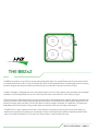
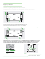
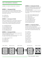
light. Four powerful light sources gives the
om the four blended sources shows no
we have all come to understand from this
mina. It's one of the highest power point
urate colours that makes our colour mixing
cations gives a tighter tolerance and
nce from the BB 4 possible. Daylight
s not need a nudge from amber to
hich makes one wonder if the source is
light. Four powerful light sources gives the
the the
feelfour
of the
fixturesources
when wishing
to
om
blended
shows no
fixtures.
Different
modes
we
have all
come tooperating
understand
fromensure
this
amp on full @ 240 volts.
mina. It's one of the highest power point
urate colours that makes our colour mixing
BB4 USERS MANUAL - PAGE 5
cations gives a tighter tolerance and
nce from the BB 4 possible. Daylight
s not need a nudge from amber to
hich makes one wonder if the source is
the feel of the fixture when wishing to
fixtures. Different operating modes ensure
i-PIX
BB4 washlight
THE
BB2x2
2
BB
4 Washlight
User
Manual
BB2x2
The BB 24 washlight provides the user with an energy saving hig
The BB2x2 provides the user with an energy saving high power lig
feel
and look of a modern light fixture. LED in origin, the appea
of a modern light !xture. LED in origin, the appearance from the fo
visible
appearance of existing led technology yet has the perfo
led technology yet has the performance we have all come to unde
novel form of light.
The
BB 224 washlight
washlight,isisequipped
equipped
with
four
custom
Engine
two
The BB
with
two
custom
lightLight
engines.
Its
source
ledIt light
It is the
homogenized
of colou
the t
available.
is theavailable.
homogenized
source
of the threesource
saturate
so good.
The performance
toto
i-pix’s
exacting
colour
s
The
performanceofofthese
theselight
lightengines
engines
i-pix's
exacting
colou
colour performance,
which makeswhich
tungsten
lighting
performance
improved
colour performance,
makes
tungsten
lightingf
also be found with ease and !nally a !xture that does not need a
temperatures can also be found with ease and finally a fixture
believable and full of low power energy, which makes one wonder
compensate. The whites are believable and full of low power e
really an led engine.
The BB2x2 has a super smooth control with 16 bit resolution, en
emulate the tungsten performance you would expect from pre ex
The
hasWith
a super
smooth control
bit!xture
resolution,
easeBBof24use.
consumption
of 120 with
watts,16the
drawsen
1
emulate the tungsten performance you would expect from pre
ease of use. With consumption of 120
60 watts, the fixture draws
7
BB
BB2x2
BB7
contents
contents
INTRO, RIGGING, SET UP & MODES
INTRO, RIGGING, SET UP & MODES
SAFETY FIRST
SAFETY
THE
BB7FIRST
THE
BB7
RIGGING
RIGGING
SET
UP
SET
UP
MODES
MODES A GRAPHICAL OVERVIEW
MODES
MODES A GRAPHICAL OVERVIEW
page 3
page 53
page
page 65
page
page 76
page
page 87
page
page 12
8
page
page 12
OPERATING INSTRUCTIONS
OPERATING INSTRUCTIONS
STAND ALONE FUNCTIONS
STAND ALONE
FUNCTIONS
STORING
A DMX
INPUT AS A MEMORY
STORING AADMX
INPUT AS A MEMORY
CREATING
MEMORY
CREATING
A
MEMORY
RECALLING A MEMORY
RECALLINGAACHASE
MEMORY
CREATING
CREATING A CHASE
page 13
page 13
13
page
page 14
13
page
page
14
page 17
page 18
17
page
page 18
THE TECHNICAL STUFF
THE TECHNICAL STUFF
CELL ORIENTATION
TECHNICAL
SPECIFICATIONS
TECHNICAL
SPECIFICATIONS
TROUBLE SHOOTING
TROUBLE
SHOOTING
QUICK RESET
QUICK RESET
page 24
page
20
page
20
23
page 23
page
23
26
page 25
page 28
25
APPENDICES
APPENDICES
APPENDIX 1
APPENDIX 1
APPENDIX 2
APPENDIX 2
ROHS COMPLIANCE
ROHSWEEE
COMPLIANCE
AND
DIRECTIVE INSTRUCTIONS
AND
WEEE
DIRECTIVE
INSTRUCTIONS
SERVICE CONTACT
DETAILS
SERVICE CONTACT DETAILS
page 26
page 27
26
29
page
page 30
27
BB7 USERS MANUAL - PAGE 2
BB2x2
BB7 USERS MANUAL - PAGE 2
SAFETY FIRST
WARNING!
Read the safety precautions in this section before
installing, powering, operating or servicing the BB4
2x2
The following symbols are used to identify important safety information in this manual:
Warning!
Safety hazard.
Risk of severe
injury or death
Warning!
LED light
emission. Risk
of eye injury
Warning!
Hazardous
voltage. Risk
of lethal or
severe
electric shock
Warning!
Fire hazard
! Read this manual before installing, powering or servicing the fixture, follow the
safety precautions listed below and observe all warnings in this manual. If you
have questions about how to operate the fixture safely, please contact I-Pix.
Warning! Class 2M LED product. Do not look into the beam from a
distance of less than 40 cm (16 inches). Do not stare into the beam
for extended periods at a short distance. Do not view the beam
directly with optical instruments.
This product is for professional use only. It is not for household
use. This product presents risks of severe injury or death due to fire
hazards, electric shock and falls.
BB2x2
MANUAL
3 3
BB4
USERS
MANUALPAGE
- PAGE
BB2USERS
USERS
MANUAL
PROTECTION FROM ELECTRIC SHOCK
Shut down power to the entire installation at the building’s main power distribution board and lock
out power (by removing the fuse for example) before carrying out any installation or
maintenance work.
Disconnect the fixture from AC power before removing or installing any cover or part
and when not in use.
Disconnect the fixture from AC power before removing or changing the fuse.
Always ground (earth) the fixture electrically.
Use only a source of AC power that complies with local building and electrical codes and has both
overload and ground-fault (earth-fault) protection.
Connect this fixture to AC power either using the supplied power cable or via 3- conductor cable
that is rated minimum 20 amp, hard usage. Suitable cable types include
ST, SJT, STW, SEO, SEOW and STO.
The voltage and frequency at the power outlet are the same as the voltage and frequency applied
to the power inlet. Only connect devices to the power outlet that accept this voltage & frequency.
Before using the fixture, check that all power distribution equipment and cables are in perfect
condition and rated for the current requirements of all connected devices.
Do not use the fixture if the power cable or power plug are in any way damaged, defective or wet,
or if they show signs of overheating.
PROTECTION FROM FIRE
Do not attempt to bypass thermostatic switches or fuses. Replace defective fuses with ones of
the specified type and rating only.
Provide a minimum clearance of 0.1 m (4 in.) around fans and air vents.
Do not modify the fixture
Apart from I-PIX accessories do not stick filters, masks or other materials directly onto the light.
PROTECTION FROM INJURY
when
Do not hang fixtures from each other. Use two OMEGA clamps per fixture or
I-PIXrigging
SINGLE
or
DOUBLE
YOLKS
when
suspending.
horizontally.
When suspending the fixture, ensure that the structure and all hardware used can hold at least
10 times the weight of all devices suspended from them.
Use two secondary attachments (such as a safety cable) to secure each fixture.
Secondary attachments must be able to hold at least 10 times the weight of all devices
suspended from them and must be installed as described in this manual.
Check that all external covers and rigging hardware are securely fastened.
Block access below the work area and work from a stable platform whenever installing,
servicing or moving the fixture.
The LED emission presents a hazard to eyesight at a distance of 4 - 40 cm (1.6 -16 inches)
when the eye is exposed to the beam for longer than 0.25 seconds.
Do not look at LEDs from a distance of less than 40 cm (1 ft. 4 in.) without suitable
protective eye wear.
Do not look at LEDs with magnifiers or similar optical instruments that may concentrate the
light output.
BB2x2
USERS
MANUAL
PAGE
4 4
BB4
USERS
MANUAL
- PAGE
BB2
USERS
MANUAL
i-PIX
BB4 washlight
i-PIX
BB4 washlight
BB4 washlight
BB 4 Washlight
The BB 4 washlight provides the user with an energy saving high power light. Four powerful light sources gives the
feel and look of a modern light fixture. LED in origin, the appearance from the four blended sources shows no
visible appearance of existing led technology yet has the performance we have all come to understand from this
novel form of light.
The BB 4 washlight, is equipped with four custom Light Engines from Lamina. It's one of the highest power point
source led light available. It is the homogenized source of the three saturate colours that makes our colour mixing
so good.
BB 4 Washlight
The performance of these light engines to i-pix's exacting colour specifications gives a tighter tolerance and
improved colour performance, which makes tungsten lighting performance from the BB 4 possible. Daylight
temperatures can also be found with ease and finally a fixture that does not need a nudge from amber to
compensate. The whites are believable and full of low power energy, which makes one wonder if the source is
really an led engine.
The BB 4 washlight provides the user with an energy saving high power light. Four powerful light sources gives the
The
BB 4look
has aofsuper
smooth
with
resolution,
enhancing
the the
feelfour
of the
fixturesources
when wishing
to
feel and
a modern
lightcontrol
fixture.
LED16
inbit
origin,
the appearance
from
blended
shows no
emulate
the tungsten
performance
you wouldyet
expect
from
pre existingwe
fixtures.
Different
modes
visible appearance
of existing
led technology
has the
performance
have all
come tooperating
understand
fromensure
this
ease
use.ofWith
novelofform
light.consumption of 120 watts, the fixture draws half and amp on full @ 240 volts.
The BB 4 washlight, is equipped with four custom Light Engines from Lamina. It's one of the highest power point
source led light available. It is the homogenized source of the three saturate colours that makes our colour mixing
BB4 USERS MANUAL - PAGE 5
so good.
i-PIX
BB2x2
2
BBTHE
4 Washlight
The BB 24 washlight provides the user with an energy saving high power light. Four
Two powerful light sources gives the
The BB2x2 provides the user with an energy saving high power light. Four powerful light sources gives look and feel
two blended sources shows no
feel and look of a modern light fixture. LED in origin, the appearance from the four
of a modern light !xture. LED in origin, the appearance from the four blended shows no visible appearance of existing
visible
appearance
of
existing
led
technology
yet
has
the
performance
we
have
all come to understand from this
led technology yet has the performance we have all come to understand from this novel form of light.
novel form of light.
The
BB 224 washlight
washlight,isisequipped
equipped
with
four
custom
Engines
from
It'spower
one ofpoint
the highest
power
two
The BB
with
two
custom
lightLight
engines.
Its one
of Lamina.
the highest
light source
ledpoint
light
source
led
light
available.
It
is
the
homogenized
source
of
the
three
saturate
colours
that
makes
our
colour
mixing
available. It is the homogenized source of the three saturate colours that make our colour mixing so good.
so good.
The performance
toto
i-pix’s
exacting
colour
speci!cations
givesgives
a tighter
tolerance
and improved
The
performanceofofthese
theselight
lightengines
engines
i-pix's
exacting
colour
specifications
a tighter
tolerance
and
colour
performance,
which
makes
tungsten
lighting
performance
from
the
BB2x2
possible.
Daylight
temperatures
improved colour performance, which makes tungsten lighting performance from the BB 24 possible. Daylight can
also be found with ease and !nally a !xture that does not need a nudge from amber to compensate. The whites are
temperatures can also be found with ease and finally a fixture that does not need a nudge from amber to
believable and full of low power energy, which makes one wonder if the source is really an led engine.
compensate. The whites are believable and full of low power energy, which makes one wonder if the source is
really an led engine.
The BB2x2 has a super smooth control with 16 bit resolution, enhancing the feel of the !xture when wishing to
emulate the tungsten performance you would expect from pre existing !xtures. Different operating modes ensure
The
hasWith
a super
smooth control
bit!xture
resolution,
the@feel
the fixture when wishing to
easeBBof24use.
consumption
of 120 with
watts,16the
drawsenhancing
1 amp on full
240ofvolts.
emulate the tungsten performance you would expect from pre existing fixtures. Different operating modes ensure
ease of use. With consumption of 120
60 watts, the fixture draws half and amp on full @ 240 volts.
BB2x2
MANUAL
PAGE
5 5
BB4USERS
USERS
MANUAL
- PAGE
Rigging a BB43 horizontally
ging
a Rigging
BB4
horizontally
ntally
a BB4
horizontally
Rigging
aa BB2x2
2 the
BB4
horizontally
To rig
ahorizontally
BB43 horizontally
use
OMEGA brackets supplied with the lamp.
gntally
a BB4
Rigging
a
BB4
horizontally
These would have your clamp of choice bolted on to them.
TheTo
obrackets
each
ohorizontally
each
obrackets
end
oeach
end
each
&ets
obe
the
end
&
each
end
the
aets
middle
&
&
middle
the
end
the
middle
obe
&
of
each
the
of
the
the
o
middle
end
lamp
of
of
lamp
the
each
&
the
using
the
lamp
of
using
end
lamp
the
middle
&the
using
&
the
lamp
the
using
the
camlocs.
middle
cof
the
middle
using
the
the
ctmiddle
cend
of
lamp
ofthe
c&
the
using
lamp
lamp
the
using
using
ccamlocs.
the
the
c cthe
The
OMEGA
brackets
can
be
attached
to
each
end
&end
the
middle
of
the
lamp
using
the
OMEGA
can
ets
can
can
attached
be
be
can
attached
attached
tmiddle
attached
tbrackets
toeach
ets
ets
to
can
each
can
tached
be
be
end
attached
attached
to
&
each
the
tthe
the
of
the
middle
lamp
of
using
the
lampc using the c
aorizontally
BB4
horizontally
use
OMEGA
brackets
supplied
with
the
lamp.
GA
brackets
use
To
supplied
the
OMEGA
with
the
lamp.
supplied
OMEGA
with
the
brackets
lamp.
supplied
with
the
lamp.
rig
aaBB2x2
horizontally
use
the
OMEGA
brackets
supplied
with
the
lamp.
rig
BB4
use
the
OMEGA
supplied
with
the
lamp.
2the
horizontally
GA
brackets
use
To
supplied
rig
the
achoice
OMEGA
BB4
with
horizontally
the
brackets
lamp.
use
supplied
the
OMEGA
with
the
brackets
lamp.
supplied
have
your
clamp
of
choice
bolted
on
them.
have
ewould
bolted
your
on
clamp
These
to
them.
of
bolted
on
to
them.
choice
bolted
on to
to them.
them. with the lamp.
would
have
your
clamp
of to
choice
bolted
on
e
have
bolted
your
on
clamp
These
to
them.
of
would
choice
have
bolted
your
on
clamp
to
them.
of
choice
bolted
on
to
them.
MEGA
canmiddle
be attached
each
end
& the
of the
lamp
using
the
camlocs.
to
rackets
eachbrackets
can
endThe
be
& the
attached
toofeach
theto
end
lamp
&using
the
attached
middle
the
camlocs.
tomiddle
ofeach
each
the end
lamp
end
&using
the
middle
the
camlocs.
of
the
lampusing
usingthe
thecamlocs.
camlocs.
OMEGA
brackets
can
be
attached
to
&
the
middle
of
the
lamp
brackets
to each end
canThe
&
bethe
attached
OMEGA
middlebrackets
toofeach
the lamp
end
can &
be
using
the
attached
middle
the camlocs.
to
ofeach
the lamp
end &using
the middle
the camlocs.
of the lamp using the camlocs.
First
place
the
pins
in
the
receptacles
with
the
levers
facing
out
place
thecamloc
camloc
amloc
amloc
pins
pins
amloc
in
in
in
recept
pins
the
recept
amloc
inturn
recept
the
receptacles
amloc
pins
amloc
in
pins
the
pins
receptacles
in
with
in
the
the
the
recept
recept
with the levers facing out
First
acles
with
acles
the
acles
with
the
with
the
rthe
levers
levers
fthe
acles
flevers
acles
acles
facing
the
with
with
levers
out
the
the
facing
levers
levers
flev
out
fwise.
s awith
quarter
alevers
quarter
turn
clock
turn
swise.
afwith
quarter
clock
swise.
aer
quarter
turn
wise.
turn
clock
clock
turn
wise.
clock
wise.
then
to secure
the
s aacles
brackets
quarter
sspins
turn
athe
giv
quarter
clock
clock
wise.
then to secure the brackets give the levers a quarter turn clock wise.
ace
thewith
camloc
pins
inthe
thecamloc
receptacles
with
leversout
facing
place
pins
inin
the
receptacles
with
the
ptacles
camloc
pins
First
the
ininthe
levers
receptacles
facing
out
the
levers
receptacles
facing
out
with
the
levers
facing out
out
he
ptacles
camloc
with
pins
First
the
levers
the
place
receptacles
the
facing
camloc
outwith
with
pins
the
levers
thethe
receptacles
facing
without
the levers
levers facing
facing
out
o
secure
the
brackets
give
levers
a
quarter
turn
clock
wise.
to
secure
the
brackets
give
the
levers
a
quarter
turn
clock
wise.
e
vers
the
a
brackets
quarter
then
give
turn
the
clock
levers
wise.
a
quarter
turn
the
clock
levers
wise.
a
quarter
turn
clock
wise.
evers
re theabrackets
quarter
then
turn
give
to the
clock
secure
levers
wise.
theabrackets
quarter turn
give clock
the levers
wise.a quarter turn clock wise.
t
igh
AL
el
Make absolutely sure all four attachment points are secure BEFORE
t shrigging the lightthALWAYS secure the lamp to
g safety
origging
absolutely
sure
all
four
attachment
points
are
secure
BEFORE
rigging
the
light
ALWAYS
secure
the
utely
ent
points
sure
all
are
four
Make
secure
attachment
absolutely
BEFORE
points
sure
rigging
all
are
four
the
secure
light
attachment
ALWAYS
BEFORE
points
rigging
secure
are
the
secure
lamp
light
ALWAYS
to
BEFORE
secure
rigging
the
lamp
to
ALWAYS
the
absolutely
all
four
attachment
points
arethe
secure
BEFORE
lamp
to
rtosecure
ent
ely sure
points
allare
Make
foursecure
attachment
points
are
attachment
ALWAYS
points
rigging
secure
lamp
light
ALWAYS
to lamp
rigging
secure
the
lamp
light
ALWAYS
tolamp
secure
the
lamp
to
wn the
the
truss,
pipe
e.t.c. sure
with
two
safety
bonds.
One
attached
to the
through
the
point
shown
inlamp
fig 1to
inlight
h
g
t
i
n
uss,
pipe
e.t.c.
with
two
safety
bonds.
One
attached
to
the
lamp
through
the
safety
point
shown
in
fig
1
onds.
e.t.c.
One
with
attached
the
two
truss,
safety
pipe
bonds.
e.t.c.
One
through
with
attached
two
the
safety
safety
the
bonds.
point
lamp
One
through
shown
in
the
fig
safety
1
to
the
point
lamp
shown
in
fig
1
point
shown
in
fig
1
L
g
truss,
pipe
e.t.c.
with
two
safety
bonds.
One
attached
to
the
lamp
through
the
safety
fig
1
f
epe
onds.
e.t.c.
One
with
attached
the
two
safety
to
the
bonds.
lamp
One
attached
safety
to
safety
bonds.
lamp
point
One
through
shown
attached
in
the
fig
safety
1
lamp
point
through
shown
in
the
fig
safety
1
point
shown
in
fig
1
r
i
ached
toother
the yolk
through
point shown
in figpoint
2 NEVER
thrin fig 2 NEVERr through
yoke.
g 2 tht A othe
the
attached
to the safety
yolk through
the safety
shown
or
the brackets.
uERgto
h E Vor
Ethethrough
hched
the
safety
the
point
the
yolk
other
shown
through
attached
inthe
the
figsafety
safety
NEVER
thepoint
point
yolk
through
shown
through
in
to
the
fig
the
2safety
brackets.
point
shown
or
in
toto
fig
the
brackets.
htotthe
her
attached
to
the
yolk
through
the
safety
pointor
in
figpoint
2 through
NEVER
through
to
brackets.
the
other
attached
yolk
through
safety
shown
fig
22or
htached
the
safety
totothe
point
yolk
through
shown
in
fig
22toto
NEVER
the
through
through
shown
orshown
inthe
the
to
fig
the
safety
2 NEVER
NEVER
brackets.
point
through
shown
orin
in
fig
the
2NEVER
NEVER
brackets.
through
orto
thebrackets.
brackets.
igN
l
p
R
E
V
O tahme 2 N ER th he saf
l
r
ineg
g
iggth n fi thr
r
oug
E
i R
ho
OR o n EVE
w2 N
rt
o
hig
f
s
n
n ti
w
ho
ts
fig 2
fig
fig 22 fig 2
fig fig
fig
2 fig
fig2222
fig
2
t shown in fig 2 NEVER through torshown
to theinbrackets.
fig 2 NEVER thr
Mak
ettachmen
ttachmen
lutely
absolut
sur
utely
sur
fig fig
1fig11fig
fig 2
2
fig 2
g11 fig 1
BB4 USERS MANUAL - PAGE
BB4 USERS
6BB4 USERS
MANUAL
- PAGE
BB4
USERS
6- PAGE
MANUAL
---PAGE
BB2x2
USERS
PAGE
6 6
MANUAL
6
USERS
MANUAL
PAGE
BB4
USERS
MANUAL
66
BB2
USERS
MANUAL
BB3
USERS
MANUAL
BB4 USERS MANUAL - PAGE
BB4 USERS
6
MANUAL
-BB4
PAGE
BB4
USERS
6 MANUAL
MANUAL
-PAGE
PAGE
6
2 vertically
Rigging
BB4
Rigging a BB2x2
vertically
To rig a BB4 vertically use the SINGLE or DOUBLE YOLK hanging brackets. The brackets can be supplied as
accessories for the lamp. You would obviously have your clamp of choice bolted on to them.
The YOLK brackets can be attached to the top, middle or the lamp using the camlocs.
To
vertically useuse
one one
of the
brackets
supplied
with thewith
lamp.the lamp.
To rig
rigaaBB2x2
BB 2 horizontally
ofOMEGA
the OMEGA
brackets
supplied
These would have your clamp of choice bolted on to them.
First place the camloc pins in the receptacles with the
The OMEGA bracket can be attached to the side of the lamp using the camlocs.
figfig1 2
fig 2
Make
Makeabsolutely
absolutelysure
sureallallfour
fourattachment
attachmentpoints
pointsare
aresecure
secureBEFORE
BEFORErigging
riggingthe
thelight
lightALWAYS
ALWAYSsecure
securethe
thelamp
lamptoto
the
truss,
pipe
e.t.c.
with
two
safety
bonds.
One
attached
to
the
lamp
through
the
safety
point
shown
in
fig
the truss, pipe e.t.c. with two safety bonds. One attached to the lamp through the safety point shown in fig11
the
theother
otherattached
attachedtotothe
theyolk
yolkthrough
throughthe
thesafety
safetypoint
pointshown
shownininfigfig22NEVER
NEVERthrough
throughorortotothe
thebrackets.
brackets.
WRONG
MANUAL
PAGE
6 BEFORE rigging the BB4
Make absolutely sureBB4
bothUSERS
attachment
points- are
secure
light. USERS MANUAL - PAGE 6
ALWAYS secure the lamp to the truss pipe e.t.c. with two safety bonds as shown on the previous page.
First place the camloc pins in the receptacles with the levers facing out
First place the camloc pins in the receptacles with the levers facing out
then to secure the brackets give the levers a quarter turn clock wise.
then to secure the brackets give the levers a quarter turn clock wise.
These would have your clamp of choice bolted on to them.
The OMEGA brackets can be attached to each end & the middle of the lamp using the camlocs.
The OMEGA brackets can be attached to each end & the middle of the lamp using the camlocs.
levers facing out the correct way.
Then to secure the brackets turn the levers a quarter
cure BEFORE
rigging
lightattachment
ALWAYS secure
theare
lamp
to BEFORE rigging the light ALWAYS secure the lamp to
turn
clock
wise.
Make
absolutely
sure the
all
four
points
secure
First
place
the camloc
pins inpoint
the receptacles
with
the levers facing out.
ed
to
the
lamp
through
the
safety
shown
in
fig
1
he truss,Then
pipe to
e.t.c.
withthe
two
safety bonds.
One
attached to the lamp through the safety point shown in fig 1
secure through
brackets
give
the
levers a quarter turn clockwise.
shown
in
fig
2
NEVER
or
to
the
brackets.
he other attached to the yolk through the safety point shown in fig 2 NEVER through or to the brackets.
BB2USERS
USERS
MANUAL
BB2x2
MANUAL
7 7
BB4
USERS
MANUALPAGE
- PAGE
SET UP
1. Select appropriate dimmer curve
The
offers
a choiceofoftwo
twodimmer
dimmer curves.
curves
The BB2x2
BB4 offers
a choice
1 LINEAR - the output increases directly with dmx input.
2 ENHANCED - the first 10% of the output is controlled over the first 50% of the DMX input.
First press the button under the MORE legend.
4INVRT1 ADDR 001
MODE 3 5CH MORE
PRESS
PRESS
Then press the PROFILE button.
Then select the appropriate dimmer curve.
linear LIN.
PROFILE
MAN
CHASE
STORE
PRESS
CURV-LIN BACK ON
PRESS
Or enhanced ENH.
2 Disable or enable user interface backlight
Whilst in PROFILE you may choose to switch off the user
interface backlight. When you press the button above BACK
ON the legend will change to BACK OF and the backlight will
go out 5 seconds after the interface is last used, though the
backlight will come back on whenever any button is pressed.
When you press the button above BACK OF the legend will
change to BACK ON and the backlight will remain lit
constantly.
CURV-ENH BACK ON
BACK ON shows the current status
of the backlight
PRESS
CURV-LIN BACK ON
PRESS
CURV-LIN BACK OF
BB2x2
MANUAL
PAGE
8 9
BB2USERS
USERS
MANUAL
BB4
USERS
MANUAL
- PAGE
8
3 Select appropriate operating mode
The
gives
you you
a choice
of ten of
operating
modes. These
modes
2 will
TheBB2x2
BB4
gives
a choice
ten operating
modes.
These modes
will enable you to set up the lamp in the most appropriate way for the
many different jobs the lamp will be used for. The nuts and bolts of the
modes are described in detail in pages 12 to 15.
To select a mode
Keep the button below the MODE legend depressed go
through the modes, just before the one you desire stop,
then press once.
4INVRT1 ADDR 001
MODE 1 3CH MORE
PRESS
4 Select appropriate DMX address
PRESS
First press the button above the ADDR legend.
Then change the address using the 100s,10s & 1s buttons.
4INVRT1 ADDR 111
MODE 1 3CH MORE
PRESS
100s
10s
ADDR 011
1s
BB2
MANUAL
BB4USERS
USERS
MANUALPAGE
- PAGE
9
BB2x2
USERS
MANUAL
9 10
press the button above 4INVRT1.
Keep the button below the MODE legend depressed go
2 the
The BB4
will modes,
gives you
a choice
operating
modes.
through
just
before of
theten
one
you desire
stop, These modes
will enable
you to set up the lamp in the most appropriate way for the
then
press once.
many different jobs the lamp will be used for. The nuts and bolts of the
56 locking off the interface
modes
described in detail in pages 12 to 15.
5 inverting
the cells
5 inverting
theare
cells
4INVRT1 ADDR 001
MODE 1 3CH MORE
PRESS
When you are satisfied that you have set up all the lamp’s parameters to your liking it is possible to lock off
4 Select
appropriate
DMX
the
that
you the
dont
inadvertently
anything
when
focusing
etc.
Should you
wishinterface
to
change
running
order
ofaddress
the
cells
so
instead
running.
Should
you
wishsotothe
change
running
order
ofchange
thethat
cells
so thatof
instead
of running.
To select a mode
Keep the button below the MODE legend depressed go
through the modes, just before the one you desire stop,
then press
press the
once.
First
button above the ADDR legend.
To lock off the interface depress the MORE and ADDR
buttons simultaneously and the MORE will change to LOCK.
they run they run
4INVRT1 ADDRPRESS
001
MODE 1 3CH MORE
1234
1234
4 Select appropriate DMX address
4321
4321
Then change the address using the 100s,10s & 1s buttons.
To unlock
the
interface
depress
thethe
LOCK
andlegend.
ADDR buttons
First
press
the
button
above
ADDR
Press
button
above
1NORM4
Press
the
button
above
1NORM4
simultaneously
and
thethe
LOCK
will
change
to MORE.
1NORM4
002
4INVRT1
ADDR 111
PRESS
9 20CH
MODE 1
3CH MORE
1NORM41NORM4
shows the
current
shows
thePRESS
current
orientation
of the cells.
orientation
of the cells.
PRESS
PRESS
PRESS
PRESS
1NORM4 1NORM4
ADDR 002ADDR 002
MODE
9 20CH MORE
MODE 9 20CH
MORE
100s
1NORM4 ADDR
002
4INVRT1
ADDR011
111
10s 1
1sMORE
9 20CH
LOCK
MODE
3CH
PRESS
THIS
IS AN EXTREMELY
USEFUL FUNCTION
IF SOMEONE
HASTHE
RIGGED
THEWAY
WRONG
WAY ROUND!
THIS IS AN
EXTREMELY
USEFUL FUNCTION
IF SOMEONE
HAS RIGGED
LAMPTHE
THELAMP
WRONG
ROUND!
Then change the address using the 100s,10s & 1s buttons.
return
To returnTo
them
to them to
1234
1234
PRESS
PRESS
100s
ADDR
011 - PAGE 11
BB4
USERS
MANUAL
10s
PRESS
1s
4INVRT1 4INVRT1
ADDR 002ADDR 002
MODE MORE
9 20CH MORE
MODE 9 20CH
the
button
above 4INVRT1.
press thepress
button
above
4INVRT1.
locking
off the interface
6 locking6 off
the interface
When
you are that
satisfied
that you
have
all the
lamp’s parameters
to your
it istopossible
When you
are satisfied
you have
set up
all set
theup
lamp’s
parameters
to your liking
it is liking
possible
lock offto lock off
the
interface
so
that
you
dont
inadvertently
change
anything
when
focusing
etc.
the interface so that you dont inadvertently change anything when focusing etc.
PRESS
Tothe
lockinterface
off the interface
depress
MORE
To lock off
depress the
MOREthe
and
ADDRand ADDR
buttons simultaneously
and the
willtochange
buttons simultaneously
and the MORE
willMORE
change
LOCK. to LOCK.
PRESS
1NORM4 1NORM4
ADDR 002ADDR 002
MODE
9 20CH MORE
MODE 9 20CH MORE
PRESS
PRESS
BB2
MANUAL
BB4USERS
USERS
MANUAL - PAGE 10
9
PRESS
unlock
the interface
depress
ADDR buttons
To unlockTothe
interface
depress the
LOCKthe
andLOCK
ADDRand
buttons
simultaneously
and
the
LOCK
will
change
to
MORE.
simultaneously and the LOCK will change to MORE.
PRESS
1NORM4 1NORM4
ADDR 002ADDR 002
MODE LOCK
9 20CH LOCK
MODE 9 20CH
PRESS
PRESS
BB2
MANUAL
BB4USERS
USERS
MANUAL - PAGE 10
9
BB2x2
USERS
MANUAL
PAGE
10 11
10
BB4MANUAL
USERS
MANUAL
- PAGE
BB2
USERS
MANUAL
BB4 USERS
- PAGE 11
THE OPERATING MODES
MODE 4 - 9 channels 16 bit
The BB2x2
has10
10 different
different operating
modes
to suittodifferent
The
BB4 has
operating
modes
suit different
uses, programming styles and dmx configurations.
Ideal for fast programming or limited dmx line
space with overall dimming & strobe control
and a greater resolution in control over the
dimming and colours.
All 4 cells are treated as 1 with the 5 channels
dim, strobe, red, green & blue affecting the
whole lamp.
MODE 1 - 3 channels 8 bit
The most simple, ideal for fast programming or limited
dmx line space and as a node on a media server. All 4 cells
are treated as 1 with the 3 channels red, green & blue
affecting the whole lamp
ch1 - master intensity high byte all cells
ch2 - master intensity low byte all cells
ch3 – strobe all cells
ch4 – red high byte all cells
ch5 - red low byte all cells
ch6 – green high byte all cells
ch7 - green low byte all cells
ch8 – blue high byte all cells
ch9 - blue low byte all cells
ch1 - red all cells
ch2 - green all cells
ch3 – blue all cells
MODE 2 - 6 channels 16 bit
Ideal for fast programming or limited dmx line space and
as a node on a media server, with a greater resolution
over the colours. All 4 cells are treated as 1 with the 6
channels red, green & blue affecting the whole lamp.
MODE 5 - 12 channel 8 bit
ch1 - red high byte all cells
ch2 - red low byte all cells
ch3 - green high byte all cells
ch4 - green low byte all cells
ch5 - blue high byte all cells
ch6 - blue low byte all cells
Ideal for use with media servers where dmx
line space may be a consideration.
MODES A
Each cell can be individually coloured with its
own red green blue channels. (most useful
when each cell is patched individually -3ch)
MODE 3 - 5 channels 8 bit
Ideal for fast programming or limited dmx line space with
overall dimming & strobe control.
All 4 cells are treated as 1 with the 5 channels dim, strobe,
red, green & blue affecting the whole lamp
ch1 - master intensity all cells
ch2MODES
- strobe allA
cells
GRAPHICAL
ch3 - red all cells
ch4 - green all cells
ch5 - blue all cells
Mode 1
- 3 ch
Mode
1 8 bit
Mode Mode
1 3ch 1
8 bit
R
OVERVIEW
Mode
Mode22- 6 ch 16 bit
3 ch 8 bit
Mode
2 6ch 16 bit
Mode
6 ch 216 bit
3 ch 8 bit
6 ch 16 bit
r
r
g
g
r
b
b
g
Mode 5
R
R
G
G
B
B
GR
BG
Mode 6
r
R
g
ch1 - red cell 1
ch2 - green cell 1
ch3 - blue cell 1
ch4 - red cell 2
ch5 - green cell 2
ch6 - blue cell 2
ch7 - red cell 3
ch8 - green cell 3
MASTER
STROBE
ch9 - blue cell
3
INTENSITY
CHANNEL
ch10 - red cell 4
ch11 - green cell 4
ch12 - blue cell 4
r rgg
5 chR
8 bit
R bbR r
r
gg
r gg
R
GG
r bG
R
b b
g
g Br BG
G
Mode 3 - 5 ch 8 bit
Mode
3 5ch 8 bit
ModeMode
3
5 ch 8 bit
GbBb
Mode 7
Mode 4
9 ch 16 bit
rrR
R
ggRG
Mode
4 - 94ch 16 bit
Mode
g16 5bit
g
Moder4 9ch
Mode
9 ch 16
bit
R
R12bRch 8 bit
R
r Gg
GGGr g
bb
BB
Br Brgbg
GbbGB
GRAP
R
Mode 1
M
1
3 Mode
ch 8 bit
Mod
6c
3 ch 8 bit
6 ch 1
r
GR
g
r
b
g
b
BG
B
RR
Mode
5 - 12
Mode
5 ch 8 bit
Mode 5 12ch 8 bit
g
12 ch r8 bit
b
r g
r g
r gb
b
rr gg brr gg
r g
r g
b
bbg
b
g
r
b
Mode
6
g
r
rb
bg
gg
rrr24bgggch 16brrrbit
r g r gr g
bbg b rbbbg
rb
rrr bggg rrr bggg
R G
M
RR24GGc
RB G
B
R BG
B
RRR GGG
RB G
RB
BG
Mo
B
RRRR GGGG
14 ch
R G
GG
BB
B
BB
r g
bb B bb
b
BB2x2
MANUAL
PAGE
11 12
BB4USER
USERS
MANUAL
- PAGE
G
R
Mode r8 g
RRR GGG
r
Mod
r
MODE 6 - 24 channel 16 bit
MODE 8 - 27 channel 16 bit
High resolution colour control over each individual
cell with a strobe and a high resolution master
intensity having overall control over all 4 cells.
Ideal for use with media servers, with a greater
resolution over the colours.
Each cell can be individually coloured with its own red
green blue channel. (most useful when each cell is
patched individually -6ch)
ch1 - red high byte cell 1
ch2 - red low byte cell 1
ch3 - green high byte cell 1
ch4 - green low byte cell 1
ch5 - blue high byte cell 1
ch6 - blue low byte cell 2
ch7 - red high byte cell 2
ch8 - red low byte cell 2
ch9 - green high byte cell 2
ch10 - green low byte cell 2
ch11 - blue high byte cell 2
ch12 - blue low byte
cell 2
MODES
ch13 - red high byte cell 3
ch14 - red low byte cell 3
ch15 - green high byte cell 3
ch16 - green low byte cell 3
ch17 - blue high byte cell 3
ch18 - blue low byte
cell 31
Mode
ch19 - red high byte cell 4
1
3 Mode
ch
ch20 - red low byte
cell84bit
ch21 - green high byte cell 4
3 chcell
8 bit
ch22 - green low byte
r 4
ch23 - blue high byte cell 4
ch24 - blue low byte cell
g 4
A
ch1 - master intensity high byte all cells
ch2 - master intensity low byte all cells
ch3 - strobe all cells
ch4 - red high byte cell 1
ch5 - red low byte cell 1
ch6 - green high byte cell 1
ch7 - green low byte cell 1
ch8 - blue high byte cell 1
ch9 - blue low byte cell 1
ch10 - red high byte cell 2
ch11 - red low byte cell 2
ch12 - green high byte cell 2
ch13 - green low byte cell 2
ch14 - blue high byte cell
2
MASTER
STROBE
GRAPHICAL OVERVIEW
INTENSITY
CHANNEL
ch15 - blue low byte cell
2
ch16 - red high byte cell 3
ch17 - red low byte cell 3
ch18 - green high byte cell 3
ch19 - green low byte cell 3
ch20 - blue high byte cell 3
Mode 2
Mode 3
Mode 4
ch21 - blue low byte cell 3
- red high byte
cell 44
Mode
Mode
Modech22
3 5 ch
Mode
6 ch 216 bit
8 bit
9 ch 16
bit 5
ch23 - red low byte cell 4
byte
12 ch 8 bit
6 ch 16 bit
5 ch 8 ch24
bit - green high
9 ch
16cell
bit 4
r
ch25 - green low byte cell 4
R
R
ch26 - blue high byte cell 4
g low byte cell 4
ch27 - blue
G
G g
r
R
g
R
G
r
MODE 7 - 14 channel
8 bit R
b
B
g
BG
Colour control over each individual cell with a master
intensity and strobe having overall control over all 4 cells.
b
ch1- master intensity
all5cells
Mode
ch2 - strobe all cells
ch3 - red cell 1 12 ch 8 bit
ch4 - green cell 1
r g
ch5 - blue cell 1 r g
b
ch6 - red cell 2rr g
g rr bgg
g
ch7 - green cell 2r g
bbgMode 6rrbbbg
ch8 - blue cell 2 rb
bg
gg
gg
ch9 - red cell 3rrr bg
rrrbit
24
ch
16
ch10 - green cellr 3g
r g
bbg
bbg
ch11 - blue cell 3rb
rb
ch12 - red cell r
4r bg
r gg rrr bggg
ch13 - green cell 4 R G
b B bb
ch14 - blue cell 4b
B
G
R bRr
R G
b
R
Mode 6
rR
R
gG
GbbB
r rgg
R bR
g
rR
Gg
Gr
bb
Br g
Br B
Ggb
R
GbBb
rrR
rbgg
RR
R
g
R
rg
g
GG
G
G
B
Mode 7
RR24 GchMode
R bit
6G
- 24 ch 16 bit 14 ch
Mode
7 - 14 ch 8 bit
G
16R16
8 bit
Mode
6
24ch
Mode 7 14ch
8 bit
G
RB
RB Gbit
B
B
R BG
R BG
r g
B
B R G
bg
G
G
RRR GG RRR GG B
g
r g
RBBG
RBBG
bbbg
R Mode
Mode r8
7 R BG R G
BG
B
B B
g
r bg
RRRR GGGG RRRR GGGG
27
ch
16
bitg
14 ch
8
bit
G
r g
R G
R GR
G
BB
B
B
rr
BB
B
B
RRR GGG RRR GGGR G
B
r g
bb B
R G
Bg
r rgg
R
R bbR
g
rg
R
GG
r bbG
g
g Br BG
b
Mode
r g9
r g20 chb8 bit
b r g
r
R
r g
RRbRrg
r g
r g g
r
rr bggb
r g
bbgr gMode 9
rb
b
rrr bggg20g ch 8 bit
r gr
bbg b
rb
rrr bggrg g
b r g
r g
b
Mode r8 g
b
RR27GG8ch- 27
RRchbitG16
Mode
bit
16
Mode 8 27ch 16Gbit
RB G
RB G
RB
RB
BG
BG
r
R
g
r rg
R
b
RR
RRR GG RRR GG
g
RB r R
B gRBB
G GG
RRR GG bRRR GG
BB
BB
BG B
RR Gr
GgRgR GG
R GB
B
G
G
R G
R G
R GR 10
R B G Mode
BG
B B
B
G
G
R G
36 ch R
16Gbit
R G R GR G
B B
B
B
rr b
bbg
rb
g
gg B
rrr bgr
R G
b
bb
B b
B
GG
R G
r Bg
bBb
b
g 10
r Mode
R G
BB2x2
USER
MANUAL
PAGE
g
B
- PAGE
gb USERS
r 12g 13
r RBB4
GG
RRbitMANUAL
R36GGch 16
RRGb
R bRrBBgG RBBGbR
R
rRb G bRrg R r
R
GbbB
R G R GR G
RB G
B
RR r
R G
R G
r
R
MODES A GRAPHICAL OVERVIEW
MASTER
STROBE
INTENSITY
CHANNEL
MODE 10 36 channel 16 bit
MODE 9 20 channel 8 bit
R
rRr
R
gG
gR
rR
R
gG
Gb B
R
rrR
R
ggRG
R
Ideal for control over all aspects of programming
Mode 4
with high resolution
intensity, high
r gg Moderesolution
gmaster
r 16r
g
Mode
4
colour
9 ch control
bit 5and a strobe control over
each individual cell.
useful when each cell is
bbR 9 ch 16patched
bch(most
R
R
12R
8 bit
bit individually
- 9ch).
r
R
ERVIEWr
R
ghigh byte cell 1
r gg
rg
R
ch1 - master intensity
gch1- master intensityGall cells 1
G1GG
GG
g cell 1
r byte
ch2 – strobe cell
low
- strobe all cells 1
b
rbch2
r
b
Rch2 – strobe cell 1B b
RB
ch3 - red cell 1
b
ch4 - red high byte cell
r g1
ch4 - green cell 1
ch5 - red low byte
cell
gb1
Br B
Br Bg ch6
3 cell 1
Mode 4
G
ch5 - blue
gMode
g
green
high
byte
cell 1
G
G
gg intensity
r
g
ch6- master
all cells 2 r g
g1
b
r
ch7 - green low byte cell
Mode
Mode 3 5 ch 8 bit
9 ch 16
bit 5
r
ch7 - strobe allMode
cells42
R
b 1
ch8 - blue high byte cell
b
ch8b
- red cell 2
R
b
R12Rchb8 bit Mode 7
ch9 - blue low byte
5 ch 8 bit
bit 6
r8 g1
Mode 5R
Mode
Modecell
B
bch9r- green9cellchR216B
gb high
ch10 - master intensity
byte cell 2
R
g
r
r
g
G
G
R
ch10
blue
cell
2
G
GG byte cell 2
R
R
G
G
R24 ch 16Rbit r R
Gch 16Rbit
12 chr8 bitg
14 ch 8 bit
ch11 - master
low
R27intensity
g
G 3 g
RB G allRB
g master intensity
ch11cells
G
RBcell
BBG
ch12 – strobe
2 R
b
B
G
G GG
g rR
RB
RB
b
r
G
R
R
G
G
R
g
g
g
B
B
r g G
r
r
- strobe all cells 3
R bg ch13 - red highBGbyteRcellBG2
B
B
b
rrr bgg ch12
b
R
b
b
b
G
G
R
R
g
g
ch13
red
cell
3
RRR byte
RRR 2GG
rrb g
rr g ch14 - red low
RR GG RR GG
GG cell
Br g rrr gg g
RB3G
RB G
r g ch14
r -ggreen cell
r g
G
ggRRBcell
BBGr byte
B10
bbgMode
bbbg
bbbr
bbbg Modech15
- greenR
2
RB
RB
Mode r8
Rhigh
BG
BG B B
6
Mode
7
9
Mode
g
g
rb
r
r
B
B
B
g
B
ch15 - blue cell 3B
r
G
b
r
G
G
Gr gg ch16 - greenRRRlowGGGbyte
G
cell 2
B
grrr24bgggch ch16gg
gg b rr bg
r bg
r bg
GGGG 4
RRRRGGGGG all
RRRRcells
RRRRcellGGG2
r
r
master intensity
b
r
r
R
g
27
ch
16
bit
B
ch17
blue
high
byte
b
r
16 rbitg
14 ch
36 ch 16 bit
r g ch17
r g
r g20 ch 8 bit
G 84bitRB G
RB
RB
- strobe allRBcells
B
B
B
B2
b
b
b
b
ch18
blue
low
byte cell
b
b
b
b
b
B
r bg ch18
r b-gred cell 4 B
r bg
r bg
B
intensity
high byte cell 3
grrr bggg ch19 - master
B
BggRR low
br
gg B
GG
RRR Gr
RRRB
rrr 7bg-gggreen cell
GG R
G R
ch19
4G
RR GGG Mode r8 g rrr g
brrrbbgggRMode
ch20
master
intensity
byte cell 3
g
g
r
g
r
G
G
G
g
r
R
bR b
r
ch20
blue
cell
4
g
b
b
b 14Bch 8bbit
b b ch21 – strobe cell 3 cell
RR27GGch 16
RRbitBGG b
B
b
ch22 - red high byte cell 3
RB G
RB G
Mode
bRRRBB G
gch2310
RB
r g9
r Mode
R
Rg Gb
rR
r g
B
- red low byteRcellG 3
R
g
B
B
B
b
b
b
g3
b
g
rrcell
Grghigh byte
RR
RgR GGG RR
-R
green
rRr GgGG r R rrRR36GGch24
rr ggrr g20 chR
R
R
8R
bit rR
chR
16
bitG
RrrrbRgrbgRgrgG Mode
r g
RB G
RRB
b
G
g
G
G
g
b
b
g
ch25
green
low
byte
cell
3
R
R
g
r
b
r
g
r
G
G
B
B
R
R
R
b
b36
b20r chg 98 bitr gRRMode
bbg9R-Mode
10R
chR16 bit R R BG
B
B
Mode r8b
R- B
bgB
rb
BG Mode
BB10
B
B G high byteBcell 3
ch26 -Rblue
b
b
G
G
G
B
B R
R
g
R
g
rr gg3
bg
r Rg Gch27R- blue
R
gR
g
glow byte G
gbgg rr bgg
rrRR GggGG g
gb rrr bgggR
R
GGG bRR
r
GGG
Rg
rrrbit
r
cell
g
g
g
r
g
g
R
r
g
R
R
r
r
G
r
G
G
R
g
R
R
g
R
R
g
G
R
R
g
G
g
g
27 ch
16
G
G
r
G
G
G
r
rRBB36 chRRr16RRBbBBGGbit Rb R
rbbRB Gch28R-RG
R rGb
G
R
G rbbRbgGrB rbbg20Grrbbchgrbb8gbitR
G
G
r gG
R
Gb
master
intensity
high
byte
cell
B
b
b
b
b
R intensity
B
R R BBbGch29 -Rmaster
RB low byte cell 44
R bB
bgb
R
g
r bR
r bgR b r bg b rb
BG
B
BG
rr gg
BrG BgRgBR
B Bg
r RggBGch30R– strobe
BG
G
g
BG
bg
rrRR GggG R
rr rrgggr bggg rrr bgggB
g
ggR
g
r bg
R
R
G
gBg
R
B
r
r
G
Rg
G
rrrB
r
cell
4
g
g
r
R G
G
G
R
R
R
R
R
R
G
G
r
G
R
R
G
G
G
R g
gGb B
b
B
Gg
Gg
bbRRBBGch31B
gG
G
G
G
b
B
b
B
Gb
G
GB b
Rred
RG
G
b
-G
high byte cellb 4
Brrbbbggg
B
B RGBBGBbbgbGb bb Ggbbbrgrrbbbbggg BGG
b
B
b
B ch32 - red
B low byte cell 4
B
r r bg
R G
B
BG
b
g
g4
g
r
B
B
r
r cell
g
ghigh byte
g B
gg 10
G
r
r brrrg Mode
rr ggB
GGG
GGGB
R
g
g
ch33RR
-Rgreen
B
G
G
R
g
R
R
R
G
G
G
G
B
R
G
RB
G
G
R
g
g
G
G
Bbg b B b ch34B-Bgreenblow bytebcell 4 B
G
G
brRggbbbGG BRR
BB
g
bB
g
b
B
BG
b
B
bbGr
B
b
r
r
b
BbrB
B
g
r
B
rRb G R
B
r
G
R36 chR
Rbit
R
R
16
r
ch35 - blue high byte cell 4
bR G b
b
G
G
g
R
R
B
b
r
G
B
B
R
b
R
R
GGR
R
R
b
g
g
ch36 - blue low byte cell 4
G
RB
RB
BrG B GG
B
BG
B
b
B
G
B
B
BB
B
B
R
g
R
B
rr gg
R
r Rgg G R Gg
R
b
bB
g
BbR
b
g
g
g
rg
g
g
G
r
r
G
GG R
GG
grrG
R
R
R
R
G
R
R
G
g
G
G
GR
r
r
G
G
R
R
R
rbbB bR G R bbRBBbG RBBGbbR RBrGbb
R BG
R BG
R
B
B
g
rr gg
B
B
B Bg
B
r
G
g
B
G
rr g R
g
g
R
R
g
G
R
r
G
G
G
R
R
R
G
G
G
G
G
R
R
R
R
G
G
R
R
g
g
g
g
B
B
G
G
Gg
b Gb Gb GG
B
B Gb Gb
Mode 1
Mode 2
Mode 3
Ideal for control over all aspects of programming
where
space 2may be a consideration.
1 dmx line Mode
Mode 3 5 ch 8 bit
3 Mode
ch 8 bit
6 ch 16 bit
For each cell there is individual control over master
strobe
and
mixing.
3 chintensity,
8 bit
6 ch
16red
bit green colour
5 ch
8 bit (most
MASTER
STROBE
useful when each cell is patched individually -5ch).
G
INTENSITY
rRr B
R
gG
gR R
GbBbG G
rRr B
R
gGgR
R
R
R
R
R
R
R
R
RR
R
G
G
g
g
g
g
g
g
g
g
g
G
G
G
G
G
G
G
G
b
B
G
G
G
b
G
G
G
G
G
R
BBB
R
RGbRgBbbG
bgbg
b
bBbB
B
G
G
G
G
G
GGBbGB
G
G
BBB
bbGbbBBbGbBbbB
GbGb
B
bb B
Mode 9 20ch 8 bit
CHANNEL
GbBbG
rR
R
g G rRr
R
R
g
g
Gb B G
G
G
rrR bBb
R
ggRG
GbbGB
B
G
B
G
G
BG
B
G
G
B
G
BG
B
G
G
B
G
G
Mode 10 36ch 16 bit
G
B
G
B
G
G
BG
B
G
G
B
G
BG
B
G
G
B
G
G
GbbGB
R
G
B
OPERATING
BB2x2
USERS INSTRUCTIONS
MANUAL PAGE- Page
14 11
b bB B
b b
Br g Bg
G
B
RB Gb
bRBBG
B
B
B
Br Rg GG R GGBg
RR G RR G
G
G Gb
Bb b
B
G
BB b
b
Br g
Gb
B
OPERATING
BB2x2
USERS INSTRUCTIONS
MANUAL PAGE- Page
14 11
BB2x2
MANUAL
13 14
BB4 USER
USERS
MANUALPAGE
- PAGE
G
B
G
B
MODES A GRAPHICAL OVERVIEW
R
Mode 1
Mode 2
1
3 Mode
ch 8 bit
6 ch 16 bit
r
R
GRG
g
rb
B
g
G
B
b
B
G
R
Mode 5
Mode 6
RR24 Gch 16
RRbitGG
RB G
RB G
RB
RB
BG
BG
12 ch 8 bit
r g
r g
rr bgg rr bgg
r g
r g
b
bbg
b
r bgMode 6rb
rrr24bgggch 16rrrbitbggg
r g
r g
b
bbg
b
r bg
rb
rrr bggg rrr bggg
R G
bb
bb
B
B
RRR GGG
RB G
B
RRR GGG
RB G
B
BB
B
BB
B
G
R Mode
7 R BG
BG
B
B
RRRR GGGG RRRR GGGG
14 ch
R G 8 bitR G
B
RRR GGG RRR GGG
r g
bb B
B
R G
Bg
R RbRrG
b
Mode
r g9
r g20 chb8 bit g
R b r g r g r gbR
b
b
bg g
g
r g
Gr rrgr ggr grrr ggGg
R bb rbbbg b rbbbgbbR
RR r
r
R
gr
g
R
gR
g
r
r
GR
G G
G
R
R
R
R
R
BG
R
R
R
R
R
r rrggr gg rrr ggB
g
R
R
B
R
g
g
r
R
R
G
G
g
g
g
g
gG
gGGBG
g
gG
g
g
g
B
G
r
r
B
b
GG
GG b rbb GGBrbbbGb
G
G
BbGbG
G
G
B
R
R
B
B
BG
b
b
b
B
r rrgr gg rrr ggB
b
b
B
g
g
b
B
R
b
B
R
G
g
g
G
G
R
B
g
g
G
G
G
G
GB
GBbBG
BB
b bb BBbb b
B
B
b
bB
bG
B
BG
B
G
G
G
G
G
G
B
B
g
R
g Gb
Grb
b
b
B
Gb
B
bbRB
RrB
b
G
BG Bb
BBB
Bb bB b
B
R
R
R
R
g
g
g
g
GRGRGG GG
Bgb gGb GB
G
G
G
G
Bbb bBb BB
R G
bB
R RG Gb
R
BRB
B
B
bg
g
bg
bg
STROBE
INTENSITY
rRr
R
gG
gR
gg
r
Mode 3 5 ch 8 bit
bR
5 ch 8 bit R b
r
r gg
GG
r bb
g Br Bg
CHANNEL
rR
R
gG
GbbB
Mode 3
Mode
6 ch 216 bit
3 ch 8 bit
MASTER
bg
g
bg
bg
b
GbBbG
rrR
rbgg
RR
R
g
R
rgg
GG
G
Mode 7
14 ch 8 bit
r g
rr bgg
r g
bbbg
Mode r8
bg
gg
rrrbit
27 ch 16
r g
bbg
rb
rrr bggg
R G
Mode 4
g5
r
g
Mode
9 ch 16
rb bit
R12Rch 8 bit
R
g
rg
R
GGGr g
bb
Br g
Br B
Ggb
Mode 4
9 ch 16 bit
R
G
r g
b
Mode r8 g
b
RR27GGch 16
RRbitGG
RB G
RB G
G
RB
RB
B
BG
B
r
R
g
r rg
R
b
RR
RRR GG RRR GG
RBBr R
ggRBB
g
G
GG
RRR GG bRRR GG
BB
BB
BG B
RR Gr
GgRgR GG
r g
rr bgg
r g
bbg Mode 9
rb
rrr bggg20 ch 8 bit
r g
bbg
rb
rr bggg
B
B
G
G
R G
R G
G
R B G Mode
R B10
B
B
G
R G
G36 ch R
16Gbit
R G
R G
B
B
b
Br Bgr
B
R G
r Bg
GbBbG
bb
R
rRb G r R r RR r
R
B
R
R
R
R
g
rg
g
g
g
g
r
r
r
G
R
G
GR
r
G
G
R
R
R
rbbB
G
R
BG
B
g
B
rr gg R
g
R
G
R
rr RRRRgg GG BRRRR GGg
G
R
G
g
g
B
G
b
g
GG
GG
b b
B Gb
b
Br g
g
bR
g
G
b
R
Bg
G
b
Bg
G
B
B
G
G
R
b BBG
B
B
G
G
RB Gb
B
B
BG
r RRRg GG RRR GGB
g
G
G
G
Bb b B b BB b
G
GbbB
R G
g
bb r b
g 10
r Mode
bG R G g
r RRg36
Gch 16RbitG
G
g
R
b
r
B
R R BG RRBBGGbR
B
B
b
B
B g
g
r
Gr RRRgr GgGG RRR GGGGg
G
G
R bbRRBBBbG RRBBBGbbR
G
R G
R G
B
R G
B
r g
rb
RRG
B
R
rr gg
g
G
R rGb
RB b
B
rr gg
G
R
b
Gg
b
Br g
Gb
R
R
G
G
B
B
OPERATING
BB2x2
USERS INSTRUCTIONS
MANUAL PAGE- Page
14 11
Stand alone functions
The
able to
to run
alone
mode
without
any need
data from
a lighting
Thedesk.
light isThe light is
TheBB2x2
BB42 isisable
runinina astand
stand
alone
mode
without
anyofneed
of data
fromconsole.
a lighting
capable of outputting up to 20 programmable memories and 1 chase that steps through these memories.
“The light must be in MODE 3 (5ch) for all the stand alone functions to work.”
Storing a DMX Input as a Memory
However if you have access to a lighting desk a quick and easy way to create multiple or complex
memories is to give the light the desired colour information using a lighting desk or similar DMX
generating device and use the STORE function.
1 Connect the light to the desk in the usual way making sure the address is correct and the lamp is in MODE 3.
2 Create the desired colour on the lighting desk.
3 Press the button underneath the MORE legend once.
4INURT1 ADDR 001
MODE 3 5CH MORE
PRESS
4 Press the button underneath the STORE legend once.
PROFILE
MAN
CHASE
STORE
PRESS
PRESS
5 You should then assign this memory a number using the
UP, DOWN buttons.
6 When you are happy this memory has been numbered
correctly press the STORE button wait 3 seconds and the
display will return to the main menu.
UP
DOWN
MEN 04
STORE
UP
DOWN
MEN 04
STORE
PRESS
BB2
MANUAL
BB4USERS
USERS
MANUALPAGE
- PAGE
15
BB2x2
15 16
Creating a memory
1 press the button underneath the MORE legend once.
4INURT1 ADDR 001
MODE 3 5CH MORE
PRESS
2 press the button underneath the MAN (manual)
legend once.
PROFILE
MAN
CHASE
STORE
PRESS
3 press the button underneath the PROG MEM
(program memory) legend once.
USE MEM PROG MEM
PRESS
You are now presented with the first variable of your
memory which is the Master Intensity (MINT).
The default value for the MINT is 100% - intensity full.
If you wish to alter this value use the buttons above and
below the UP & DOWN legends until you have the
desired % value.
UP MINT 100%
DOWN
UP MINT 080%
DOWN
PRESS
PRESS
4 When happy with the MINT value press the button
above MINT once.
UP MINT 080%
DOWN
Next you are presented with STRB (strobe) the second
variable of your memory which has a default value of
0% - no strobe.
UP
DOWN
STRB 080%
In the same way if you wish to alter this value use the
UP & DOWN buttons to give you the desired % value.
BB2x2
MANUAL
16 17
BB4USERS
USERS
MANUALPAGE
- PAGE
BB2
USERS
MANUAL
16
PRESS
5 When happy with the STRB value press the button above STRB once.
UP
DOWN
STRB
Now you are presented with the first colour RED (default 0%).
UP
DOWN
RED
000%
In the same way if you wish to alter this value use the UP, DOWN
buttons to give you the desired %. If you require 100% press the
DOWN button.
UP
DOWN
RED
100%
000%
PRESS
PRESS
6 When happy with the RED value press the button above RED once.
UP
DOWN
RED
100%
Next you are presented with the second colour GREEN (default 0%)
In the same way if you wish to alter this value use the UP, DOWN buttons to give you the desired %
If you require 100% press the DOWN button.
PRESS
7 When happy with the GREEN value press the button above
GREEN once.
UP
DOWN
GREEN000%
Finally you are presented with the third colour BLUE (default 0%).
In the same way if you wish to alter this value use the UP, DOWN buttons to give you the desired %.
If you require 100% press the DOWN button.
PRESS
8 When happy with the BLUE value press the button above
BLUE once.
UP
DOWN
BLUE 000%
BB2x2
MANUAL
17 18
BB4USERS
USERS
MANUALPAGE
- PAGE
BB2
USERS
MANUAL
17
Now you are given the opportunity to store your
memory If you are satisfied with all the values you
have inputted.
If however you think you may have made a mistake or
you have just changed your mind then you can return
to the start of the memory by pressing MEM button
and repeating the above process.
If you are happy with you memory you should then
assign it a number using the UP, DOWN buttons.
9 When happy with your memory number press STORE.
UP
DOWN
MEM 01
STORE
PRESS
UP
DOWN
MEM 01
STORE
PRESS
UP
DOWN
MEM 04
STORE
UP
DOWN
MEM 04
STORE
PRESS
BB2x2
MANUAL
18 19
BB2
USERS
MANUAL
BB4USERS
USERS
MANUALPAGE
- PAGE
18
To Recall A Memory
1 Press the button underneath the MORE legend once then.
4INURT1 ADDR 001
MODE 3 5CH MORE
PRESS
2 Press the button underneath the MAN (manual) legend once then.
PROFILE
MAN
CHASE
STORE
PRESS
3 Press the button underneath the USE MEM (use memory) legend.
USE MEM PROG MEM
PRESS
Now you will be offered the first memory MEM 01.
This will come on automatically.
UP
DOWN
MEM 01
STORE
PRESS
4 To select any other memory simply use the UP, DOWN buttons until
you find the memory you want.
UP
MEM 01
DOWN DMX MODE
The memories will come on as you select them.
“ IF YOU WISH YOUR MEMORY TO COME ON AS SOON AS YOU GIVE
THE LAMP POWER YOU WILL NEED TO PROGRAMME IT AS A TWO
STEP CHASE WITH BOTH MEMORIES HAVING THE SAME VALUE”
To return to the main menu press the DMX MODE button
UP
MEM 02
DOWN DMX MODE
PRESS
BB2x2
MANUAL
19 20
BB4USERS
USERS
MANUALPAGE
- PAGE
BB2
USERS
MANUAL
19
Programming a Chase
1 Ensure you have programmed all the memories that will go to make up the steps of your chase.
2 Press the button underneath the MORE legend once..
4INURT1 ADDR 001
MODE 3 5CH MORE
PRESS
PRESS
3 Press the button above the CHASE legend once.
Now the WAIT TIME will appear this is the first variable of
the chase to be set. The WAIT TIME is the time period
between cross fades that the colour is held constant for.
PROFILE
MAN
CHASE
STORE
UP WAIT TIME
DOWN
001s
PRESS
Select the appropriate time (in seconds) using the UP, DOWN buttons.
UP WAIT TIME
DOWN
002s
PRESS
4 When you are happy with the WAIT TIME press the button above
WAIT TIME once.
Now the XFADE TIME (cross fade time) will appear this is the
second variable of the chase to be set. The XFADE TIME is the
length of time the light takes to change from one colour to another.
UP WAIT TIME
DOWN
002s
UP XFADE TIME
DOWN
002s
PRESS
Select the appropriate time (in seconds) using the UP, DOWN buttons.
UP XFADE TIME
DOWN
003s
PRESS
5 Once you are happy with the XFADE TIME press the button above
XFADE TIME once.
UP XFADE TIME
DOWN
003s
BB2x2
MANUAL
PAGE
20 21
20
BB2
USERS
MANUAL
BB4USERS
USERS
MANUAL
- PAGE
Now CHASE STRT (chase start) will appear along with the option MEM 1.
This will be the first step of your chase.
Choose which memory you would like to be the first step of your chase
using the UP, DOWN buttons.
6 Once you are happy with the memory that will be your first step
press the button above CHASE STRT.
Now CHASE END will appear along with the option MEM 1.
This will be the last step of your chase.
The chase will run through all the memories numbered between the
first and last step.
PRESS
UP CHASE STRT
DOWN MEM 01
UP CHASE END
DOWN MEM 01
PRESS
Choose which memory you would like to be the last step of your chase
using the UP, DOWN buttons.
UP CHASE END
DOWN MEM 02
PRESS
7 Once you are happy with the memory that will be your last step
press the button above CHASE END once.
Now you will be offered the option USE CHASE, if you wish to simply
press yes.
The Interface will now say CHASE RUNNING.
When you wish to end or change the chase press MENU.
UP CHASE END
DOWN MEM 03
USE CHASE
YES
NO
PRESS
CHASE RUNNING
MENU
PRESS
If you leave a chase running when the light is powered down the chase will resume as soon as the light is
powered back up again.
! If the chase does not run try rerecording the first step again
BB2
USERS
MANUAL
BB2x2
MANUAL
21 22
BB4USERS
USERS
MANUALPAGE
- PAGE
21
Stand alone functions
BB2x2 cell orientation
The BB7 is able to run in a stand alone mode without any need of data from a lighting desk. The light is
capable of outputting up to 20 programmable memories and 1 chase that steps through these memories.
“The light must be in MODE 3 (5ch) for all the stand alone functions to work.”
Storing a DMX Input as a Memory
However if you have access to a lighting desk a quick and easy way to create multiple or complex
memories is to give the light the desired colour information using a lighting desk or similar DMX
generating device and use the STORE function.
1 Connect the light to the desk in the usual way making sure the address is correct and the lamp is in MODE 3.
2
2 Create the desired colour on the lighting desk.
1
3 Press the button underneath the MORE legend once.
MODE 3
ADDR 001
5CH MORE
PRESS
3
4 Press the button underneath the STORE legend once.
4
UP
DOWN
MEN 01
STORE
PRESS
PRESS
5 You should then assign this memory a number using the
UP, DOWN buttons.
6 When you are happy this memory has been numbered
correctly press the STORE button wait 3 seconds and the
display will return to the main menu.
UP
DOWN
MEN 04
STORE
UP
DOWN
MEN 04
STORE
PRESS
BB7 USERS MANUAL - PAGE 22
13
BB2x2
BB 4 Washlight tech spec
BB2x2 Technical Speci!cations
Dimensions
Dimensions:
Length
600 mm
Length
355
Height
301 mm
onmm
rubber feet
Height
291 mm
Width
147 mm
Width
178 mm
Weight
13.5Kg total
Weight
7.93Kg
Yoke:
3 KG
Power Box:
4.5Kg
Mechanical design & materials:
BB4 batten:
6Kg
Batten
aluminium shrouded "nned diagonal heatsink
Yoke
folded and welded steel
Mechanical
design/
materials
used
Finish
Electro static powder coated black satin
Batten
Power box
Rigging:
Yoke
Style
Finish
Number of positions
Accessory holder
Conventional mounts
Rigging
!Style
Aluminium shrouded finned diagonal heatsink
Aluminium with steel base
Folded12!
and#welded
steel fasteners
turn camloc
Electro9static
powder
coated
black satin
rigging
locations
on yoke
"tted with sprung retention $ap
2 of 12mm bolt holes "tted at each yoke end
Note:
unit comes
with two Omega rigging brackets to accept 12mm bolts,
16 ¼ turn
camloc
fasteners
Number of positions
Electrical:
Accessory holder
Input
Conventional
mounts
8 rigging locations on yoke
Fitted with sprung retention flap
90- 265
50/60
Hzat each yoke end
2 of 12mm
boltVolt
holes
fitted
Input
Output
Control:
Fixture feed
Fixture feed
DMX channels
Mains
and data
User interface
Input
Data inline
type female
Output
Output:
Chassis mounted male IP67 6 pin
Chassis mounted female IP67 6 pin
Chassis mounted female IP67 7 pin
RGB additive colour mixing
Trailing 7 pin male
Current
ampsto@accept
240 volts
Note:
unit comes with three scaffold clamp0.25
adaptors
12mm bolts, equipped with
Power
60 watts total power on full @ 240 volts
two
camloc ¼ turn bolts
Fuse
20mm x 5mm slow blow 2 amp
Input
trailing male IP67 6 pin ( Combined power and data connection )
Electrical
connections for mains andchassis
data mounted
in/out female IP67 6 pin ( Combined power and data connection )
Output
Combined power and data connection Note; units comes complete with 16 amp plug and 5 pin male.
Electrical
Source
120
watts total power on full.
Optics
Input
Power characteristics:
Thermal
Fuse
Output
to fixture
Operating
temperature!
3 channels minimum 18 channels maximum
backlit lcd display with four membrane switches
6 pin Ceep
USITT DMX512-A
6 pin Ceep
customised RGB LED light engine
2 x 20° optics with 10°,35° & 45° also available
90- 265"Volt 50/60 Hz
0.5 amps @ 240 volts
20mm force
x 5mm
blow
amp
4
airslow
cooled
via 2
low
air$ow/ low noise fans
15 voltsMinimum:
max -20 degrees C, Maximum:+ 46 degrees C
Rated to IP65
Weather
protection:
Data type
USITT DMX512-A
Humidity
20%
~ 90%
non-condensing
Note;
unitsmax
comes complete with 16 amp
cee
formRH
plug
and 5 pin xlr male. A 1
!
metre combined power cable link is also supplied.
BS EN 55103-1!!!!! ! Harmonics
Approvals & Compliance:
Control RGB additive colour mixingBS EN 55103-2!!!! !! Immunity
DMX channels
User interface
BS EN
61000-3-2!!!
Emissions
3 channels
minimum
36 channels
maximum
weatherproof
backlit lcd display
with
USA / Canada!!!!!!!!
ETL
pending
four membrane
switches
"
BB2x2
USERS
MANUAL
22 23
23
BB4
USERS
MANUALPAGE
- PAGE
BB2 USERS
USERS
MANUAL
BB2x2
MANUAL
PAGE
22 22
Modes
8 bit
1
3
5
7
9
standard resolution
1 x RGB over 4 cells
1 x RGB over 4 cells with an overall master and strobe
4 x RGB
4 x RGB with an overall master and strobe
4 x RGB each with individual master and strobe
16 bit
2
4
6
8
10
high resolution (recommended)
1 x RGB over 4 cells
1 x RGB over 4 cells with an overall master and strobe
4 x RGB
4 x RGB with an overall master and strobe
4 x RGB each with individual master and strobe
note 16 bit for every channel bar strobe which runs as 8 bit
Note; please refer to power box or user instructions or website for channel allocation details. Most
popular lighting desks have personalities available for download from their respective websites or the
downloads section on our website.
Light Engine
Source
Wavelengths
Optics
Customised lamina Titan RGB LED
Red
625 Nm +/- 2.5 Nm
Green 517 Nm +/- 2.5 Nm
Blue 452.5 Nm +/- 2.5 Nm
4 x evenly spaced 20 degree optic
note: further photometric data and IES files are available for download from our website
Thermal characteristics
Fixture front
Power box
Passive convection cooled
Force air cooled via low airflow/ low noise fans, mounted to the base
Operating temperature
Minimum
Maximum
Weather protection
Fixture front
Power box
Humidity max
-20 degrees C
+ 46 degrees C
Hermetically sealed to IP67
Mounted horizontally facing upwards
Rated to IP65H
20% ~ 90% RH non-condensing
Approvals & Compliance
BS EN 55103-1 Harmonics
BS EN 55103-2 Immunity
USA / Canada ETL pending
Lead and mercury free return to manufacturer for recycling
IP Protection
BS EN 61000-3-2 Emissions
Patents filed in USA
Manufactured in the United Kingdom by
We reserve the right to improve this fixtures design.
BB4 USERS MANUAL - PAGE 24
24
BB2x2 USERS MANUAL PAGE 25
24
TROUBLE SHOOTING
DISCLAIMER: Please note that the information contained in this trouble-shooting guide is generalized in nature & cannot
account for all possibilities. Any proposed remedies for specific situations should not be considered as absolute or all
encompassing. Please seek professional assistance if there is any doubt as to the efficacy of a remedy or of the exact nature of
any encountered problem. I-pix provides the information contained herein only as a guide.
No response from the light
Does the LCD
screen light up
No
Yes
Does the unit have
a good power supply
Yes
Is the LCD
screen flashing
Check the fuse
is it blown
No
Yes
Yes
There is no signal
check DMX input
Contact I-Pix for more specific help with
your problem, as it could be an
internal fault.
If you have the technical knowledge &
skills you could open up the unit & Yes
check for loose connections
Replace with the
appropriate fuse 4A
Mains supply keeps tripping out blowing fuses:
Does the mains
supply trip before
the light/s are
given power?
Yes
No
Contact I-Pix for more specific help with
your problem, as it could be an
internal fault.
If you have the technical knowledge &
skills you could open up the unit & check
for loose connections shorts & faults
Does the mains
supply trip when
the light/s are
given power?
Yes
No
Check all external
wiring for faults or
the supply overloaded.
If problem persists
contact a competent
electrician.
Is the mains supply
overloaded with the
addition of the
lamp?
Yes
Remove some of the
load from the supply
upgrade the supply
rating - split the load
across more circuits
No
When you try the
lamp on a different
supply does it work
Yes
Contact a competent
electrician to
check out the supply
that
could be faulty
BB4
USERS
MANUALPAGE
- PAGE
BB2 USERS
USERS
MANUAL
25
BB2x2
MANUAL
25 26
26
TROUBLE SHOOTING
The fuse on a unit repeatedly blows
•
•
•
Are you fitting right rating/type of fuse into unit?
Contact I-pix for more specific help with your problem, there may be an internal fault in the unit.
If you have the technical knowledge/skills you could look inside the unit and check the internal wiring for a lose
connections/shorts and also the power supply is working with a 15v output when
there is no load connected to it.
Dmx trouble shooting
The obvious
•
It is good practice to connect data line and terminate before switching on device.
•
Is the dmx line fitted to a buffer and data is being received
•
Is the dmx data line fitted with a line termination?
•
Does the unit’s dmx mode set-up match the personality/ profile for the console provided?
•
Note: the LCD screen flashes intermittently when no data is present
BB2x2
USERSMANUAL
MANUAL
2627
27
BB4USERS
USERS
MANUAL PAGE
- PAGE
26
BB2
QUICK RESET
An easy way of returning the light to its default settings.
PRESS
Before the light is given any power hold down both
both buttons on the left hand side of the interface.
PRESS
Keep the buttons held down as you give the light power.
When you see screen with the black boxes let go of
the buttons and the next screen will appear. If you
do not let go it will stay locked until you let go.
PRESS
PRESS
Then the light will return to MODE 10 ADDR 001
4INVRT1 ADDR 001
MODE10 18
36CH MORE
This is a fast way of readdressing a light, that will save you a few button presses
BB4USERS
USERSMANUAL
MANUALPAGE
- PAGE
BB2
27
BB2x2
USERS
MANUAL
2728
28
RoHS AND WARRANTIES
I-PIXBB2x2s
BB4s
RoHSRESTRICTIONS
RESTRICTIONS
2 COMPLY
I-PIX
COMPLYWITH
WITH RoHS
I-PIXBB2x2s
BB4s
with
of the
criteria
proposed
by the European
I-PIX
arecompliant
compliant with
all all
of the
criteria
proposed
by the European
2 are
RoHS directive 2002/95/EC for hazardous material content in electronic and
electrical equipment as listed in Annex 1A and 1B of the WEEE Directive.
In addition to containing no mercury, the LED light engines have the
following environmental advantages over traditional light sources:
!
High energy efficiency
!
Long lifetime
!
Fully dim-able
!
Very low IR and UV radiation
For attachment of electrical connections I-Pix use lead free solder
R
C
US
RoHS
2002/95/EC
COMPLIANT
WARRANTY STATEMENT
2 produced
I-Pix(seller)
(seller)
extends
warranty
the electronics
in the
BB4
by
I-Pix
extends
warranty
on allon
theall
electronics
in the BB2x2
produced
by
the Seller for two (2) years from original date of shipment, that the goods
sold hereunder are new and free from substantive defects in workmanship
and materials. This warranty extends only to the Buyer and not to indirect
purchasers or users . Sellers liability under the foregoing warranty is limited
to replacement of goods or repair of defects or refund of the purchase price
at the Sellers sole option. The above warranty does not apply to defects
resulting from the improper or inadequate maintenance, unauthorized
modification, improper use or operation outside of Sellers specifications for
the product, abuse, neglect, or accident. THE ABOVE WARRANTY IS
EXCLUSIVE AND NO OTHER WARRANTY, WHETHER WRITTEN OR ORAL, IS
EXPRESSED OR IMPLIED. I-PIX SPECIFICALLY DISCLAIMS THE IMPLIED
WARRANTIES OF MERCHANTABILITY AND FITNESS FOR A PARTICULAR
PURPOSE - I-PIX Jan 01, 2009
WEEE
COMPLIANT
WARRANTY STATEMENT
2 produced
I-Pix(seller)
(seller)
extends
warranty
the in
L.E.Ds
in theproduced
BB4
I-Pix
extends
warranty
on allon
theall
L.E.Ds
the BB2x2
by the by the
Seller for one (1) year from original date of shipment, that the goods sold
hereunder are new and free from substantive defects in workmanship and
materials. This warranty extends only to the Buyer and not to indirect
purchasers or users. Sellers liability under the foregoing warranty is limited
to replacement of goods or repair of defects or refund of the purchase price
at the Sellers sole option. The above warranty does not apply to defects
resulting from the improper or inadequate maintenance, unauthorized
modification, improper use or operation outside of Sellers specifications for
the product, abuse, neglect or accident. THE ABOVE WARRANTY IS
EXCLUSIVE AND NO OTHER WARRANTY, WHETHER WRITTEN OR ORAL, IS
EXPRESSED OR IMPLIED. I-PIX SPECIFICALLY DISCLAIMS THE IMPLIED
WARRANTIES OF MERCHANTABILITY AND FITNESS FOR A PARTICULAR
PURPOSE - I-PIX Jan 01, 2009
BB2x2
USERS
MANUAL
28
29
BB2 USERS
USERS
MANUAL
BB2x2
USERS
MANUAL -PAGE
PAGE
27
BB4
MANUAL
PAGE
29
28
SERVICE CONTACT DETAILS
Broadstone Mill
Broadstone Road
Houldsworth Village
Cheshire
SK5 7DL
[Located 4 miles from Manchester airport and the city centre]
Tel: 44 (0)161 443 4140
E-mail: [email protected]
www.i-pix.com
BB4
MANUAL PAGE
- PAGE
29
BB2x2
2930
BB2 USERS
USERS MANUAL
30