1
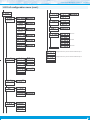
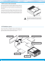
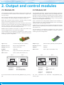
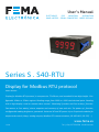
User’s Manual
ELECTRONICS
FOR
INDUSTRIAL
AUTOMATION
PANEL METERS . SIGNAL CONVERTERS . LARGE DISPLAYS
Series S . S40-RTU
Display for Modbus RTU protocol
PANEL meters
Display for Modbus RTU protocol, in compact size 72 x 36 mm, and standard 14 mm digit height. Configurable 16 bits or 32 bits register. Reading range from 9999 to -1999 with decimal point. Reading
with 4 digit display. Local or remote alarm control. ‘Watchdog’ function and ‘bus activity’ function.
Fast access to ‘bus ativity’, alarm setpoints and memory of max and min. ‘On power up’ function,
configurable reading brightness, password. Universal AC and DC power. Up to 2 optional modules for
output and control (relays, analog outputs, Modbus RTU communications, RS-485 ASCII, RS-232, ...)
www.fema.es
3724r02
Tel. (+34) 93.729.6004 [email protected]
FEMA ELECTRÓNICA . Series S . S40-RTU
1. Panel meter S40-RTU
Display for Modbus RTU protocol, with compact 72 x 36 mm size
Display for Modbus RTU protocol, in compact 72 x 36 mm size, and
14 mm standard digit height. Reading with 4 digits. Control for reading values and decimal point position by writing to the instrument
registers. Standard 16 bit Modbus RTU registers (values from 32767
to -32767, and display reading from 9999 to -1999) and configurable
to 32 bits registers (see section 1.13).
Local or remote alarm control with modes ‘Full slave’ (see section
1.2) or ‘Process slave’ (see section 1.3). In ‘Full slave’ mode alarm
state is controlled by writing to registers or coils (see section 1.14).
Bus speed configurable up to 38.400 bps and address configurable
from 1 to 247. ‘Watchdog’ function detects if communication with
the master is lost. ‘Watchdog’ function can display a message on display and control the activation of alarms (see section 1.15).
Function ‘bus activity’ is a utility for troubleshooting communications (see section 1.16). Function ‘On power up’ defines the alarm
state at start-up (see section 1.23.8).
In ‘Process slave’ mode 2 independent alarms are configurable by
the operator and are locally controlled by the instrument. Configured
as maximum or minimum alarms, with 1 or 2 setpoints each alarms,
hysteresis, activation and deactivation delays, inverted activation option and manual unlock option.
Options for output and control with 1 and 2 relays, isolated analog
outputs, communications in Modbus RTU, RS-485 ASCII and RS-232.
Special options with 4 relay outputs.
Front protection IP54. Connections by plug-in screw terminals. For
industrial applications.
• ‘Fast access’ menu to selected functions, accessible with key UP (5)
(see section 1.23.6)
• Function ‘On power up’ for system protection on first ‘cold’ startup or automatic reset (see section 1.23.8)
Memory for maximum and minimum reading, password protection,
5 brightness levels.
Index
1. Panel meter S40-RTU . . . . . . . . . . . . . . . . . . . . . . 2
1.1 How to order . . . . . . . . . . . . . . . . . . . . . . . . . 3
1.2 ‘Full slave’ mode . . . . . . . . . . . . . . . . . . . . . . . 3
1.3 ‘Process slave’ mode . . . . . . . . . . . . . . . . . . . . 3
1.4 Typical application . . . . . . . . . . . . . . . . . . . . . . 3
1.5 Front view . . . . . . . . . . . . . . . . . . . . . . . . . . 4
1.6 Power connections . . . . . . . . . . . . . . . . . . . . . 4
1.7 Start up sequence . . . . . . . . . . . . . . . . . . . . . . 4
1.8 Rear view . . . . . . . . . . . . . . . . . . . . . . . . . . . 4
1.9 Signal connections . . . . . . . . . . . . . . . . . . . . . 4
1.10 Technical specifications . . . . . . . . . . . . . . . . . . 5
1.11 Mechanical dimensions (mm) . . . . . . . . . . . . . . 5
1.12 Modbus RTU definitions . . . . . . . . . . . . . . . . . . 6
1.13 Registers with 16 bits or 32 bits . . . . . . . . . . . . . . 6
1.14 Alarm control : registers and coils . . . . . . . . . . . . 6
1.15 ‘Watchdog’ function . . . . . . . . . . . . . . . . . . . . 6
1.16 ‘Bus activity’ function . . . . . . . . . . . . . . . . . . . 6
1.17 How to operate the menus . . . . . . . . . . . . . . . . 7
1.18 Messages and errors . . . . . . . . . . . . . . . . . . . . 7
1.19 Registers and functions in ‘Process slave’ mode and 16 bits data . . 8
1.20 Registers and functions in ‘Process slave’ mode and 32 bits data . . 9
1.21 Registers and functions in ‘Full slave’ mode and 16 bits data . . . 10
1.22 Registers and functions in ‘Full slave’ mode and 32 bits data . . . 11
1.23 Configuration menu . . . . . . . . . . . . . . . . . . . 12
1.23.1 Initial set-up . . . . . . . . . . . . . . . . . . . . . 12
1.23.2 Bus configuration . . . . . . . . . . . . . . . . . . . 12
1.23.3 Configuration . . . . . . . . . . . . . . . . . . . . . 13
1.23.4 Alarms in ‘Full slave’ mode . . . . . . . . . . . . . 13
1.23.5 Alarms in ‘Process slave’ mode . . . . . . . . . . . 14
1.23.6 Fast access . . . . . . . . . . . . . . . . . . . . . . 15
1.23.7 Super fast access . . . . . . . . . . . . . . . . . . . 15
1.23.8 Menu ‘On Power Up’ . . . . . . . . . . . . . . . . . 15
1.23.9 Menu ‘Setpoint on bus’ . . . . . . . . . . . . . . . 15
1.23.10 Menu ‘Decimal point’ . . . . . . . . . . . . . . . 16
2
1.23.11 Menu ‘Key LE’ . . . . . . . . . . . . . . . . . . . . 16
1.23.12 Function ‘Password’ . . . . . . . . . . . . . . . . 16
1.23.13 Factory reset . . . . . . . . . . . . . . . . . . . . 16
1.23.14 Firmware version . . . . . . . . . . . . . . . . . . 16
1.23.15 Brightness . . . . . . . . . . . . . . . . . . . . . . 16
1.23.16 Access to optional modules . . . . . . . . . . . . 16
1.24 Factory configuration . . . . . . . . . . . . . . . . . . 17
1.25 Full configuration menu . . . . . . . . . . . . . . . . . 18
1.26 To access the instrument . . . . . . . . . . . . . . . . 20
1.27 Modular system . . . . . . . . . . . . . . . . . . . . . 20
1.28 Precautions on installation . . . . . . . . . . . . . . . 21
1.29 Warranty . . . . . . . . . . . . . . . . . . . . . . . . . 21
1.30 CE declaration of conformity . . . . . . . . . . . . . . 21
2. Output and control modules . . . . . . . . . . . . . . . . . 22
2.1 Module R1 . . . . . . . . . . . . . . . . . . . . . . . . . 22
2.2 Module AO . . . . . . . . . . . . . . . . . . . . . . . . . 22
2.3 Module RTU . . . . . . . . . . . . . . . . . . . . . . . . 23
2.4 Module S4 . . . . . . . . . . . . . . . . . . . . . . . . . 23
2.5 Module S2 . . . . . . . . . . . . . . . . . . . . . . . . . 24
2.6 Modules R2, R4 . . . . . . . . . . . . . . . . . . . . . . 24
3. Accessories . . . . . . . . . . . . . . . . . . . . . . . . . . 25
3.1 Option G . . . . . . . . . . . . . . . . . . . . . . . . . . 25
4. Other options . . . . . . . . . . . . . . . . . . . . . . . . . 25
4.1 Adapter KA72 . . . . . . . . . . . . . . . . . . . . . . . 25
FEMA ELECTRÓNICA . Series S . S40-RTU
1.1 How to order
Model
S40
-
RTU
Power
-
H
-H
-L
(85-265 Vac/dc)
(11/60 Vdc,
24 Vac, 48 Vac)
Option 1
Option 2
-
-R1
-AO
-RTU
-S4
-S2
-
Others
-G
(1 relay)
(analog output)
(Modbus RTU)
(RS-485)
(RS-232)
(empty)
(green leds)
1.2 ‘Full slave’ mode
1.4 Typical application
In ‘Full slave’ mode, display value and state of alarms are controlled
through the Modbus RTU protocol.
• Display - display value and decimal point position are controlled
through the Modbus RTU protocol.
• Alarms - alarm status (‘on’ / ‘off’) are controlled through the
Modbus RTU protocol.
• Analog outputs - analog output are manually configured
through the front keypad. Analog output signal is associated to
the display value.
Display of numerical values associated to the production or industrial processes. Display value is controlled through the Modbus RTU
protocol. Modbus RTU messages are sent by the bus master, usually
a PLC or a SCADA system.
Configuration in ‘Full slave’ mode (see section 1.2) allows for relay
outputs directly controlled from the master (PLC or SCADA).
Configuration in ‘Process slave’ mode (see section 1.3) allows for relay outputs and/or analog outputs locally controlled by the instrument according to the display value.
Modbus RTU
Alarms
Display
Analog outputs
Modbus RTU
S40-RTU display in ‘Full slave’ mode
1.3 ‘Process slave’ mode
(isolated)
Relay 1
4/20mA
Relay 2
In ‘Process slave’ mode, display value is controlled through the Modbus RTU protocol. Alarms and analog outputs are locally controlled
by the instrument according to the alarm configuration and display
value.
• Alarms - alarm setpoint is manually configured through the
front keypad. Alarm activates or deactivates according to the
setpoint value configured and the display value. Relay outputs
are associated to alarms. To enable access to setpoint registers
through the Modbus RTU protocol, enable the ‘Setpoint on bus’
function (see section 1.23.9).
• Analog outputs - analog outputs are manually configured
through the front keypad. Analog output value is associated to
the display value.
Modbus RTU
Alarms
Display
Analog outputs
S40-RTU display in ‘Process slave’ mode
3
FEMA ELECTRÓNICA . Series S . S40-RTU
1.5 Front view
1.8 Rear view
Option 1
Alarms
Logo
Button ‘LE’
Button ‘UP’
Button ‘SQ’
‘Fast access‘
‘Configuration menu’
(see section 1.23.6)
1 2 3
Units
Units
8 9 0
Signal
(see section 1.9)
Power
(see section 1.6)
(see section 1.23)
Detail of the plug-in screw terminals provided with
the instrument. The instrument is provided with all
terminals needed, both male and female.
1.6 Power connections
Earth connection - Although a
terminal is provided for earth
connection, this connection is
optional. The instrument does
not need earth connection for
correct operation nor for compliance with the security regulations.
Option 2
8 9 0
~
+
1.9 Signal connections
1 2 3
~
-
Fuse - To comply with security regulation 61010-1, add to the power
line a protection fuse acting as disconnection element, easily accessible to the operator and identified as a protection device.
Power ‘H’ fuse 250 mA time lag
Power ‘L’
fuse 400 mA time lag
B
A
GND
1.7 Start up sequence
The instrument follows the sequence indicated below at start-up after a power loss :
1. alarm status according to configuration (see section 1.23.8)
2. start up delay according to configuration (see section 1.23.8))
3. all registers and coils initialized to value ‘0’
3.1 display set to ‘0’
4. detection of the active working mode ‘Full slave’ or ‘Process
slave’
4.1 in ‘Full slave’ mode (see section 1.2) the alarm state is set
as explained in ‘1.’ and alarm registers are set to ‘0’
4.2 in ‘Process slave’ mode (see section 1.3) alarm configuration (setpoint, etc) is compared with display value (‘0’) and
each alarm activates or deactivates according to the result of
the comparison
5. waits for data reception through the communications bus
4
FEMA ELECTRÓNICA . Series S . S40-RTU
1.10 Technical specifications
Protocol
Function
Speed
Data format
Address
Bus terminators
Digits
number of digits
led color
digit height
Reading
maximum reading
minimum reading
decimal point
Watchdog
Errors
Modbus RTU
‘slave’ for Modbus RTU protocol
from 38.400 bps to 600 bps
(19.200 bps by default)
8n1, 8e1, 8o1, 8n2
1 to 247
not included
4
7 segments led
red or green
14 mm
9999
-1999
X.X.X.X
85 to 265 Vac/dc
11 to 60 Vdc and 24/48 Vac
2500 Veff with power ‘H’
1500 Veff with power ‘L’
*tested for 60 sec.
<1.5 W only meter
<4.0 W meter with options
Configuration
3 buttons front keypad
Front protection
IP54
Output and control options relays, analog outputs, serial communications (see section 2)
Mechanical
mounting panel
connections
plug-in screw terminal
housing material ABS, polycarbonate (V0)
weight <150 grams
front size
72 x 36 mm
panel cut-out
69 x 32.5 mm
depth from panel 98 mm (including terminals)
Section
Fast access
yes, configurable
1.23.6
Watchdog
yes, configurable
1.15
Registers length
16 bits or 32 bits
1.13
Remote or local alarms
configurable
1.2 y 1.3
Remote alarms by registers or coils
configurable
1.14
‘On Power Up’
yes
1.23.8
Function ‘Bus activity’
yes
1.16
Function ‘Setpoint on bus’
yes, in ‘Process slave’
mode
1.23.9
Memory
maximum, minimum
1.23.6
Password
configuration block
1.23.12
Alarms in local mode
setpoint
double setpoint
activation delay
deactivation delay
hysteresis
inverted relay
deactivation lock
1.23.5
Display brightness
5 levels
1.23.15
configurable from 1 to 120 seconds
if communication with the ‘master’ is
lost
Power
power ‘H’
power ‘L’
isolation*
consumption
Temperature
operation storage warm-up time
Functions included
Table 1 - Functions included
1.11 Mechanical dimensions (mm)
36
from 0 to +50 ºC
from -20 to +70 ºC
15 minutes
72
18
80
32,5
8
Panel
cut-out
69
5
FEMA ELECTRÓNICA . Series S . S40-RTU
1.12 Modbus RTU definitions
1.14 Alarm control : registers and coils
The Modbus RTU protocol is a serial communications protocol, based
on RS-485 bus, with ‘master’ / ‘slave’ architecture. Modbus RTU elements needed to understand this manual are described below :
• ‘registers’ : ‘registers‘ are memory sections inside the ‘slave’
instrument. The ‘master’ reads or writes data into this registers.
Registers store numerical data. Modbus works with registers of
16 bits, which allows for numerical values from 32767 to -32767.
Because S40 is 4 digit instrument, reading ranges from 9999 to
-1999. The instrument can be configured to work with 32 bits registers (see section 1.13).
• ‘coils’ : ‘coils‘ are memory sections inside the ‘slave’ instrument. The ‘master’ reads or writes data into this coils. Coils store
binary data (‘1’ or ‘0’). Coils are typically used for alarm control
and other elements with 2 states : ‘on’ and ‘off’.
Alarms can be controlled in several ways depending on the instrument configuration.
• in ‘Full slave’ mode, the ‘master’ controls the activation and
deactivation of each individual alarm in the ‘slave’ instrument, by
sending write functions to the appropriate registers or coils. By
default, control is done by writing to coils. Alarm control by coil
or register is selectable (see section 1.23.3) but only one type of
control can be active.
• in ‘Process slave’ mode, the ‘master’ controls the display value
of the instrument. Based on the display value and the local alarm
configuration, the instrument controls the activation and deactivation of the alarms, as indicated in section (see section 1.23.5).
Function Name
Description
6
Write single register
writes on a single register
16
Write multiple registers writes on multiple registers
3
Read registers
reads on multiple registers
5
Write single coil
writes on a single coil
15
Write multiple coils
writes on multiple coils
1
Read coils
reads on multiple coils
Table 2 - Modbus RTU supported functions
• ‘functions’ : ‘functions’ are actions that indicate to write or read
values into ‘registers’ or ‘coils’.
• ‘errors’ : Modbus is a protocol with a ‘master’ / ‘slave’ architecture. When the ‘master’ sends a write or read function, it expects
an answer from the ‘slave’. If requested ‘function’, ‘register’ or
‘coil’ are not available, the ‘slave’ will answer with an error. See
section 1.18 for a list of errors available.
1.13 Registers with 16 bits or 32 bits
Modbus RTU protocol is designed to work with registers of 16 bits.
This allows to work with numerical values between 32767 and
-32767. Because S40 is a 4 digit instrument, reading ranges from
9999 to -1999.
The instrument can be configured to work with 32 bits registers (see
section 1.13). This allows to use the same protocol to control display
with 4 and 6 digits. A 32 bits register is read and written as if it was
composed of 2 registers of 16 bits.
To write on 32 bits registers use function 16 ‘Write multiple registers’
and to read on 32 bits registers use function 3 ‘Read registers’. Working with 32 bits registers has the following limitations :
• registers of 32 bits (2 registers of 16 bits) must be written or
read in the same function. It is not allowed to write 16 bits with a
function and then read the following 16 bits in the next function.
• in case of writing (or reading) only a part of a 32 bits register
(only first 16 bits or last 16 bits) the instrument will discard the
write (or read) function. Instrument will not transmit error code.
6
1.15 ‘Watchdog’ function
The ‘watchdog’ function activates an error state in case of loss of
communication with the ‘master’. To configure the ‘watchdog’ indicate the maximum time accepted to wait between two frames received. If this time exceeds, the ‘watchdog error’ activates. Receiving
a correct frame resets the ‘watchdog’ timer.
Frames that can reset the ‘watchdog’ timer are those addressed to
the ‘slave’ instrument. These frames must conform to the Modbus
RTU protocol and have a correct CRC.
If the function or register or coil indicated in the frame is not correct,
the ‘slave’ instrument will still reset the ‘watchdog’ timer. It will also
reply with the corresponding error message.
The internal alarms of the instrument can be associated to the
‘watchdog’. In case of ‘watchdog’ activation, the associated alarm
will also activate.
Display can also be configured to show an error message in case of
‘watchdog’ error. It can be configured for flashing, dash (‘------’) or to
show message ‘Err.W’.
See sections 1.23.4 and 1.23.5 for information on alarm configuration and section 1.23.3 for information on ‘watchdog’ configuration.
1.16 ‘Bus activity’ function
‘Bus activity’ function is a detector of electrical activity on the bus.
The function is to help when connecting the instrument to the bus
for the first time. It provides information on wether there is electrical
activity on the bus or not.
The ‘Bus activity’ function is visible in the form of a counter increasing its value on the display. It indicates that the UART is detecting
information bytes on the bus. This detection means that there are
data on the bus, and that it conforms to the configured speed and
data format.
‘Bus activity’ function is accessible at key UP (5), when enabled as
indicated in section 1.23.6.
FEMA ELECTRÓNICA . Series S . S40-RTU
1.17 How to operate the menus
Example of operation inside the
‘configuration menu’.
The instrument has two menus accessible to the user :
‘Configuration menu’ (key SQ) (<)
‘Fast access’ menu (key UP) (5)
(1)
(6)
(4)
1. The SQ (<) key enters into the
‘working mode’.
(4)
2. The SQ (<) key enters into the
‘F.SLU’ option menu.
(5)
Configuration menu
The ‘configuration menu’ modifies the configuration parameters to
adapt the instrument to the application needs. To access the ‘configuration menu’ press for 1 second the SQ (<) key. This access can
be blocked by activating the ‘Password’ (‘PASS’) function. While
operating the ‘configuration menu’, the alarm status is ‘hold’ to the
status they had before accessing the menu, and the output and control modules remain in ‘error’ state. When leaving the ‘configuration
menu’, the instrument applies a system reset, followed by a brief
disconnection of the alarms and the output and control modules.
Functionality is then recovered.
(2)
Working
mode
(3)
(3)
(5)
(3)
(6)
3. The UP (5) key moves through
the menu options.
4. The SQ (<) key selects the
desired range and returns to the
‘ModE’ menu.
(3)
5. The LE (3) key leaves the actual menu level and moves to the
previous menu level.
For a detailed explanation on the ‘configuration menu’ see section
1.23, and for a full view of the ‘configuration menu’ structure see
section 1.25.
6. The LE (3) key leaves the ‘configuration menu’. Changes are applied and saved at this moment.
‘Fast access’ menu
The ‘fast access’ menu is an operator configurable menu, providing
fast and direct access to the most usual functions of the instrument
with a single key pad stroke. Press key UP (5) to access this menu.
See section 1.23.6 for a list of functions eligible for ‘fast access’ in
this instrument. The ‘Password’ (‘PASS’) function does not block access to this menu. Accessing and modifying parameters in the ‘fast
access’ menu does not interfere with the normal functionality of the
instrument, and it does not generate any system reset when validating the changes.
Front key pad description
Key SQ (<) - press the SQ (<) key for 1 second to access the ‘configuration menu’. Inside the menu, the SQ (<) key functions as a
‘ENTER’ key. It selects and accesses the menu option currently displayed. At menus with numerical value entries, it validates the number displayed.
Key UP (5) - the UP (5) key gives access to the ‘fast access’ menu.
Inside the menus, it moves vertically through the different menu options. At menus with numerical value entries, it modifies the digit
selected by increasing its value to 0, 1, 2, 3, 4, 5, 6, 7, 8, 9.
Key LE (3) - inside the menus, the LE (3) key functions as the ‘ESCAPE’ key. It leaves the selected menu, and eventually, will leave the
whole menu. When leaving the ‘configuration menu’ with the LE (3)
key, the changed parameters are activated. At menus with numerical value entries, the LE (3) key allows to select the active digit. To
modify the value of the selected digit use the UP (5) key.
Menu ‘rollback’
1.18 Messages and errors
Error messages related to local instrument are presented on display
(see Table 3). Error messages related to protocol communication errors are sent as response frames through the communications bus
(see Table 4).
Messages and errors shown on display
‘Err.1’
incorrect password.
‘Err.2’
at ‘oPt.X’ menu entry. Installed module is not recognized.
‘Err.W’
‘Watchdog’ error
‘9999’
+ flashing mode. Reading is in overrange.
‘-1999’
+ flashing mode. Reading is in underrange.
Table 3 - Messages and error codes shown on display
Messages and errors on the Modbus RTU protocol
1
‘Illegal function’. Function requested is not available.
2
‘Illegal data’. Register or coil requested is not available.
Table 4 - Messages and error codes on the Modbus RTU protocol
After 30 seconds without interaction from the operator, the instrument will rollback and leave the ‘configuration menu’ or the ‘fast access’ menu. All changes will be discarded.
7
FEMA ELECTRÓNICA . Series S . S40-RTU
1.19 Registers and functions in ‘Process slave’ mode and 16 bits data
List of available registers (see Table 6) and available functions (see
Table 5) with an instrument configured in ‘Process slave’ mode and
register data configured for 16 bits.
• accessing a function not listed in the table, returns error 1 ‘Illegal Function’.
• accessing a register not listed in the table, returns error 2 ‘Illegal
Data Address’.
• working with 16 bit registers allows for codification of numbers
between 32767 and -32767. Because S40 is a 4 digit instrument,
reading ranges from 9999 to -1999. Writing higher (or lower) values to the ‘Display’ register will force the instrument to overrange
(or underrange) the display. The instrument can be configured to
work with 32 bits registers (see section 1.13).
• registers Setpoint 1 and Setpoint 2 are disabled by default (setpoint value is modified through the front keypad). To enable access to read and write these registers through the bus while staying in ‘Process slave’ mode, see section 1.23.9.
- writing to the setpoint registers when they are disabled returns error 2 ‘Illegal Data Address’.
- modifying a setpoint value manually from the front keypad,
does not update the value stored at the setpoint register.
Reading the setpoint register does not access the setpoint
value configured in the instrument, but the last written value
on the register.
• after power loss, the instrument starts up with all registers initialized to ‘0’ (see section 1.7).
• the ‘Resolution’ register contains a numerical value indicating
the number of decimal places on display. Valid values from 0 to
3. Writing value 2 lights the decimal point at position XX.XX. Non
valid values are discarded and no error message is generated.
• all registers are read and write registers.
• access to reserved registers does not generate error messages.
Example - to update the display of the instrument to a value of 432.1,
write onto ‘Display’ register the number ‘4321’ and write onto ‘Resolution’ register the number ‘1’.
Register ‘Display’ : ‘4321’
Register ‘Resolution’ : ‘1’
8
Function number
6
16
3
Name
Write single register
Write multiple registers
Read registers
Table 5 - Functions available in ‘Process slave’ mode and 16 bits data
Register number
Name
0
Display
1
Resolution
2
Setpoint 1*
3
Setpoint 2*
4
Reserved
5
Reserved
Table 6 - Registers available in ‘Process slave’ mode and 16 bits data
FEMA ELECTRÓNICA . Series S . S40-RTU
1.20 Registers and functions in ‘Process slave’ mode and 32 bits data
List of available registers (see Table 8) and available functions (see
Table 7) with an instrument configured in ‘Process slave’ mode and
register data configured for 32 bits.
• accessing a function not listed in the table, returns error 1 ‘Illegal Function’.
• accessing a register not listed in the table, returns error 2 ‘Illegal
Data Address’.
• working with 32 bit registers allows for codification of numbers
between 999999 and -199999. Because S40 is a 4 digit instrument, reading ranges from 9999 to -1999. Writing higher (or
lower) values to the ‘Display’ register will force the instrument to
overrange (or underrange) the display.
• registers Setpoint 1 and Setpoint 2 are disabled by default (setpoint value is modified through the front keypad). To enable access to read and write these registers through the bus while staying in ‘Process slave’ mode, see section (see 1.23.9).
- writing to the setpoint registers when they are disabled returns error 2 ‘Illegal Data Address’.
- writing values higher than 9999 (or lower than -1999) to the
setpoint registers will set the setpoint value to 9999 or -1999.
- modifying a setpoint value manually from the front keypad,
does not update the value stored at the setpoint register.
Reading the setpoint register does not access the setpoint
value configured in the instrument, but the last written value
on the register.
• after power loss, the instrument starts up with all registers initialized to ‘0’ (see section 1.7).
Function number
16
3
Name
Write multiple registers
Read registers
Table 7 - Functions available in ‘Process slave’ mode and 32 bits data
Register number
Name
0
Display Low
1
Display High
2
Resolution Low
3
Resolution High
4
Setpoint 1* Low
5
Setpoint 1* High
6
Setpoint 2* Low
7
Setpoint 2* High
8
Reserved
9
Reserved
10
Reserved
11
Reserved
Table 8 - Registers available in ‘Process slave’ mode and 32 bits data
• registers of 32 bits are written with function ‘Write Multiple
Registers’. Both registers (‘high’ and ‘low’) must be written with
the same write function. If write function is received only for one
of the registers (‘high’ or ‘low’) the instrument will discard the
write function. No error code will be generated.
• the ‘Resolution’ register contains a numerical value indicating
the number of decimal places on display. Valid values from 0 to
3. Writing value 2 lights the decimal point at position XX.XX. Non
valid values are discarded and no error message is generated.
• all registers are read and write registers.
• access to reserved registers does not generate error messages.
Example - to update the display of the instrument to a value of 43.21,
it is needed to work with 32 bits registers. Convert the value to hex
format and write to the ‘Display high’ register the first 16 bits and to
the ‘Display low’ register the last 16 bits.
4321 decimal translated to hexadecimal is 0x000010E1
register ‘display high’ = 0x0000 = ‘0’
register ‘display low’ = 0x10E1 = ‘4321’
When programming, this is directly achieved with functions DIV (integer division) and MOD (rest of integer division).
register ‘display high’ = 4321 DIV 65536 = 0
register ‘display low’ = 4321 MOD 65536 = 4321
register ‘resolution high’ = 0
register ‘resolution low’ = 2
9
FEMA ELECTRÓNICA . Series S . S40-RTU
1.21 Registers and functions in ‘Full slave’ mode and 16 bits data
List of available registers (see Table 10), available coils (see Table 11)
and available functions (see Table 9) with an instrument configured
in ‘Full slave’ mode and register data configured for 16 bits.
• accessing a function not listed in the table, returns error 1 ‘Illegal Function’.
• accessing a register not listed in the table, returns error 2 ‘Illegal
Data Address’.
• working with 16 bit registers allows for codification of numbers
between 32767 and -32767. Because S40 is a 4 digit instrument,
reading ranges from 9999 to -1999. Writing higher (or lower) values to the ‘Display’ register will force the instrument to overrange
(or underrange) the display. The instrument can be configured to
work with 32 bits registers (see section 1.13).
• after power loss, the instrument starts up with all registers initialized to ‘0’ (see section 1.7).
• the ‘Resolution’ register contains a numerical value indicating
the number of decimal places on display. Valid values from 0 to
3. Writing value 2 lights the decimal point at position XX.XX. Non
valid values are discarded and no error message is generated.
• alarms can be controlled using ‘Alarm’ registers or coils (see section 1.14). By default, alarms are controlled coils (see Table 11).
The ‘Alarm’ register is made of bits. Bit ‘0’ controls the state of
Alarm 1, and bit ‘1’ control the state of Alarm 2. To enable the
‘Alarm’ register see section 1.23.3.
• all registers are read and write registers.
• access to reserved registers does not generate error messages.
Example - to update the display of the instrument to a value of 432.1,
write onto ‘Display’ register the number ‘4321’ and write onto ‘Resolution’ register the number ‘1’.
Register ‘Display’ : ‘4321’
Register ‘Resolution’ : ‘1’
Function number
6
16
Name
Write single register
Write multiple registers
3
Read registers
5
Write single coil
15
1
Write multiple coils
Read coils
Table 9 - Functions available in ‘Full slave’ mode and 16 bits data
Register number
Name
0
Display
1
Resolution
2
Alarms
3
4
5
Reserved
Table 10 - Registers available in ‘Full slave’ mode and 16 bits data
Coil number
Name
0
Alarm 1
1
Alarm 2
2
3
4
5
6
7
Reserved
Table 11 - Coils available in ‘Full Slave’ mode and 16 bits data
10
FEMA ELECTRÓNICA . Series S . S40-RTU
1.22 Registers and functions in ‘Full slave’ mode and 32 bits data
List of available registers (see Table 13), available coils (see Table 14)
and available functions (see Table 12) with an instrument configured
in ‘Full slave’ mode and register data configured for 32 bits.
• accessing a function not listed in the table, returns error 1 ‘Illegal Function’.
• accessing a register not listed in the table, returns error 2 ‘Illegal
Data Address’.
• working with 32 bit registers allows for codification of numbers
between 999999 and -199999. Because S40 is a 4 digit instrument, reading ranges from 9999 to -1999. Writing higher (or
lower) values to the ‘Display’ register will force the instrument to
overrange (or underrange) the display.
• after power loss, the instrument starts up with all registers initialized to ‘0’ (see section 1.7).
• registers of 32 bits are written with function ‘Write Multiple
Registers’. Both registers (‘high’ and ‘low’) must be written with
the same write function. If write function is received only for one
of the registers (‘high’ or ‘low’) the instrument will discard the
write function. No error code will be generated.
• the ‘Resolution’ register contains a numerical value indicating
the number of decimal places on display. Valid values from 0 to 3.
Writing value 2 lights the decimal point at position XXX.XX. Non
valid values are discarded and no error message is generated.
• alarms can be controlled using ‘Alarm’ registers or coils (see section 1.14). By default, alarms are controlled coils (see Table 11).
The ‘Alarm’ register is made of bits. Bit ‘0’ controls the state of
Alarm 1, and bit ‘1’ control the state of Alarm 2. To enable the
‘Alarm’ register see section (see 1.23.3).
• all registers are read and write registers.
• access to reserved registers does not generate error messages.
Example - to update the display of the instrument to a value of 43.21,
it is needed to work with 32 bits registers. Convert the value to hex
format and write to the ‘Display high’ register the first 16 bits and to
the ‘Display low’ register the last 16 bits.
4321 decimal translated to hexadecimal is 0x000010E1
register ‘display high’ = 0x0000 = ‘0’
register ‘display low’ = 0x10E1 = ‘4321’
Function number
16
Name
Write multiple registers
3
Read registers
5
Write single coil
15
1
Write multiple coils
Read coils
Table 12 - Functions available in ‘Full slave’ mode and 32 bits data
Register number
Name
0
Display Low
1
Display High
2
Resolution Low
3
Resolution High
4
5
6
7
8
9
10
11
Reserved
Table 13 - Registers available in ‘Full slave’ mode and 32 bits data
Coil number
Name
0
Alarm 1
1
Alarm 2
2
3
4
5
6
7
Reserved
Table 14 - Coils available in ‘Full Slave’ mode and 32 bits data
When programming, this is directly achieved with functions DIV (integer division) and MOD (rest of integer division).
register ‘display high’ = 4321 DIV 65536 = 0
register ‘display low’ = 4321 MOD 65536 = 4321
register ‘resolution high’ = 0
register ‘resolution low’ = 2
11
FEMA ELECTRÓNICA . Series S . S40-RTU
1.23 Configuration menu
Press ‘SQ’ (<) for 1 second to access the ‘configuration menu’.
For a description on how to operate inside the menus see section
1.17. For a full vision of the ‘configuration menu’ structure see
section 1.25.
‘Full Slave’ mode
Working mode
‘Process slave’ mode
1.23.1 Initial set-up
The instrument can work in two different modes called ‘Full Slave’
and ‘Process slave’. In both modes, information on display is received
through the communications bus. The difference between modes is
how alarms are managed.
• ‘‘Full slave’ mode’ (‘F.SLV’) - display value is received through the
communications bus. Alarms are also controlled by activation and
deactivation orders received from the communications bus. Analog
outputs and other control modules are controlled based on local
configuration and actual display value.
• ‘‘Process slave’ mode’ (‘Proc’) - display value is received through
the communications bus. Alarms, analog outputs and other control
modules are controlled based on local configuration and actual display value.
Configuration menus for each modes are slightly different. Following
is a description of the full configuration menu, with a note when the
menu entry applies only to one of the modes.
Bus
configuration
Speed
(en kbps)
from 38.4 Kbps
...
...
to 600 bps
1.23.2 Bus configuration
Assigns bus speed and data format inside the ‘Bus configuration’
(‘buS’) menu.
• en ‘Speed’ (‘bAud’) select the bus speed (in Kbps).
• en ‘Format’ (‘bitS’) select the data format between ‘8n1’, ‘8e1’,
8o1’ and ‘8n2’.
8 bits, no parity, 1 stop
Format
8 bits, even parity, 1 stop
8 bits, odd parity, 1 stop
8 bits, no parity, 2 stop
12
FEMA ELECTRÓNICA . Series S . S40-RTU
1.19 Configuration menu (cont.)
1 to 247
Configuration
1.23.3 Configuration
In configuration menu assign the instrument address, the ‘watchdog’ time, define the behavior in case of error, define the data size to
16 bits or 32 bits and select the alarm control mode.
Local address
• at ‘Local address’ (‘Addr’) assign the address of the instrument in
the bus. Values from 1 to 247.
Watchdog waiting
time
Watchdog
Flash
On error
Dashes (----)
• at ‘Watchdog’ (‘W.doG’) define the maximum waiting time between frames, in seconds. If time between received frames exceeds
the defined value, an error state will be generated and the function
defined at ‘on.Er’ menu entry will activate (see section 1.15). Select
‘0’ to disable the ‘watchdog’. Maximum value 120 seconds.
• at ‘On error’ (‘on.Er’) configure the action in case of watchdog error.
- select ‘Flash’ (‘FLSh’) to activate the display flash.
- select ‘Dashes’ (‘dASh’) to activate dashes (‘----’) on display.
Watchdog error
do nothing
- select ‘Watchdog error’ (‘Err.W’) to activate message ‘Err.W’ on
display.
- select ‘do nothing’ (‘nonE’) to perform no action.
• at ‘Data lengh’ (‘dAtA’) configure the instrument to work with
16 bit or 32 bit registers. By default, it works with 16 bit registers.
Data length
Alarm control
16 bits
• the ‘Alarm control’ (‘AL.ct’) menu is only available in ‘Full Slave’
mode. Allows to configure alarm control by writing to registers or by
writing to coils.
32 bits
- by default, Modbus RTU controls alarms by writing to coils.
By ‘coil’
- select ‘By register’ (‘hoLd’) to control alarms by writing to the
specific registers. Selecting ‘by registers’ disables coils. A ‘function nota accessible error’ will be generated when trying to write
or read to a coil.
By register
1.23.4 Alarms in ‘Full slave’ mode
Alarms in
‘full slave’ mode
Alarm 1
Remote
Watchdog
Alarm 2
Remote
Menu available only in ‘Full slave’ mode. Alarms are remotely controlled from the communications bus.
Each alarm can be also configured to activate when ‘watchdog’ error activates (see section 1.15). This alarm can then control a signal
showing that communication is lost to the operator.
For alarm configuration in ‘Process mode’ see section (see section
1.23.5).
Watchdog
13
FEMA ELECTRÓNICA . Series S . S40-RTU
1.19 Configuration menu (cont.)
1.23.5 Alarms in ‘Process slave’ mode
Alarms in ‘process slave’ mode
Alarm 1
Menu available only in ‘Process slave’ mode. Alarms are locally controlled from the instrument. Operator must manually configure the
alarm parameters for each alarm.
To configure an alarm, enter into the alarm menu (‘ALr1’ or ‘ALr2’)
and configure the following parameters :
Active
• select ‘Active’ (‘Act’) to ‘on’
• at ‘Alarm type’ (‘TypE’) select the alarm to act as a maximum type
alarm (‘MAX’) or a minimum type alarm (‘MIn’). The maximum type
alarm (or minimum type alarm) activates when the display value is
higher (or lower) than the setpoint value. Select ‘watchdog’ (‘W.
doG’) alarm to activate the alarm when the ‘watchdog’ error activates (see section 1.15).
• at ‘Setpoint’ (‘SEt’) enter the value for the alarm activation point.
This parameter is eligible for configuration through the ‘Fast access’
menu (see section 1.23.6).
• configure the hysteresis value at ‘Hysteresis’ (‘hySt’). The hysteresis applies to the deactivation process of the alarm. The alarm deactivates when the reading has passed the setpoint value plus the
hysteresis value. Hysteresis helps to avoid repetitive switching of the
alarm relays, due to fluctuating input signals around the setpoint.
• at ‘Activation delay’ (‘dEL.0’) configure the delay to apply before
alarm activation. The activation delay starts counting when the setpoint value is passed. Value from 0.0 to 99.9 seconds.
• at ‘Deactivation delay’ (‘dEL.1’) configure the delay to apply
before alarm deactivation. The deactivation delay starts counting
when the setpoint value plus the hysteresis value, is passed. Value
from 0.0 to 99.9 seconds.
• to work with ‘windowed alarms’ (see graphical example below)
activate ‘Setpoint 2’ (‘SEt2’) to ‘on’ and then configure the desired
second setpoint value. Second setpoint must always be higher in
value than the first setpoint.
• the ‘Relay inverted’ (‘r.Inv’) parameter inverts the normal relay
connections. When set to ‘on’ the relay will be active when alarm is
inactive. For security applications where an inactive relay controls
the shutdown of the system.
• the ‘Locked alarm’ (‘A.Lck’) parameter disables the automatic
deactivation of the alarm. Alarm deactivation must be performed
manually, by pressing the ‘LE’ front button (see section 1.23.11)
Alarm type
Setpoint
Hysteresis
Activation delay
Dectivation delay
Setpoint 2
Inverted relay
Locked alarm
Reading
setpoint
hysteresis
Time
Alarm as maximum,
no hysteresis, no delays
on
off
Reading
Setpoint 2
Time
Setpoint 1
on
off
activation
delay
on
off
14
Alarm as maximum,
with hysteresis and delays
Time
deactivation
Time
delay
Alarm as minimum,
no hysteresis, no delays
Time
on
off
Alarm as minimum,
with double setpoint,
no hysteresis, no delays
Time
FEMA ELECTRÓNICA . Series S . S40-RTU
1.19 Configuration menu (cont.)
1.23.6 Fast access
The ‘UP’ (5) key at the front of the instrument gives access to a list
of functions configurable by the operator. See section 1.17 for an explanation on how to operate the ‘fast access’ menu.
Tools
Key UP
(‘fast access’)
Bus activity
The ‘Key UP (Fast access)’ (‘K.uP’) menu allows to select which functions will be accessible through the ‘fast access’ menu. Select ‘on’ to
activate each function.
Memory of
maximum
• the ‘Bus activity’ (‘buS.A’) helps to visualize activity in the communications bus (see section 1.16).
• the ‘Memory of maximum’ (‘MAX’) or ‘Memory of minimum’
(‘MIn’) functions allow to visualize the maximum or minimum reading value stored in memory. To reset this value, visualize the memory
value at the ‘fast access’ menu with key UP (5) and when message
‘rSt’ is displayed, press (<) to reset.
Memory of
minimum
Setpoint 1
Setpoint 2
• the ‘Setpoint 1’ (‘ALr1’) function allows to visualize and modify the
alarm 1 setpoint through the ‘fast access’ menu. Available only in
‘Process slave’ mode.
Address
• the ‘Setpoint 2’ (‘ALr2’) function allows to visualize and modify the
alarm 2 setpoint through the ‘fast access’ menu. Available only in
‘Process slave’ mode.
• the ‘Address’ (‘Addr’) function allows to visualize the address of
the instrument.
1.23.7 Super fast access
If only a single function is selected for the ‘fast access’ menu, pressing the the ‘UP’ (5) key will shortly display the function name and
then automatically jump to the function value.
On power-up
Delay
Alarm 1
Alarm 2
Setpoint on bus
Seconds
1.23.8 Menu ‘On Power Up’
The ‘On Power Up’ (‘on.Pu’) menu configures functions to apply at
start-up. It applies only to instrument restart after power loss. It does
not apply to instrument restart due to change in configuration (see
section 1.7).
• parameter ‘Delay’ (‘dLAy’) assigns a waiting time in seconds to be
applied at start-up. During this waiting time, the display shows all
decimal points flashing (see section 1.7) and no action is performed.
Delay value between 0 and 200 seconds.
• parameters ‘Alarm 1’ (‘ALr1’) and ‘Alarm 2’ (‘ALr2’) define the alarm
status at instrument start-up (see section 1.7).
1.23.9 Menu ‘Setpoint on bus’
Available only in ‘Process slave’ mode. Alarm configuration in ‘Process slave’ mode is done through the front keypad. Enable the
‘Setpoint on bus’ (‘StP.b’) function to ‘on’ to enable alarm setpoint
registers accessible from the communications bus. By default this
function is ‘oFF’.
Nota : value written in the ‘alarm’ register updates the alarm setpoint. But manual modification of alarm setpoint does not update
the ‘alarm’ register.
15
FEMA ELECTRÓNICA . Series S . S40-RTU
1.19 Configuration menu (cont.)
1.23.10 Menu ‘Decimal point’
Decimal point
Remote
Manual
move with ‘LE’
Available only in ‘Process slave’ mode. Sets the decimal point to a
fixed position. In this case, the decimal point should not be sent via
bus. Default value is remote (‘rMtE’) and decimal point position is
controlled from the bus.
1.23.11 Menu ‘Key LE’
The ‘LE’ (3) key at the front of the instrument can be configured to
activate several functions. Only one function can be assigned to the
‘LE’ (3) key
no function
Key ‘LE’
• the ‘No function’ (‘nonE’) value assigns no function.
Alarm unlock
• the ‘Alarm unlock’ (‘A.Lck’) value assigns the manual unlock of the
alarms function, for instruments with the ‘Locked alarms’ (‘A.Lck’)
function activated (see section 1.23.5)
1.23.12 Function ‘Password’
Password
At the ‘Password’ (‘PASS’) menu select a 6 digit code to block access
to the ‘configuration menu’. Instrument configuration will not be accessible to non authorized personnel. To activate the ‘Password’ select ‘on’ and introduce the code.
Factory reset
The code will be requested when trying to access the ‘configuration
menu’ (key ‘SQ’ (<)). The ‘fast access’ menu is not password protected.
Version
1.23.13 Factory reset
Minimum
Brightness
Standard
Maximum
At the ‘Factory reset’ (‘FAct’) menu, select ‘yes’ to load the default
factory configuration for the instrument (see section 1.24).
1.23.14 Firmware version
The ‘Version’ (‘VEr’) menu informs of the current firmware version
installed in the module.
1.23.15 Brightness
Configuration menu for the module installed at Opt.1
Option 1
Configuration menu for the module installed at Opt.2
Option 2
At the ‘Brightness’ (‘LIGh’) menu select the light intensity for the
front leds. With this function it is possible to adapt the instrument to
the environment light intensity.
1.23.16 Access to optional modules
Menus ‘OPt.1’ and ‘OPt.2’ give access to the ‘configuration menus’
of the output and control modules installed at slots Opt.1 and Opt.2.
See section 2 for a list of output and control modules available for
each slot. The ‘configuration menu’ of each module is described at
the User’s Manual of each module.
16
FEMA ELECTRÓNICA . Series S . S40-RTU
1.24 Factory configuration
Working mode
‘Full slave’ (‘F.SLV’)
Bus
Speed
19200 bps
Format
8n1
Configuration
Local address
1
‘Watchdog’
10 seconds
‘On error’
flash (‘FLSh’)
Data length
16 bits
Alarm control
by coil
Alarms in ‘Full slave’ mode
Alarm 1
remote (‘rMtE’)
Alarm 2
remote (‘rMtE’)
Alarms in ‘Process slave’ mode
Alarms 1 and 2
Active
disabled (‘oFF’)
Type
maximum
Setpoint
1000
Hysteresis
0 counts
Activation delay
0.0 seconds
Deactivation delay
0.0 seconds
Setpoint 2 off
Inverted relay
off
Locked alarms
off
Tools
Fast access (Key UP)
off
Bus activity
off
Memory of maximum off
Memory of minimum off
Alarm 1
off
Alarm 2
off
Address
off
‘On Power Up’
Delay
0 seconds
Alarm 1
off
Alarm 2
off
Alarm 3
off
Setpoint on bus
off
Decimal point
remote (‘rMtE’)
Key ‘LE’
no function (‘none’)
Password
off
Brightness
3
17
FEMA ELECTRÓNICA . Series S . S40-RTU
1.25 Full configuration menu
Press ‘SQ’ (<) for 1 second to access the ‘configuration menu’. See
section 1.23. for a description of each menu entry.
‘Full Slave’ mode
Working mode
Bus
configuration
Alarms in
‘full slave’ mode
Alarm 1
‘Process slave’ mode
Speed
(en kbps)
Remote
Watchdog
from 38.4 Kbps
...
...
to 600 bps
Alarm 2
Remote
Watchdog
8 bits, no parity, 1 stop
Format
8 bits, even parity, 1 stop
8 bits, odd parity, 1 stop
Alarms in ‘process slave’ mode
Alarm 1
Active
8 bits, no parity, 2 stop
Alarm type
1 to 247
Configuration
Local address
Watchdog waiting
time
Watchdog
Flash
On error
Setpoint
Hysteresis
Dashes (----)
Watchdog error
Activation delay
do nothing
Deactivation
delay
16 bits
Data length
32 bits
By ‘coil’
Alarm control
Setpoint 2
Inverted relay
By register
Locked alarm
18
FEMA ELECTRÓNICA . Series S . S40-RTU
1.20 Full configuration menu (cont.)
Tools
Password
Key UP
(‘fast access’)
Bus activity
Factory reset
Memory of
maximum
Version
Memory of
minimum
Minimum
Brightness
Setpoint 1
Standard
Setpoint 2
Maximum
Address
Configuration menu for the module installed at Opt.1
Option 1
Configuration menu for the module installed at Opt.2
Option 2
On power-up
Delay
Seconds
Alarm 1
Alarm 2
Setpoint on bus
Decimal point
Remote
Manual
Key ‘LE’
move with ‘LE’
No function
Alarm unlock
19
FEMA ELECTRÓNICA . Series S . S40-RTU
1.26 To access the instrument
You may need to access the inside of the instrument to add or replace internal modules. Use a flat screwdriver to unlock the upper
clips marked with ‘A’. Then unlock the lower clips marked with ‘B’ and
remove the front cover. Let the inside of the instrument slide out of
the housing.
To reinsert the instrument make sure that all modules are correctly
connected to the pins on the display module. Place all the set into
the housing, assuring that the modules correctly fit into the internal
guiding slides of the housing. Once introduced, place again the front
cover by clipping first the upper clips ‘A’ and then the lower clips ‘B’.
A
B
Risk of electric shock. Removing the front cover will
grant access to the internal circuits. Disconnect the
input signal to prevent electric shock to the operator.
Operation must be performed by qualified personnel
only.
1.27 Modular system
Series S panel meters are designed to create a modular system. This
modular system allows for addition, replacement or substitution of
any of the internal modules conforming the instrument. Below is a
graphic explanation for the position of each module.
Front Filter
Display Module
Optional Control Modules
Opt.2
Opt.1
Power Supply Module
Input Signal Module
Housing
20
FEMA ELECTRÓNICA . Series S . S40-RTU
1.28 Precautions on installation
Risk of electrical shock. Instrument terminals can be connected
to dangerous voltage.
Instrument protected with double isolation. No earth connection
required.
Instrument conforms to CE rules and regulations.
1.30 CE declaration of conformity
Manufacturer
FEMA ELECTRÓNICA, S.A.
Altimira 14 - Pol. Ind. Santiga
E08210 - Barberà del Vallès
BARCELONA - SPAIN
www.fema.es - [email protected]
Products S40-RTU
The manufacturer declares that the instruments indicated comply with the
directives and rules indicated below.
This instrument has been designed and verified conforming to the 61010-1
CE Security Regulation, for industrial applications.
Electromagnetic compatibility directive 2004/108/CE
Low voltage directive 2006/95/CE
Installation of this instrument must be performed by qualified personnel
only. This manual contains the appropriate information for the installation.
Using the instrument in ways not specified by the manufacturer may lead to
a reduction of the specified protection level. Disconnect the instrument from
power before starting any maintenance and / or installation action.
Security rules EN-61010-1
Instrument Fixed
Permanently connected
Pollution degree 1 and 2 (without condensation)
Isolation Double
The instrument does not have a general switch and will start operation as
soon as power is connected. The instrument does not have protection fuse,
the fuse must be added during installation.
Electromagnetic compatibility rules EN-61326-1
The instrument is designed to be panel mounted. An appropriate ventilation
of the instrument must be assured. Do not expose the instrument to excess
of humidity. Maintain clean by using a humid rag and do NOT use abrasive
products such as alcohols, solvents, etc.
General recommendations for electrical installations apply, and for proper
functionality we recommend : if possible, install the instrument far from
electrical noise or magnetic field generators such as power relays, electrical
motors, speed variators, ... If possible, do not install along the same conduits
power cables (power, motor controllers, electrovalves, ...) together with signal and/or control cables.
Before proceeding to the power connection, verify that the voltage level
available matches the power levels indicated in the label on the instrument.
In case of fire, disconnect the instrument from the power line, fire alarm
according to local rules, disconnect the air conditioning, attack fire with carbonic snow, never with water.
1.29 Warranty
This instrument is warranted against all manufacturing defects for a
period of 24 MONTHS from the shipment date. This warranty does
not apply in case of misuse, accident or manipulation by non-authorized personnel. In case of malfunction get in contact with your local
provider to arrange for repair. Within the warranty period and after
examination by the manufacturer, the unit will be repaired or substituted when found to be defective. The scope of this warranty is limited to the repair cost of the instrument, not being the manufacturer
eligible for responsibility on additional damages or costs.
EM environmentIndustrial
Immunity levels
EN-61000-4-2
By contact ±4 KV
By air ±8 KV
Criteria B
Criteria B
EN-61000-4-3 Criteria A
EN-61000-4-4 On AC power lines : ±2 KV
On DC power lines : ±2 KV
On signal lines : ±1 KV
Criteria B
Criteria B
Criteria B
EN-61000-4-5
Criteria B
Criteria B
Criteria B
Criteria B
Criteria B
Between AC power lines ±1 KV
Between AC power lines and earth ±2 KV
Between DC power lines ±1 KV
Between DC power lines and earth ±2 KV
Between signal lines and earth ±1 KV
EN-61000-4-6
Criteria A
EN-61000-4-8
30 A/m at 50/60 Hz
Criteria A
EN-61000-4-11
0 % 1 cycle
40 % 10 cycles
70 % 25 cycles
0 % 250 cycles
Criteria A
Criteria A
Criteria B
Criteria B
Instrument Class A, Group 1 Criteria A
Emission levels
CISPR 11 Barberà del Vallès February 2015
Daniel Juncà - Quality Manager
According to directive 2012/19/EU, electronic equipment must be recycled in a selective and controlled
way at the end of its useful life.
21
FEMA ELECTRÓNICA . Series S . S40-RTU
2. Output and control modules
2.1 Module R1
2.2 Module AO
The R1 module provides 1 relay output to Series S panel meters. Up
to a maximum of 2 R1 modules can be installed in a single instrument (2 relays).
The AO module provides 1 analog output with 4/20 mA or 0/10 Vdc
configurable output range. Output current loop configurable as active (the instrument provides the excitation for the loop) or passive
(the loop is externally powered). Signal output proportional to the
instruments reading. Fully configurable scaling, in direct (positive
slope) or inverse (negative slope) scaling.
Note : for more than three relays per instrument or larger relay density per module, see special modules R2 and R4 at section 2.6.
Relays with 3 contacts each (common, normally closed, normally
open), with switching capability up to 250V @ 8A.
Modules R1 are configured from the ‘ALr1’ and ‘ALr2’ alarm menus
of the panel meter. The ‘ALrX’ menus provide configuration for main
setpoint, hysteresis, independent activation and deactivation delays,
and a second setpoint to create windowed alarms.
Modules R1 are installed on slot ‘Opt.1’ or ‘Opt.2’ (see section 1.27)
and are configured from instruments front keypad.
The R1 module can be ordered pre-installed into a Series S panel
meter, or standalone for delayed installation, as they do not require
soldering or special configuration.
Up to a maximum of 2 analog output modules can be installed in a
single instrument, all outputs isolated between them and isolated
from the power and input signal circuits.
Configuration from instrument front keypad, through menu entries
‘Opt.1’ or ‘Opt.2’, depending on the position the module is installed
(see section 1.27).
The AO module can be ordered pre-installed into a Series S panel
meter, or standalone for delayed installation, as it does not require
soldering or special configuration.
Type of relay
3 contact relay (NC, NO, common)
Output ranges
4/20 mA active, 4/20 mA passive 0/10 Vdc
Current maximum
8A per relay (resistive load)
Accuracy (at 25 ºC)
<0.1% FS
Voltage maximum*
250 Vac continuous
Isolation
1000 Vdc
Isolation
3500 Veff
Slots allowed
‘Opt.1’, ‘Opt.2’ (see section 1.27)
Type of terminal
plug-in screw terminal, pitch 5.08 mm
Slots allowed
‘Opt.1’, ‘Opt.2’ (see section 1.27)
Opt.1
Opt.2
A B C
A B C
Signal
Terminal A
Terminal B
Terminal C
Power
Common
NO - Normally Open
NC - Normally Closed
For more information see document 3535_MODULE-S_R1_manual_i.
pdf
22
Opt.1
MV A B C
Signal
Terminal A
Terminal B
Terminal C
Jumper M
Jumper V
Opt.2
MV A B C
Power
Vexc
Signal in mA or Vdc
GND
closed for mA
closed for Vdc
For more information see document 3525_MODULE-S_AO_
manual_i.pdf
FEMA ELECTRÓNICA . Series S . S40-RTU
2.3 Module RTU
2.4 Module S4
The RTU module provides a Modbus RTU communications module
for Series S of panel meters. The RTU module implements function
‘4’ (‘Read Input Registers’) of the Modbus RTU protocol, to access the
instrument registers (reading value, alarm status, memory of maximum and minimum, ...)
The S4 module provides a RS-485 communications module for Series
S of panel meters. ASCII protocol with ‘Master’ / ‘Slave’ architecture.
Addressable with up to 31 modules. Frames codified in representable ASCII characters (codes 32 to 255), directly visible using ‘hyperterminal’ or similar programs.
Configuration from instrument front keypad, through menu entries
‘Opt.1’ or ‘Opt.2’, depending on the position the module is installed
(see section 1.27).
• Configurable for direct retransmission to remote meter S40-485
(14 mm digit height) and BDF Series (60 mm and 100 mm digit height).
The RTU module can be ordered pre-installed into a Series S panel
meter, or standalone for delayed installation, as it does not require
soldering or special configuration.
• Access to display values, alarm status, memory of maximum and
minimum, alarm setpoints, ...
Configuration from instrument front keypad, through menu entries
‘Opt.1’ or ‘Opt.2’, depending on the position the module is installed
(see section 1.27).
The S4 module can be ordered pre-installed into a Series S panel meter, or standalone for delayed installation, as it does not require soldering or special configuration.
ProtocolModbus RTU
ProtocolASCII
Functions implemented 4 (Read_Input_Registers)
Bus type
RS-485, up to 57.6 Kbps
Bus type
RS-485, up to 57.6 Kbps
Isolation
1000 Vdc
Isolation
1000 Vdc
Slots allowed
‘Opt.1’, ‘Opt.2’ (see section 1.27)
Slots allowed
‘Opt.1’, ‘Opt.2’ (see section 1.27)
Opt.1
Opt.2
Opt.1
Opt.2
B A G
B A G
B A G
B A G
Signal
Terminal B
Terminal A
Terminal G
Power
B signal from RS-485 bus
A signal from RS-485 bus
GND
For more information see document 3529_MODULE-S_RTU_
manual_i.pdf
Signal
Terminal B
Terminal A
Terminal G
Power
B signal from RS-485 bus
A signal from RS-485 bus
GND
For more information see document 3530_MODULE-S_S4_manual_i.
pdf
23
FEMA ELECTRÓNICA . Series S . S40-RTU
2.5 Module S2
2.6 Modules R2, R4
The S2 module provides a RS-232 communications module for Series
S of panel meters. ASCII protocol with ‘Master’ / ‘Slave’ architecture.
Addressable with up to 31 modules. Frames codified in representable ASCII characters (codes 32 to 255), directly visible using ‘hyperterminal’ or similar programs.
The R2 and R4 modules provide 2 and 4 relay outputs for Series S
panel meters. Relays with 3 contacts each, with switching capability
up to 250 V @ 6 A.
• Access to display values, alarm status, memory of maximum and
minimum, alarm setpoints, ...
Configuration from instrument front keypad, through menu entries
‘Opt.1’ or ‘Opt.2’, depending on the position the module is installed
(see section 1.27).
The S2 module can be ordered pre-installed into a Series S panel meter, or standalone for delayed installation, as it does not require soldering or special configuration.
Modules R2 and R4 are installed on slot ‘Opt.1’ (see section 1.13) and
are configured from instruments front keypad, and provide setpoint
configuration, hysteresis, independent activation and deactivation
delays, and second alarm setpoint for windowed alarms.
Only one module R2 or R4 can be installed per instrument. Modules
R2 and R4 are not compatible with standard R1 modules.
The R2 and R4 modules can be ordered pre-installed into a Series S
panel meter, or standalone for delayed installation, as they do not
require soldering or special configuration.
ProtocolASCII
Type of relay
3 contact relay (NC, NO, common)
Bus type
RS-232, up to 57.6 Kbps
Current maximum
6 A per relay (resistive load)
Isolation
1000 Vdc
Voltage maximum*
250 Vac continuous
Slots allowed
‘Opt.1’, ‘Opt.2’ (see section 1.27)
Isolation
2500 Veff
Type of terminal
plug-in screw terminal, pitch 3.81 mm
* terminals approved for 300 V (according to UL1059, groups B and
D) and 160 V (according to VDE on CAT-III and pollution degree 3).
Module R2
Module R4
Opt.1
Opt.2
A B C D E
A B C D E
Signal
occupies Opt.1
occupies Opt.1 and Opt.2
Opt.1
Opt.2
A B C D E F
Power
G H I J K L
Signal
Power
Terminal A
Terminal B
Terminal C
GND
Rx1
Tx1
Relay
Common
Terminal D
Terminal E
Rx2
Tx2
relay 1
A
Normally Open
(NO)
B
Normally Closed
(NC)
C
relay 2
D
E
F
relay 3
G
H
I
relay 4
J
K
L
Table 15 - Connections for modules R2 and R4
For more information see document 3531_MODULE-S_S2_manual_i.
pdf
24
For more information see document 3533_MODULES-S_R2-R4_
manual_i.pdf
FEMA ELECTRÓNICA . Series S . S40-RTU
3. Accessories
3.1 Option G
4. Other options
4.1 Adapter KA72
Green led digits.
Adapter 72 x 72 mm for 72 x 36 mm
instruments.
Green leds
25
FEMA ELECTRÓNICA . Series S . S40-RTU
Notes
26
FEMA ELECTRÓNICA . Series S . S40-RTU
Notes
27
Panel meters
Standard 96 x 48 mm
Panel meters
Miniature 48 x 24 mm
Signal converters
Panel meters
Compact 72 x 36 mm
Large format meters
Bar meters
Isolators
Low cost
‘Customized’
instruments
mA
Vac
TrueRMS
FEMA ELECTRÓNICA, S.A.
Altimira 14 - Pol. Ind. Santiga
E08210 Barberà del Vallès
BARCELONA - SPAIN
Vdc
Pt100
Tel. +34 93.729.6004
Fax +34 93.729.6003
[email protected]
www.fema.es
TC
Aac
Hz
TrueRMS
Vac
Aac
X/5
Vdc
Adc
X/1
Pt100
Pot
Shunts
MODBUS
Load
RS-485
RS-232
BCD
Custom
?