1
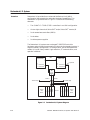
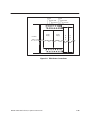
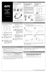
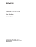
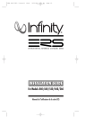
SIMATIC TI505 Redundant I/O System User Manual Order Number: PPX:505–8125–2 Manual Assembly Number: 2586546–0071 Second Edition Copyright 1993 by Siemens Industrial Automation, Inc. All Rights Reserved — Printed in USA Reproduction, transmission or use of this document or contents is not permitted without express consent of Siemens Industrial Automation, Inc. All rights, including rights created by patent grant or registration of a utility model or design, are reserved. Since Siemens Industrial Automation, Inc. does not possess full access to data concerning all of the uses and applications of customer’s products, we do not assume responsibility either for customer product design or for any infringements of patents or rights of others which may result from our assistance. 01/21/92 Technical data is subject to change. We check the contents of every manual for accuracy at the time it is approved for printing; however, there may be undetected errors. Any errors found will be corrected in subsequent editions. Any suggestions for improvement are welcomed. MANUAL PUBLICATION HISTORY SIMATIC TI505 Redundant I/O System User Manual Order Manual Number: PPX:505–8125–2 Refer to this history in all correspondence and/or discussion about this manual. Event Date Description Original Edition Second Edition 10/91 04/93 Original Edition (2591821–0001) Second Edition (2591821–0002) LIST OF EFFECTIVE PAGES Pages Cover/Copyright History/Effective Pages 1-1 — 1-15 Registration Description Second Second Second Second Pages Description SIMATIC TI505 Redundant I/O System User Manual Redundant I/O System . . . . . . . . . . . . . . . . . . . . . . . . . . . . . . . . . . . . . . . . . . . . . . . . . . . . . . . . . . 1-2 Overview . . . . . . . . . . . . . . . . . . . . . . . . . . . . . . . . . . . . . . . . . . . . . . . . . . . . . . . . . . . . . . . . . . Communication Between Units . . . . . . . . . . . . . . . . . . . . . . . . . . . . . . . . . . . . . . . . . . . . . . Planning Redundant I/O Installation . . . . . . . . . . . . . . . . . . . . . . . . . . . . . . . . . . . . . . . . . Determining Signal Losses . . . . . . . . . . . . . . . . . . . . . . . . . . . . . . . . . . . . . . . . . . . . . . . . . . . Using Status Words to Indicate Presence of Redundant I/O . . . . . . . . . . . . . . . . . . . Sending a Role-Swap Command . . . . . . . . . . . . . . . . . . . . . . . . . . . . . . . . . . . . . . . . . . . . 1-2 1–3 1–3 1–4 1–6 1–7 Hardware Components . . . . . . . . . . . . . . . . . . . . . . . . . . . . . . . . . . . . . . . . . . . . . . . . . . . . . . . . . 1–8 Hardware Components . . . . . . . . . . . . . . . . . . . . . . . . . . . . . . . . . . . . . . . . . . . . . . . . . . . . . Software Requirements . . . . . . . . . . . . . . . . . . . . . . . . . . . . . . . . . . . . . . . . . . . . . . . . . . . . . Remote Base Controller . . . . . . . . . . . . . . . . . . . . . . . . . . . . . . . . . . . . . . . . . . . . . . . . . . . . . LED Display . . . . . . . . . . . . . . . . . . . . . . . . . . . . . . . . . . . . . . . . . . . . . . . . . . . . . . . . . . . . . . . . . Setting the RBC Number . . . . . . . . . . . . . . . . . . . . . . . . . . . . . . . . . . . . . . . . . . . . . . . . . . . . Power Supply . . . . . . . . . . . . . . . . . . . . . . . . . . . . . . . . . . . . . . . . . . . . . . . . . . . . . . . . . . . . . . Series 500 I/O Base and Adapter Chassis . . . . . . . . . . . . . . . . . . . . . . . . . . . . . . . . . . . . . Series 505 Dual Media I/O Base . . . . . . . . . . . . . . . . . . . . . . . . . . . . . . . . . . . . . . . . . . . . . . 1–8 1–8 1–9 1–10 1–10 1–11 1–11 1–13 Installing Power Supplies and RBCs . . . . . . . . . . . . . . . . . . . . . . . . . . . . . . . . . . . . . . . . . . . . . . . 1–14 User Supplied Materials . . . . . . . . . . . . . . . . . . . . . . . . . . . . . . . . . . . . . . . . . . . . . . . . . . . . . Safety Guidelines . . . . . . . . . . . . . . . . . . . . . . . . . . . . . . . . . . . . . . . . . . . . . . . . . . . . . . . . . . . Installation and Removal Procedures . . . . . . . . . . . . . . . . . . . . . . . . . . . . . . . . . . . . . . . . SIMATIC TI505 Redundant I/O System User Manual 1–14 1–14 1–14 1-1 Redundant I/O System Overview Redundant I/O provides for an enhanced Hot Backup Unit (HBU) configuration that extends the redundant hardware capabilities. The Redundant I/O system shown in Figure 1-1 consists of the following elements. • Two SIMATIC TI560/TI565 controllers in an HBU configuration • One to eight channels of Series 500 and/or Series 505 remote I/O • Dual remote base controllers (RBCs) • Dual cables • Dual base power supplies The Redundant I/O system uses unchanged TI560/TI565 controller hardware and provides the same major functions as the standard system. It supports memory configuration, I/O configuration, Series 500 operational modes, I/O cycles, Relay Ladder Logic execution, SF communication, and operator interfaces. HBU TI560/TI565 TI560/TI565 Optional R C C R C C Channel 1 Channel 2 Channel 1 Channel 2 Dual Tap and Splitter Trunk A To other taps Trunk B Tap Series 500 Base P P S* S* To other taps Tap R B C R B C and/or P P S* S* R B C R B C Series 505 Base * Power Supply I002741 Figure 1-1 Redundant I/O System Diagram 1-2 SIMATIC TI505 Redundant I/O System User Manual Communication between Units Standard CATV taps and splitters combine I/O channels from the remote channel controllers (RCCs) to form two separate trunks (redundant I/O). Each trunk leads to one of two RBCs located in a chassis that can house two power supplies, although only one power supply is necessary. When the active RCC transmits, the dual tap and splitter arrangement splits the signal three ways: • To the stand-by RCC • To Trunk A • To Trunk B When the active RBC transmits, the dual tap and splitter arrangement splits the transmitted signal from either Trunk A or Trunk B two ways: • To the stand-by RCC • To the active RCC Each redundant RCC, RBC, or power supply can detect internal operating faults. During normal operation, the RCC detects trunk faults and recognizes the appearance or disappearance of redundant RBCs and power supplies. When a fault is detected in the unit designated as active, the corresponding backup unit automatically assumes control with minimal process interruption and without operator intervention. All input, output and SF message transactions occur between the active RCC and the active RBC. The active RCC directs configuration messages to both the active and stand-by RBCs, and the addressed RBC is responsible for acknowledging the message. A “status request” command goes to the active RBC to determine dual power supply status and to the stand-by RBC to determine the condition of the stand-by transmitters. If the stand-by does not respond to this request, the RCC directs the active RBC to command the stand-by to assume a failed state. When communication problems develop between the RCC and the active RBC, the RCC directs a “role swap” command to the stand-by RBC. Planning Redundant I/O Installation The SIMATIC TI560T/TI565T System Manual (PPX:560/565–8105–x) contains detailed instructions for installing remote I/O and for developing a power budget. The SIMATIC TI560/TI565 Hot Backup Installation Manual (PPX:560/565–8103–x) provides details about the additional signal losses with the Hot Backup Unit. Consult these manuals for installing the overall I/O system. NOTE: The x on the manual order number designates the manual edition. SIMATIC TI505 Redundant I/O System User Manual 1-3 Redundant I/O System (continued) Determining Signal Losses The installation of the Redundant I/O system requires dual cables and a dual tap/splitter arrangement as shown in Figure 1-2. In developing the power budget, you must include the dual tap and splitter losses. Table 1-1 lists typical losses obtained when using taps and splitters. See Figure 1-2 for location of the losses. IL To Active TI560/TI565 IL Tap 1 To Stand-by TI560/TI565 Tap 2 TL TL TL TL SL IL – Insertion Loss TL – Tap Loss SL – Splitter Loss Splitter 1 Trunk A SL SL Splitter 2 SL Trunk B Recommended tap values: 7.0 dB (insertion loss of 2.7 dB) I002742 Figure 1-2 Dual Tap-splitter Arrangement for each I/O Channel 1-4 SIMATIC TI505 Redundant I/O System User Manual Table 1-1 Typical Tap and Splitter Losses Type of Loss Amount of Power Loss Tap loss 7.0 dB Tap insertion loss 2.7 dB Splitter loss 3.5 dB Table 1-2 shows calculations for typical dual tap losses. Table 1-2 Dual Tap Losses Dual Tap Loss Total Power Loss Active to stand-by 14.0 dB Active to trunk A 6.2 dB Active to trunk B 10.5 dB Stand-by to trunk A 6.2 dB Stand-by to trunk B 10.5 dB For example: To calculate loss for Active to stand-by, add the two tap losses. To calculate Active to Trunk A loss, add the insertion loss and the splitter loss. To calculate Active to Trunk B loss, add the tap loss and the splitter loss. SIMATIC TI505 Redundant I/O System User Manual 1-5 Redundant I/O System (continued) Using Status Words to Indicate Presence of Redundant I/O CPU software includes additional status words to indicate the presence of Redundant I/O components. Status words 168–175 indicate whether or not dual RBCs are present; status words 176–183 indicate the presence of dual power supplies. Table 1-3 lists the status words and shows the channel/base indicated by each word. If a 1 appears in a bit showing the status of a base containing dual RBCs, check the corresponding bit for that base in status words 2–9 to determine if the other RBC is still functioning. Table 1-3 Status Words Status Words Indicating Dual RBCs Status Words Indicating Dual Power Supplies Word Bit* Base Channel Word Bit** Base Channel 168 16 ↓ 1 0 ↓ 15 1 176 16 ↓ 1 0 ↓ 15 1 169 16 ↓ 1 0 ↓ 15 2 177 16 ↓ 1 0 ↓ 15 2 170 16 ↓ 1 0 ↓ 15 3 178 16 ↓ 1 0 ↓ 15 3 171 16 ↓ 1 0 ↓ 15 4 179 16 ↓ 1 0 ↓ 15 4 172 16 ↓ 1 0 ↓ 15 5 180 16 ↓ 1 0 ↓ 15 5 173 16 ↓ 1 0 ↓ 15 6 181 16 ↓ 1 0 ↓ 15 6 174 16 ↓ 1 0 ↓ 15 7 182 16 ↓ 1 0 ↓ 15 7 175 16 ↓ 1 0 ↓ 15 8 183 16 ↓ 1 0 ↓ 15 8 * Bit=0: Dual RBCs present and good Bit=1: Error condition or single RBC ** Bit=0: Dual power supply present and good Bit=1: Error condition or single power supply MSB 1 LSB 2 3 4 5 6 7 8 9 10 11 12 13 14 15 16 Figure 1-3 TI560/TI565 Bit Order 1-6 SIMATIC TI505 Redundant I/O System User Manual Sending a Role Swap Command The user-commanded role swap feature of the Redundant I/O system allows an orderly transition of the active unit to a stand-by status. The original stand-by unit then assumes the active role. This feature is accessed using a task code formatted as follows: TC = 43FE + LAR + 0310 + RCC + RBC where LAR = two hex digits, F1 for role swaps on bases on channels 0 and 1 F2 for role swaps on bases on channels 2 and 3 F4 for role swaps on bases on channels 4 and 5 F6 for role swaps on bases on channels 6 and 7 RCC = single hex digit corresponding to channel number (0 – 7) RBC = single hex digit corresponding to base number (0 – F) This task code is transmitted either directly to the Redundant I/O system as formatted above, or as the body of a native primitive “01” to a TIWAY Host Adapter. For example, to command base 0 on channel 1 to do a role swap, send either: 43FEF0031010 task code or 0143FEF0031010 TIWAY command To command base 15 on channel 7 to conduct a role swap, send either: 43FEF603107F task code or 0143FEF603107F SIMATIC TI505 Redundant I/O System User Manual TIWAY command 1-7 Hardware Components Hardware Components ! WARNING The remote I/O for the Redundant I/O system consists of a Hot Backup installation, plus the following components for each Series 500 redundant I/O base. • Two PPX:500–2114A Remote Base Controllers (RBCs) • Two power supplies: PPX:500–2151A 110/220 VAC or PPX:500–2153 24 VDC • PPX:500–5864, 8-slot base or PPX:500–5828, 16-slot base • PPX:500–9940 Redundant Controller Adapter Chassis • User-supplied cables, grounding materials, and taps To help avoid potential for personal injury or damage to equipment, do not use PPX:500–2151 power supply or non-dual RBCs with a PPX:500–9940A adapter chassis in a redundant I/O configuration. Do not use the PPX:505–6660 power supply in a redundant I/O configuration. To do so may cause improper operation of your system. Use the following components for a Series 505 redundant I/O base. Software Requirements • Two PPX:505–6850A Remote Base Controllers (RBCs) • Two power supplies: PPX:505–6660A 110/220 VAC or PPX:505–6663 24 VDC • PPX:505–6511, 11-slot base • User-supplied cables, grounding materials, and taps You must have Release 2.1 or greater of RCC, CPU, SFCPU, and HBU software. You can use either the dual RBC or dual power supply in single mode operation with any RCC software releases. Non-dual RBCs can be used with any RCC. NOTE: With earlier software releases, a redundant I/O base with dual RBCs causes the RCC to fail that base. 1-8 SIMATIC TI505 Redundant I/O System User Manual Remote Base Controller Each RBC (Figure 1-4) in the Redundant I/O system is an intelligent interface between an RCC and a remote base. You can locate the dual RBCs up to 15,000 feet from the controller. If both RBCs are installed in the same base, and are operational at power-up, the RBC on the right assumes the active role. Series 500 RBCs MODEL 500–2114A STATUS MODEL 500–5114 Series 505 RBCs STATUS REMOTE BASE CONTROLLER CODES BASE REMOTE BASE CONTROLLER CODES STATUS STATUS BASE BASE BASE BAUD RATE REMOTE BASE CONTROLLER RS232 RS485 REMOTE BASE CONTROLLER RS232 I/O 505–6851 505–6850A COMM PORT I002743 Figure 1-4 Remote Base Controllers SIMATIC TI505 Redundant I/O System User Manual 1-9 Hardware Components (continued) LED Display The LED at the top of each RBC displays a number to indicated RBC status or errors. The messages conveyed by the numbers are shown in Table 1-4. Table 1-4 LED Codes Number Meaning 0 RBC good- configuration ok 1 Self-diagnostics failure 2 Module Mismatch 3 Communications time-out 4 RAM parity error 5 Stand-by unit, not configured 6 Stand-by good, wrong address 7 Communications good, but no I/O configured 8 Watchdog time-out C Stand-by unit, configured NOTE: If an RBC is configured in the controller (LED display 0) and you deleted it from controller memory, the LED display does not change (LED display 7) until a restart or power cycle is performed. To reset an RBC with a 1 displayed, move the base address thumbwheel switch to another address for 0.5 seconds, then return the switch to the correct address. The RBC attempts to come on-line. Setting the RBC Number 1-10 The top thumbwheel switch on the face of each RBC allows you to select the RBC number (0–15) on the RCC channel. RBC numbers must not be duplicated on another base; but the active and stand-by RBCs on the redundant base must have the same number. SIMATIC TI505 Redundant I/O System User Manual Power Supply The Series 500 and 505 Redundant I/O systems each use two power supply modules, and two RBCs installed in the appropriated dual medial base. The following power supplies are available: • PPX:500–2151A and PPX:505–6660A accept 110/220 VAC inputs • PPX:500–2153 and PPX:505–6663 accept 24 VDC inputs All models provide regulated +5 V and –5 V power to the base. All power supplies are normally active during dual media operation with each sharing a portion of the load current. If one power supply fails, the other power supply provides the full load current and the RBC provides a status indication that one supply has failed. Each power supply module provides output overvoltage, overcurrent and undervoltage protection. The indicator labeled DC GOOD is on when the module is producing the correct DC power. The indicator is off when overvoltage, undervoltage, or overcurrent faults are detected. NOTE: To allow replacement of a unit without taking down the entire base, power to each power supply must come from separate sources, and you must provide a means of disconnecting power from each power supply. Series 500 I/O Base and Adapter Chassis To install the dual RBCs and power supplies, use either the PPX:500–5864, 8-slot base or the PPX:500–5825 16-slot base with the PPX:500–9940 Redundant Controller Adapter Chassis. The adapter chassis attaches to the right side of the I/O base and provides slots for the two power supplies and the two RBCs. In planning the installation of the I/O bases for the Redundant I/O system, follow the guidelines in the manual that comes with the bases. To mount the PPX:500–9940 Adapter Chassis, see Figure 1-5 for template dimensions, and follow these steps. 1. When preparing the mounting panel, position the base and adapter for proper contact of the connectors. 2. Partially insert the two top screws in the panel. 3. Fit the screws into the holes in the adapter base (see Figure 1-5). Slide the assembly down and to the left until the screws support the adapter chassis and the base connectors are fully seated. 4. Attach the lower portion of the assembly to the panel with two #10 screws. 5. Tighten all screws. SIMATIC TI505 Redundant I/O System User Manual 1-11 Hardware Components (continued) 8.00 in (20.34 cm) 3.29 in (8.37 cm) 2 pl 0.75 in (1.90 cm) 4 pl + + + + + + 0.25 in (0.64 cm) 2 pl 14.20 in (36.00 cm) 0.21 in (0.53 cm) 4 pl + + + + 1.35 in (3.44 cm) I002744 Figure 1-5 1-12 Dimensions for the PPX:500–9940 Adapter Chassis SIMATIC TI505 Redundant I/O System User Manual Series 505 Dual Media I/O Base The PPX:505–6511 dual media base has slots for two power supplies and two RBCs, with 11 I/O slots. (The base housing is physically the same size as the PPX:505–6516 16-slot I/O base.) Refer to Figure 1-6 for the housing dimensions. 0.64 in (16.26) cm 17.70 in (448.58 cm) 0.64 in (16.26 cm) 8.97 in (227.81 cm) 10.47 in (265.94 cm) 17.70 in (448.58 cm) 1.47 in (37.31 cm) I002745 Figure 1-6 Dimensions for the PPX:505–6516 (16-slot Base) The power supplies must be mounted in the first two slots on the left of the base. The RBCs are mounted in the slots to the right of the power supplies. Figure 1-7 shows the correct mounting positions for the power supplies and RBCs in the Series 505 dual media I/O base. 11 I/O slots P / S P / S R B C R B C I002746 Figure 1-7 TI505 Dual Media I/O Base SIMATIC TI505 Redundant I/O System User Manual 1-13 Installing Power Supplies and RBCs User Supplied Materials To install the Redundant I/O system, you need the following additional materials: • CATV grounding blocks or bulkhead coaxial connectors to install at each RCC and RBC to shunt noise on the coaxial cable shield to ground • Semi-rigid coaxial cable (two sizes) to use for trunk line(s) and for drop lines • CATV taps to insert in the trunk distribution cable to provide drops from the active and stand-by controllers to the RBCs • Taps and splitters to distribute the signal from the active RBC (either Trunk A or B) to the stand-by RCC and the active RCC • Semi-rigid coaxial cable fittings to connect trunk distribution cable to tap housing • F-type connectors to connect drop cable to tap housing • Terminators to install on all unused terminals on a multi-drop tap ! WARNING To help avoid potential damage to equipment and/or personal injury, install redundant I/O components in a non-hazardous location. For example, ensure that flammable gases are not present before inserting or removing RBCs or power supplies. ! CAUTION In order to prevent disruption of the I/O channel, disconnect the coaxial cable before removing or installing an RBC. Installation and Removal Procedures 1-14 To install the Redundant I/O components: 1. Plug an RBC into each of the two designated slots and tighten the top and bottom screws on each unit. The RBC in the right slot assumes the active role when the base is powered up. 2. Connect a coaxial cable to each RBC. 3. Plug the power supplies into the designated slots. Be certain the module is fully seated. 4. After the power supply is inserted, attach the power and ground wires as shown in Figure 1-8. SIMATIC TI505 Redundant I/O System User Manual AC Hot Chassis GND AC Hot Chassis GND AC Common Power Supply I/O Base Power Supply AC Common R R B B C C I002747 Figure 1-8 TI500 Power Connections SIMATIC TI505 Redundant I/O System User Manual 1-15 Customer Registration We would like to know what you think about our user manuals so that we can serve you better. How would you rate the quality of our manuals? Excellent Good Fair Poor Accuracy Organization Clarity Completeness Overall design Size Index Would you be interested in giving us more detailed comments about our manuals? Yes! Please send me a questionnaire. No. Thanks anyway. Your Name: Title: Telephone Number: ( ) Company Name: Company Address: Manual Name: SIMATIC TI505 Redundant I/O System User Manual Manual Assembly Number: 2586546–0071 Order Number: PPX:505–8125–2 Edition: Date: Second 04/93 FOLD NO POSTAGE NECESSARY IF MAILED IN THE UNITED STATES BUSINESS REPLY MAIL FIRST CLASS PERMIT NO.3 JOHNSON CITY, TN POSTAGE WILL BE PAID BY ADDRESSEE SIEMENS INDUSTRIAL AUTOMATION, INC. 3000 BILL GARLAND RD. P.O. BOX 1255 JOHNSON CITY TN 37605–1255 ATTN: Technical Communications M/S 3519 FOLD SIMATIC is a registered trademark of Siemens AG. Series 500, Series 505 and TIWAY are trademarks of Siemens Industrial Automation, Inc. TI560, TI560T, TI565 and TI565T are trademarks of Texas Instruments Incorporated.