1
IDEAL INDUSTRIES, INC.
TECHNICAL MANUAL
MODEL: 61-360
The Service Information provides the following information:
• Precautions and safety information
• Specifications
• Performance test procedure
• Calibration and calibration adjustment procedure
• Basic maintenance (replacing the battery and fuses)
Form number: TM61360
Revision: 2. Date: Oct 2002
Form number TM61360
Rev 2 October 2002
TABLE OF CONTENTS
Page
Title
Introduction
1
Precautions and Safety Information
1
Safety Information
1
Specifications
2
General Specification
2
Voltage Specifications
2
Current Specifications
2
Resistance Specifications
2
Diode / Continuity Specifications
2
Performance Verification
3
Table 1 Verification 61-360
3
Calibration
4
Replacing the Battery
5
Replacing Fuses
5
Form number TM61360
Rev 2 October 2002
Page 1
Introduction
Warning
To avoid shock or injury, do not perform the verification tests or calibration
procedures described in this manual unless you are qualified to do so.
The information provided in this document is for the use of qualified personnel only.
Caution
The 61-360 contains parts that can be damaged by static discharge.
Follow the standard practices for handling static sensitive devices.
For additional information about IDEAL INDUSTRIES, INC. and its products,
and services, visit IDEAL INDUSTRIES, INC. web site at:
www.idealindustries.com
SAFETY
Review the following safety precautions to avoid injury and prevent damage to this product or any
products connected to it. To avoid potential hazards, use the product only as specified.
It is recommended that you read through the Operation or User manual before starting. Not all Caution,
Warning, or Danger precautions are listed in this manual.
CAUTION.
These statements identify conditions or practices that could result in damage to the equipment or other
property.
WARNING.
These statements identify conditions or practices that could result in personal injury or loss of life.
Specific precautions
Use proper Fuse. To avoid fire hazard, use only the fuse type and rating specified for this product.
Do not operate without covers. To avoid personal injury, do not apply any voltage or current to the
product without the covers in place.
Electric overload. Never apply a voltage to a connector on the product that is outside the range specified
for that connector.
Avoid electric shock. To avoid injury or loss of life, do not connect or disconnect probes or test leads
while they are connected to a voltage source.
Do not operate in wet/damp conditions. To avoid electric shock, do not operate this product in wet or
damp conditions.
Form number TM61360
Rev 2 October 2002
Page 2
General specifications
Characteristics
Display
Display Count
Overrange Indication
Sampling Rate
Operating Environment:
Relative Humidity
Temperature Coefficient
Storage Environment:
Power source:
Battery Live:
Low Battery Indicator:
Auto Power Off mode
A protection Fuse
Dimensions
Weight:
Safety
Description
3 ½ Digit LCD display
2000 count, maximum reading 1999
“OL” displayed
3 time/second
0°C to 50°C (32°F to 122°F) 70%RH
0.05X x (accuracy) per °F (32°F to 65°F, 85°F to 122°F
-20°C to 60°C (0°F to 140°F) at <70 relative humidity
9V Battery (NEDA 1604)
300 hours typical (alkaline)
symbol indicates low battery voltage
Approximately 25 minutes
0.5A/250V fast acting fuse Type LA-3895
10A/600V fast acting fuse, Type LA-3897
5.75” H X 2.75” W X 1.5” D {without holster}
Approximately 18.0 oz. including battery
UL1244, and Design to comply with IEC 1010-1 Cat III
RANGES and ACCURACY SPECIFICATION
61-360
Function Setting
Ranges
200.0mV/2000mV 20.00V
200.0V/ 600V
AC Voltage
50Hz to 500Hz
DC Voltage
200.0mV/2000mV/20.00V/200.0V/600V
200µA/2.00mA/20.00mA/ 10A,
AC Current
50Hz to 500Hz
DC Current
Accuracy
1.0% ± 4 digits
1.5% ± 4 digits
0.5% ± 1digit
1.5% ± 4 digits
200µA/2.00mA/20.00mA/ 10A,
1.0% ± 4 digits
1.0% ± 4 digits
200.0Ω/2.000K/20.00K/200.0K
Resistance
2.0% ± 4 digits
2.000MΩ/20.00MΩ
Not Specified
Continuity
beep < 100Ω
3V DC max
Diode Check
1.5% ± 1 digit
AC Converter:
Average responding, RMS Calibrated to Sine Wave
Overload Protection:
AC and DC Volts: 200mV range, 500VDC or 350V rms for no more that 15
sec
2V to 600V range, 600V DC or AC rms
Resistance, Diode, Continuity: 500V DC or AC rms
mA input: 250V DC/AC rms
Amps input: 600V DC/AC rms on insulated conductors or 250V DC/AC rms
on
un-insulated conductors
Form number TM61360
Rev 2 October 2002
Page 3
PERFORMANCE VERIFICATIONS
Perform the following analysis, if the meter conforms to the limits listed in Table 1 the meter is functioning
correctly. If the meter does not conform to any of the listed limits the calibration procedure must be
performed.
Performance Verification Preparation
1. Turn on the calibrator, allow calibrator to warm up. Temperature stabilization
should be reached after 30 minutes.
2. Remove battery cover and using a calibrated meter to ensure the battery measures a minimum of 7.5V
DC. If the battery measures under 7.5V DC, replace the battery before beginning the performance test.
3. Input the values listed in Table 1 for the Standard 61-360
Table 1 Performance Verification
Function Setting /Range
ACV 200m
ACV 200m
ACV 2000m
ACV 2000m
ACV 20
ACV 20
ACV 200
ACV 200
ACV 600
ACV 600
DCV 200mV
DCV 2000mV
DCV 20V
DCV 200
DCV 600
A DC 200µA
A DC 20mA
A DC 200mA
A DC 10
A AC 200µA
A AC 200µA
A AC 20mA
A AC 20mA
A AC 200mA
A AC 200mA
A AC 10A
A AC 10A
Ω 200
Ω 2K
Ω 20K
Ω 200K
Ω 2M
Ω 20M
Diode Test
Continuity Test
Form number TM61360
Input
190mV AC@ 50Hz
190mV AC@ 500Hz
1900mV @ 50Hz
1900mV @ 500Hz
19.00V AC @ 50Hz
19.00V AC @ 500Hz
190V AC @ 50Hz
109V AC @ 500Hz
500V AC @ 50Hz
500V AC@ 60Hz
190mV DC
1900mV DC
19.00V DC
190.0V DC
500V DC
100µA
10mA
100mA
9.00 DCA
100µA @ 50Hz
100µA @ 500Hz
10mA @ 50Hz
10mA @ 500Hz
100mA @ 50Hz
100mA @500Hz
9A @ 50Hz
9A @ 500Hz
100.0
1.000K
10.00K
100.0K
1.000M
10.00M
500mV
100Ω
Rev 2 October 2002
Low Limit
187.7
187.7
1880
1880
18.77
18.77
186.7
186.7
488
488
188.9
1890
18.89
188.9
496
98.6
9.86
98.6
8.79
98.1
98.1
9.81
9.81
98.1
98.1
8.77
8.77
98.6
.986
9.86
98.6
.986
9.78
492
Beep off
High Limit
192.3
192.3
1919
1919
19.23
19.23
193.2
193.2
511
511
191.1
1909
19.11
191.1
504
101.4
10.14
101.4
9.21
101.9
101.9
10.19
10.19
101.9
101.9
9.22
9.22
101.4
1.014
10.14
101.4
1.014
10.22
509
Continuity Test
Beep on
20Ω
Page 4
CALIBRATION
Calibration Preparation
Required Equipment
The class of calibrator or equipment should have an accuracy that exceeds, by an expectable ratio the
accuracy of this instrument.
1.
Turn on the calibrator, allow calibrator to warm up. Temperature stabilization
should be reached after 30 minutes.
2. Disconnect the test leads and turn the range switch to “OFF”.
3. Remove the screw holding the bottom case cover, just above the battery cover.
4 The case bottom is secured to the case top by two internal snaps (at the LCD end).
lift up on the battery end until the case un-snaps.
5 Using a calibrated meter ensure the battery measures a minimum of 7.5V DC.
If the battery measures under 7.5V DC, replace the battery.
Calibration Procedure
It is recommended that all IDEAL meters undergo the following calibration procedure on
an annual basis.
61-360 Calibration Procedure
Calibration
1. Set the Function/Range Switch to the “200mV DC” position.
2. Set the output of the DC calibrator for 190.0mV and connect it to the “V-Ohm” and “COM”
input terminals.
3. Adjust VR1 (VR 200 ohm) until the display reads 190.0mV +/- 1 digit.
Note: This is the only adjustment required for the 61-360. Calibration is complete.
Form number TM61360
Rev 2 October 2002
Page 5
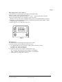
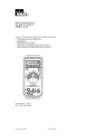
Battery Replacement (refer to Figure 1)
1. Disconnect the test leads from any circuit under test and turn off meter.
2.Remove the three screws for the back case cover.
3. Remove battery from compartment noting the “+” and “- “ position of the battery terminals.
4. Remove the plastic battery sleeve and place it on the new battery
(Damage can occur to the circuit if the plastic battery sleeve is not replaced with the new battery)
5. Install new 9V battery (NEDA #1604) into the compartment and assure proper polarity of battery.
An alkaline type is recommended.
6. Install bottom case cover and secure with screws.
Figure 1
Replacing Fuses
1. Disconnect the test leads and turn the range switch to “OFF”.
2. Remove the three screws holding the bottom case cover
3 Use a digital multimeter in low resistance {ohms} mode to check the two fuses
mA input, 0.5A / 250V fast acting fuse.
Amp input, 10A / 600V fast acting fuse
4. Replace the defective fuse with the recommended fuse type.
mA: 0.5A/250V fast acting fuse Type LA-3895 is recommended.
Amp: 10A/600V fast acting fuse, Type LA-3897 is recommended
5. Install bottom cover and secure with screws.
Form number TM61360
Rev 2 October 2002