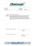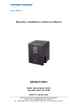
1
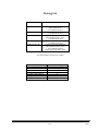
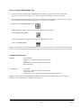
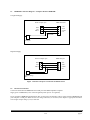
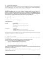
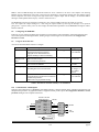
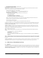
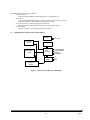
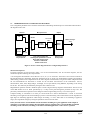
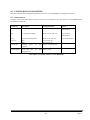
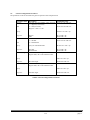
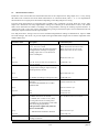
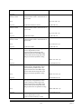
HMR3000
Digital Compass Module
User’s Guide
900240 Rev. B
3/01
Packing List
Part Number
Items included
HMR3000-D00-232
HMR3000 RS 232 Circuit Card
Demo Software and
Users Manual CD-Rom
HMR3000 RS 485 Circuit Card,
Users Manual CD Rom
Housed Compass Module RS232
Demo Software Disk 1 and 2*
Users Manual CD Rom
Housed Compass Module RS485
Users Manual CD Rom
Housed Compass Module RS232
Demo Software Disk 1 and 2*
User’s Manual CD Rom
Power supply and interface cable
HMR3000-D00-485
HMR3000-D21-232
HMR3000-D21-485
HMR3000 Demo Kit
*PC Demo Software Version 2.01 or higher
Parameter or Condition
Baud Rate
Operation Mode
Output Sentences
Default Setting
19200
Run
None
TC1 (filter 1 time constant)
Heading filter L value
Heading filter S value
4
0
0
900240 Rev. B
3/01
page i
How to Set up HMR3000 Demo Unit
1)
Connect the interface cable between the HMR3000 and COM port of a PC. Select the line voltage input
(110/220 V), turn the voltage selector to 9 V dc mark, and plug in the adapter to an electrical outlet.
2)
Install PC Demo Interface software on the PC by running Setup.exe from CD Rom. In Windows 95 or NT click
start, then Run and browse CD Rom to find Setup.exe. (Version 2.01 or higher)
3)
Double click on PC Demo Interface icon.
Select the correct COM port and 19200 baud rate (COM port is usually COM1).
Click the musical note button
Go to Serial Output tab and change the message rate on HPR sentence to 825.
Click on the display button
Note: You should have received PC Demo Interface Ver. 2.01 or higher. If you have an older version please update to
the latest version. Please call Honeywell customer services at 612-954-2888 if you need this newer version of software
Computer Requirements
Minimum:
PC 486/33MHz
Windows 3.1, Windows 95 or NT Operating System
VGA
2 Mb disk space (more for log file and captured data)
RS-232 serial port
Recommended:
P5/120MHz
Windows 3.1, Windows 95 or NT Operating System
SVGA 1024 x 768
Microsoft Excel (5.0 or greater) for capture and export of data (if desired)
Note: The Graphical output of the HMR3000 on PC Demo software may become sluggish if the PC has slow graphic
capability or if other applications are running in the background.
900240 Rev. B
3/01
page ii
Table of Contents
1.0
INTRODUCTION.............................................................................................1
2.0
GETTING TO KNOW HMR3000 PRODUCT....................................................1
2.1
2.2
2.3
2.4
2.5
2.6
2.7
2.8
2.9
2.10
2.11
2.12
3.0
3.1
3.2
3.3
3.4
3.5
3.6
3.7
3.8
3.9
3.10
3.11
3.12
IDENTIFYING THE PRODUCT ............................................................................................1
SETTING UP ...................................................................................................................1
HMR3000 CONNECTION DIAGRAM – C OMPUTER RS232 TO HMR3000 ............................2
ELECTRICAL CONNECTIONS ...........................................................................................2
COMMUNICATION -RS232 OPTION.................................................................................3
INSTALL PC D EMO INTERFACE .......................................................................................3
GETTING DATA OUT OF HMR3000 ..................................................................................3
CONFIGURING HMR3000 ...............................................................................................4
USING PC DEMO INTERFACE ..........................................................................................4
COMMUNICATION - RS485 OPTION................................................................................4
INSTALLATION ..............................................................................................................5
CALIBRATION................................................................................................................5
OPERATION OF HMR3000 IN DETAIL ..........................................................6
GENERAL ...................................................................................................................6
HMR3000 ELECTRICAL BLOCK DIAGRAM..............................................................7
HMR3000 PROCESS CONTROL BLOCK DIAGRAM..................................................8
MEASUREMENT SEQUENCE ............................................................................................8
INTERFACE P IN DESCRIPTIONS .......................................................................................8
COMMUNICATION ..........................................................................................................9
INPUT ...........................................................................................................................9
OUTPUT ......................................................................................................................10
QUERY FOR NMEA SENTENCES ...................................................................................10
FORMAT OF NMEA SENTENCES OUTPUT ......................................................................10
CHECKSUM FILED ........................................................................................................13
WARNING AND ALARM SETTINGS.................................................................................13
4.0
CONFIGURATION PARAMETERS ...............................................................14
4.2
4.3
4.4
GENERAL CONFIGURATION PARAMETERS .....................................................................15
MEASUREMENT P ARAMETERS ......................................................................................16
SERIAL I/O ..................................................................................................................19
5.0
DESCRIPTION OF HARDWARE INTERRUPT PINS.....................................21
6.0
ALGORITHM FOR THE NON-LINEAR HEADING FILTER..........................21
7.0
PHYSICAL DIMENSIONS............................................................................................................. 22
900240 Rev. B
3/01
page iii
1.0
INTRODUCTION
Thank you for purchasing Honeywell’s HMR3000 Digital Compass Module. The HMR3000 uses Honeywell magnetic
sensors with proven MR technology and a two-axis tilt sensor to bring you the heading information. This electronically
gimbaled compass gives accurate heading even when the compass is tilted up to 40 degrees. The HMR3000 is reliable
and rugged since it does not contain any moving components and uses all surface mountable components. This low
power, small device is housed in a non-magnetic metallic enclosure that can be easily installed on any platform.
The HMR3000 is easy to use and extremely versatile. It allows the user to configure compass output to include any
combination of six NMEA standard messages and to change measurement parameters for the magnetometer to suit the
application. The sophisticated auto compass calibration routines will correct for the magnetic effects of the platform.
Wide dynamic range of the magnetometer (±1 G or 100 µT) allows the HMR3000 to be useful in applications with large
local magnetic fields.
2.0
GETTING TO KNOW THE HMR3000 PRODUCT
2.1
Identifying the product
HMR3000 Compass module comes in three different options:
(1) Circuit board with RS 232 or RS485 electrical interface
(2) Housed Compass Module with RS232 or RS485 electrical interface
(3) Demonstration Kit (RS232 only)
The electrical interface of the compass module is clearly marked on the circuit board in option (1) and on the product
label in option (2). Option (3) only comes with RS232 electrical interface.
2.2
Setting up
Interface and power cables—Interface and power supply should be included in the Demonstration Kit (see Electrical
Connections in Section 2.4).
For other HMR3000 product options, a cable having a standard 9-pin D shell female connector should be wired
according to the pin-out defined below. Power should only be connected to either pin 9 or pin 8. It is sufficient to
connect the pins listed in Table 1 for most applications. However, pins 1, 4, 6 and 7 serve specific purposes in the
operation of HMR3000 and should be kept open (high logic state) in normal operation (see Table 2 for complete pin out
description). See Figure 1 for suggested cabling diagram for connection between HMR3000 and COM port of a
computer (IBM).
Name
In/Out
Pin
Description
TxD / A
Out
2
RS-232 transmit out / RS-485 transmit-receive signal
RxD / B
In
3
RS-232 receive in / RS-485 transmit-receive return
GND
In
5
Power and signal common
6-15V
In
9
Unregulated power input
5V
In
8
Regulated power input
Table 1. Pin assignment for typical operation of HMR3000 (See Table 2 for complete description)
Caution: Do NOT exceed +5.5V at regulated power input (pin 8). Higher voltages will damage components.
900240 Rev. B
3/01
page 1
2.3
HMR3000 Connection Diagram—Computer RS232 to HMR3000
Unregulated Supply
R-232 computer pins
HMR 3000 PINS
2 TX
3 RX
5 GND
9 V+
RX 2
TX 3
GND 5
6-15 Vdc
ac adapter
Regulated Supply
RS-232 computer pins
HMR 3000 pins
2 TX
3 RX
RX 2
TX 3
GND 5
5 GND
8 V+
5 Vdc
Regulated voltage
source
Figure 1. Interface and power connections for RS232 devices
2.4
Electrical Connections
Connect the cable between HMR3000 and a COM port of the IBM compatible computer.
Supply power to HMR3000 (6-15V at the unregulated power input or 5V regulated).
If you purchased a HMR3000 Demonstration Kit, use the power and interface cable to connect between HMR3000 and
your computer’s COM port. Make sure the line voltage selection (110 or 220V) in the adapter is appropriate and that 6
Vdc or higher output voltage (<15V) is selected.
900240 Rev. B
3/01
page 2
2.5
Communication—RS232 Option
The HMR3000 communicates with an external host via RS232 or RS485 electrical standard through simple ASCII
character command strings. A host computer can direct operation of HMR300 with these commands. With the RS232
option a user friendly graphical interface is provided to direct operation of the compass.
RS232 Option
The Compass Module is supplied with PC Demo Interface, a software program that allows the user to configure
HMR3000 with the RS232 option. This program is for IBM PC compatible machines running MS Windows 3.11,
Windows 95 or Windows 97. PC Demo Interface allows the user to communicate between the HMR3000 and the PC.
This is used to configure the HMR3000, receive compass outputs, and to log and capture compass messages. PC Demo
also demonstrates the input/output options available, and is a great tool to learn about HMR3000.
2.6
Install PC Demo Interface
Enclosed is a CD Rom containing PC demo. Software is included.
Run Setup.exe from CD Rom.
The installation software will guide through the process.
Computer Requirements
Minimum:
PC 486/33 MHz
Windows 3.1, Windows 95 or NT Operating System
VGA
2 Mb disk space (more for log file and captured data)
RS-232 serial port
Recommended:
P5/120 MHz
Windows 3.1, Windows 95 or NT Operating System
SVGA 1024 x 768
Microsoft Excel (5.0 or greater) for capture and export of data (if desired)
Note: The Graphical output of the HMR3000 on PC Demo software may become sluggish if the PC has slow graphic
capability or if other applications are running in the background.
2.7
Getting data from HMR3000
Once the power and interface cables are connected and the software installed in your computer, begin to acquire compass
data from HMR3000.
Launch PC Demo Interface by double clicking the program icon in PC Demo Interface window.
Select the appropriate COM port and choose 19200 as the baud rate (factory setting).
Message box, identifying the Firmware Version, should appear.
This message indicates a successful installation and interface connection.
Activate Tune Parameters in the PC Demo Interface (from the Parameters menu or use the Tune button).
The compass is in RUN (Continuous) mode with NO messages coming out.
(Message rates for all the output sentences are set to 0 at the factory).
Set the message rate of HPR sentence to 825 (Tune Page \ Serial Output). Now the compass should output heading, pitch
and roll data at 825 sentences/min rate.
Activate Display \ View Interface, or Display \ Monitor NMEA Sentences to see the output.
Diagnostics \ View Log is another option to inspect compass data. Make sure the Log all messages (logging page in Diagnostics
\ Options menu) option is activated.
900240 Rev. B
3/01
page 3
Note: A non-zero HPR message rate should be chosen for View \ Interface to be active. The compass rose showing
Heading ant Tilt information will require a fast processor (Pentium) to respond fast enough with the compass output.
Slower computers will result in large time lags between the compass output and the display. All selected NMEA
messages will be updated in the Display \ Monitor NMEA Sentences
The HMR3000 output can be changed to include all or any of the six NMEA sentences each with its own rate.
User can capture the output messages to a file using the Capture Mode by selecting the message to be captured.
[Diagnostics \ Options menu]. User can also change the measurement parameters of the HMR3000 through PC Demo
Interface software.
2.8
Configuring the HMR3000
Following is a list of basic parameters that would be accessed routinely and at installation. Advanced parameters that
control the operation of the magnetometer, heading output, and warning levels are described in the Configuration
Parameters section
2.9
Using PC Demo Interface
Activate the Tune Parameters button to configure.
Function
Declination
Output
Messages and
Rate
Data Filter
Heading Output
Deviation
Parameter /Description
Declination
Angle between magnetic north and
geographic north. Add declination to
magnetic heading to obtain True heading
HDG, HDT, XDR, HPR, RCD, CCD
NMEA sentence outputs
Rates in sentences per minute
TC1
Time constant for IIR filter
L and S
Smoothing factors for non linear filter
Located under
General page
Range
± 0-180 deg
± 0- 3200 mils
Serial Output page
None or All
0-1200 /min
Deviation
The angle between compass forward direction
and that of the platform.
Add deviation to get platform heading
General page
0-255
1=72 ms
0<S<1
L= integer >1
L=0 disable
L<256
± 0-180 deg
± 0- 3200 mils
Table 2. Parameters attached routinely or at installation
2.10 Communication—RS485 Option
Operation and configuration of a HMR3000 with RS485 interface is directed through direct command input from the host
computer/microprocessor. No graphical interface is supplied with this product option. See Configuration Parameters section
for details and Figure 2 for computer connections.
RS-232
TD
RD
GD
RS-232 to RS-485
B & B Electronics
#485TBLED
SD Con trol
Shield 1
Echo Off
TD(A) 2
TD(B) 3
2 RD
RD(A) 4
3 TD
RD(B) 5
7 GD
GND 6
+12V 7
VAC
RS -485
+12VDC
900240 Rev. B
3/01
(B)
(A)
2
3
RS -485
Gnd
Pwr
5
9
Gnd
+12 VDC
DB9 socket
connector
page 4
Figure 2. RS485 to Computer Connection
The HMR3000 Compass module’s RS-485 interface is half duplex, i.e. transmit and receive circuits share the same physical
pair of wires. The HMR3000 must disable its transmitter to allow characters to be received from a host system. If the unit is
operating in Run mode, i.e. generating repetitive output, then the Run / Stop pin (pin # 6) should be forced low before the host
attempts to transmit a command. See details in Description of hardware interrupt section.
2.11 Installation
To get optimum performance when installing HMR3000, follow the guidelines listed below for your vehicle or platform.
Location—Install the HMR3000 as far as possible from any source generating a magnetic field and far from ferrous
metal objects. Honeywell magnetic sensors used in HMR3000 have a large field range of ± 1G (± 100 µT), compared to
0.65 G (65 µT); the maximum of earth’s total magnetic field, and therefore would not saturate in most platforms.
Calibration and compensation routines in the compass can effectively compensate for static magnetic fields
superimposed on the earth’s field components, which are used for heading calculations. However, compasses can not
compensate for the effects of varying fields produced by dc and ac currents.
Level—Since the HMR3000 is electronically gimbaled it is not necessary to mount the compass leveled. However, to get
the maximum possible tilt range, the compass should be mounted level when the vehicle or platform is in normal
operation.
Orientation—Forward direction of the compass can be oriented at any angle from that of the platform. Use Deviation
parameter to convert the compasses magnetic heading to true or magnetic heading of the vehicle/platform
2.12 Calibration
All magnetic compasses have to be calibrated in order to compensate for magnetic fields other than the earth’s field
components to get accurate heading. These additional magnetic fields are generated by the host and therefore depend on
the compass mounting location. By performing a simple procedure, the HMR3000 can compensate for steady, static
magnetic fields known as hard iron fields. Field components found after a calibration are only valid for the particular
orientation and location of the compass. A re-calibration is necessary after a relocation of the compass or if the platform
has changed its magnetic character.
Compass calibration is performed by following a calibration procedure specified by the manufacturer. During this
procedure the compass collects data required for the compensation algorithms. The goal of the calibration procedure is to
sample the magnetic field components for many possible orientations of the host system. Rotating the host system
through 360 degrees or driving in a circle (in the case of a vehicle) will enable the compass to sample its magnetic
environment. The HMR3000 can be calibrated by either using the built in calibration method or by using the PC Demo
Interface software program. The calibration procedure for both these methods is the same.
Built-in Calibration Method—This method uses an iterative procedure to calculate the hard iron offsets. In most
situations 275 iterations would produce good results. The calibration procedure has to continue until this iteration count
is reached.
To put the HMR3000 into calibration mode (issue #F33.4=0*51<CR><lf>):
Slowly rotate the host system through a full circle in a gentle motion while changing roll and pitch as much as the
host will allow. Generally this procedure will take over two minutes.
Check the iteration count by issuing #I26C?*31<CR><lf>. HMR3000 will reply with a #nnnn*hh<CR><lf>
message, where nnnn is the value of the iteration count.
If this value is less than 275 continue with the calibration procedure until that number reaches 275.
At the end of this procedure issue a command to save the results in the EEPROM (#F2FE.2=1*67<CR><lf>)
Put the unit back into Operate mode (issue #F33.4=1*50<CR><lf>)
900240 Rev. B
3/01
page 5
This method works when the hard iron field is small.
PC Demo Interface Software Method
3D Calibration—This method is recommended when the hard iron field is large. The PC demo interface will collect
magnetic vector information and analyze to find the hard iron offsets.
Launch PC Demo Interface (Ver. 2.02 or higher)
In PC Demo, go to Diagnostics menu and to Perform 3D Calibration menu
In Hard Iron page, activate Read Data
You should see the Total Valid Readings (# of data points collected) go up.
If not check the following
First quit the Cal page
Go to Diagnostics \ Options \ Calibration
Select Real Time Data from Unit by clicking that option
Slowly rotate the platform through a full circle in a gentle motion while changing roll and pitch as much as the
platform will allow. Generally this procedure will take over two minutes.
At the end of this procedure hit Stop.
Once the computation is complete hit Apply to put the Hard Iron offsets into the unit.
If sufficient tilt change were not encountered during the calibration procedure, then the calculated Zoffset value may not
be reliable. In such case the Z offset will appear in red, and the corresponding check box empty. User has the option to
accept this value by checking the box.
Z Reference Method—In applications which changing the tilt of the host is not possible, an approximate value of the
Zoffset can be found by using the Z Reference Method. This method directly compares the Z component of the earth’s
magnetic field in an undisturbed location to that of the host.
This procedure involves two steps:
Step 1. Collect Z reference value near the calibration site, away from large metal objects that will distort the earth’s
field by:
Activating Diagnostics \ Capture/Clear Z Reference
Hit Read Data
Hold the compass approximately level
Hit Stop after capturing 10-20 readings and hit ‘Apply’ to save the new Z Reference value in the EEPROM of
HMR3000.
Step 2. Install the compass on the host and follow the normal 3D Calibration described above. Mag Z offset will be computed
from the Z Reference method as well as the normal method, and the most appropriate value is indicated by a cross mark against
the value.
Goodness of Calibration—At the end of each calibration, PC Demo calculates and reports a variation number; the lower
the number the better the calibration. The compass should be relocated if the variation number is greater than 40.
3.0
OPERATION OF THE HMR3000 IN DETAIL
3.1
GENERAL
The HMR3000 consists of three magnetoresistive magnetic sensors and a liquid filled two-axis tilt sensor to produce tilt
compensated heading data. A microprocessor controls the measurement sequence of the sensors, and all the parameters
that control the operation are stored in an EEPROM. The output sentences of the HMR3000 conform to the NMEA 0813
standard for Marine communication.
900240 Rev. B
3/01
page 6
The HMR3000 has four operational modes
Continuous Mode
Output unsolicited NMEA standard message(s) at a configurable rate
Strobe Mode
Active Strobe Mode- Measurement is continuous and message output on request
Passive Strobe Mode- Measurement and output upon request
Sleep Mode (requires an interrupt signal at the connector)
Both measurement and output are suspended with serial inputs ignored
Calibrate Mode
Enter the compass in to user Hard Iron calibration mode
3.2
HMR3000 ELECTRICAL BLOCK DIAGRAM
Regulator
Tilt Sensor
2-Axis
Magnetometers
3-Axis
5V
6–15 Vdc
EEPRROM
Micro
processor
RS232
RS485
Continuous/Reset
Operate/Calibrate
Run/Stop
Ready/Sleep
Tx
Rx
Gnd
Analog Drive
Circuits
Figure 3. Electrical block diagram of HMR3000
900240 Rev. B
3/01
page 7
3.3
HMR3000 PROCESS CONTROL BLOCK DIAGRAM
User configurable parameters that control the measurement and heading calculation process is denoted at the bottom of
the diagram in italic font.
Sensors
Tilt
Microprocessor
Output
A, B
IIR Filter
Non Linear
Filter
Heading
Calculation
6 NMEA Messages
ASCII
RS232
RS485
L and S
Magnetometer
TC1
X, Y, Z
Set/Reset Interval
Mag Sample Rate
Filter time constant TC1
Heading filter parameters L and S
Alarm and warning levels
Hard iron coefficients
Strobe mode count
Message Type
Message Rate
Figure 4. Process control diagram and user configurable parameters
Measurement Sequence
In normal operation, the microprocessor takes a set of seven measurements, four tilt and three magnetic, that are
combined to produce heading, roll, and pitch data.
A set of magnetic measurements can be taken at 110, 55, 27.5, or 13.75 Hz rate. Tilt sensor is driven with a constant 55
Hz pulse. Raw data are normalized, linearized, and filtered at the 13.75 Hz rate. Normalization includes gain matching,
offset nulling, and hard-iron compensation for the three magnetic measurements; and gain and offset compensation for
tilt. Tilt measurements are linearized to account for the non-linear characteristics of the inclinometer. All five
measurements, TiltX, TiltY, MagX, MagY, and MagZ, are low-pass filtered, using IIR filter, depending on the setting
for the TC1. This filter may be disabled by setting the time constant to zero.
Magnetometer operation includes a Set/Reset pulse to achieve high sensitivity magnetic measurements. The active area
of the MR element is Set or Reset periodically by a 3 amp current pulse through the patented on chip coils. The
periodicity of this Set Reset operation can be changed to achieve high heading accuracy or to conserve power.
Compass heading is calculated 13.75 times per second from the 5 filtered measurements. A form of non-linear
smoothing can be applied to the current heading to produce a smooth heading. The transfer function of the algorithm is a
high degree of smoothing applied for small changes in heading, i.e. noise, while little or no smoothing is applied to
larger, more significant changes by setting the parameters of this non linear filter.
In may not make sense to use the IIR filter and the non-linear smoothing for a given application. If the compass is
mounted on a vessel that cannot change direction quickly, then it is probably better to use the IIR filter and disable
smoothing. On the other hand, smoothing works well for hand-held applications or where noise is a problem.
900240 Rev. B
3/01
page 8
3.5
Interface Pin Descriptions
The table below shows pin assignments for the 9-pin D-shell connector. Different pins are used to supply either regulated
5Vdc or unregulated 6V to 15V power. Only one of the two power pins (9 or 8) should be connected in a given
installation.
Name
In/Out
Pin
Description
TxD / A
Out
2
RS-232 transmit out / RS-485 transmit-receive signal
RxD / B
In
3
RS-232 receive in / RS-485 transmit-receive return
GND
In
5
Power and signal common
6-15V
In
9
Unregulated power input
5V
In
8
Regulated power input
Oper / Calib *
In
1
Operate / Calibrate-* input (open = Operate)
Run / Stop *
In
6
Run / Stop- input (open = Run)
Ready / Sleep *
In
4
Ready / Sleep- input (open = Ready)
Cont / Reset *
In
7
Continue / Reset- input (open = Continue)
Table 3. Interface Signal Descriptions
*A dash following a signal name is used to denote that the signal is asserted active low.
In this case, when pin 1 is low the Calibrate function is selected.
3.6
Communication
The HMR3000 serial communications are governed by a simple, asynchronous, ASCII protocol modeled after the
NMEA 0183 standard. Either an RS-232 or an RS-485 electrical interface can be used. ASCII characters are transmitted
and received using 1 start bit, 8 data bits (LSB first), no parity (MSB always 0), and 1 stop bit; 10 bits total per character.
Baud rate can be any one of 1200, 2400, 4800, 9600, 19200, 38400.
The HMR3000 supports both standard NMEA 0183 and proprietary messages. Unsolicited NMEA messages are sent by
the HMR3000 in Continuous Mode at the rates programmed in EEPROM. HMR3000 also responds to all input messages
from the host. An HMR3000 response to a command input may be delayed due to transmission of an unsolicited output.
The host must wait for HMR3000 to respond to the last command input before sending another command message.
All communication from and to HMR3000 contain a two-character Checksum Field at the end of the data fields, and are
denoted in the following sentences by ‘hh’. The checksum assures the accuracy of the message transmitted. This
checksum is calculated per NMEA 0183 Standard, and is outlined in section 3.11.
3.7
Input
There are two kinds of input to the HMR3000, request for output sentence, or a setting of a configuration parameter.
HMR3000 sends a response to all valid inputs with a correct checksum value.
1.
Response to a Request for output sentence is the appropriate sentence.
2.
Response to parameter input will be #!0000*21 to indicate the command and the parameter was accepted.
900240 Rev. B
3/01
page 9
3.8
Output
There are six possible NMEA messages, three standard and three proprietary, that can be automatically sent from the
HMR3000 in Continuous Mode by selecting their Update Rates. Additionally, there is a seventh, non-conforming ASCII
display message that can also be sent. The ASCII display message is not expected to commingle with the other six
NMEA messages. It is intended for simpler systems where the HMR3000 is connected to a numerical readout device
instead of a host processor.
The update rate for each message can be set independently to one of the following: 0, 1, 2, 3, 6, 12, 20, 30, 60, 120, 180,
300, 413, 600, 825, or 1200 sentences per minute. If the output channel, due to its programmed baud rate, cannot
accommodate the total number of sentences selected, then the channel will operate at full speed and highest priority will
be given to responses to input, followed by sentences with update rates from lowest to highest. Fairness will be
implemented in the priority scheme so that each sentence ready for output is transmitted at least once before higher
priority sentences are repeated.
3.9
Query for NMEA Sentences
The three NMEA standard sentences (HDG, HDT, and XDR) and three proprietary (HPR, RCD, and CCD) messages
can be queried as follows.
The three standard query messages accepted are:
$TNHCQ,HDG*27<cr><lf>
$TNHCQ,HDT*34<cr><lf>
$TNHCQ,XDR*22<cr><lf>
The three proprietary query messages accepted are:
$PTNT,HPR*78<cr><lf>
$PTNT,RCD*67<cr><lf>
$PTNT,CCD*76<cr><lf>
3.10
Format of NMEA Sentences Output
HDG
Heading, Deviation, & Variation
$HCHDG,x.x,x.x,a,x.x,a*hh<cr><lf>
If either the deviation or variation parameter has not been programmed, the corresponding field will be null (per
NMEA 0183 version 2.1, section 5.2.2.3). Parameters have not been programmed if their absolute values are
greater than 3200 mils or 180.0 degrees. Positive deviation and variation is indicated by a = E; negative values by
a = W. Heading field will be null if it cannot be calculated (see HPR proprietary sentence). NMEA requires that
units for heading measurement be degrees.
Eg.
In Degree Mode
$HCHDG,85.8,0.0,E,0.0,E*77
$HCHDG,271.2,0.0,E,0.0,E*44
$HCHDG,271.1,10.7,E,12.2,W*52
$HCHDG,0.0,10.7,E,12.2,W*57
Mil Mode is not allowed by NMEA standard
HDT
Heading, True
$HCHDT,x.x,T*hh<cr><lf>
The heading field will be null if variation has not been programmed (see HDG and Definitions), or if heading
cannot be calculated. If deviation has not been programmed, it is assumed to be zero, otherwise it is added to
measured heading and variation to express true heading of compass board.
Eg.
In Degree Mode
$HCHDT,86.2,T*15
900240 Rev. B
3/01
page 10
$HCHDT,271.1,T*2C
$HCHDT,0.9,T*20
Mil Mode not allowed by NMEA standard
XDR
Transducer Measurements
$HCXDR,A,x.x,D,PITCH,A,x.x,D,ROLL,G,x.x,,MAGX,G,x.x,,MAGY,
G,x.x,,MAGZ,G,x.x,,MAGT*hh<cr><lf>
Each of the six possible measurements - pitch; roll; and magnetic x, y, z, and total—can be individually
included in or excluded from the message (see “XDR has …” parameters). See NMEA 0183 for a detailed
description of the “Type-Data-Units-ID” field encoding. The “Data” field of an included measurement will be
null if its contents cannot be determined due to saturated measurements. Only units of degrees are allowed by
NMEA for pitch and roll measurements.
Magnetic measurements are transmitted in engineering units (milli Gauss) determined by a tunable conversion
factor. MAGX aligns with the compass board north-south axis, and MAGZ is perpendicular to the plane of the
compass board. MAGT is the total magnetic field strength determined by calculating the square root of the sum
of the squares of MAGX, MAGY, and MAGZ.
Eg.
In Degree Mode
$HCXDR,A,-0.8,D,PITCH,A,0.8,D,ROLL,G,122,,MAGX,G,1838,,MAGY,G,667,,MAGZ,G,1959,,MAGT*11
In Mil Mode
$HCXDR,A,-3,D,PITCH,A,14,D,ROLL,G,1090,,MAGX,G,5823,,MAGY,G,20,,MAGZ,G,5924,,MAGT*2B
The following describe the proprietary sentences in detail:
HPR
Heading, Pitch, & Roll
$PTNTHPR,x.x,a,x.x,a,x.x,a*hh<cr><lf>
This sentence combines HMR3000’s three significant measurements with useful status information. Data fields
represent, in order: heading, magnetic field status, pitch, pitch status, roll, and roll status. Heading, pitch, and
roll measurements are presented in degrees or mils depending on the setting in EEPROM. The heading
measurement is corrected for deviation and variation when these factors are programmed in the EEPROM.
Eg.
In Degree Mode
$PTNTHPR,85.9,N,-0.9,N,0.8,N*2C
$PTNTHPR,7.4,N,4.2,N,2.0,N*33
$PTNTHPR,354.9,N,5.2,N,0.2,N*3A
In Mil Mode
$PTNTHPR,90,N,29,N,15,N*1C
Status fields can contain one of six letter indicators:
L = low alarm,
M = low warning,
N = normal,
O = high warning, or
P = high alarm.
C = Tuning analog circuit
If any of the three status fields indicates alarm, then the heading field will be null as well as the corresponding
measurement field. Thresholds for alarm and warning levels can be changed in the EEPROM.
RCD
Raw Compass Data
$PTNTRCD,x.x,x.x,x.x,x.x,x.x,x.x,x.x,x.x,x.x,x.x*hh<cr><lf>
900240 Rev. B
3/01
page 11
This sentence provides raw tilt and magnetic measurements for diagnostic use. Contents of each field represent
A/D readings for, in order: TiltAp, TiltAm, TiltBp, TiltBm, MagA, MagB, MagC, MagAsr, MagBsr, MagCsr.
All values represent the actual A/D readings from the most recent conversions, except that tilt readings are
adjusted if low gain was used for the conversion. Mag_sr values represent the sum of the most recent calibration
Set and Reset pulse measurements for each sensor. There are never any null fields in this sentence.
Eg.
In Degree Mode
$PTNTRCD,1509,1551,1548,1553,15199,16146,17772,17055,16176,17059*42
In Mil Mode
$PTNTRCD,1435,1512,1497,1453,16776,14066,9477,17403,16073,17225*7F
CCD
Conditioned Compass Data
$PTNTCCD,x.x,x.x,x.x,x.x,x.x,x.x,x.x*hh<cr><lf>
This sentence provides conditioned tilt and magnetic measurements for diagnostic use. The fields are, in order:
Eg.
TiltX
32768 times tangent of angle between compass board north-south axis and level plane. This
value is the difference between the raw tilt measurements normalized, linearized, and
filtered according to parameter settings. The pitch measurement is determined by taking the
arctan of TiltX/32768.
TiltY
same as TiltX but for the compass board east-west axis (roll).
MagX
normalized and filtered magnetic field strength along the north-south axis of the compass
board. This value has been adjusted for any hard-iron offset determined during calibration
(or tuned manually).
MagY
same as MagX but along the compass board east-west axis.
MagZ
same as MagX and MagY, but along the axis perpendicular to the plane of the board. This
value has been adjusted both for gain variation with the X-Y sensor pair and for hard-iron.
MagT
Total magnetic field strength
Heading
calculated heading based on the magnetometer and inclinometer data in this sentence.
Presented in degrees or mils depending on the setting in EEPROM. This field will be null if
the heading cannot be calculated.
In Degree Mode
$PTNTCCD,522,-472,109,1841,677,1964,86.3*44
In Mil Mode
$PTNTCCD,-25187,351,-3909,1899,-4394,6180,1838*58
ASCII Message
The special ASCII display message normally consists of a string of 4 digits that represent the heading in degrees
and tenths, followed by a terminating carriage return character. Heading is corrected for deviation and variation
when these factors are programmed in the EEPROM. When the heading cannot be transmitted due to a
magnetometer or tilt signal out of range, then 4 minus signs are transmitted instead.
Eg.
In Degree Mode
86.1
900240 Rev. B
3/01
page 12
3.11 Checksum Filed
This absolute value is calculated by exclusive OR operation on 8 data bits (ASCII code) (no start or stop bits) of each
character in the message, between, but excluding “$” and “*” (or between “#” and “*”) characters. The hexadecimal
value of the most significant and the least significant 4 bits of the result is converted to two ASCII characters (0-9, A-F)
for transmission. The most significant character is transmitted first
3.12 Warning and Alarm Settings
Tilt and magnetometer limits can be programmed in to the EERROM to generate Warning and Alarm conditions in the
status fields of the HPR sentence output.
Tilt Settings
When the tilt measured is below the warning level, the status fields will indicate ‘N’.
$PTNTHPR,59.6,N,-0.2,N,-3.0,N*0F
Tilt high warning and high alarm can be user programmed.
When the pitch or roll measured is between the warning and alarm levels, the HPR message will indicate this with letter
‘O’ in the corresponding pitch or roll status field.
$PTNTHPR,72.9,N,-1.6,N,-29.6,O*33
When the pitch or roll measured is beyond the alarm level, the HPR message will indicate this with letter ‘P’ in the
corresponding pitch or roll status field, and the heading field will be null.
$PTNTHPR,,N,-1.5,N,,P*03
Magnetometer Settings
Four levels can be set for the magnetometer alarm and warning levels. High Warn and Alarm levels, and Low Alarm and
Warning levels. Five settings are generated depending on the measured total magnetic field value (Mag T) and the levels
programmed in the EEPROM.
Level
Low Warn < Mag T < High Warn
High Warn < Mag T < High Alarm
High Alarm < Mag T
Low Alarm < Mag T < Low Warn
Mag T < Low Alarm
Mag Status Field
N
O
P
M
L
Heading Field
normal
normal
Null
normal
Null
Table 4. Relationaship between the Mag total measured and the mag status field
Magnetometer high alarm condition example
$PTNTHPR,,P,0.3,N,0.1,N*06
900240 Rev. B
3/01
page 13
4.0
CONFIGURATION PARAMETERS
This section describes the configuration parameters that can be set using HMR3000’s configuration software.
4.1
OPERATIONAL
Using the serial protocol described in the previous section, an external host can direct operation of the HMR3000 with
the following commands:
Command
Run
Description
1 = Run
Command Syntax
#FA0.3=1*26<CR><lf>
Action
Start Compass
measurements
Stop
0 = Stop (Strobe mode)
#FA0.3=0*27<CR><lf>
Stop Compass
measurements
Query
Response
query for Run/Stop status
Run
Stop
#FA0.3?*15<CR><lf>
#1*31<CR><lf>
#0*30<CR><lf>
Respond with status
Force Reset
Perform
sequence
Initialize Filters
Reset IIR filter
changing TC1)
power
up
reset
#F33.6=1*52<CR><lf>
(set
after
#F33.2=1*56
Table 5.Basic operational parameters of the HMR3000
900240 Rev. B
3/01
page 14
4.2
General Configuration Parameters
The parameters in this section affect the general operation of the compass board.
Parameter Name
Degrees
Mils
Description
Sets the units for heading, pitch, and roll:
1 = degrees (0.0 to 359.9)
0 = mils (0 to 6399)
Degrees = mils * 9 / 160
Query
Response
Command Syntax
#FA0.4=1*21<CR><lf>
#FA0.4=0*20<CR><lf>
#FA0.4?*12<CR><lf>
#1*31<CR><lf>
#0*30<CR><lf>
#FA0.5=1*20<CR><lf>
#FA0.5=0*21<CR><lf>
Hex
Degree
Mils
Sets the default number base for data I/O:
1 = decimal
0 = hexadecimal
Query
query for I/O number base
#FA0.5?*13<CR><lf>
Response
Decimal
Hexadecimal
Sets the Deviation angle to value nnn.n (in
degree mode) ‘hh’ is the checksum value
#1*31<CR><lf>
#0*30<CR><lf>
#IE2=nnn.n*hh<CR><lf>
Decimal
Deviation angle
Query
Response
Variation angle
#IE2?*01<CR><lf>
Deviation angle
Sets the Variation angle to value nnn.n (in
degree mode) ‘hh’ is the checksum value
Query
Response
#nnn.n*hh<CR><lf>
#IE4=nnn.n*hh<CR><lf>
#IE4?*07<CR><lf>
Variation angle
#nnn.n*hh<CR><lf>
Table 6. General Configuration Parameters
900240 Rev. B
3/01
page 15
4.3
Measurement Parameters
Parameters in this section affect the measurement functions of the compass board. “Mag sample rate” is a key setting
that affects both continuous and strobe mode measurements. In continuous mode, either 1, 2, 4, or 8 magnetometer
measurements are averaged per tilt measurement depending on the “Mag sample rate” setting.
In strobe mode, measurements are suspended until an NMEA query command is received. When this occurs, “Mag
sample rate” determines how many magnetometer readings are collected per tilt measurement as above, and “Strobe
mode count” determines the number of readings to be averaged before returning the resulting requested sentence. A
“Strobe mode count” of zero will result in 256 samples being averaged, which will require 18.6 seconds between the end
of the query request and the start of the output sentence.
The “Mag units factor” setting is used to convert normalized magnetometer readings to milliGauss for output in XDR
and CCD messages. The intent is to provide outputs with approximate field strength units so that the magnitude of the
numbers make sense.
Parameter Name
Mag sample rate
Description
Magnetometer sampling rate
13.75 , 27.5, 55, 110 Hz
This parameter will determine the number
of magnetometer readings averaged per
heading output. Set to 13.75 Hz for low
power consumption
Query
Response
Strobe Mode Count
#BA6?*0A<CR><lf>
m=1 for 13.75, m=2 for 27.5, m=4 for 55,
m=8 for 110 Hz
Number of heading measurements to be
average before issuing an output in Strobe
Mode operation (0 to 255)
Query
Response
Set / Reset
Set / Reset interval
(ddd)
#m*hh<CR><lf>
#BA7=nn*hh<CR><lf>
#BA7?*0B<CR><lf>
N= Number of reading to average (0 to 255)
Controls the magnetometer Set/Reset
operation.
Set / Reset ON (Set/Reset at 13.75 Hz)
Set/Reset OFF
Query
Response
Command Syntax
#BA6=1*39<CR><lf> for 13.75 Hz
#BA6=2*3A<CR><lf> for 27.5 Hz
#BA6=4*3C<CR><lf> for 55 Hz
#BA6=8*30<CR><lf> for 110 Hz
#N*hh<CR><lf>
#FA0.6=1*23<CR><lf>
#FA0.6=0*22<CR><lf>
#FA0.6?*10<CR><lf>
ON
OFF
Time interval between magnetometer
Set/Reset calibrations in seconds:
0 = disable, 255 = 4 min, 15 sec (=max)
Use long time interval to reduce power
consumption. Use continuous or short time
intervals for high repeatability.
(This parameter applies only when Set
Reset is turned OFF)
Query
#1*31<CR><lf>
#0*30<CR><lf>
#BA9=ddd*hh<CR><lf>
ddd= Set/Reset interval in seconds
#BA9?*05<CR><lf>
T= Time between Set Reset in Seconds
Response
Mag units factor
#T*hh<CR><lf>
Conversion factor for normalized Mag
readings to mGauss.
900240 Rev. B
3/01
page 16
Query
Response
MagX offset
(nnnn) in counts
#WB4?*1E<CR><lf>
Hard-iron offset along north-south axis
in magnetometer counts. Allows the user to
input a value.
Query
Response
MagY offset
(nnnn) in counts
#IC4?*01<CR><lf>
N=Hard Iron offset (in counts)
Hard-iron offset along east-west axis
in magnetometer counts. Allows the user to
input a value.
Query
Response
MagZ offset
(nnnn) in counts
N=Hard Iron offset
Hard-iron offset along vertical axis
in magnetometer counts. Allows the user to
input a value.
N=Hard Iron offset
Sets the magnetometer Over Range Alarm
level in magnetometer counts.
Issues an Alarm condition (P) in the
magnetic field status of the HPR output
sentence when the total mag field value
(Mag T) exceeds the parameter setting.
Sets the magnetometer Over Range
Warning level in magnetometer counts.
Issues a Warning condition (O) in the
magnetic field status of the HPR output
sentence when the total mag field value
(Mag T) exceeds the parameter setting.
#nnnnn*hh<CR><lf>
#WB8=nnnn*hh<CR><lf>
#WB8?*12<CR><lf>
Sets the magnetometer Under range
warning level in magnetometer counts.
Issues a Warning condition (M) in the
magnetic field status of the HPR output
sentence when the total mag field value
(Mag T) falls below the parameter setting.
Query
Response
Mag low alarm
#N*hh<CR><lf>
#WB6=nnnn*hh<CR><lf>
#WB6?*1C<CR><lf>
Query
Response
Mag low warn
#N*hh<CR><lf>
#IC8=nnnn*hh<CR><lf>
#IC8?*0D<CR><lf>
Query
Response
Mag high warn
#N*hh<CR><lf>
#IC6=nnnn*hh<CR><lf>
#IC6?*03<CR><lf>
Query
Response
Mag high alarm
#IC4=nnnn*hh<CR><lf>
#nnnnn*hh<CR><lf>
#WBA=nnnn*hh<CR><lf>
#WBA?*6B<CR><lf>
Sets the magnetometer Under range alarm
level in magnetometer counts.
Issues an Alarm condition (L) in the
900240 Rev. B
3/01
#nnnnn*hh<CR><lf>
#WBC=nnnn*hh<CR><lf>
page 17
magnetic field status of the HPR output
sentence when the total mag field value
(Mag T) falls below the parameter setting.
Query
#WBC?*69<CR><lf>
Response
Pitch / roll alarm
(nn.n)
#nnnnn*hh<CR><lf>
#WE6=nn.n*hh<CR><lf>
Sets the Over range alarm level for pitch
and roll.
Issues an Alarm condition (P) in the Pitch
or Roll status fields of the HPR output
sentence when either pitch or roll output
exceeds the parameter setting.
In degrees
Query
Response
Pitch / roll warn
(nn.n)
#WE6?*1B<CR><lf>
Pitch/ Roll alarm level
Sets the Over range warn level for pitch and
roll.
Issues an warn condition (O) in the Pitch or
Roll status fields of the HPR output
sentence when either pitch or roll output
exceeds the parameter setting.
In degrees
Query
Response
TC1 time constant
(T)
#WE8?*15<CR><lf>
Sets the filter constant.
Normalized time constant for IIR filter 1
T=0 (disable), T=1 (= 72 msec),
T=255 (= 18.4 sec)
Query
Response
S smoothing factor
(S)
Query
#nn.n*hh<CR><lf>
#BA2=T*hh<CR><lf>
#BA2?*0E<CR><lf>
Normalized time constant, T,
Sets the parameter (S) for the non-linear
Heading filter.
Smoothing amount (see algorithm in text)
0 = disable, Max = 0.999985
m=S*65535
Query
Response
L smoothing factor
(L)
#nn.n*hh<CR><lf>
#WE8=nn.n*hh<CR><lf>
#T*hh<CR><lf>
#WB2=m*hh<CR><lf>
#WB2?*18<CR><lf>
m=S*65535
Sets the parameter (L) for the non-linear
Heading filter.
Difference knee in mils (see algorithm in
text)
0 = disable, 1 = 1 mil, max = 255 mils
Smoothing factor (L)
Response
#m*hh<CR><lf>
#BB1=L*hh<CR><lf>
#BB1?*0E<CR><lf>
#L*hh<CR><lf>
Table 7. Measurement Parameters
900240 Rev. B
3/01
page 18
4.4
Serial I/O
Parameters in this section affect the serial output functions of the compass board.
Name
Baud Rate
Description
Sets the Serial I/O Baud rate: Index Value (I)
1200 : (2)
2400 : (4)
4800 : (8)
9600 : (16)
19200 : (32)
Should be followed by a Force Reset
command for new rate to be active
immediately or a power up is required
Query
Response
HDG Update Rate
(R)
Returns the Index value for the baud rate
Sets the HDG message update rate (R ) in
sentences per minute
Allowed R values are indexed with an
integer (I) - see table below
Returns Index value, I, for HDG update rate
Same as above, for HDT sentence
Response
XDR Update Rate
Returns the Index value, I, for HDT rate
Same as previous for XDR sentence
I= Index value
Returns the Index value, I, for XDR rate
Same as previous for HPR sentence
I= Index value
#I*hh<CR><lf>
#BAD=I*hh<CR><lf>
#BAD?*78<CR><lf>
Returns the Index value, I, for HPR rate
Same as previous for RCD sentence
I= Index value
Query
#I*hh<CR><lf>
#BAE=I*hh<CR><lf>
#BAE?*79<CR><lf>
Returns the Index value, I, for RCD rate
Same as previous for CCD sentence
I= Index value
Query
#I*hh<CR><lf>
#BAF=I*hh<CR><lf>
#BAF?*7A<CR><lf>
Returns the Index value, I, for CCD rate
Same as previous for ASCII display sentence
I= Index value
Query
Response
#I*hh<CR><lf>
#BAC=I*hh<CR><lf>
#BAC?*7F<CR><lf>
Query
Response
ASCII Update Rate
#I*hh<CR><lf>
#BAB=I*hh<CR><lf>
#BAB?*7E<CR><lf>
Query
Response
CCD Update Rate
#I*hh<CR><lf>
#BAA=I*hh<CR><lf>
#BAA?*7D<CR><lf>
Response
HDT Update Rate
(R)
Query
Response
RCD Update Rate
#BA4H=2T*24 <CR><lf>
#BA4H=4T*22<CR><lf>
#BA4H=8T*2E<CR><lf>
#BA4H=16T*11<CR><lf>
#BA4H=32T*17<CR><lf>
#BA4H?*40<CR><lf>
Query
Response
HPR Update Rate
Command Syntax
#I*hh<CR><lf>
#BB0=I*hh<CR><lf>
#BB0?*0F<CR><lf>
Returns the Index value, I, for ASCII rate
900240 Rev. B
3/01
#I*hh<CR><lf>
page 19
XDR has Pitch
Include or exclude PITCH in XDR sentence
Exclude
Include
Query
#FA1.0=0*25<CR><lf>
#FA1.0=1*24<CR><lf>
#FA1.0?*17<CR><lf>
Response
XDR has Roll
m=1 (include), m=0 (exclude)
Include ROLL in XDR sentence
#m*hh<CR><lf>
#FA1.1=0*24<CR><lf>
#FA1.1=1*25<CR><lf>
Query
#FA1.1?*16<CR><lf>
Response
XDR has MagX
m=1 (include), m=0 (exclude)
Include MAGX in XDR sentence
#m*hh<CR><lf>
#FA1.2=0*27<CR><lf>
#FA1.2=1*26<CR><lf>
Query
#FA1.2?*15 <CR><lf>
Response
XDR has MagY
m=1 (include), m=0 (exclude)
Include MAGY in XDR sentence
#m*hh<CR><lf>
#FA1.3=0*26<CR><lf>
#FA1.3=1*27<CR><lf>
Query
#FA1.3?*14 <CR><lf>
Response
XDR has MagZ
m=1 (include), m=0 (exclude)
Include MAGZ in XDR sentence
#m*hh<CR><lf>
#FA1.4=0*21<CR><lf>
#FA1.4=1*20<CR><lf>
Query
#FA1.4?*13 <CR><lf>
Response
XDR has MagT
m=1 (include), m=0 (exclude)
Include MAGT in XDR sentence
#m*hh<CR><lf>
#FA1.5=0*20<CR><lf>
#FA1.5=1*21<CR><lf>
Query
#FA1.5?*12 <CR><lf>
Response
m=1 (include), m=0 (exclude)
#m*hh<CR><lf>
Table 8. Serial I/O Parameters
In the current configuration software, when the baud rate is changed, the new rate will not take effect until a “Force
Reset” command is issued or until the unit is powered off then on. When any output sentence rate is changed, the current
interval will expire before the new rate takes effect.
Index(I)
Rate(R)
Index
Rate
Index
Rate
Index
Rate
0
0
4
6
8
60
12
413
1
1
5
12
9
120
13
600
2
2
6
20
10
180
14
825
3
3
7
30
11
300
15
1200
Table 9. Index values corresponding to output message rate
900240 Rev. B
3/01
page 20
5.0
DESCRIPTION OF HARDWARE INTERRUPT PINS
Detail description of the functionality of the Cont./Reset, Operate/Calibrate, Ready/Sleep, Run/Stop switches.
The order of precedence for operation of the switch inputs is as follows (highest first):
6.0
1.
Setting "Cont. / Reset" low unconditionally holds the processor in its reset state. No other functions can be
performed until the switch is returned to the "Continue" position.
2.
Setting "Operate / Calibrate" low (Calibrate) forces the processor into Calibrate mode. The "Run / Stop" and
"Ready / Sleep" switches are ignored in this mode. When the switch is set to the Operate position, the unit can
be in either mode depending on the "Select Mode" command bit that can be changed via the serial interface.
The "Select Mode" command bit is initialized to the Operate state on power up.
3.
Setting "Ready / Sleep" low while the unit is not in Calibrate mode forces the unit into a low power state with
measurements and outputs suspended, and with serial inputs ignored. This switch must be returned to the
"Ready" position before a host can send a serial command. When momentarily placed in the "Ready" position,
the processor will run a complete measurement and output cycle (if in Run mode) before suspending operation.
Mechanical switch bounce on this input can be tolerated in the firmware.
4.
Setting "Run / Stop" low stops any output in progress within one character time and prevents further output.
When the switch is in the Run position, the state of the internal Run/Stop command bit controls the unsolicited
output. The internal Run/Stop command bit is initialized to the settings saved in the EEPROM.
ALGORITHM FOR THE NON-LINEAR HEADING FILTER
The algorithm is a s follows:
Assume CH = current heading
SH = smoothed output
Calculate
L = tuned setting (integer > 0, 0 = disable)
S = tuned setting (0 < fraction < 1, 0 = disable, max = 0.999985)
D = CH - SH (difference)
G = S + S * (D/L)**2 (saturate G as D/L gets large, S <= G <= 1)
SH = SH + D * G (note that SH = CH for G = 1)
These calculations are iterated at the 13.75 Hz rate.
900240 Rev. B
3/01
page 21
7.0
PHYSICAL DIMENSIONS
inches
(centimeters)
4.200 (10.67)
Φ 0.150 (0.38)
S/N
300062
Y
RS
232
485
Z
Pitch
0.188
(0.46)
0.250
(0.64)
0. 812
(2.06)
0.250
(0.64)
0. 188
(0.46)
1.500 (3. 81 )
HMR3000
Compass
Module
Forward
X
Roll
3.250 (8. 26)
0.062
(0.16)
Figure 5. Housed Compass
Figure 6. Circuit Card
900240 Rev. B
3/01
page 22
Troubleshooting Guide for HMR3000
(A)
Did not get the Card Identification message, instead got the message below upon launching the PC Demo
Interface program.
Click on “No” and quit the program.
This could be due to any one of the following
1)
2)
3)
4)
5)
HMR3000 is not connected, check the cable for continuity and pin out.
HMR3000 is not connected to the specified computer port.
Low input voltage (< 5V), adjust the power pack to 6 or 9 V.
Incorrect baud rate (19200 factory setting) chosen. Try other baud rates.
If this error did not occur during your last session with HMR3000, it may have been configured to send a large
number of messages that the computer can not handle.
Quit the Demo application.
Start a Hyper Terminal session from your Windows platform and be sure to set up this session appropriately
(see HMR3000 User’s Guide for details, for eg. with 19200 baud…)
Issue the following command to stop the compass output
#FA0.3=0*27<CR><lf> and try the Demo Program.
If the above did not resolve the problem, call Honeywell.
(B) Launched PC Demo Interface but no compass output
Compass is in ‘Stop’ mode indicated by Red traffic light on the PC Demo Interface window. Tune the compass to
‘Run’ (continuous) mode by either clicking on the traffic light button or in Tune Parameters \ General tab.
(C) Compass rose does not update or is slow
Compass is in ‘Stop’ mode, see above or.
HPR message rate is zero. Change this message rate (Tune parameters \ Serial Output tab)
Your computer is not servicing the graphical interface fast enough. Close other application or try a fast computer
(Pentium).
(D) Log file does not update
Compass is in ‘Stop’ mode. See above.
Log All messages is tuned off. Click Log all messages in Diagnostics \ Options \ Logging tab
Log does not display the recent messages. Click off the ‘Always show most recent entry’ box in Diagnostics \ Options \
Logging tab.
(E) Heading display turns blank and Red
Compass is in a high magnetic field region. Move HMR3000 away from this region or lower the magnetometer
gain (see HMR3000 User's Guide for details).
900240 Rev. B
3/01
page 23
How to set the Baud Rate
Through the PC Demo Interface
1) Connect the device and run PC Demo
2) Go to Tune Parameters / Serial Output page through the main menu of the program
3) Select the baud rate
4) Power down the device
5) Power up the device and communicate with the new baud rate
Through Direct Commands
1) Set up normal communications with the current baud rate
2) Issue the commands (see Section 4.4 of the User's Guide and Baud Rate)
3) Power down the device
4) Power up the device and communicate with the new baud rate
900240 Rev. B
3/01
page 24