1
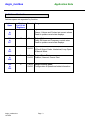
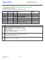
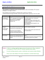
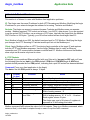
AEGIS_Modbus
Ethernet TCP
CONTENTS
1. Overview
2. Address Contents
2.1 Current Values of Sensors, Meters, Contact Sets
2.2 Current Values of ON/OFF Relays and Frequency
Control Outputs
2.3 Current State of Sensors, Meters, Contact Sets
2.4 Current State of ON/OFF Relays and Frequency
Control Outputs
2.5 Control State of ON/OFF Relays and Frequency
Control Outputs
3. Aegis_Modbus Client
4. Socket & Packet Structures
4.1 TCP Packets
4.2 Floating Point & Integer-to-Bit Conversion
Application Note
Aegis_modbus
1. Overview
Ethernet Modbus TCP implementation of a Modbus slave @ Modbus address 1, on the default
Modbus port number 502 using the static IP address user set for the Aegis controller, defaulted to
10.10.6.106.
Supports Modbus command 0x03, ‘Read Holding Registers’, where each register returns a 16 bit, 2
byte integer, in ‘big endian’ format, most significant byte first.
The address space for command 0x03, ‘Read Holding Registers’ defines 4 byte floating point return
values so each controller value must be read as 2 sequential addresses and converted by the client
application to a IEEE 754 32 bit floating point ( IEC1131, Intel single precision real ) ,1 bit sign, 8 bit
exponent and 23 bit value/mantissa. The 4 byte, 2 register floating point number is sent ‘big endian’.
Details of the Modbus TCP-IP message header ( www.modbus.org/specs.php ) and the binary-tofloat conversion and error handling are typically handled by the Modbus client for your EMS/DCS
HMI.
The implementation returns either the requested holding register values using the Modbus Ethernet
message format or one of the following exception codes:
Exception
0x01
0x02
0x06
Name
Illegal Function
Illegal Data Address
Busy
Cause
Command not supported by controller
Start or Span address out of range
Controller busy with another request.
User Configured: Disabled I/O, Sensor Driver Cards, Digital Inputs
Aegis controller users may elect to disable unused I/O to remove clutter from the controller LCD
display and to simplify using the browser HMI. To prevent exceptions due to reading disabled I/O,
each disabled I/O returns a defined, default value out of the range of possible values for enabled I/O.
Zero is a possible value for enabled I/O.
Aegis controllers may have a variety of sensor driver cards installed in the C-D and E-F driver slots.
Some controllers may use these slots for pH & ORP, others for corrosion rate, others for 4-20mA
outputs …. The Modbus response to reading these values is in the units of the driver card; ORP in
mV, corrosion rate in mpy, temperature in C or F, conductivity is uS…..
The 12 Aegis digital inputs ‘O’ to ‘Z’ may be user configured as contact set inputs or volume
measurement inputs. Contact sets return the time closed in seconds and volume inputs return the
volume from midnight.
Aegis_modbus.doc
12/12/08
Page: 2
Application Note
Aegis_modbus
2. Address Contents
Address spans are separated by function.
Address
Span
100
to
151
Total
# of 16 bit
Registers
52
Format Usage
Float
Input Values
Sensor, Volume and Contact set current values.
Read to update current state displays.
Output Values
Relay ON times and Frequency control rates.
Read to update current state displays.
200
to
217
18
Float
300
to
325
26
2 Byte
UInt16
Input State-Status: Enabled, Alarmed
4-20mA Output Cards: Interlocked, Loop Open
& Manual Mode
400
to
408
9
2 Byte
UInt16
Output State-Status:
Enabled, Alarmed, Events Exist
500
to
508
9
2 Byte
UInt16
Output Control State:
Configuration & Operational state information
Aegis_modbus.doc
12/12/08
Page: 3
Application Note
Aegis_modbus
2.1 Current Values of Sensors, Meters, Contact Sets
Addresses 100 to 151 inclusive,
Request 52 registers starting @ 100 to get all current values
Address
/ IO
100 / A
102 / B
104 / C
106 / D
108 / E
110 / F
112 / G
114 / H
116 / I
118 / J
120 / K
122 / L
124 / M
126 / N
128 / O
130 / P
132 / Q
134 / R
136 / S
138 / T
140 / U
142 / V
144/ W
146 / X
148 / Y
150 / Z
# of 16bit
Registers
2
2
2
2
2
2
2
2
2
2
2
2
2
2
2
2
2
2
2
2
2
2
2
2
2
2
Aegis_modbus.doc
12/12/08
Format Type
Float
Float
Float
Float
Float
Float
Float
Float
Float
Float
Float
Float
Float
Float
Float
Float
Float
Float
Float
Float
Float
Float
Float
Float
Float
Float
Sensor, Conductivity
Sensor, Temperature
Sensor, Varies with driver
Sensor, Varies with driver
Sensor, Varies with driver
Sensor, Varies with driver
Sensor, 4-20mA Input
Sensor, Varies, phantom
Sensor, Varies, phantom
Sensor, Varies, phantom
Sensor, Varies, phantom
Sensor, Varies, phantom
Sensor, Varies, phantom
Sensor, Varies, phantom
Volume or Contact Set
Volume or Contact Set
Volume or Contact Set
Volume or Contact Set
Volume or Contact Set
Volume or Contact Set
Volume or Contact Set
Volume or Contact Set
Volume or Contact Set, phantom
Volume or Contact Set, phantom
Volume or Contact Set, phantom
Volume or Contact Set, phantom
Page: 4
Notes
1
2
3,
3
3
3
4
3, 5
3, 5
3, 5
3, 5
3, 5
3, 5
3, 5
3, 6
3, 6
3, 6
3, 6
3, 6
3, 6
3, 6
3, 6
3, 6, 7
3, 6, 7
3, 6, 7
3, 6, 7
Application Note
Aegis_modbus
2.1 Current Values of Sensors, Meters, Contact Sets cont.
1.
Notes:
Controller input ‘A’ is a fixed conductivity sensor measured in uS.
2.
Controller input ‘B’ is a fixed temperature sensor. Units are either ‘F’ or ‘C’ depending on
system level units selection of ‘metric’ or ‘US units’.
3.
Sensor driver cards may be installed in slots C-D and E-F. Conductivity, temperature, pH, ORP
4-20mA input & output and corrosion rate cards are currently available.
4.
Controller input ‘G’ is a fixed 4-20mA input.
User defines units of value represented by the current loop input.
5.
Phantom sensor inputs ‘H’ to ‘N’ don’t physically exist within the controller.
They are used for Manual and Calculated values like ppm and Inventory and are displayed and
used as other sensor values.
6.
Controller inputs ‘O’ to ‘Z’ may be user configured as Volume (Water meter) or Contact Sets
(Flowswitches & Interlocks).
If Volume, value is volume from midnight.
If Contact Set, value is time closed where time closed is zeroed each time the contact set
opens.
7.
Phantom volume-contact set inputs ‘W’ to ‘Z’ don’t physically exist within the controller.
They are used for Calculated values like ‘sum’,’copy’ and ‘mirror’ and are displayed and used
as other volume-contact set values.
all
Disabled inputs return -100000
Aegis_modbus.doc
12/12/08
Page: 5
Application Note
Aegis_modbus
2.2 Current Values of ON/OFF Relays and Frequency Control Outputs
Addresses 200 to 217 inclusive,
Request 18 registers starting @ 200 to get all current values
Address
/ IO
200 / 1
202 / 2
204 / 3
206 / 4
208 / 5
210 / 6
212 / 7
214 / 8
216 / 9
1.
2.
# of 16bit
Registers
2
2
2
2
2
2
2
2
2
Format Type
Float
Float
Float
Float
Float
Float
Float
Float
Float
Relay, Seconds ON
Relay, Seconds ON
Relay, Seconds ON
Relay, Seconds ON
Relay, Seconds ON
Frequency, Rate 0-100%
Frequency, Rate 0-100%
Frequency, Rate 0-100%
Frequency, Rate 0-100%
Notes:
Relay ON time in seconds this actuation. 0 = OFF.
Reset to zero @ controller clock (site time) midnight.
Range 0 to 86400.
Refer to Diagnostic addresses for status & current state
(Blocked, Interlocked, Alarmed..).
Current rate 0.00 to 100.00%. 0 = OFF.
Refer to Diagnostic addresses for status & current state
(Blocked, Interlocked, Alarmed..).
3.
Disabled outputs return -100000
Aegis_modbus.doc
12/12/08
Page: 6
Notes
1
1
1
1
1
2
2
2
2
Application Note
Aegis_modbus
2.3 Current State of Sensors, Meters, Contact Sets
Addresses 300 to 325 inclusive,
Request 26 registers starting @ 300 to get all current states
Address
/ IO
300 / A
301 / B
302 / C
303 / D
304 / E
305 / F
306 / G
307 / H
308 / I
309 / J
310 / K
311 / L
312 / M
313 / N
314 / O
315 / P
316 / Q
317 / R
318 / S
319 / T
320 / U
321 / V
322/ W
323 / X
324 / Y
325 / Z
1.
2.
# of 16bit
Registers
1
1
1
1
1
1
1
1
1
1
1
1
1
1
1
1
1
1
1
1
1
1
1
1
1
1
Format Type
16 bit
16 bit
16 bit
16 bit
16 bit
16 bit
16 bit
16 bit
16 bit
16 bit
16 bit
16 bit
16 bit
16 bit
16 bit
16 bit
16 bit
16 bit
16 bit
16 bit
16 bit
16 bit
16 bit
16 bit
16 bit
16 bit
Sensor, Conductivity
Sensor, Temperature
Sensor, Varies with driver
Sensor, Varies with driver
Sensor, Varies with driver
Sensor, Varies with driver
Sensor, 4-20mA Input
Sensor, Varies, phantom
Sensor, Varies, phantom
Sensor, Varies, phantom
Sensor, Varies, phantom
Sensor, Varies, phantom
Sensor, Varies, phantom
Sensor, Varies, phantom
Volume or Contact Set
Volume or Contact Set
Volume or Contact Set
Volume or Contact Set
Volume or Contact Set
Volume or Contact Set
Volume or Contact Set
Volume or Contact Set
Volume or Contact Set, phantom
Volume or Contact Set, phantom
Volume or Contact Set, phantom
Volume or Contact Set, phantom
Notes
1
1
1,2
1,2
1,2
1,2
1
1
1
1
1
1
1
1
1,3
1,3
1,3
1,3
1,3
1,3
1,3
1,3
1,3
1,3,
1,3
1,3
Notes:
Enabled 0x01, Bit 0 =1, Alarmed 0x02, Bit 1 =1,
Used for Captured Sample Controls 0x40, Bit 6=1
Unused Bits 2,3 & 5 to 15
4-20mA Outputs Cards Only
Interlocked 0x01, Bit 1 = 1, Loop Open 0x40, Bit 6 =1, Manual Mode 0x80, Bit 7=1
Aegis_modbus.doc
12/12/08
Page: 7
Application Note
Aegis_modbus
2.4 Current State of ON/OFF Relays and Frequency Control Outputs
Addresses 400 to 408 inclusive,
Request 9 registers starting @ 400 to get all current states
Address
/ IO
400 / 1
401 / 2
402 / 3
403 / 4
404 / 5
405 / 6
406 / 7
407 / 8
408 / 9
1.
# of 16bit
Registers
1
1
1
1
1
1
1
1
1
Format Type
16 bit
16 bit
16 bit
16 bit
16 bit
16 bit
16 bit
16 bit
16 bit
ON/OFF Relay,
ON/OFF Relay,
ON/OFF Relay,
ON/OFF Relay,
ON/OFF Relay,
Variable Frequency
Variable Frequency
Variable Frequency
Variable Frequency
Notes
1
1
1
1
1
1
1
1
1
Notes:
Enabled 0x01, Bit 0 =1,
Alarmed 0x02, Bit 1 =1,
Events Exist 0x08, Bit 3 =1
(Timed event for Relays 1..5. Volume feed events for Variable Frequencies 6...9)
Unused Bits 2 & 4 to 15
Aegis_modbus.doc
12/12/08
Page: 8
Application Note
Aegis_modbus
2.5 Control State of ON/OFF Relays and Frequency Control Outputs
Addresses 500 to 508 inclusive,
Request 9 registers starting @ 500 to get all control states
Address
/ IO
500 / 1
501 / 2
502 / 3
503 / 4
504 / 5
505 / 6
506 / 7
507 / 8
508 / 9
# of 16bit
Registers
1
1
1
1
1
1
1
1
1
Format Type
Bit /Value
0 / 0x01
Control State
ON =1
16 bit
16 bit
16 bit
16 bit
16 bit
16 bit
16 bit
16 bit
16 bit
1 / 0x02
2 / 0x04
3 / 0x08
Interlocked =1
Limited =1
Varying Cycles = 1
4 / 0x10
5 / 0x20
6 / 0x40
7 / 0x80
8 / 0x100
Unused
Off-On-Alarm = 1
Blocked = 1
Unused
Special Control =1
9 / 0x200
Sequential Control =1
10 / 0x400
Forced ON =1
11 / 0x800
Owed =1
12 / 0x1000
13 / 0x2000
Unused
Blocking =1
14 / 0x4000
15 / 0x8000
Midnight Reset =1
Fused =1
Aegis_modbus.doc
12/12/08
ON/OFF Relay,
ON/OFF Relay,
ON/OFF Relay,
ON/OFF Relay,
ON/OFF Relay,
Variable Frequency
Variable Frequency
Variable Frequency
Variable Frequency
Control State
Current state of Relay ON|OFF
or Variable frequency drive
Turned OFF by one or more contact sets opening.
Exceeds Relay ON time limit of feed volume limit.
Control typically on a ratio of conductivities and limited by
a maximum conductivity.
Turns OFF when Limited
Turned OFF when one or more other outputs turns ON
Controlled by a ‘Special Control’… Captured Sample,
Base Feed….
2nd phase of an Q:P sequential volume control;
ON for 'P'
Prebleed has turned output ON. Bypass setpoint ON/OFF
but update control value.
Time or Volume owed. Count down if not blocked,
interlocked, limited…
Output is blocking another output, used with ‘Blocked’ to
resolve sequential & circular blocks.
Output is reset at midnight if limited.
Relay output OFF, AC fuse OPEN
Page: 9
Application Note
Aegis_modbus
3. Aegis_Modbus Client
Aegis_Modbus is a lightweight support and demonstration client for the Modbus TCP services
embedded in the Aegis controller.
Aegis_Modbus can be installed on a Windows XP or Vista PC or notebook.
It communicates with Aegis controllers via the site Ethernet LAN or by using a cross-over cable.
Client Service
Function
Verify Aegis IP
& HTTP Server
HTTP connects to the Aegis with
user defined IP & password.
Displays the system XML
response file.
Single &
Timed Repeat
Commands.
User defined start address & span.
Client enforces valid addresses.
Client deconstructs Modbus
response packet showing both
byte sets and resulting I/O values.
Force Fault
Executes user selected fault and
displays deconstructed response
packet.
Usage
Verifies IP and Ethernet communications,
controller powered up, running and
communicating
Identifies the Aegis controller by serial
number so you know you’re talking to the
correct controller.
Valid Aegis password required to use
Aegis_Modbus.
Used for byte order conversion
and bit extraction problems.
Shows you byte order, byte content and
converted values,
Aegis_Modbus auto-corrects Address and
span.
You client may get fault responses & Force
Fault shows you the error packet.
Sidebar: A ‘Client’ is a software application that consumes the services of a ‘Server’ application.
Your browser is a ‘Client’ for the HTTP ‘Servers’ accessed via the Internet.
Your site’s building automation system or distributed control system includes a Modbus
TCP
‘Client’ used to talk to Modbus TCP Servers embedded in controllers like the Aegis.
Aegis_modbus.doc
12/12/08
Page: 10
Application Note
Aegis_modbus
4. Socket & Packet Structures
This section is of interest to users with Modbus client application problems.
IP: The Aegis uses the same IP address for both HTTP/browsing and Modbus. Modifying the Aegis
IP address for your network changes the address for browsing, Trackster and Modbus.
Sockets: The Aegis can support concurrent browser-Trackster and Modbus users on separate
sockets. Modbus requires a TCP socket and a binary ( non-ASCII ) data stream. If you are required
to set the socket RX/TX buffers, use a minimum of 512 bytes. Internally the Aegis limits the Modbus
RX/TX buffers to 255 bytes. Typically, your OS will set socket buffers much larger than 512.
Port: Modbus is fixed at port 502, the default, assigned port for TCP Modbus. Modifying the Aegis
port changes the HTTP browsing & Trackster access port but not the Modbus port.
Client: Aegis_Modbus verifies an HTTP functioning Aegis controller at the target IP and captures
both the HTTP and Modbus responses. Use the Aegis_Modbus client to verify an Ethernet
connection and TCP communication between controller and PC. Modbus clients send the Modbus
slave a byte set & receive a byte set in return.
4.1 TCP Packets
Wireshark (or your preferred Ethernet sniffer) with your filter set to ‘tcp.port == 502’ and you’ll see
the following bytes set as ‘data’ in the PSH packets. SYN/client, SYN-ACK/Aegis & ACK/client
packets should precede the first PSH packet, indicating that a port 502 socket has been established
Command (From your client application to the Aegis)
The data in the first PSH packet is always 12 bytes.
Bytes
0-1
2-3
4-5
6
7
8-9
Content
(in hex)
00 01
00 00
00 06
01
03
00 64
10-11
00 1C
Function
Notes
Sequence
Protocol
Message size in bytes
Controller Address
Modbus Command
Start address/register
Quantity of registers
from Start
Ignored by Aegis; echoed
Always 0x0000. Ignored by Aegis; echoed
Big endian, MSB first. Bytes following byte 5
0x01 Default, Aegis also accepts Address=0xFF
Always 0x03,
Big endian, MSB first. 0x0064 = 100
Start of analog sensors, ‘A’
Big endian, MSB first. 0x001C = 28
End of analog sensors, ‘N’, ‘A’ to ‘N’ - 14 values.
Each register returns 2 bytes.
The Aegis uses a set of 4 bytes or 2 registers to
represent a 32 bit floating point value.
Modbus command 0x03 returns the value of a16 bit register. There is no Modbus command, which
returns a float ( a look-back to simpler times) so users co-opt the 0x03 command.
Aegis_modbus.doc
12/12/08
Page: 11
Application Note
Aegis_modbus
4.1 TCP Packets cont.
Normal Response (From the Aegis to your client )
The data in the second PSH packet is always the 2 bytes + 2 x Quantity from Start value.
If Start Address= 100 & Quantity = 28, the data set would be 58 bytes plus the leading 6 bytes.
Unlike serial Modbus, there is no CRC since the Ethernet tcp/ip protocol provides this service.
Bytes
0-1
2-3
4-5
Content
(in hex)
00 01
00 00
00 3A
Sequence
Protocol
Message size in bytes
6
7
8
01
03
38
Controller Address
Modbus Command
Byte count
9-12
01 02
03 04
Start floating point data
in 4 byte chunks
Requested address
Data, 4 bytes per value
End floating point data
13-60
61-64
01 02
03 04
Function
Notes
Echoed from the Command
Echoed from the Command
Big endian, MSB first. Bytes following byte 5
0x003A = 58 bytes
Always 0x01.
Always 0x03.
Number of requested addresses/registers x 2
Echo of ‘Qty of Registers’ x 2
Big endian, MSB first. 0x0064 = 100
Start of analog sensors, ‘A’
If Quantity = 28, 54 bytes representing 14, 4
byte values would be included in the response
Big endian, MSB first. 0x001B = 127
End of analog sensor ‘N’
Error Response (From the Aegis to your client )
If you issue a command other than 0x03 and/or request invalid addresses-registers you’ll get an error
response.
Bytes
0-1
2-3
4-5
Content
(in hex)
00 01
00 00
00 03
6
7
01
83
Controller Address
Modbus Command
with bit 7 set
8
02
Error codes
Aegis_modbus.doc
12/12/08
Function
Notes
Sequence
Protocol
Message size in bytes
Echoed from the Command
Echoed from the Command
Big endian, MSB first. Bytes following byte 5
0x0003 = 3 bytes
A message size of 3, ‘data’ size = 9, indicates an
error.
Always 0x01.
Always 0x03 ‘or’ed with 0x80 = 0x83
Byte 7 greater than 127 decimal indicates an
error.
0x01: Modbus Command not 0x03
0x02: Start Address/Register or Quantity
out of range.
0x06: Busy, dealing with another request.
An unlikely error.
Page: 12
Application Note
Aegis_modbus
4.2 Floating Point & Integer-to-Bit Conversion
Conversion detail is usually hidden from you by your Modbus client application which correctly aligns
the incoming byte stream with 32 bit-to-floating point or 16 bit integer-to-bit conversions.
Floating point data is transmitted from the Aegis in 4 byte chunks, MSB first (Big-Endian) using IEEE
754, 32bit, single precision format.
If you are faulting on the floating point conversion, preview the byte order using the Aegis_Modbus
client. Intercept the byte stream and reverse the order of the floating point byte sets. This is how
Aegis_Modbus converts the BigEndian byte sequence to a Windows OS floating point.
If your bit conversions-to-state information are faulting, use Aegis_Modbus to verify that you are
getting the correct bytes and then switch the byte order of each 16 bit field prior to bit-state
extraction.
LittleEndian & BigEndian
When Modbus was new, computers were BigEndain & the Modbus spec reflected this, sending byte
level data in BigEndian format, most significant byte first. It was easy to convert byte sets to signed
integers.
Windows systems are LittleEndian, like the Aegis’ microcontroller.
With luck, this distinction will be obscured by your Modbus client which will convert the BigEndian
byte stream back to LittleEndian prior to converting byte streams to floats & 16 bit integers (ushort).
Your client may require you to set an option defining the Endian preference. If the Modbus client
values don’t match the Aegis LCD display values, switch the Endian preference in your client.
Aegis_modbus.doc
12/12/08
Page: 13