1
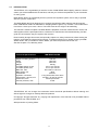
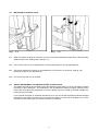
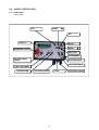
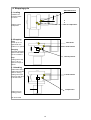
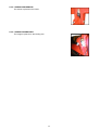
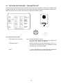
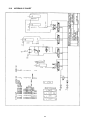
December 18, 2002
a404H20E.WPD
USER'S MANUAL MINI WRAP 404 EH
CHAP.
CONTENTS
PAGE
1.0
INTRODUCTION
3
2.0
SAFETY PRECAUTIONS
4
3.0
GENERAL INFORMATION ON BALE WRAPPING
4.0
SETTING UP / MOUNTING OF THE MACHINE
8
5.0
MOUNTING OF PLASTIC FILM
9
6.0
ADJUSTMENTS / USE
10
7.0
OPERATION INSTRUCTION
11
8.0
INSTRUCTIONS CONTROL BOX
12
9.0
PERIODIC MAINTENANCE
19
6
10.0
CHECK POINTS BEFORE TROUBLESHOOTING
11.0
TROUBLE SHOOTING
21
12.0
ELECTRIC, HYDRAULIC CHART
23
13.0
SPARE PARTS LIST
25
14.0
WARRANTY TERMS
52
WARRANTY CARD
53
1
20
MINI WRAP 404 Electric, Hydraulic bale wrapping machine.
4
10
9
2
1
5
3
8
6
7
1.
2.
3.
4.
5.
Roller
Support roller
Tilt frame
Prestretcher
Cutter
6.
7.
8.
9.
10.
2
Frame plate
Support wheel
Wheel
Load arm
Fork clamp
1.0
INTRODUCTION.
TELLEFSDAL A.S congratulates you with the choice of MINI WRAP bale wrapping machine. We are
certain you will be satisfied with the machine, and that you will have the pleasure of your investment
for many years.
MINI WRAP 404 EH is hydraulically driven by the tractors hydraulic system, and is easy to operate
with the Lyctronic control box.
The MINI WRAP 404 EH is designed to be a simple and effective bale wrapping machine square
bales. MINI WRAP 404EH is estimated for wrapping bales of grass, hey or straw, it can handle bales
from 35cm x 45cm up to 50cm x 50cm. The bales must have a weight of at least 35kg.
This manual is meant to explain how MINI WRAP is prepared, mounted, used and how it works, and
shall together with the spare part's list be a reference for maintenance and troubleshooting. So take
good care of the books, they are a part of the machine.
Read carefully through this manual, and specially chapter 2.0, safety instructions, before starting the
machine, and follow the instructions thoroughly. If problems should occur, please contact your MINI
WRAP dealer. Ask your dealer for advice before you make the problem worse than it is.
See also chapter 13.0, Warranty terms.
Technical Specifications
MINI WRAP 404 EH
Height in working position
Width
Length
Weight
Turntable speed, recom.
Turntable speed, max.
Bale size, max.
Bale weight, min.
Prestretcher
Hydraulic connection
Oil pressure / amount, min.
Oil amount, max.
Counter pressure, max.
930 mm
1640 mm
3200 mm
625 kg
22 rev. per minute
27 rev. per minute
500 x 500 x 1150 mm
35 kg
500 mm
1 sing.work.outlet,+free return
100 bar / 15 liter per minute
30 liter per minute
10 bar
TELLEFSDAL A.S can change the construction and/or technical specifications without warning and
without rights to changes on already delivered products.
© Copyright. All rights reserved. Any copying and reproduction of this manual is not permitted without
permission from TELLEFSDAL A.S.
With precaution of printing failure.
3
2.0
SAFETY PRECAUTIONS.
TELLEFSDAL A.S does not take the responsibility for damages that may occur on machine,
persons or other equipment, because of the machine NOT being used as described in this
manual, or because of the safety precautions NOT being followed.
2.1
SAFETY EQUIPMENT.
Before using the machine, make sure that all guards and covers are securely fitted. The machine must
not be operated if a function does not work as described later in this manual. (See chapter 2.5).
2.2
BECOME FAMILIAR WITH THE OPERATIONS OF THE MACHINE.
If you are unsure how to operate the machine properly, either use of or maintenance to your Mini Wrap,
please contact your Mini Wrap dealer.
2.3
ADJUSTMENTS' / MAINTENANCE.
Turn off the tractor and discharge the oil pressure before performing any adjustment or maintenance on
the machine. Remember that a well-maintained machine is a safe machine.
2.4
IMPORTANT!
MAKE ALWAYS SURE THAT NOBODY IS INSIDE
THE MACHINE'S WORKING AREA WHEN IT'S IN USE.
SAFETY DISTANCE IS 5 METRES
THE MACHINE MUST NEVER BE OPERATED BY PERSONS WHOM DOES NOT KNOW ENOUGH
ABOUT HOW TO SAFELY OPERATE THE MACHINE, OR BY PERSONS UNDER 16 YEARS OF AGE.
Fig. 2-1
4
Fig. 2-2
2.5
2.6
DANGEROUS AREAS.
TELLEFSDAL A.S has given the safety to the operator the highest priority, but it is still impossible to
secure oneself of every danger area on the machine. Therefore we will now go through some of the
dangers that can occur when using the Mini Wrap bale wrapper.
1.
Be specially aware of the rotating turntable.There is a danger of being squeezed between the
turntable and the main frame.
2.
When the wrapping of a bale is complete and tipped off the machine, the turntable has to be tipped
back before wrapping next bale. When the middle frame with turntable is lowered, there is a
squeeze danger between the middle frame and the main frame on both sides and in the back end
of the machine. Keep therefor fingers and feet in safe distance. (Fig. 2-2).
3.
When tipping the turntable, the bale will roll free off the machine. Staying behind the machine can
cause danger for "overrunning" by the bale when it rolls off. Make therefor sure that nobody is
behind the machine when unloading.
WHILE WRAPPING.
Please keep your hands on the controller during the wrapping proses.
The machine is to stand horizontally while the wrapping takes place. Make sure that nobody comes into
the working area of the machine,
2.7
TRANSPORTING.
When transported on a public road there are certain safety measures that must be taken:
1.
Make sure that the lift arm is in a raised position.
2.
Make sure that the locking bolts on lift arm and the fall damper are mounted.
3.
Make sure that the machine does not cover the tractors' lights. If necessary, mount extra lights.
5
3.0
GENERAL INFORMATION ON BALE WRAPPING.
3.1
THE PRINCIPLE.
The advantages of round bale ensilage are many, and include fewer feed units, a flexible harvesting
system, large capacity and the possibility of selling feed units.
In principle, the same fermentation processes occur whether the fodder is placed in a silo or pressed into
bales and packed in plastic, i.e. lactic acid fermentation in anaerobic conditions. The oxygen in the bale
must be exhausted before fermentation begins.
The grass should be dried to approximately 30-40% solid content. The solid content can be determined
by twisting the grass by hand. If drops of liquid are forced out of the grass, the solid content is less than
25%. Low solid content, (wet grass), can lead to increased butyric acid fermentation if preservatives are
not added to the grass. If the solid content is too high, (over 50%), normal fermentation will not take place
and there will be enough oxygen in the bale to produce mould fungus.
3.2
THE BALER.
It is vital that the baler produces compact, well-formed bales, as misshapen bales can be difficult to wrap.
Baling will also often take longer, thereby increasing the amount of plastic used.
3.3
TYPES OF PLASTIC.
A good type of plastic with good adhesive properties, and which is recommended for bale wrapping, must
be used. The thickness of the plastic foil should be at least 25 µ. (25/1,000 mm). In order that the plastic
tightens sufficiently around the bale, it is stretched before being wrapped, so it is somewhat thinner when
it is put on the bale. With short-term storage, (up to eight weeks), it is recommended that bales have a
minimum of four layers of plastic at the thinnest points, with at least 52-53% overlap.
For long-term storage, or when the grass is wet when it is wrapped, the bale should have 90-100 µ plastic,
(6 layers), and the same amount of overlap. If thinner plastic is used, more layers should be applied. If
it is very hot the plastic will be stretched further, and more layers should be applied. It is better to have
slightly too much than too little plastic on the bale.
From experience, light plastic produces slightly lower temperatures within the bale, and tends to improve
feed quality.
3.4
STORAGE LOCATION.
Care should be taken in finding a suitable location for the storage of bales. The storage location should
preferably be prepared before the bales are laid out. An elevation close to well-drained roads is
recommended. If the wrapped bales are simply placed on stubble there is a danger of the plastic being
pierced. A tarpaulin or a thin layer of sand should therefore be laid where the bales are to be stored over
the winter.
Bales should be stored in the shade as far as possible. This reduces the danger of air leakage in the
bales. A bale which is stored in sunlight and which therefore undergoes greater swings in temperature
"pumps in" a great deal of air in comparison to a bale which is stored in the shade. According to "Teknik
for Lantbruket" [Technology for Agriculture] in Sweden, a bale which is stored in the shade has only 40%
of the air leakage of a bale which is stored in sunlight.
3.5
STACKING / PROTECTION.
If bales are hard and well formed, they can be stacked vertically, but loose and misshapen bales with low
solid content should not be stacked higher than one layer, as this could easily cause deformity and the
danger of runoff will be increased.
Bales can also be stored on their sides. The layer of plastic is thicker here, providing greater protection
against piercing.
Bales should be covered with a tarpaulin or a fine-mesh net to protect against birds and small rodents.
If the plastic is pierced, it must be sealed with weatherproof, hard-wearing tape, preferably under the
outermost layer of plastic. Ensure that the hole is adequately sealed.
6
3.6
The best wrapping results are obtained by...
1.
...harvesting the grass early.
2.
...drying it out to 30-40% solid content. If there is a danger of rain, bale and wrap the
grass anyway.
3.
...taking care not to mix any earth in with the grass.
4.
...using a baler which produces even, firm bales.
5.
...wrapping the bales soon after baling, never later than two hours afterwards.
6.
...using a good type of plastic and six layers of plastic. This removes the need to use
preservatives.
7.
...storing bales in the shade to reduce the danger of air leakage.
7
4.0
SETTING UP / MOUNTING OF THE MACHINE.
4.1
Mount the frame plate.
The frame plate is positioned enabling the machine to be parallel with the ground when it is connected
to the tractor.
4.2
Mount the loading arm and adjust the width on the lift arm in accordance with the bales diameter.
Adjust the loading arms end stopper so that the bale will be placed in the middle of the table when
loading.
4.3
Place the pre-stretcher in the pre-stretcher cylinder.
Adjust the height on the pre-stretcher so that the middle of the plastic meets with the bale’s center.
4.4
Mount the arm for the automatic plastic film to the table.
4.5
Lubricate the machine.
4.6
Check that all the bolts and nuts are tightened, specially the wheel bolts.
4.7
Remove the safety bolts used under transportation from the loading arm, insert the safety bolts into the
parking holes.
4.8
Connect the machine to the tractors rear trailer hitch.
4.9
HYDRAULIC CONNECTION.
The hydraulic hoses between machine and tractor are equipped with 1/2" ISO male quick-couplers.
Discharge the oil pressure before you connect the oil hoses. Use the tractors' hydraulic lever. Connect
the hoses so that the turntable rotates counterclockwise.
To make sure that the balewrapper works properly, the tractors' oil pressure has to be at least 100 bar.
If you are unsure of what oil pressure the tractor gives, or what oil pressure the balewrapper receives,
please contact your machinery dealer.
NB! When connected to a tractor with closed centre (ex. JOHN DEERE) the central duct of the valve must
be plugged.
4.10 CHECK LIST.
Before using the machine it is recommended to follow this check list:
1.
Make it a habit to discharge the oil-pressure before connection or disconnection of the hydraulic
hoses. (Use the tractors hydraulic control lever).
2.
Hose with BLUE CAP = RETURN OIL.
3.
Hose with RED CAP = PRESSURE.
4.
Tie up loose hoses so that no squeeze damages occur.
5.
Start the tractor and try out the functions. (It shall rotate counterclockwise).
6.
Check all connections, hoses and couplings. If there is any oil-leakage, it should be rectified
immediately.
Your MINI WRAP bale wrapper has been tested in practical operation in approx. 2 hours at the
factory.
8
5.0
MOUNTING OF PLASTIC FILM.
Fig. 5-1
Fig. 5-2
5.1
When the plastic roll shall be mounted, you have to hold the prestretcher-rollers aside, Hold the rollers
aside and put on the holding hook. (See fig. 5-1).
5.2
Place a reel of film on to the prestretcher's holding axle and put on the springloaded lock.
5.3
Pull the film between the rollers on the prestretcher in the direction of the arrow. (See fig. 5-2).
(See also the sign on the prestretcher).
5.4
Pull out the film and tie it to the bale.
5.5
HEIGHT ADJUSTMENT OF PRESTRETCHER / PLASTIC FILM.
The plastic film shall hit at the middle of the bale wrapped, and therefore it can be necessary to adjust
the height of the prestretcher. The prestretcher may be adjusted to different heights. Disconnect the
locking bolt, and adjust the prestretcher so that the plastic hits in the middle of the bale. Replace the
locking bolt and the splint.
If you use 250 mm plastic on a 500 mm prestrecher, then you can use the two distance sleeves to adjust
the height on the plastic roll. There can be mounted one sleeve on each side of the plastic roll, or both
sleeves can be mounted above or below. (see also 6.4 Overlap)
9
6.0 ADJUSTMENT / OPERATING.
6.1
SUPPORT ROLLERS.
Place the bale you want to wrap on top of the rollers. Move the support rollers as tight to the bale as
possible. Make sure that the bale is in centre of the rollers.
6.2
HEIGHT ADJUSTMENT OF PRESTRETCHER.
The prestretcher can be placed in different positions. Disconnect the locking bolt, and adjust the
prestretcher so that the plastic hits in the middle of the bale. Replace the locking bolt and the splint.
6.3
Operating Lyctronic control box
See chapter 8
6.4
REVOLUTION SPEED OF TURNTABLE.
Start the machine by operating the lever inside the tractor. The speed of the turntable is adjusted by the
speed of the tractor engine or how much you move the lever. Adjust this until the turntable speed is
approx. 22 revolutions per minute (Just below 3 seconds per revolution).
The machine can also be equipped with a control valve that makes it easier to adjust the speed. Then
you can have full opening of the lever and adjust the oil-flow to the machine, and by that adjust the speed
of the turntable. This valve is extra equipment.
6.5
OVERLAP.
To control the overlap, stop the machine after a few turns. Use a marker to mark a line on the middle of
the film wrapped on the bale. By the next turn this line should just be covered. It is now possible to use
ether the 500mm or the 250mm film on the MINI WRAP 404EH. The machine is prepared for use with
the 500mm film, when using 250mm film the chains from the turntables main shaft must be lengthened
with the enclosed chain pieces and moved to the largest chain wheels.
10
7.0 OPERATION INSTRUCTION.
We shall now go through a complete wrapping process, from loading to storage place, and explain the
practical use of the MINI WRAP 404EH.
7.1
LOADING.
Load a bale on this machine with the loading arm . Place the bale on top of the rollers, as close to the
middle as possible. Move both support rollers as close to the bale as possible.
7.2
HEIGHT ADJUSTMENT OF PRESTRETCHER.
The height of the prestretcher has to be adjusted so that the plastic film is always hitting the middle of
the bale. (See more about this in chapter 5.5 and 6.2).
7.3
TIPS ON WRAPPING SQUARE BALES.
The MINI WRAP 404EH has on deliverance the rollers inn the middle position. If the bales to be wrapped
are inn some degree larger or smaller than mean measure then the rollers must be moved. (Optimally
the film should meet the bale being wrapped in the middle.) The chain cover must be removed, and the
square-unit moved either inn or out. The chain is adjusted, then the chain-tesion is tightened before finely
the bolts are replaced.
Remember that a hard and well pressed bale will give the best result when packing.
7.4
START.
Remember that the plastic film end must be tied to the bale. This is normally only necessary on the first
bale. Operate the hydraulic lever carefully to make a gently start. To quick start can rip off the plastic film,
and then it has to be tied again.
7.5
OVERLAP.
Control that the overlap is correct. If not, see chapter 6.4.
7.6
HOW MANY LAYERS OF PLASTIC FILM?
When the bale is completely covered with film, read the counter that displays the number of revolutions
done by the turntable. If you don't have a counter, you have to count the revolutions yourself, (or you can
measure the time it takes). This number has to be multiplied by 2 or 3, depending on how many layers
of film you want to have.
* 4 layers - multiply by 2.
* 6 layers - multiply by 3.
7.7
STOP / UNLOADING.
When the wrapping is complete, stop the machine when the tines stand crosswise the tractor. Then lift
the turntable until the bale falls off. The film can stick to the bale, because this is preferred cut off when
loading the next bale.
7.8
NEW BALE.
Lower the turntable down again. Then place a new bale on top of the rollers, (upon the plastic film from
last bale), and start wrapping. Now the plastic film from the last should be cut off.
Fasten the film end, if necessary, with some weatherproof tape.
11
8.0 404 EH CONTROL BOX.
8.1-1 FUNCTIONS
Table model.
EXIT
MENU
SET
DISPLAY
RESET
MENU
EMERGENCY STOP
ADD TOO
IR-TERMINAL
CUTTER OPEN /
CLOSE
ROTATION AUT.
ROTATION MAN.
TABLE UP/DOWN
LOADING ARM
STEERING CABLE
12
FUSE
BATTERY CABLE
8.1-2 OPERATOR MENU
Auto-wrap Controlbox 2000 AW 4000/404
16 mars 2000 JH
Notice:
By pressing "EXIT" more than 3 sek. You allways will be braught back to "Wrap-cycle" ( Wrapp modus)
By pressing "MENU" more than 3 sek, the display contrast will be adjusted. "MENY" up = Stronger MENY down = weaker
Manual operation
Behind the rubberplug on the the rear side of the control box it is placed a switch for manual/automatic operation.
Please notice that the display does`nt work in manuel modus.
Display nbr ( )
Wrap cycle: 0-10
Balecounter 1:
Programing nbr laps/bale
MENU
Adjust flashing numbers
SET:
Change
SET:
Nextl
EXIT:
Store
EXIT:
Store
EXIT:
Store
3. Programing
2
Reset Counters
MENU
Reset
SET:
Enter
Setup
EXIT:
Store
3
SET:
Change
MENU
Version
4
5
6
7
8
9
10
11
12
13
14
15
16
17
18
19
20
21
22
23
404 EH
(with loading arm
404
( Without loadingarm)
700 EH
( Without loadingarm)
EXIT
Store
MENU
4000 EH ( With loadingarm)
Press SET to change settings
Auto load bale with load arm
4000
700
404
404 w/arm
Yes
NO
Raise load arm above sensor duration
8,,5
5.0
Load arm, up to down delay
0.0
0.0
Lower load arm, on sensor duration
0.1
0.1
Yes
Yes
Wait for startsignal after load
Rotate slow duration
2.0
2.0
2.0
2.0
1.5
2.0
6.0
6.0
5.0
2.0
5.0
Rotate fast, start of final rev.
0.0
0.0
0.5
0.5
Rotate slow duration
1.5
1.5
1.5
1.5
Revolution until fil release
Realese film
Stop table duration
1.5
0.2
0.2
0.0
0.0
Yes
Yes
Yes
Yes
3.6
2.0
3.6
2.0
1.3
2.0
1.3
2.3
2.3
1.0
2.0
1.0
Delay, tip upp to tip down.
0.0
0.0
0.0
0.0
Tip down duration
0.3
0.3
0.5
0.5
Yes
Yes
Yes
Yes
Yes
Yes
Yes
Yes
No
No
No
No
Rotate load position sensor included
Yes
No
No
Yes
Load arm up/down included
Yes
No
No
Yes
Wait for startsignal before offload
If no cutsensor:tip up, until cut
Film cut duration
Tip up (after cut) duration
Rotate after tip
MENU :
Adjust flashing
numbersl
EXIT:
Store
MENU :
Adjust flashing
numbers
EXIT:
Store
Sensor setup Press SET to enter
SET:
Enter
24
25
26
27
Table Is horizontal sensor included
Cutnow sensor included
13
Actual RPM:
(Alarm limits :28-35)
Actual wrapping speed
Alarm on 28 rpm Stop 35 rpm
HOME
28
Balecounter
SET:
enter
29
Reset possible ?
Yes
Bales total for all 9 balecounters
30
31
32
33
Bales machine total
No
Balecounter 1: 2: 3:
Balecounter 4: 5: 6:
Yes
Yes
Balecounter 7: 8: 9:
Yes
EXIT:
Store
35
36
Reset possible ?
Yes
No
Working hours since last reset
Working hours machine total
SET:
Adjust
MENU
Reset
EXIT:
Store
SET:
Enter
Dänish
English
Nederlands
Francais
Deutsch
MENU:
Adjust flashing
numbers
EXIT:
Store
MENU:
Adjust flashing
numbers
EXIT:
Store
SET:
Enter
Home
34
Audioalarm &
Display
MENU:
Reset
SET:
Enter
Working HRS:
Machine tot:
Language :
SET:
Adjust
37 Audio alarm
38 Display contrast
39 Display light
On
100
On
EXIT:
Store
SET:
Enter
Hardware test.
40
Description
41 Supply voltage
SET:
A signal change
the displayed
out/in put from
0 into 1.
Present voltage
Last drop to
Last registrated drop of voltage.
42 Test keys pressed 000.000
43 Test switches aktivated 00.00.00.00.00
44 Relays, 0=off.AMP nbr 0--.0000.000-.-00
(Test 6 programbuttons)
(Test av 5 stk funktion switches)
( Test relayoutputs. AMP sprocket 1-16 )
Nbr 10,11,12.13,14,15,16 are indicated with A,B,C,D,E,F,G
45 Sensor (input) TEST Press SET to enter
SET:
Enter
46 Rotate (load)
Rotate tip
47 Loadingarm down
48
Cut/horizontal
Infra red Rec.Input
Nr 1
Nr 2
Sensor test countersignal
Sensor test tip
1 = Yes 0= No
1 = Yes 0= No
Nr 3
Sensor test loadarm
1 = Yes 0 = No
Nr 15
Sensor test table horizontal
Sensor test Infra red input
1 = Yes 0 = No
1 = Yes 0 = No
14
SET:
A signal change
the displayed
out/in put from
0 into 1.
4. Wrappingcycle
Aktivited sensors
Loadarm down
a. Loading
Loadarm rais
and return back
on sensor
Table is hold in
loadposition
Table in loadposition
b. Wrapping
Start:
Starts up on 1/2
speed and runs
further in 1/1 speed
Table down
Loadarm down
Wrapping
Wrap with adjusted
speed unntil setted
nbr of revolutions.
Unload position
Stop.
Table goes to stop
from 1/1 to 1/2
speed an stops on
sensor.
c. Unloading
Table starts raising
Table stops and the
cutter is closing
Table goes further
to the top and return
to sensor frame.
Loadarm down
Loadposition
Table turns into
loading position
JH 16 feb.2000
15
8.2 SENSOR
8.2-1 INSTALLING THE SENSOR AND MAGNET
The magnet must be mounted on the rotating element, e. g. the table of the wrapper.
The sensor must be installed on a bracket,
distance of
2 - 8 mm.
See the
drawing
below:
securing that the magnet passes the sensor end within a
Please notice:
If the sensor is to be mounted on a
mounting bracket which is
magnetizable (iron), then the
sensor must be placed at least 5 mm
beyond the edge of the mounting
bracket.
Please take notice, so that the cable from the sensor will be protected and not break when the tractor is turning,
or when the hydraulic is used.
8.2-2 MAGNET PLACED ON THE CENTRE AXEL.
On the EM model there is 1 magnet as shown in the picture, on the
EH model there are 2.
8.2-3 SENSOR PLACING.
The upper sensor steers the loading operation.
The lower sensor steers the off-loading
8.2-4 TABLE SENSOR WITH MAGNET.
16
8.2-4 LOADING ARM SENSOR.
The sensor is placed on the frame.
8.2-4 LOADING ARM MAGNET.
The magnet is placed on the loading arm.
17
8.3 THE INFRA-RED RECEIVER / TRANSMITTER SET.
The receiver is connected directly to the monitor via 4 pole connector mounted on the tail. The transition radius
is stated at 30 meter. The actual radius may be as high as 60 meters depending on the battery condition. Sun
filtered windscreens on the tractor will reduce the transmission distance further.
1= negative
2= 12 volt
3= signal
8.3-1 Specification of limits.
Pulse signals from the sensor:
max. 167 pulse signals per second.
min. pulse time: 0,6ms~the magnet must activate the
sensor for 1/10 of the time at 9999 rpm.
Temperature limits:
The Flex Counter is fully operational within -10 to 70 °C.
This does not necessarily apply for the batteries, please
check with your local battery dealer.
Clock:
+/- 0,5%. Has influence on the accuracy of the following
functions: speed (km/h), rpm and working hours.
18
9.0
PERIODIC MAINTENANCE.
9.1
BEARINGS.
All ball-bearings are packed with grease, and do not need any more maintenance.
9.2
PRESTRETCHER.
If the machine is in daily use, the guiding sleeves at the prestretcher should be oiled once a week or
when needed. Sprockets and bearings on the prestretcher should also be oiled when needed.
9.3
CHAINS.
Oil the chains at regular intervals. Take them off once a year for cleaning and oiling. Soak the chains
in oil for 2-3 days and afterwards hang up for 10-12 hours to drain.
After some use, the chain from the motor to the turntable has to be adjusted. Unlock the nuts on the
motor bracket, and tighten up the adjustment.
DO NOT TIGHT TOO MUCH, CAUSE THIS WILL INCREASE THE WEARING OF THE BEARINGS.
The chains on the square rollers also have to be adjusted. There is one chain tightener on each side.
9.4
GEAR.
The shaft in the turn table´s senter (below the cover) must be greased when required.
9.5
HYDRAULIC CYLINDERS.
Make sure that the hydraulic cylinder is closed when storing the machine.
9.6
CLEANING.
The machine should be cleaned and oiled regularly and by the end of the wrapping season.
NB!
When using a steamer, you need to be careful with the electric equipment and bearings.
Keep the counter protected from rain or water.
9.7
QUICK COUPLERS.
Be careful to keep the quick couplers clean and apply the dust caps after use. The connecting hoses
are to be placed in the holders, on the side of the machine when not in use.
9.8
STORAGE.
The machine should be parked on a dry place during the closed season.
19
10.0
CHECK POINTS BEFORE TROUBLE SHOOTING.
In this chapter we have some general check points that have to be examined first if something is wrong
with the machine. In chapter 11.0 we have a more detailed trouble shooting.
There are two basic assumptions that have to be fulfilled if the machine shall function properly:
1.
2.
10.1
The oil pressure from tractor should be 180 bar.
The return flow of oil has to be as free as possible, max. 10 bar counter pressure.
OIL PRESSURE.
In order to control that the oil pressure into the machine is high enough, there has to be applied a gauge
to the oil pressure hose, for example on the quick coupler.
If the pressure is less than 180 bar, there will be less power for the functions.
OIL AMOUNT.
The oil amount that the tractor delivers must be minimum 15 litres/minute, (Max. allowed oil amount
is 25 litres/minute).
REMEMBER! Large oil amount = Valves get hot. (Small oil tank = insufficient cooling).
10.2
COUNTER PRESSURE.
The counter pressure can be too high. With high counter pressure the machine's functions will get less
power. High counter pressure means also that you need more power to operate the valves.
MAX. ALLOWED COUNTER PRESSURE IS 10 BAR.
If you are in doubt about the counter pressure, arrange a "free return" directly to the tank.
PLEASE CONTACT YOUR DEALER IF YOU ARE IN DOUBT OF ANYTHING.
(Remember always to give your dealer the serial number and production year of your machine
when contacting dealer and when ordering spare parts).
20
11.0 TROUBLE SHOOTING.
BEWARE OF MOVING PARTS WHEN TESTING THE MACHINE.
11.1
11.2
THE MACHINE DOES NOT WORK.
a)
The gage shows that there is enough pressure but there is no reaction from the machine. The
problem can be that one or both of the quick couplers are not opening to let the oil through.
Change the quick couplers.
b)
The counter pressure may be to high.
Max. counter pressure is 10 bar
THE TABLE WILL NOT ROTATE.
a)
b)
The safety valve on the motor, may be leaking, so that the oil passes the motor. Disengage the
valve and check that the piston moves freely.
Check if the oil motor is working.
Ask your dealer for advice BEFORE you make the error larger and more difficult to
repair.
11.3
LOAD ARM, TILT, TABLE OR CUTTER DOS NOT FUNCTION.
The cables have become warped, and must be replaced.
11.4
RETURN OFF KNIFE CYLINDER.
PRESSURE SETTING THE ACCUMULATOR.
A.
Drive the knife cylinder to closed position.
b.
Remove plug from the diverter valve behind the accumulator.
c.
Connect hose from + knife cylinder on the diverter valve.
d.
Open the knife with knife close function. (low pressure)
e.
Connect hose back to knife cylinder
F.
Test the knife.
G.
If the knife dos not close, let out oil pressure on the return side of the knife cylinder until the
knife is closed
H.
Ifthe knife dos not open, the pressure on return side its to low.
11.5
THE KNIFE WILL NOT HOLD THE PLASTIC FILM.
Check the pressure in the accumulator, see chapter 11.4.
21
There are 3 basics which must ALWAYS be followed if the machine is to function correctly.
NOTE !
Work pressure
185 Bar
Free return
max 10 Bar
(Directly to tank.)
Voltage
straight from
battery. 12 Volt
22
12.0
HYDRAULIC CHART
23
ELECTRIC CHART 24
14.0 WARRANTY TERMS.
14.1
TELLEFSDAL A.S. warrantees the NORSE MINI WRAP 404EH bale wrapping machine for 12 full
months from the date of purchase.
14.2
During the warranty period TELLEFSDAL A.S will repair, replace or test any parts proved to be
defective in material or construction.
14.3
Before comprehensive warranty services are done, the warranty claim has to be agreed upon with
TELLEFSDAL A.S.
By approval of warranty claims TELLEFSDAL A.S covers all repair costs.
Freight costs and all personal travel costs are normally the responsibility of the dealer.
Before repairing the machine locally the terms of compensation have to be agreed upon between the
buyer and the manufacturer.
Compensation for defective parts corresponds to the current spare parts price-list, minus normal
discount.
If the warranty claim should be rejected, TELLEFSDAL A.S is not responsible for expenses incurred.
14.4
All claims must be presented in written form, on a fixed NOTICE OF CLAIM, and enclosed a copy
of the warranty card, properly filled in. Guarantee claimed parts also have to be enclosed. All return
shall be agreed upon before sending, and marked with serial number on the machine and the name and
address of the dealer. Freight costs for returned parts have to be payed by the buyer.
14.5
The NORSE warrantee is NOT valid if:
a)
The warrantee card has not been filled out and a copy is not enclosed with the claim.
b)
The user's manual and safety instructions have not been followed.
c)
The machine has been misused, abused or carelessly operated.
d)
The machine is modified by welding or by attachments of not original parts and pieces. It has
been serviced by persons, who are unauthorized by Tellefsdal A.S.
14.6
TELLEFSDAL A.S IS NOT responsible for lost working time or lost revenue that has resulted because
of a defect in the machine.
14.7
The buyer can not claim a cancellation the purchase, a price-reduction or any other claims, if
TELLEFSDAL A.S, within reasonable time, repairs the machine.
14.8
The buyer is granted credit on warranty claims AFTER approval from TELLEFSDAL A.S. Deductions
of credits on current invoices is not accepted without prior agreement.
52
WARRANTY CARD
MINI WRAP 404 EH
Serial number of machine:
Type:
Serial number of control unit:
Production year:
Purchase date:
WE HAVE READ AND ACCEPT THE CURRENT WARRANTY TERMS.
Importer:
Date
Firm
Signature
Date
Firm
Signature
Dealer:
Customer:
Name
Address
Signature
HAVE YOU GOT ENOUGH TRAINING ABOUT THE MACHINE FROM YOUR DEALER?
53
YES
NO