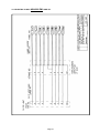
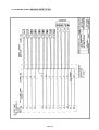
1
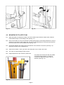
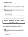
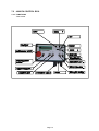
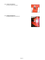
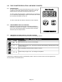
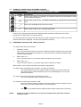
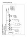
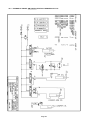
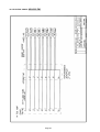
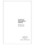
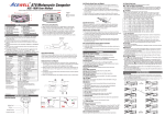
17 November 2002 4000E20.wpd USER'S MANUAL AUTO WRAP 4000 CHAP. CONTENTS PAGE 1.0 INTRODUCTION / TECHNICAL DATA 3 2.0 SAFETY PRECAUTIONS 5 3.0 SETTING UP / MOUNTING OF THE MACHINE 7 4.0 MOUNTING OF PLASTIC FILM 8 5.0 ADJUSTMENTS 9 6.0 OPERATION INSTRUCTION 10 7.0 CONTROL BOX, SENSOR 11 8.0 COUNTER 18 9.0 PERIODIC MAINTENANCE 22 10.0 CHECK POINTS BEFORE TROUBLE SHOOTING 22 11.0 TROUBLE SHOOTING 23 12.0 ELECTRIC, HYDRAULIC CIRCUIT DIAGRAM 25 13.0 SPARE PARTS LIST 33 14.0 WARRANTY TERMS WARRANTY CARD 70 71 Page 1 AUTO WRAP 4000 EH Bale Wrapping Machine 1.0 INTRODUCTION. Page 2 TELLEFSDAL A.S congratulates you with the choice of AUTO WRAP 4000 bale wrapping machine. We are certain you will be satisfied with the machine, and that you will have the pleasure of your investment for many years. This manual is meant to explain how AUTO WRAP 4000 is prepared, mounted, used and how it works, and shall together with the spare part's list be a reference for maintenance and trouble shooting. So take good care of this book, as it is a part of the machine. Read carefully through this manual, and specially chapter 2.0, safety instructions, before starting the machine, and follow the instructions thoroughly. If problems should occur, check with chapter 3,0, and try to find out what is wrong. Ask your dealer for advice before you make the problem worse than it is. See also chapter 14.0, conditions of warranty. AUTO WRAP 4000 2000 mm 2700 mm 1120 mm 2500 mm 5020 mm 31 x15.5-15 8 ply / 2,6 bar 30 km/h 1750 kg 30 rev. per minute 35 rev. per minute Ø 1500 x 1200 mm 1200 kg 1 single work. + free return Electro mechanic/Automatic control system 180 bar / 20 liters per minute 12 V DC Height in working position Height in transport position Height to the top of the rollers Width, max. Length, max. Wheel size / max. air pressure Speed, max Weight Revolution speed for the table, recommended. Revolution speed for the table, max. Bale size, max. Bale weight, max. Hydraulic connection Operated Oil pressure / amount, min. Electric connection TELLEFSDAL A.S reserves the right to alter the product and/or its technical specifications without prior notice, and without this entitling any alterations to previously supplied products. © All rights in pursuance of the Copyright Act shall apply, and any reproduction of the contents of this booklet, in whole or in part, is forbidden without the permission of TELLEFSDAL A.S. Reservation is made for possible printing errors. Page 3 2.0 SAFETY PRECAUTIONS. TELLEFSDAL A.S does not take the responsibility for damages that may occur on machine, persons or other equipment, because of the machine NOT being used as described in this manual, or because of the safety precautions NOT being followed. 2.1 SAFETY EQUIPMENT. Before using the machine, make sure that all safety equipment, is in order and securely fitted. The machine must not be operated if a function does not work as described later in this manual. (See chapter 2.5) 2.2 BECOME FAMILIAR WITH THE OPERATIONS OF THE MACHINE. If you are unsure how to operate the machine properly, either use of or maintenance to your Auto Wrap, please contact your Auto Wrap dealer. 2.3 ADJUSTMENTS' / MAINTENANCE. Turn off the tractor and discharge the oil pressure before performing any adjustment or maintenance on the machine. Remember that a well maintained machine is a safe machine. 2.4 IMPORTANT! MAKE ALWAYS SURE THAT NOBODY IS IN THE HAZARD AREA (5 METRES DISTANCE) OF THE WRAPPING MACHINE WHEN THE MACHINE IS IN USE. THE MACHINE MUST NEVER BE OPERATED BY PERSONS WHO DO NOT KNOW ENOUGH ABOUT HOW TO SAFELY OPERATE THE MACHINE, OR BY CHILDREN UNDER 16 YEARS OF AGE. Page 4 Fig. 2-2 2.5 Fig. 2-3 DANGEROUS AREAS. TELLEFSDAL A.S has given the safety to the operator the highest priority, but it is still impossible to secure oneself of every danger area on the machine. Therefore we will now go through some of the dangers that can occur when using the Auto Wrap bale wrapper. 1. PUNCH OF THE TURN TABLE. During the wrapping process the turn table rotates with a speed of 20-30 revolutions per minute, and can give a person serious injuries, if too close to the working area of the wrapping machine. 2. SQUEEZE-DANGER BETWEEN THE MAIN FRAME AND THE TURN TABLE. Every time the corners of the turn table pass the main frame, there is a squeeze danger to any person standing too close. When the bale is finished wrapped and tipped off the machine, the table must be tipped down before the next bale may be wrapped. When the middle-frame with the turn table is lowered there is a danger of being squeezed on both sides of the machine as well as behind. Keep fingers, hands and feet well out of the way. (Fig. 2-2) 3. SQUEEZE DANGER CAUSED BY THE PLASTIC WRAPPING AUTOMATION. At the end of the wrapping process the plastic shall be perforated and held tight until the start of the next wrapping process. When the cutter cylinder moves to lock the plastic, there can occur a squeeze danger between the cutter cylinder and the cutter holder. The cutter blade that cuts of the plastic is very sharp, so keep hands away from the cutter. (See fig. 2-3). 4. SQUEEZE DANGER CAUSED BY THE LOADING ARM. When lifting and lowering the loading arm, squeeze danger might occur between the loading arm and the main frame or the ground. Under maintenance or parking/storing the loading arm must be lowered to the ground or secured with the locking bolt in raised position. Page 5 2.6 TIPPING OFF THE BALE. Be careful when tipping off the bales, so that they can not cause damage to persons or equipment. 2.7 DURING WRAPPING During the wrapping proses the operator should keep his hands on the control box. The machine should stand horizontally when wrapping. Take care so that nobody gets into the machines working area. 2.8 2.9 TRANSPORTING. When transported on a public road there are certain safety measures that must be taken: 1. Make sure that the loading arm is in a raised position and locked. 2. Make sure that the machine do not cover the tractors lights. If necessary, mount extra lights. DISENGAGING Before disengaging the machine from the tractor, the operator must make sure that the parking foot is lowered and locked. Page 6 3.0 SETTING UP / MOUNTING OF THE MACHINE Be careful! There is a danger of being crushed when working implements are fitted and connected. Carry out the fitting procedures slowly and carefully, and use separate and approved lifting equipment to make the work easier. See section 3 on safety regulations and pay attention to the various safety details displayed on different parts of the bale wrapper. 3.1 Mount the draw bar. The draw bar may be adjusted vertically. When connecting to the tractor the machine must be as horizontal as possible. To adjust remove the nuts and bolts, move up of down. 3.2 Mount the loading arm and adjust the width on the loader in accordance with the bales diameter. Adjust the loading arms end stopper so that the bale will be placed in the middle of the table when loading. 3.3 Mount the fall demper. 3.4 Place the pre-stretcher in the pre-stretcher holder / cylinder. To achieve a good wrapping result it is necessary for the plastic to meet with the center of the bale. The arm the pre-stretcher is fasted too, may be lowered up or down in a holder which has several holes. Remove nuts and bolts, adjust, reinsert nuts and bolts. 3.5 Mount the supporting rollers on the table. 3.6 lubricate the machine. 3.7 Check that all the bolts and nuts are tightened, specially the wheel bolts. 3.8 Remove the safety bolts used under transportation from the loading arm and turn table, insert the safety bolts into the parking holes. 3.9 Connect the machine to the tractors rear trailer hitch. 3.10 Connecting the hydraulics. The hydraulic hoses between the machine and the tractor are equipped with 1/2" ISO male couplings. Dump the oil pressure before the to and from coupling of the hydraulic hoses. Use the tractors hydraulic lever. If the bale wrapper is to function correctly, the tractors oil pressure must be a minimum of 180 bar. The oil amount should be 20 - 25 litters per minute. The counter pressure on the return has to be as low as possible, and is not to exceed 10 bar. This should be checked with a manometer. It is recommended to use a single action hydraulic outlet and arrange a “free return” directly to the tank. If you are unsure as to which oil pressure the tractor has, or which pressure the bale wrapper may receive, contact your machine supplier. All tractors will in general have some counter pressure in the hydraulic return system. Some tractors have more than others. Hoses with red labeling connect to the pressure, (P) and hoses with blue labeling connect to the return, (T). 3.11 Place the control box in the tractor cabin. 3.12 Lift the parking foot. 3.13 Test all the functions, before the first bale is loaded on to the wrapper. 3.14 NEVER DRIVE THE TIP UP IF THE TURN TABLE IS IN LOADING POSITION!!!! The result can be expensive, the center axle can bend. This damage will not be covered by the warranty Page 7 Fig. 4-1 Fig. 4-2 4.0 MOUNTING OF PLASTIC FILM. 4.1 When the plastic roll shall be mounted, you have to hold the pre-stretcher-rollers aside, Hold the rollers aside and put on the holding hook. (See fig. 4-1). 4.2 Place a reel of film on to the pre-stretcher's holding axle and put on the spring loaded lock. The pre stretcher is mounted to fit the 750mm film, but may be adjusted easily by moving the top bracket to the lower holes so as to fit the 500mm film. (See fig. 4-3) 4.3 Pull the film between the rollers on the pre-stretcher in the direction of the arrow. (See fig. 4-2). (See also the sign on the wrapping arm). 4.4 Open the film holder / cutter, pull out the film and place it in the cutter, then close. 4.5 The cutter is closed holding the film in place. 4.6 Height adjustment of pre-stretcher / plastic film. The plastic film should meet with the middle of the bale being wrapped, so it may be necessary to adjust the height of the pre stretcher. (See fig. 4-4) Fig. 4-3 Page 8 Fig. 5-1 4000EH Fig. 5-2 4000EM 5.0 ADJUSTMENTS. 5.1 HEIGHT ADJUSTMENT OF THE PRE-STRETCHER. See4.3 5.2 CONTROL BOX FUNCTIONS. See chapter 7. 5.3 REVOLUTION SPEED OF TURNTABLE. The speed of the turntable is adjusted by the speed of the tractor engine and the throttle valve for the turn table speed, pos A (See fig. 5-1 and 5-2). Adjust this until the turntable speed is approx. 27 revolutions per minute (approx. 2,2 seconds per revolution). The revers speed, on the EM machine is adjusted with the valve pos. B. (See fig. 5-2). The machine can also be equipped with a control valve that makes it easier to adjust the speed. Then you can have full opening of the lever and adjust the oil-flow to the machine, and by that adjust the speed of the turntable. This valve is extra equipment. 5.5 OVERLAP. To control the overlap, stop the machine after a few turns. Use a marker to mark a line on the middle of the film wrapped on the bale. By the next turn this line should just be covered. The AUTO WRAP 4000 is for use with the 750mm and 500mm film. The machine is delivered for use with the 750mm film, when using 500mm film the chain wheels on the rollers must be changed. Fig. 4-4 Page 9 6.0 OPERATING INSTRUCTIONS. 6.1 6.2 6.3 We will here give a complete description for the wrapping process, from loading to storage, and explain the practical use of the AUTO WRAP 4000 EM with manuel control and AUTO WRAP 4000 EH with data control.Before use the transport bar on the loading arm must be removed. Lower the loading arm. Remember that the plastic film must be locked in place by the cutter, before wrapping can begin. The table must also (if necessary) be rotated, allowing the rollers to stand parallel to the machine. (Speed direction) LOADING. Drive to the side of the bale so that the forks on the loading arm, are stationed on either side of the bale. Drive all the way forward so that the bale is stopped against the end stopper of the loading arm. the loading arm is then carefully lifted high enough for the bale to tip onto the table. Make sure that there is nobody or any thing on the opposite side of the machine before tipping. Lower the loading arm again. START. AUTO WRAP 4000 EM has a slow start so as to protect the film at the moment of starting. When the table has rotated a couple of times, the plastic end must be released. This is done by pulling on the cutter lever until the blades are open. HOW MANY LAYERS OF PLASTIC?. With the AUTO WRAP 4000 EM. When the wrapping of the first bale starts, one counts the rotations on the table. When the bale is completely covered with plastic, multiply the number of rotations done in accordance to the figures below: * * 4 layers of plastic - multiplied by 2 6 layers of plastic - multiplied by 3 If the AUTO WRAP 4000 EM is equipped with a counter, the number of rotations is programmed in and an alarm will be given when the bale is finished. See chapter 8 about the counter. With the AUTO WRAP 4000 EH the settings and counting is steered with the control box, chap 7 6.4 STOP With the AUTO WRAP 4000 EM, take care so that the table is in the correct position in relation to the fall damper before the off loading, tipping of the bale is started. If the table has rotated to much, it may be reversed by pushing the wrapping lever gently away from you until the table is in the correct position. NEVER DRIVE THE TIP UP IF THE TURN TABLE IS IN LOADING POSITION!!!! The result can be expensive. The center axle can bend. This damage will not be covered by the warranty. The table on the AUTO WRAP 4000 EM may now be tipped. The table must be tipped manually until the plastic laying inn the cutter, the plastic will be cut. The tip-cylinder and the fall damper cylinder are connected, so that when the table is raised the fall damper will simultaneously rise so that the two meet. When the table has risen all the way up, the bale tips over on to the fall damper. When the table is lowered again, the fall damper is also lowered in a slow and careful manner and the bale rolls off. With the AUTO WRAP 4000 EH the functions are steered automatically (See chap 7) CHECK THAT NOBODY OR ANYTHING IS ON THE OPPOSITE SIDE OF THE MACHINE DURING THE PROSES OF OFF LOADING!! 9.5 STORAGE In the storage area the bales should be systematically placed. Try not to come in contact with the other bales with the equipment. Place the bales as close together as possible to keep the plastic ends tight, it is recommended to check and if necessary tighten the loose plastic ends manually, on each separate bale. 9.6 TRANSPORTING. When travelling over long distances and on public roads the machine must be secured for transport 1. 2. The loading arm is raised to it´s highest position and made safe. The turn table is secured. Page 10 Fig. 7-1 Control box 4000 EM 3. 4. Fig. 7-2 Control box 4000 EH The fall demper is secured on models with the side tip. Detach the hydraulic hoses belonging to the tractor. 7.0 CONTROL BOX, SENSORS. 7.1 4000 EM CONTROL BOX FUNCTIONS. 7.1-1 TOP JOYSTICK : Up = TABLE TIP DOWN Left = REVERS Right = START Down = TABLE TIP UP 7.1-1 BOTTOM JOYSTICK : Up = LOADING ARM DOWN Left = CUTTER DOWN Right = CUTTER UP Down = LOADING ARM UP 7.1-3 EMERGENCY STOP Page 11 The emergency stop arm stops the wrapping sequence instantly, and cuts out all the power supply to the machine. The emergency stop is cancelled by turning the switch to the right. Page 12 7.2 4000 EH CONTROL BOX. 7.2-1 FUNCTIONS Table model. Page 13 7.2-2 OPERATOR MENU Auto-wrap Controlbox 2000 AW 4000/404 16 mars 2000 JH Notice: By pressing "EXIT" more than 3 sek. You allways will be braught back to "Wrap-cycle" ( Wrapp modus) By pressing "MENU" more than 3 sek, the display contrast will be adjusted. "MENY" up = Stronger MENY down = weaker Manual operation Behind the rubberplug on the the rear side of the control box it is placed a switch for manual/automatic operation. Please notice that the display does`nt work in manuel modus. Display nbr ( ) Wrap cycle: 0-10 Balecounter 1: Programing nbr laps/bale MENU Adjust flashing numbers SET: Change SET: Nextl EXIT: Store EXIT: Store EXIT: Store 3. Programing 2 Reset Counters MENU Reset SET: Enter Setup EXIT: Store 3 SET: Change MENU Version 4 404 EH (with loading arm 404 700 EH ( Without loadingarm) ( Without loadingarm) MENU 4000 EH ( With loadingarm) Press SET to change settings 5 6 7 8 9 10 11 12 13 14 15 16 17 18 19 20 21 22 23 EXIT Store Auto load bale with load arm Raise load arm above sensor duration Load arm, up to down delay Lower load arm, on sensor duration Wait for startsignal after load 4000 700 404 Yes NO 5.0 8,,5 0.0 0.0 0.1 Yes 0.1 Yes 2.0 2.0 2.0 2.0 1.5 2.0 6.0 0.0 1.5 6.0 0.0 1.5 5.0 0.5 1.5 0.2 Yes 0.2 Yes 0.0 Yes 3.6 3.6 1.3 2.0 2.3 2.0 2.3 2.0 1.0 0.0 0.0 0.0 0.3 Yes 0.3 Yes 0.5 Yes Table Is horizontal sensor included Cutnow sensor included Yes Yes Yes No No No Rotate load position sensor included Yes Yes No No No No Rotate slow duration Revolution until fil release Realese film Rotate fast, start of final rev. Rotate slow duration Stop table duration Wait for startsignal before offload If no cutsensor:tip up, until cut Film cut duration Tip up (after cut) duration Delay, tip upp to tip down. Tip down duration Rotate after tip Sensor setup Press SET to enter 404 w/arm 1.5 2.0 5.0 0.5 1.5 MENU : Adjust flashing numbersl EXIT: Store MENU : Adjust flashing numbers EXIT: Store 0.0 Yes 1.3 2.0 1.0 0.0 0.5 Yes SET: Enter 24 25 26 27 Load arm up/down included Page 14 Yes No Yes Yes Actual RPM: (Alarm limits :28-35) Actual wrapping speed Alarm on 28 rpm Stop 35 rpm HOME 28 Balecounter SET: enter 29 Reset possible ? Yes No Yes Bales total for all 9 balecounters Bales machine total Balecounter 1: 2: 3: 30 31 32 Balecounter 4: 5: 6: 33 Balecounter 7: 8: 9: 35 36 Reset possible ? Yes No Working hours since last reset Working hours machine total SET: Enter Dänish English Nederlands Francais Deutsch SET: Adjust MENU Reset EXIT: Store MENU: Adjust flashing numbers EXIT: Store MENU: Adjust flashing numbers EXIT: Store SET: Enter 37 Audio alarm 38 Display contrast 39 Display light Hardware test. EXIT: Store Home 34 Audioalarm & Display MENU: Reset SET: Enter Working HRS: Machine tot: Language : SET: Adjust Yes Yes On 100 On EXIT: Store SET: Enter 40 Description 41 Supply voltage 42 43 44 Present voltage Last drop to Test keys pressed 000.000 Test switches aktivated 00.00.00.00.00 Relays, 0=off.AMP nbr 0--.0000.000-.-00 Last registrated drop of voltage. (Test 6 programbuttons) (Test av 5 stk funktion switches) ( Test relayoutputs. AMP sprocket 1-16 ) Nbr 10,11,12.13,14,15,16 are indicated with A,B,C,D,E,F,G SET: A signal change the displayed out/in put from 0 into 1. 45 Sensor (input) TEST Press SET to enter SET: Enter 46 Rotate (load) 47 Rotate tip Loadingarm down Cut/horizontal 48 Infra red Rec.Input Nr 1 Nr 2 Nr 3 Nr 15 Sensor test countersignal Sensor test tip Sensor test loadarm Sensor test table horizontal 1 = Yes 1 = Yes 1 = Yes 1 = Yes Sensor test Infra red input 1 = Yes 0 = No Page 15 0= No 0= No 0 = No 0 = No SET: A signal change the displayed out/in put from 0 into 1. 4. Wrappingcycle Aktivited sensors a. Loading Loadarm down Loadarm rais and return back on sensor Table in loadposition Table is hold in loadposition b. Wrapping Start: Starts up on 1/2 speed and runs further in 1/1 speed Table down Loadarm down Wrapping Wrap with adjusted speed unntil setted nbr of revolutions. Unload position Stop. Table goes to stop from 1/1 to 1/2 speed an stops on sensor. c. Unloading Table starts raising Table stops and the cutter is closing Table goes further to the top and return to sensor frame. Loadarm down Loadposition Table turns into loading position JH 16 feb.2000 Page 16 7.3 SENSOR 7.3-1 INSTALLING THE SENSOR AND MAGNET The magnet must be mounted on the rotating element, e. g. the table of the wrapper. The sensor must be installed on a bracket, securing that the magnet passes the sensor end within a distance Please notice: of 2 - 8 If the sensor is to be mounted on a mounting mm. bracket which is magnetizable (iron), then the See the sensor must be placed at least 5 mm beyond drawing the edge of the mounting bracket. below: Please take notice, so that the cable from the sensor will be protected and not break when the tractor is turning, or when the hydraulic is used. 7.3-2 MAGNET PLACED ON THE CENTRE AXEL. On the EM model there is 1 magnet as shown in the picture, on the EH model there are 2. 7.3-3 SENSOR PLACING. The upper sensor steers the loading operation. The lower sensor steers the off-loading 7.3-4 TABLE SENSOR WITH MAGNET. Page 17 7.3-4 LOADING ARM SENSOR. The sensor is placed on the frame. 7.3-4 LOADING ARM MAGNET. The magnet is placed on the loading arm. Page 18 8.0 FLEX COUNTER REVOLUTION AND WRAP COUNTER 8.1 INTRODUCTION The flex counter is an instrument with many functions. The unit consists of a box with a display and two control keys. Both the display and the control keys are large and easy to use. The flex counter has six functions,. Which function one choses to use, is selected by depressing the keys on the control box as with the revolutions and bales count (F.6). The flex counter will hear after be referred to as the computer. 8.2 PROGRAMMING THE FLEX COUNTER. Right below, the programming rules of the Flex Counter are described. Furthermore, the chapter “ The individual functions” gives a more thorough description of the 6 functions and their attached input and output factors. 8.3 CHANGING THE FUNCTIONS OF THE FLEX COUNTER. Changing from one function to another is done in the following manner: Key Display Example : Changing function. Explanation F. 1 The current function is found on the display. F. 1 Press the key for app. 2 sec - the function number starts flashing, indicating that its value may be changed. F. 6 Push repeatedly until the function number is correct. F. 6 Press the key for app. 2 sec - the change is completed. Furthermore, programming-mode is automatically exited, if the Flex Counter does not receive signals from the keys within a 10 second interval. Page 19 8.4 CHANGING AND RESETTING VALUES. As previously mentioned in the introduction, the computer has six functions. The table below shows these functions. The relationship between functions and input-/output factors. No. Function Factors Speed indicator Reset or Change Speed Display symbol _._._._ Wheel circumferen. Area I Area II Wheel circumferen. Working width Units Counting factor Rev. pr. minute RPM-hours Working hours Wrap counter Wrap number Bales I Bales II o HA. 1 HA. 2 o |----| cou. cou.F r. --:---:-PULLS PULLS bale.1 bale.2 C R R C C R C Limits 0,0 - 999,9 km/t F. 1 F. 2 Area counter F. 3 Unit counter F. 4 Revolution counter F. 5 F. 6 Working hours Wrap counter R R R C R R 00,00 - 999,9 cm 0,000 - 9999 ha 0,000 - 9999 ha 00,01 - 999,9 cm 00,01 - 99,99 m 0,001 - 9999 pcs. 0,001 - 9,999 pcs. 0012 - 9999 rpm 00:00 - 9999 hours 00:00 - 9999 hours 0 - 99 rev. 2 - 99 rev. 0 - 9999 bales 0 - 9999 bales When the computer is used with the AUTO WRAP 4000, the most interesting function will be F.6 The table shows, which values may be changed and which may only be reset. Values that may be changed are indicated by a C. Values that may only be reset are indicated by an R. If values are to be changed, the function containing the specific value must first be entered. Please refer to the table above. 8.5 EXAMPLE ON SETTING THE NUMBER OF ROTATIONS PER BALE. Remember to set the computer on the correct function (F.6.) Cross ref. with 8.3 Key Example: changing the revolution per bale from 12 til 31. Display Explanation 0:12 Press until Pulls is shown on the display. The display shows after a short time the number of revolutions the computer is set too 12 The key is pressed for app. 2 sec. The number - 1- will flash in the display and the value may be changed. 32 Press Several times until the value of the first digit is correct. 32 The second digit flashes indicating that its value may be changed. 31 .Press Several times until the value of the second digit is correct. 0:31 The key is pressed for app. 2 sec. programming is complete. Further more, programming-mode is automatically exited, if the Flex Counter does not receive signals from the keys within a 10 second interval. Page 20 8.6 EXAMPLE ON RESETTING THE NUMBER OF BALES. Remember to set the computer on the correct function (F.6.) Key Display 120 Example on resetting the number of bales Explanation Press the key until bale.1 is displayed. The display shows after a short period the number of bales which are wrapped. _120 Press the key for app. 2 sec. - the display starts flashing, indicating that its value may be reset. ___0 Press ones, the display shows a line and a zero. Press the key for app. 2 sec., leaving programming. 0 Further more, programming-mode is automatically exited, if the Flex Counter does not receive signals from the keys within a 10 second interval. The same procedure is used for both bale counters, except for that in the first row the key must be pressed until bale.2 is displayed. The rest of the operation is identical. 8.7 DESCRIBING THE FUNCTION “WRAP COUNTER” The wrap counter has three functions. 1. Revolution counter This is a function that monitors the number of rotations the table has taken at any given time. With the help of a sensor and a magnet. The required number of rotations desired per bale may be pre-programmed. 2. Bale counter no. 1. This is a function which e.g. counts the number of bales per job or per day. 3. Bale counter no. 2. This is a function which e.g. counts the total number of bales for a season. Bale counters 1 and 2 may be used when and where it is appropriate. The wrap counter is equipped with one alarm. The alarm is activated: * One rotation before the pre-set required number of rotations is reached. When the next pulse signal is received the alarm stops, but is activated again, if one or more pulses are received. The values of the bale counters are increased by one when: * The pre-set required number of rotations is reached. The revolution counter (wrap counter) is reset: * When the required number of rotations has been reached, and the computer does not receive any more pulse signals within a 10 seconds period. * NOTE! The -key is pressed while the display shows the wrap number (PULLS function). If there are to many rotations on one bale, the set-key must be pressed to reset the revolution count. Page 21 8.8 TURNING THE FLEX COUNTER ON AND OFF-STOP-MODE. In order to lower the power consumption of the Flex Counter, and there by increasing the life time of the batteries, the computer may be sat in stop-mode. The display will then be turned off and the computer is paused until a new signal is received from the sensor or a pressed key. The computer may be sat in stop-mode manually. This is done by pressing the -key for app. 5 seconds. The display shows “stop” until key is realised, now the display is turned off. If the computer, within 30-90 min. has not received any pulse or key-press signals, the computer is automatically sat in stop-mode. 8.9 POWER SUPPLY. LOW : LB The computer must be supplied with power from two 1,5V AA-batteries. When the computer is re-started having been in stop-mode, the display first shows the version number of the specific computer. The computer then checks the power level, if this is low the display shows -bL-. if the display fades out, the batteries must be changed. If during use, the power supply from the batteries dwindles the computer will occasionally flash the -bL- message. The batteries must then be changed, as counting errors may occur. If display-problems occur after battery replacement, wait for two minutes and then reinstall the batteries. If there is still a problem check that the batteries have a power level of minimum 3V. 8.10 NOTE ! Storing data - the memory of the Flex Counter. The computer is supplied with a memory facility, that remembers the values of the input and output factors. The values of the input factors are automatically stored when they are changed. The value of the output factors are stored once every hour and when the computer is automatically or manually sat in stop-mode. When changing the batteries, the computer must first be manually sat in stop-mode (please refer to the Turning the Flex Counter on and off-stop-mode) Then the batteries may be changed without the risk of loosing data. 8.11 Specification of limits. Pulse signals from the sensor: max. 167 pulse signals per second. min. pulse time: 0,6ms~the magnet must activate the sensor for 1/10 of the time at 9999 rpm. Temperature limits: The Flex Counter is fully operational within -10 to 70 °C. This does not necessarily apply for the batteries, please check with your local battery dealer. Clock: +/- 0,5%. Has influence on the accuracy of the following functions: speed (km/h), rpm and working hours. Page 22 9.0 PERIODIC MAINTENANCE. 9.1 BEARINGS. The ball-bearings in the centre of the table are greased and do not need further maintenance. All other parts that are in motion should be lubricated once a day. 9.2 ANGULAR GEAR The bevel gear drive in the turn table’s centre, (below the cover lock) must also be greased when required. 9.3 CHAINS. The chains must be oiled from time to time. Once a year they should be taken out so as they may be cleaned and greased. soak the chains in oil for 2-3 days then hang them up to drip off. After a time with constant use the chain from the motor, which drives the turn table will need to be re-adjusted. This is done by loosening 4 bolts on the motor bracket and then tightening the adjusting bolt. DO NOT TIGHTEN TOO MUCH, AS THIS WILL ENFORCE THE WEAR ON THE BEARINGS AND CHAINS. 9.4 CLEANING. The machine should be cleaned and oiled regularly and at the end of the wrapping season. NOTE ! When using high pressure washing apparatus, care must be taken with the electrical installation. Also make sure that water is not sprayed directly into the bearings, etc.. Keep the counter box protected from rain and water. 9.5 HYDRAULIC CYLINDERS. Make sure that all hydraulic cylinders are closed when storing the machine. 9.6 QUICK COUPLERS. Take care in keeping the quick couplers clean and apply the dust caps after use. 9.7 STORAGE. The machine should be parked on a dry place during the closed season. 10.0 CHECK POINTS BEFORE TROUBLE SHOOTING. In this chapter we have some general check points that have to be examined first if something is wrong with the machine. In chapter 11.0 we have a more detailed trouble shooting. There are two basic assumptions that have to be fulfilled if the machine shall function properly: 1. 2. 3. The oil pressure from tractor should be 180 bar. The return flow of oil has to be as free as possible, max. 10 bar counter pressure. 12 Volt directly from the battery. 10.1 OIL PRESSURE. Control the oil pressure to the machine with a manometer, apply on the oil pressure hose, for example on the quick coupler.If the pressure is less than 180 bar, there will be less power for the functions. The first place you trace this is at the LOADING OF THE BALE. OIL AMOUNT. The oil amount that the tractor delivers must be minimum 20 litres/minute, (Max. allowed oil amount is 25 litres/minute). REMEMBER! Large oil amount = Valves get hot. (Small oil tank = insufficient cooling). 10.2 COUNTER PRESSURE. MAX. ALLOWED COUNTER PRESSURE IS 10 BAR. If you are in doubt about the counter pressure, arrange a "free return" directly to the tank. PLEASE CONTACT YOUR DEALER IF YOU ARE IN DOUBT OF ANYTHING. Page 23 (Remember always to give your dealer the serial number and production year of your machine when contacting dealer and when ordering spare parts). 11.0 TROUBLE SHOOTING. BEWARE OF MOVING PARTS WHEN TESTING THE MACHINE. 11.1 THE MACHINE DOES NOT WORK. a) The gauge shows that there is enough pressure but there is no reaction from the machine. The problem can be that one or both of the quick couplers are not opening to let the oil through. Change the quick couplers. b) The counter pressure may be to high. Max. counter pressure is 10 bar (Operating disorders of this kind, acker usually during the first few days that the machine is in use) 11.2 RETURN OFF KNIFE CYLINDER. PRESSURE SETTING THE ACCUMULATOR 1 Drive the knife cylinder to closed possession. 2 Remove plug from the diverter valve behind the accumulator. 3 Connect hose from + knife cylinder on the diverter valve. 4 Open the knife with knife close function.(low pressure) 5 Connect hose back to knife cylinder. 6 Test the knife. 7 If the knife don’t close, let out oil pressure on the return side of the knife cylinder until the knife is closed. 8 If the knife dos not open, the pressure on return side its to low 11.3 THE KNIFE WILL NOT HOLD THE PLASTIC FILM. Check the pressure in the accumulator , return . 11.4 THE TABLE WILL NOT ROTATE. a) The safety valve on the motor, may be leaking, so that the oil passes the motor. Disengage the valve and check that the piston moves freely. b) Check if the oil motor is working. Ask your dealer for advice BEFORE you make the error larger and more difficult to repair. Page 24 There are 3 basics which must ALWAYS be followed if the machine is to function correctly. Page 25 12.0 HYDRAULIC, ELECTRIC CHART 12.1 HYDRAULIC CHART AW 4000 EM ELECTRIC MANUEL. Page 26 12.2 HYDRAULIC CHART AW 4000 EM SIDE TIP ELECTRIC MANUEL. Page 27 12.3 HYDRAULIC CHART AW 4000 EH STD FALL DEMPER AUTO. EL. Page 28 12.3 HYDRAULIC CHART AW 4000 EH SIDE TIP AUTO. EL. Page 29 12.4 ELECTRIC CHART AW 4000 EM. Page 30 12.5 ELECTRIC CHART AW 4000 EM. SIDE TIP. Page 31 12.6 ELECTRIC CHART AW 4000 EH. Page 32 12.7 ELECTRIC CHART AW 4000 SIDE TIP EH. Page 33 14.0 WARRANTY TERMS. 14.1 TELLEFSDAL A.S. warrantees the AUTO WRAP 4000 bale wrapping machine for 12 full months from the date of purchase. 14.2 During the warranty period TELLEFSDAL A.S will repair, replace or test any parts proved to be defective in material or construction. 14.3 Before comprehensive warranty services are done, the warranty claim has to be agreed upon with TELLEFSDAL A.S. By approval of warranty claims TELLEFSDAL A.S covers all repair costs. Freight costs and all personal travel costs are normally the responsibility of the dealer. Before repairing the machine locally the terms of compensation have to be agreed upon between the buyer and the manufacturer. Compensation for defective parts corresponds to the current spare parts price-list, minus normal discount. If the warranty claim should be rejected, TELLEFSDAL A.S is not responsible for expenses incurred. 14.4 All claims must be presented in written form, on a fixed NOTICE OF CLAIM, and enclosed a copy of the warranty card, properly filled in. Guarantee claimed parts also have to be enclosed. All return shall be agreed upon before sending, and marked with serial number on the machine and the name and address of the dealer. Freight costs for returned parts have to be payed by the buyer. 14.5 The NORSE warrantee is NOT valid if: a) The warrantee card has not been filled out and a copy is not enclosed with the claim. b) The user's manual and safety instructions have not been followed. c) The machine has been misused, abused or carelessly operated. d) The machine is modified by welding or by attachments of not original parts and pieces. It has been serviced by persons, who are unauthorized by Tellefsdal A.S. 14.6 TELLEFSDAL A.S IS NOT responsible for lost working time or lost revenue that has resulted because of a defect in the machine. 14.7 The buyer can not claim a cancellation the purchase, a price-reduction or any other claims, if TELLEFSDAL A.S, within reasonable time, repairs the machine. 14.8 The buyer is granted credit on warranty claims AFTER approval from TELLEFSDAL A.S. Deductions of credits on current invoices is not accepted without prior agreement. Page 70 WARRANTY CARD AUTO WRAP Serial number of machine: Type: Serial number of control unit: Production year: Purchase date: WE HAVE READ AND ACCEPT THE CURRENT WARRANTY TERMS. Importer: Date Firm Signature Date Firm Signature Dealer: Customer: Name Address Signature HAVE YOU GOT ENOUGH TRAINING ABOUT THE MACHINE FROM YOUR DEALER? Page 71 YES NO