1
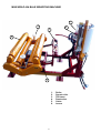
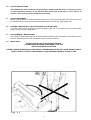
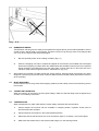
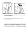
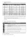
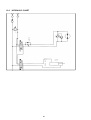
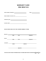
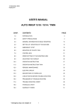
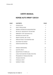
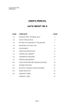
18 December 2002 404B99E.WPD USER'S MANUAL NORSE MINI WRAP 404 CHAP. CONTENTS PAGE 1.0 INTRODUCTION 2 2.0 SAFETY PRECAUTIONS 3 3.0 GENERAL INFORMATION ON BALE WRAPPING 4.0 SETTING UP / MOUNTING OF THE MACHINE 6 5.0 MOUNTING OF PLASTIC FILM 7 6.0 ADJUSTMENTS / USE 8 7.0 OPERATION INSTRUCTION 8 8.0 FLEX COUNTER 10 9.0 PERIODIC MAINTENANCE 14 4 10.0 CHECK POINTS BEFORE TROUBLESHOOTING 11.0 TROUBLE SHOOTING 15 12.0 HYDRAULIC CHART 16 13.0 SPARE PARTS LIST 19 14.0 WARRANTY TERMS 26 WARRANTY CARD 27 1 15 MINI WRAP 404 BALE WRAPPING MACHINE 6 2 4 5 1 3 1. 2. 3. 4. 5. 6. 2 Roller Suport roller Tilt frame Prestrecher Cutter Levers 1.0 INTRODUCTION. TELLEFSDAL A.S congratulates you with the choice of MINI WRAP bale wrapping machine. We are certain you will be satisfied with the machine, and that you will have the pleasure of your investment for many years. MINI WRAP 404 is hydraulically driven by the tractors hydraulic system, and is easy to operate with the hydraulic levers. The MINI WRAP 404 is designed to be a simple and effective bale wrapping machine square bales. MINI WRAP 404 is estimated for wrapping bales of grass, hey or straw, it can handle bales from 35cm x 45cm up to 50cm x 50cm. The bales must have a weight of at least 35kg. This manual is meant to explain how MINI WRAP is prepared, mounted, used and how it works, and shall together with the spare part's list be a reference for maintenance and troubleshooting. So take good care of the books, they are a part of the machine. Read carefully through this manual, and specially chapter 2.0, safety instructions, before starting the machine, and follow the instructions thoroughly. If problems should occur, please contact your MINI WRAP dealer. Ask your dealer for advice before you make the problem worse than it is. See also chapter 13.0, Warranty terms. Technical Specifications MINI WRAP 404 Height in working position Width Length Weight Turntable speed, recom. Turntable speed, max. Bale size, max. Bale weight, min. Prestretcher Hydraulic connection Oil pressure / amount, min. Oil amount, max. Counter pressure, max. 1370 mm 1080 mm 19800 mm 360 kg 22 rev. per minute 27 rev. per minute 500 x 500 x 1150 mm 35 kg 500 mm 1 sing.work.outlet,+free return 100 bar / 15 liter per minute 30 liter per minute 10 bar TELLEFSDAL A.S can change the construction and/or technical specifications without warning and without rights to changes on already delivered products. © Copyright. All rights reserved. Any copying and reproduction of this manual is not permitted without permission from TELLEFSDAL A.S. With precaution of printing failure. 3 2.0 SAFETY PRECAUTIONS. TELLEFSDAL A.S does not take the responsibility for damages that may occur on machine, persons or other equipment, because of the machine NOT being used as described in this manual, or because of the safety precautions NOT being followed. 2.1 SAFETY EQUIPMENT. Before using the machine, make sure that all guards and covers are securely fitted. The machine must not be operated if a function does not work as described later in this manual. (See chapter 2.5). 2.2 BECOME FAMILIAR WITH THE OPERATIONS OF THE MACHINE. If you are unsure how to operate the machine properly, either use of or maintenance to your Mini Wrap, please contact your Mini Wrap dealer. 2.3 ADJUSTMENTS' / MAINTENANCE. Turn off the tractor and discharge the oil pressure before performing any adjustment or maintenance on the machine. Remember that a well-maintained machine is a safe machine. 2.4 IMPORTANT! MAKE ALWAYS SURE THAT NOBODY IS INSIDE THE MACHINE'S WORKING AREA WHEN IT'S IN USE. SAFETY DISTANCE IS 5 METRES THE MACHINE MUST NEVER BE OPERATED BY PERSONS WHOM DOES NOT KNOW ENOUGH ABOUT HOW TO SAFELY OPERATE THE MACHINE, OR BY PERSONS UNDER 16 YEARS OF AGE. Fig. 2-1 4 Fig. 2-2 2.5 DANGEROUS AREAS. TELLEFSDAL A.S has given the safety to the operator the highest priority, but it is still impossible to secure oneself of every danger area on the machine. Therefore we will now go through some of the dangers that can occur when using the Mini Wrap balewrapper. 1. Become specially aware of the rotating turntable. (Fig 2-1) 2. When the wrapping of a bale is complete and tipped off the machine, the turntable has to be tipped back before wrapping next bale. When the middle frame with turntable is lowered, there is a squeeze danger between the middle frame and the main frame on both sides and in the back end of the machine. Keep therefor fingers and feet in safe distance. (Fig. 2-2). 3. When tipping the turntable, the bale will roll free off the machine. Staying behind the machine can cause danger for "overrunning" by the bale when it rolls off. Make therefor sure that nobody is behind the machine when unloading. 2.6 WHILE WRAPPING. Let the machine rest on the ground while wrapping. Make sure that nobody comes into the working area of the machine. 2.7 THREE POINT MOUNTING. When the machine is mounted in the three point linkage, make sure that the lifting arms are tightened up so there is no sideways movement. 2.9 TRANSPORTING. When transported on a public road there are certain safety measures that must be taken: 1. Always tranport the machine with the turntable in transport position. Hydraulic hoses must be disconnected under transport. 2. Always transport the machine in the lowest possible position. 3. Make sure that the machine does not cover the tractors' lights. If necessary, mount extra lights. 4. Make sure that at least 20% of the tractor's total weight is on the steering wheels. 5 3.0 GENERAL INFORMATION ON BALE WRAPPING. 3.1 THE PRINCIPLE. The advantages of round bale ensilage are many, and include fewer feed units, a flexible harvesting system, large capacity and the possibility of selling feed units. In principle, the same fermentation processes occur whether the fodder is placed in a silo or pressed into bales and packed in plastic, i.e. lactic acid fermentation in anaerobic conditions. The oxygen in the bale must be exhausted before fermentation begins. The grass should be dried to approximately 30-40% solid content. The solid content can be determined by twisting the grass by hand. If drops of liquid are forced out of the grass, the solid content is less than 25%. Low solid content, (wet grass), can lead to increased butyric acid fermentation if preservatives are not added to the grass. If the solid content is too high, (over 50%), normal fermentation will not take place and there will be enough oxygen in the bale to produce mould fungus. 3.2 THE BALER. It is vital that the baler produces compact, well-formed bales, as misshapen bales can be difficult to wrap. Baling will also often take longer, thereby increasing the amount of plastic used. 3.3 TYPES OF PLASTIC. A good type of plastic with good adhesive properties, and which is recommended for bale wrapping, must be used. The thickness of the plastic foil should be at least 25 µ. (25/1,000 mm). In order that the plastic tightens sufficiently around the bale, it is stretched before being wrapped, so it is somewhat thinner when it is put on the bale. With short-term storage, (up to eight weeks), it is recommended that bales have a minimum of four layers of plastic at the thinnest points, with at least 52-53% overlap. For long-term storage, or when the grass is wet when it is wrapped, the bale should have 90-100 µ plastic, (6 layers), and the same amount of overlap. If thinner plastic is used, more layers should be applied. If it is very hot the plastic will be stretched further, and more layers should be applied. It is better to have slightly too much than too little plastic on the bale. From experience, light plastic produces slightly lower temperatures within the bale, and tends to improve feed quality. 3.4 STORAGE LOCATION. Care should be taken in finding a suitable location for the storage of bales. The storage location should preferably be prepared before the bales are laid out. An elevation close to well-drained roads is recommended. If the wrapped bales are simply placed on stubble there is a danger of the plastic being pierced. A tarpaulin or a thin layer of sand should therefore be laid where the bales are to be stored over the winter. Bales should be stored in the shade as far as possible. This reduces the danger of air leakage in the bales. A bale which is stored in sunlight and which therefore undergoes greater swings in temperature "pumps in" a great deal of air in comparison to a bale which is stored in the shade. According to "Teknik for Lantbruket" [Technology for Agriculture] in Sweden, a bale which is stored in the shade has only 40% of the air leakage of a bale which is stored in sunlight. 3.5 STACKING / PROTECTION. If bales are hard and well formed, they can be stacked vertically, but loose and misshapen bales with low solid content should not be stacked higher than one layer, as this could easily cause deformity and the danger of runoff will be increased. Bales can also be stored on their sides. The layer of plastic is thicker here, providing greater protection against piercing. Bales should be covered with a tarpaulin or a fine-mesh net to protect against birds and small rodents. If the plastic is pierced, it must be sealed with weatherproof, hard-wearing tape, preferably under the outermost layer of plastic. Ensure that the hole is adequately sealed. 3.6 The best wrapping results are obtained by... 6 1. ...harvesting the grass early. 2. ...drying it out to 30-40% solid content. If there is a danger of rain, bale and wrap the grass anyway. 3. ...taking care not to mix any earth in with the grass. 4. ...using a baler which produces even, firm bales. 5. ...wrapping the bales soon after baling, never later than two hours afterwards. 6. ...using a good type of plastic and six layers of plastic. This removes the need to use preservatives. 7. ...storing bales in the shade to reduce the danger of air leakage. 7 4.0 SETTING UP / MOUNTING OF THE MACHINE. 4.1 Due to transport the prestretcher may not be mounted when delivered. THE PRESTRETCHER is to be mounted on the right side of the machine. It is adjustable different heights after the size of the bales. 4.2 THREE POINT LINKAGE. MINI WRAP 404 is intended for rear mounting to the three point linkage, category 2. When attached to three point linkage, make sure the machine is level across the tractor. Tight up and lock the lifting arms so there is no sideways movement. 4.3 TOP LINK. Adjust the top link of the tractor so that the machine is level with the ground. 4.4 HYDRAULIC CONNECTION. The hydraulic hoses between machine and tractor are equipped with 1/2" ISO male quick-couplers. Discharge the oil pressure before you connect the oil hoses. Use the tractors' hydraulic lever. Connect the hoses so that the turntable rotates counterclockwise. To make sure that the balewrapper works properly, the tractors' oil pressure has to be at least 100 bar. If you are unsure of what oil pressure the tractor gives, or what oil pressure the balewrapper receives, please contact your machinery dealer. When connected to a tractor with closed centre (ex. JOHN DEERE) the central duct of the valve must be plugged. NB! 4.5 ELECTRIC CONNECTION. The counter-unit for MINI WRAP 404 is powered batteries inside the box. These batteries have to be checked regularly. Remove event. corrosion that prevents good contact. Change the batteries if necessary. Remember to store the counter-unit on a dry place. There is a quick-coupler on the cable between the switch and the counter, so it is easy to connect and disconnect. 4.6 CHECK LIST. Before using the machine it is recommended to follow this check list: 1. Make it a habit to discharge the oil-pressure before connection or disconnection of the hydraulic hoses. (Use the tractors hydraulic control lever). 2. Hose with BLUE CAP = RETURN OIL. 3. Hose with RED CAP = PRESSURE. 4. Tie up loose hoses so that no squeeze damages occur. 5. Start the tractor and try out the functions. (It shall rotate counterclockwise). 6. Check all connections, hoses and couplings. If there is any oil-leakage, it should be rectified immediately. Your MINI WRAP bale wrapper has been tested in practical operation in approx. 2 hours at the factory. 8 5.0 MOUNTING OF PLASTIC FILM. Fig. 5-1 Fig. 5-2 5.1 When the plastic roll shall be mounted, you have to hold the prestretcher-rollers aside, Hold the rollers aside and put on the holding hook. (See fig. 5-1). 5.2 Place a reel of film on to the prestretcher's holding axle and put on the springloaded lock. 5.3 Pull the film between the rollers on the prestretcher in the direction of the arrow. (See fig. 5-2). (See also the sign on the prestretcher). 5.4 Pull out the film and tie it to the bale. 5.5 HEIGHT ADJUSTMENT OF PRESTRETCHER / PLASTIC FILM. The plastic film shall hit at the middle of the bale wrapped, and therefore it can be necessary to adjust the height of the prestretcher. The prestretcher can be placed in different positions. Disconnect the locking bolt, and adjust the prestretcher so that the plastic hits in the middle of the bale. Replace the locking bolt and the splint. If you use 250 mm plastic on a 500 mm prestrecher, then you can use the two distance sleeves to adjust the height on the plastic roll. There can be mounted one sleeve on each side of the plastic roll, or both sleeves can be mounted above or below. (see also 6.5 Overlap) 9 6.0 ADJUSTMENT / OPERATING. 6.1 SUPPORT ROLLERS. Place the bale you want to wrap on top of the rollers. Move the support rollers as tight to the bale as possible. Make sure that the bale is in centre of the rollers. 6.2 HEIGHT ADJUSTMENT OF PRESTRETCHER. The prestretcher can be placed in different positions. Disconnect the locking bolt, and adjust the prestretcher so that the plastic hits in the middle of the bale. Replace the locking bolt and the splint. 6.4 REVOLUTION SPEED OF TURNTABLE. Start the machine by operating the lever inside the tractor. The speed of the turntable is adjusted by the speed of the tractor engine or how much you move the lever. Adjust this until the turntable speed is approx. 22 revolutions per minute (Just below three seconds per revolution). The machine can also be equipped with a control valve that makes it easier to adjust the speed. Then you can have full opening of the lever and adjust the oil-flow to the machine, and by that adjust the speed of the turntable. This valve is extra equipment. 6.4 OVERLAP. To control the overlap, stop the machine after a few turns. Use a marker to mark a line on the middle of the film wrapped on the bale. By the next turn this line should just be covered. It is now possible to use ether the 500mm or the 250mm film on the MINI WRAP 404. The machine is prepared for use with the 500mm film, when using 250mm film the chains from the turntables main shaft must be lengthened with the enclosed chain pieces and moved to the largest chain wheels. 10 7.0 OPERATION INSTRUCTION. We shall now go through a complete wrapping process, from loading to storage place, and explain the practical use of MINI WRAP 404. 7.1 LOADING. Loading a bale on this machine has to be done externaly. The machine cannot load the bales on itself. Place the bale on top of the rollers, as close to the middle as possible. Move both support rollers as close to the bale as possible. 7.2 HEIGHT ADJUSTMENT OF PRESTRETCHER. The height of the prestretcher has to be adjusted so that the plastic film is always hitting the middle of the bale. (See more about this in chapter 5.5.) 7.3 TIPS ON WRAPPING SQUARE BALES. The MINI WRAP 404 has on deliverance the rollers inn the middle position. If the bales to be wrapped are inn some degree larger or smaller than middle measure then the rollers must be moved. (Optimally the film should meet the bale being wrapped in the middle.) The chain cover must be removed, and the square-unit moved either inn or out. The chain is adjusted, then the chain-tension is tightened before finely the bolts are replaced Remember that a hard and well pressed bale wil give the best result when packing. 7.4 START. Remember that the plastic film end must be tied to the bale. This is normally only necessary on the first bale. Operate the hydraulic lever carefully to make a gently start. To quick a start can rip off the plastic film, and then it has to be tied again. IMPORTANT ! This function will hold the lever in rotation position until the lever is pushed back inn neutral. 7.5 OVERLAP. Control that the overlap is correct. If not, see chapter 6.5. 7.6 HOW MANY LAYERS OF PLASTIC FILM? To obtain the required amount of film on the bale, follow the steps below: 1. Start packing and count the number of rotations. When the bale is completely covered with film, multiply this number with either 2 or 3, depending on how many layers the bale is to be covered with. * 4 layers - multiply by 2. * 6 layers - multiply by 3. As long as the bales being packed have the same diameter, the packing proses may be stopped on the same number each time. 2. Start packing whilst watching the time. When the bale is completely covered with film, multiply the seconds which has past, with 2or 3, depending on how many layers the bale is to be covered with. 3. If the machine is equipped with a counter follow the procedure inn point 1. 7.7 STOP / UNLOADING. When the wrapping is complete, stop the machine when the rollers stand crosswise, the tractor. If the turn table passes the position, it must be returned and will then automatically stop in the right position for off loading. Then lift the turntable until the bale falls off with the lever marked for this function. The film can be left sticking too the bale, because this is preferred cut off when loading the next bale. 7.8 NEW BALE. Lower the turntable down again. Then place a new bale on top of the rollers, (upon the plastic film from last bale), and start wrapping. Now the plastic film from the last bale should be cut off. Fasten the film end, if necessary, with some weatherproof tape. 11 8.0 FLEX COUNTER REVOLUTION COUNTER AND WRAP COUNTER 8.1 Introduction The flex counter is an instrument with many functions. The unit consists of a box with a display and two control keys. Both the display and the control keys are large and easy to use. The flex counter has six functions,. Which function one choses to use, is selected by depressing the keys on the control box. We will concentrate for the most part on the operations which register the revolutions and bales count (F.6). The flex counter will hear after be referred to as the computer. 8.2 Programming the Flex Counter. Below, the programming rules of the Flex Counter are described. A more detailed description of the functions and their attached input and out put factors, follow throughout this chapter. 8.3 Changing the functions of the Flex Counter. Changing from one function to another is done in the following manner: Key Display F. 1 Example : Changing function. Explanation The current function is found on the display. F. 1 Press the key for app. 2 sec - the function number starts flashing, indicating that its value may be changed. F. 6 Push repeatedly until the function number is correct. F. 6 Press the key for app. 2 sec - the change is completed. Furthermore, programming-mode is automatically exited, if the Flex Counter does not receive signals from the keys within a 10 second interval. 12 8.4 Changing and resetting values. As previously mentioned in the introduction, the computer has six functions. The table below shows these functions. No. The relationship between functions and input-/output factors. Function Factors Display Reset or Limits symbol Change Speed indicator Speed _._._._ 0,0 - 999,9 km/t F. 1 F. 2 Area counter F. 3 Unit counter F. 4 Revolution counter F. 5 F. 6 Working hours Wrap counter Wheel circumferen. Area I Area II Wheel circumferen. Working width Units Counting factor Rev. pr. minute RPM-hours Working hours Wrap counter Wrap number Bales I Bales II o HA. 1 HA. 2 o |----| cou. cou.F r. --:---:-PULLS PULLS bale.1 bale.2 C R R C C R C R R R C R R 00,00 - 999,9 cm 0,000 - 9999 ha 0,000 - 9999 ha 00,01 - 999,9 cm 00,01 - 99,99 m 0,001 - 9999 pcs. 0,001 - 9,999 pcs. 0012 - 9999 rpm 00:00 - 9999 hours 00:00 - 9999 hours 0 - 99 rev. 2 - 99 rev. 0 - 9999 bales 0 - 9999 bales If the computer is used with the Auto Wrap 4000M, the F.6 will be the most interesting function. The table shows, which values may be changed and which may only be reset. Values that may be changed are indicated by a C. Values that may only be reset are indicated by an R If values are to be changed, the function containing the specific value must first be entered. Please refer to the table above. 8.5 Example on setting the number of rotations per bale. Remember to set the computer on the correct function (F.6.) Key Display 0:12 Example: changing the revolution per bale from 12 til 31. Explanation Press until Pulls is shown on the display. The display shows after a short time the number of revolutions the computer is set too 12 The key is pressed for app. 2 sec. The number - 1- will flash in the display and the value may be changed. 32 Press Several times until the value of the first digit is correct. 32 The second digit flashes indicating that its value may be changed. 31 .Press Several times until the value of the second digit is correct. 0:31 The key is pressed for app. 2 sec. programming is complete. Further more, programming-mode is automatically exited, if the Flex Counter does not receive signals from the keys within a 10 second interval. 8.6 Example on Resetting the number of bales. 13 Remember to set the computer on the correct function (F.6.) Key Display 120 Example on resetting the number of bales Explanation Press the key until bale.1 is displayed. The display shows after a short period the number of bales which are wrapped. _120 Press the key for app. 2 sec. - the display starts flashing, indicating that its value may be reset. ___0 Press ones, the display shows a line and a zero. 0 Press the key for app. 2 sec., leaving programming. Further more, programming-mode is automatically exited, if the Flex Counter does not receive signals from the keys within a 10 second interval. The same procedure is used for both bale counters, except for that in the first row the key must be pressed until bale.2 is displayed. The rest of the operation is identical. 8.7 Describing the function “Wrap counter” The wrap counter is constructed to be used with machinery that wrap, both round- and square bales in folio. The wrap counter has three functions. 1. Revolution counter This is a function that monitors the number of rotations the table has taken at any given time. With the help of a sensor and a magnet. The required number of rotations desired per bale may be pre programed. 2. Bale counter no. 1. This is a function which e.g. counts the number of bales per job or per day. 3. Bale counter no. 2. This is a function which e.g. counts the total number of bales for a season. Bale counters 1 and 2 may be used when and where it is appropriate. The wrap counter is equipped with one alarm. The alarm is activated: * One rotation before the pre-set required number of rotations is reached. When the next pulse signal is received the alarm stops, but is activated again, if one or more pulses are received. The values of the bale counters are increased by one when: * The pre-set required number of rotations is reached. The revolution counter (wrap counter) is reset: * When the required number of rotations has been reached, and the computer does not receive any more pulse signals within a 10 seconds period. * NOTE! The -key is pressed while the display shows the wrap number (PULLS function). If there are to many rotations on one bale, the set-key must be pressed to reset the revolution count. 14 8.8 Turning the Flex Counter on and off-stop-mode. In order to lower the power consumption of the Flex Counter, and there by increasing the life time of the batteries, the computer may be sat in stop-mode. The display will then be turned off and the computer is paused until a new signal is received from the sensor or a pressed key. The computer may be sat in stop-mode manually. This is done by pressing the The display shows “stop” until key is realised, now the display is turned off. -key for app. 4 seconds. If the computer, within 30-90 min. has not received any pulse or key-pres signals, the computer is automatically sat in stop-mode. 8.9 Power supply. The computer must be supplied with power from two 1,5V AA-batteries. When the computer is re-started having been in stop-mode, the display first shows the version number of the specific computer. The computer then checks the power level, if this is low the display shows -bL-. if the display fades out, the batteries must be changed. If during use, the power supply from the batteries dwindles the computer will occasionally flash the -bL- message. The batteries must then be changed, as counting errors may occur. If display-problems occur after battery replacement, wait for two minutes and then reinstall the batteries. If there is still a problem check that the batteries have a power level of minimum 3V. 8.9 Storing data - the memory of the Flex Counter. The computer is supplied with a memory facility, that remembers the values of the input and output factors. The values of the input factors are automatically stored when they are changed. The value of the output factors are stored once every hour and when the computer is automatically or manually sat in stop-mode. When changing the batteries, the computer must first be manually sat in stop-mode (please refer to the Turning the Flex Counter on and off-stop-mode) Then the batteries may be changed without the risk of loosing data. 8.10 Specification of limits. Pulse signals from the sensor: max. 167 pulse signals per second. min. pulse time: 0,6ms~the magnet must activate the sensor for 1/10 of the time at 9999 rpm. Temperature limits: The Flex Counter is fully operational within -10 to 70 °C. This does not necessarily apply for the batteries, please check with your local battery dealer. Clock: +/- 0,5%. Has influence on the accuracy of the following functions: speed (km/h), rpm and working hours. 15 8.11 INSTALLING THE SENSOR AND MAGNET The magnet must be mounted on the rotating element, e. g. the table of the wrapper. The sensor must be installed on a bracket, securing that the magnet passes the sensor end within a distance of 2 - 8 mm. See the drawing below: Please notice the following: If the sensor is to be mounted on a mounting bracket which is magnetizable (iron), then the sensor must be placed at least 5 mm beyond the edge of the mounting bracket. Please take care, so that the cable from the sensor is protected so it may not break when the tractor is turning, or when the hydraulic is used. 16 9.0 PERIODIC MAINTENANCE. 9.1 BEARINGS. All ball-bearings are packed with grease, and do not need any more maintenance. 9.2 PRESTRETCHER. If the machine is in daily use, the guiding sleeves at the prestretcher should be oiled once a week or when needed. Sprockets and bearings on the prestretcher should also be oiled when needed. 9.3 CHAINS. Oil the chains at regular intervals. Take them off once a year for cleaning and oiling. Soak the chains in oil for 2-3 days and afterwards hang up for 10-12 hours to drain. After some use, the chain from the motor to the turntable has to be adjusted. Unlock the nuts on the motor bracket, and tighten up the adjustment. DO NOT TIGHT TOO MUCH, CAUSE THIS WILL INCREASE THE WEARING OF THE BEARINGS. The chains on the square rollers also have to be adjusted. There is one tensioner on each side. 9.4 GEAR. The shaft in the turn table´s senter (below the cover) must be greased when required. 9.5 HYDRAULIC CYLINDERS. (Only for RC-models). Make sure that the hydraulic cylinder is closed when storing the machine. 9.6 CLEANING. The machine should be cleaned and oiled regularly and by the end of the wrapping season. NB! When using a steamer, you need to be careful with the electric equipment and bearings. Keep the counter protected from rain or water. 9.7 QUICK COUPLERS. Be painstaking by keeping the quick couplers clean and apply the dust caps after use. The conecting hoses are to be placed in the holders, on the side of the machine when not in use. 9.8 STORAGE. The machine should be parked on a dry place during the closed season. 17 10.0 CHECK POINTS BEFORE TROUBLE SHOOTING. In this chapter we have some general check points that have to be examined first if something is wrong with the machine. In chapter 11.0 we have a more detailed trouble shooting. There are two basic assumptions that have to be fulfilled if the machine shall function properly: 1. 2. 10.1 The oil pressure from tractor should be 180 bar. The return flow of oil has to be as free as possible, max. 10 bar counter pressure. OIL PRESSURE. In order to control that the oil pressure into the machine is high enough, there has to be applied a gauge to the oil pressure hose, for example on the quick coupler. If the pressure is less than 180 bar, there will be less power for the functions. OIL AMOUNT. The oil amount that the tractor delivers must be minimum 15 litres/minute, (Max. allowed oil amount is 25 litres/minute). REMEMBER! Large oil amount = Valves get hot. (Small oil tank = insufficient cooling). 10.2 COUNTER PRESSURE. The counter pressure can be too high. With high counter pressure the machine's functions will get less power. High counter pressure means also that you need more power to operate the valves. MAX. ALLOWED COUNTER PRESSURE IS 10 BAR. If you are in doubt about the counter pressure, arrange a "free return" directly to the tank. PLEASE CONTACT YOUR DEALER IF YOU ARE IN DOUBT OF ANYTHING. (Remember always to give your dealer the serial number and production year of your machine when contacting dealer and when ordering spare parts). 18 11.0 TROUBLE SHOOTING. BEWARE OF MOVING PARTS WHEN TESTING THE MACHINE. 11.1 11.2 The machine does not work. a) The gage shows that there is enough pressure but there is no reaction from the machine. The problem can be that one or both of the quick couplers are not opening to let the oil through. Change the quick couplers. b) The counter pressure may be to high. Max. counter pressure is 10 bar The table will not rotate. a) b) The safety valve on the motor, may be leaking, so that the oil passes the motor. Disengage the valve and check that the piston moves freely. Check if the oil motor is working. Ask your dealer for advice BEFORE you make the error larger and more difficult to repair. 11.3 Return off knife cylinder. Pressure setting the accumulator. A.Drive the knife cylinder to closed position. B.Remove plug from the diverter valve behind the accumulator. C.Connect hose from + knife cylinder on the diverter valve. D.Open the knife with knife close function. (low pressure) E.Connect hose back to knife cylinder F.Test the knife. G.If the knife don`t close, let out oil pressure on the return side of the knife cylinder until the knife is closed H.Ifthe knife dos not open, the pressure on return side its to low. 11.4 The knife will not hold the plastic film. Check the pressure in the accumulator, see chapter 11.3 19 12.0 HYDRAULIC CHART 20 14.0 WARRANTY TERMS. 14.1 TELLEFSDAL A.S. warrantees the NORSE MINI WRAP 404 bale wrapping machine for 12 full months from the date of purchase. 14.2 During the warranty period TELLEFSDAL A.S will repair, replace or test any parts proved to be defective in material or construction. 14.3 Before comprehensive warranty services are done, the warranty claim has to be agreed upon with TELLEFSDAL A.S. By approval of warranty claims TELLEFSDAL A.S covers all repair costs. Freight costs and all personal travel costs are normally the responsibility of the dealer. Before repairing the machine locally the terms of compensation have to be agreed upon between the buyer and the manufacturer. Compensation for defective parts corresponds to the current spare parts price-list, minus normal discount. If the warranty claim should be rejected, TELLEFSDAL A.S is not responsible for expenses incurred. 14.4 All claims must be presented in written form, on a fixed NOTICE OF CLAIM, and enclosed a copy of the warranty card, properly filled in. Guarantee claimed parts also have to be enclosed. All return shall be agreed upon before sending, and marked with serial number on the machine and the name and address of the dealer. Freight costs for returned parts have to be payed by the buyer. 14.5 The NORSE warrantee is NOT valid if: a) The warrantee card has not been filled out and a copy is not enclosed with the claim. b) The user's manual and safety instructions have not been followed. c) The machine has been misused, abused or carelessly operated. d) The machine is modified by welding or by attachments of not original parts and pieces. It has been serviced by persons, who are unauthorized by Tellefsdal A.S. 14.6 TELLEFSDAL A.S IS NOT responsible for lost working time or lost revenue that has resulted because of a defect in the machine. 14.7 The buyer can not claim a cancellation the purchase, a price-reduction or any other claims, if TELLEFSDAL A.S, within reasonable time, repairs the machine. 14.8 The buyer is granted credit on warranty claims AFTER approval from TELLEFSDAL A.S. Deductions of credits on current invoices is not accepted without prior agreement. 36 WARRANTY CARD MINI WRAP 404 Serial number of machine: Type: Serial number of control unit: Production year: Purchase date: WE HAVE READ AND ACCEPT THE CURRENT WARRANTY TERMS. Importer: Date Firm Signature Date Firm Signature Dealer: Customer: Name Address Signature HAVE YOU GOT ENOUGH TRAINING ABOUT THE MACHINE FROM YOUR DEALER? 37 YES NO