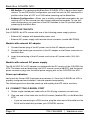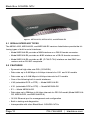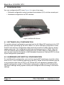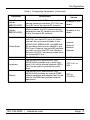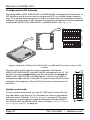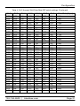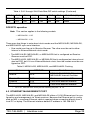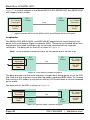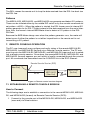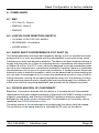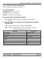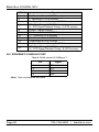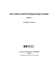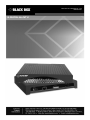
1
ME231A-R2, ME232A-R2, and
ME233A-R2
G.SHDSL.bis NTU
Black Box G.SHDSL NTU
TABLE OF CONTENTS
1.
1.1
1.2
1.3
1.4
2.
2.1
2.2
2.3
2.4
About this guide .................................................................................. 6
Audience ............................................................................................... 6
Structure................................................................................................ 6
Precautions ........................................................................................... 7
Safety when working with electricity...................................................... 8
General observations ............................................................................ 9
Quick Start ........................................................................................... 9
Select Configuration Method ................................................................. 9
Power up the NTU............................................................................... 10
Models with external AC adapter ........................................................ 10
Models with external DC power supply ............................................... 10
Power up indication ............................................................................. 10
Connect the G.SHDSL port ................................................................. 10
Connect the serial port ........................................................................ 11
3.
3.1
3.2
3.3
ME231A-R2, ME232A-R2, and ME233A-R2 overview ..................... 11
Serial interface types........................................................................... 12
Features .............................................................................................. 12
Power input connector......................................................................... 13
External AC universal power supply.................................................... 13
4.
4.1
4.2
Configuration..................................................................................... 14
Software (CLI) configuration................................................................ 14
Hardware (DIP-switch) configuration................................................... 14
Configuring the DIP switches .............................................................. 18
System reset mode ............................................................................. 18
DIP switch settings .............................................................................. 19
S4-2 through S4-8: Data Rate............................................................. 20
DCE/DTE operation............................................................................. 23
Ethernet Management Port ................................................................. 23
Help Commands.................................................................................. 26
System Configuration Commands....................................................... 27
System Status Commands.................................................................. 27
DSL Configuration Commands............................................................ 27
DSL Status Command......................................................................... 28
DSL Clear Errcntrs Command............................................................. 28
E1 Configuration Commands .............................................................. 28
E1 Status Commands ......................................................................... 28
Remote Console.................................................................................. 28
Example Command Line Interface Session ........................................ 29
4.3
4.4
Page 2
724-746-5500 | blackbox.com
5.
5.1
5.2
5.3
5.4
5.5
5.6
6.
6.1
6.2
6.3
Installation ......................................................................................... 30
Connecting the twisted pair interface .................................................. 31
Connecting the Model ME231A-R2, ME232A-R2, and ME233A-R2
serial interface..................................................................................... 32
Connecting the Model ME231A-R2, ME232A-R2, and ME233A-R2
to a “DCE” or “DTE” device ................................................................. 32
Connecting the Model ME231A-R2 serial interface ............................ 33
Connecting the Model ME231A-R2 to an E1 Network ........................ 33
Connect twisted pair (120 ohm) to E1 network ................................... 33
Connecting dual coaxial cable (75 ohm) to E1 network ...................... 34
Connecting power ............................................................................... 35
Operation ........................................................................................... 35
Power-up............................................................................................. 35
LED status monitors............................................................................ 36
Power (Green) .................................................................................... 36
DSL (Green)........................................................................................ 36
Link (Green) (Model ME231A-R2) ...................................................... 36
Terminal (Green)................................................................................. 37
TM/ER (Yellow) ................................................................................... 37
LOS (Red) [Model ME231A-R2].......................................................... 37
Link (Green) ........................................................................................ 37
Activity (Green) ................................................................................... 37
Test modes ......................................................................................... 37
Loopbacks........................................................................................... 38
Patterns............................................................................................... 39
7.
7.1
Remote Console Operation.............................................................. 39
Establishing a Remote Console Session ............................................ 39
How to Connect .................................................................................. 39
How to Disconnect .............................................................................. 41
Differences in Local and Remote Control Session Behavior .............. 41
8.
Software upgrade.............................................................................. 42
9.
Reset Configuration to factory defaults.......................................... 42
A.
A.1
A.2
A.3
A.4
Compliance........................................................................................ 43
EMC .................................................................................................... 43
Low Voltage Directive (Safety) ........................................................... 43
Radio and TV Interference (FCC Part 15) .......................................... 43
CE Declaration of Conformity ............................................................. 43
724-746-5500 | blackbox.com
Page 3
Black Box G.SHDSL NTU
B.
B.7
B.8
B.9
B.10
B.11
B.12
B.13
B.14
B.15
B.16
Black Box G.SHDSL NTU ME231A-R2. ME232A-R2,
ME233A-R2 Specifications ............................................................... 44
Clocking modes................................................................................... 44
DTE rate ............................................................................................. 44
Serial interface ................................................................................... 44
Serial connector ................................................................................. 44
Diagnostics ......................................................................................... 44
Status LEDs ....................................................................................... 44
Power (Green)..................................................................................... 44
DSL (Green) ........................................................................................ 44
Link (Green) (E1 only) ......................................................................... 45
Terminal (Green) ................................................................................. 45
TM/ER (Yellow) ................................................................................... 45
LOS (Red) [ME231A-R2]..................................................................... 45
Link (Green) ........................................................................................ 45
Activity (Green).................................................................................... 45
Configuration ...................................................................................... 45
Power and power supply specifications ............................................. 46
External AC universal power supply ................................................... 46
Transmission line ............................................................................... 46
Line coding ......................................................................................... 46
Line rates (DSL line) ........................................................................... 46
Line interface ...................................................................................... 46
G.SHDSL physical connection ........................................................... 47
Environment ....................................................................................... 47
Third party software licenses .............................................................. 47
C.
Factory default values for software-configurable parameters ..... 47
D.
D.1
D.2
D.3
D.4
D.5
Interface Pin-outs.............................................................................. 48
Line port .............................................................................................. 48
V.35 interface ..................................................................................... 49
E1 interface ........................................................................................ 49
X.21 interface ..................................................................................... 49
Ethernet Console port ........................................................................ 50
B.1
B.2
B.3
B.4
B.5
B.6
Page 4
724-746-5500 | blackbox.com
RADIO FREQUENCY INTERFERENCE STATEMENTS
FEDERAL COMMUNICATIONS COMMISSION AND INDUSTRY CANADA RADIO
FREQUENCY INTERFERENCE STATEMENTS
This equipment generates, uses, and can radiate radio-frequency energy, and if not
installed and used properly, that is, in strict accordance with the manufacturer’s instructions, may cause interference to radio communication. It has been tested and found to
comply with the limits for a Class A computing device in accordance with the specifications in Subpart B of Part 15 of FCC rules, which are designed to provide reasonable
protection against such interference when the equipment is operated in a commercial
environment. Operation of this equipment in a residential area is likely to cause interference, in which case the user at his own expense will be required to take whatever
measures may be necessary to correct the interference.
Changes or modifications not expressly approved by the party responsible for compliance could void the user’s authority to operate the equipment.
This digital apparatus does not exceed the Class A limits for radio noise emission from
digital apparatus set out in the Radio Interference Regulation of Industry Canada.
Le présent appareil numérique n’émet pas de bruits radioélectriques dépassant les
limites applicables aux appareils numériques de la classe A prescrites dans le
Règlement sur le brouillage radioélectrique publié par Industrie Canada.
724-746-5500 | blackbox.com
Page 5
Black Box G.SHDSL NTU
1. ABOUT THIS GUIDE
This guide describes installing and operating the Black Box G.SHDSL NTU Model
ME231A-R2, ME232A-R2, and ME233A-R2 G.SHDSL NTU.
1.1 AUDIENCE
This guide is intended for the following users:
• Operators
• Installers
• Maintenance technicians
1.2 STRUCTURE
This guide contains the following chapters and appendices:
• “Quick Start” on page 9 provides a brief guide to starting up the device and its
basic features and capabilities
• “Ethernet Management Port” on page 23 contains an overview describing the
device’s operations and applications
• “Configuration” on page 14 provides hardware and software configuration procedures
• “Installation” on page 30 describes how to install the device
• “Operation” on page 35 describes how to install and operate the device
• “Remote Console Operation” on page 39 describes how to operate the device
remotely
• “Software upgrade” on page 42 provides information how to upgrade the device’s
software
• “Reset Configuration to factory defaults” on page 42 provides information on how
to configure the device to its original state
• Appendix A. on page 43 contains compliance information
• Appendix B. on page 44 contains specifications
• Appendix C. on page 47 provides the factory default values
• Appendix D. on page 48 describes the device’s ports and pin-outs
For best results, read the contents of this guide before you install the device.
Page 6
724-746-5500 | blackbox.com
About this guide
1.3 PRECAUTIONS
Notes, cautions, and warnings, which have the following meanings, are used throughout this guide to help you become aware of potential problems. Warnings are intended
to prevent safety hazards that could result in personal injury. Cautions are intended to
prevent situations that could result in property damage or impaired functioning.
Note A note presents additional information or interesting sidelights.
WARNING
The shock hazard symbol and WARNING heading indicate a
potential electric shock hazard. Strictly follow the warning
instructions to avoid injury caused by electric shock.
The alert symbol and WARNING heading indicate a potential
safety hazard. Strictly follow the warning instructions to avoid
personal injury.
WARNING
The shock hazard symbol and CAUTION heading indicate a potential
electric shock hazard. Strictly follow the instructions to avoid property
damage caused by electric shock.
CAUTION
The alert symbol and CAUTION heading indicate a potential hazard.
Strictly follow the instructions to avoid property damage.
CAUTION
724-746-5500 | blackbox.com
Page 7
Black Box G.SHDSL NTU
Safety when working with electricity
•
Do not open the device when the power cord is connected. For
systems without a power switch and without an external power
adapter, line voltages are present within the device when the
power cord is connected.
•
For devices with an external power adapter, the power adapter
shall be a listed limited Power Source The mains outlet that is
utilized to power the device shall be within 10 feet (3 meters) of
the device, shall be easily accessible, and protected by a circuit breaker in compliance with local regulatory requirements.
•
For AC powered devices, ensure that the power cable used
meets all applicable standards for the country in which it is to
be installed.
•
For AC powered devices which have 3 conductor power plugs
(L1, L2 & GND or Hot, Neutral & Safety/Protective Ground), the
wall outlet (or socket) must have an earth ground.
•
For DC powered devices, ensure that the interconnecting
cables are rated for proper voltage, current, anticipated temperature, flammability, and mechanical serviceability.
WARNING
• WAN, LAN & PSTN ports (connections) may have hazardous
voltages present regardless of whether the device is powered
ON or OFF. PSTN relates to interfaces such as telephone lines,
FXS, FXO, DSL, xDSL, T1, E1, ISDN, Voice, etc. These are
known as “hazardous network voltages” and to avoid electric
shock use caution when working near these ports. When disconnecting cables for these ports, detach the far end connection first.
•
Do not work on the device or connect or disconnect cables
during periods of lightning activity.
This device contains no user serviceable parts. This device can
only be repaired by qualified service personnel.
WARNING
WARNING
Page 8
This device is NOT intended nor approved for connection to the
PSTN. It is intended only for connection to customer premise
equipment.
724-746-5500 | blackbox.com
Quick Start
In accordance with the requirements of council directive 2002/96/EC
on Waste of Electrical and Electronic Equipment (WEEE), ensure that
at end-of-life you separate this product from other waste and scrap and
deliver to the WEEE collection system in your country for recycling.
Electrostatic Discharge (ESD) can damage equipment and impair electrical circuitry. It occurs when electronic printed circuit cards are improperly handled and can result in complete or intermittent failures. Do the
CAUTION following to prevent ESD:
• Always follow ESD prevention procedures when removing and
replacing cards.
•
Wear an ESD-preventive wrist strap, ensuring that it makes good
skin contact. Connect the clip to an unpainted surface of the chassis
frame to safely channel unwanted ESD voltages to ground.
•
To properly guard against ESD damage and shocks, the wrist strap
and cord must operate effectively. If no wrist strap is available,
ground yourself by touching the metal part of the chassis.
1.4 GENERAL OBSERVATIONS
• Clean the case with a soft slightly moist anti-static cloth
• Place the unit on a flat surface and ensure free air circulation
• Avoid exposing the unit to direct sunlight and other heat sources
• Protect the unit from moisture, vapors, and corrosive liquids
2. QUICK START
2.1 SELECT CONFIGURATION METHOD
Before powering up, you must select one of the following methods for configuring your
Black Box:
• Plug ‘n’ Play—The Black Box G.SHDSL NTU comes factory-configured for Plug
’n’ Play configuration when connected to a service-provider network.
724-746-5500 | blackbox.com
Page 9
Black Box G.SHDSL NTU
• DIP Switch—For deploying the Black Box G.SHDSL NTU in back-to-back applications. To use DIP-switch configuration you must first set the DIP switches to a
position other than all OFF or all ON before powering-up the Black Box.
• Software Configuration—Allows you to modify configurable parameters by connecting a PC to the console port and issuing software commands. To use software configuration you must set all the DIP switches to the ON position before
powering-up the Black Box.
2.2 POWER UP THE NTU
Your G.SHDSL.bis NTU comes with one of the following power supply options:
• External AC adapter with detachable power cord
• External DC power supply with terminal block connector (model 48V-PSM3)
Models with external AC adapter
1.
Connect female plug of the AC power cord to the AC adapter provided.
2. Connect the barrel-type connector of the AC adapter to the Power connector on
the Black Box.
3. Insert the male plug of the AC power cord into an AC power outlet (100–240
VAC).
Models with external DC power supply
The 36–60 VDC DC to DC adapter is supplied with the DC version of the G.SHDSL.bis
NTU. The black and red leads plug into a DC source (nominal 48VDC) and the barrel
power connector plugs into the barrel power supply jack on the G.SHDSL.bis NTU.
Power up indication
Verify that the Power LED illuminates and remains lit. Once the G.SHDSL.bis NTU is
properly configured and installed, it should operate transparently.
The following sections describe power-up and reading the LED status monitors.
2.3 CONNECT THE G.SHDSL PORT
1.
Obtain single-twisted-pair cable with an RJ-45 plug connector at each end.
2. Plug one end of the cable into the RJ-45 socket (labeled DSL) on the Black Box
NTU.
•
If you are connecting to a DSL service, plug the other end of the cable into the
RJ-45 wall socket that provides your G.SHDSL service.
Page 10
724-746-5500 | blackbox.com
ME231A-R2, ME232A-R2, and ME233A-R2 overview
•
If connecting to another Black Box, verify the other end of the cable is connected to the DSL port on other Black Box G.SHDSL NTU and the DSL port is
correctly configured.
3. When a DSL link is established, the front-panel DSL LED will turn on.
2.4 CONNECT THE SERIAL PORT
Your Black Box G.SHDSL NTU comes with one of the following serial WAN ports for
connection to an NTU:
• V.35 (DB-25F)—ME233A-R2
• X.21 (DB-15)—ME232A-R2
• E1 (120-Ohm RJ-48C and dual 75-Ohm BNC connectors)—ME231A-R2
Connect the serial cable to the Black Box G.SHDSL NTU serial port as follows:
1. Attach the male connector of the serial cable to the female serial connector on
the Black Box.
2. Attach the other end of the cable to the serial connector on the local serial NTU.
Note You can connect the V.35 interface to an M/34 connector using the
interface adapter.
Note You can configure the E1 interface to either recover the network clock
from the E1 line or supply the network clock for the E1 line.
3. ME231A-R2, ME232A-R2, AND ME233A-R2 OVERVIEW
The Black Box G.SHDSL NTU ME231A-R2, ME232A-R2, and ME233A-R2 provides
high speed 2-wire connectivity to ISPs, PTTs, and enterprise environments using Symmetrical High-data-rate Digital Subscriber Line (G.SHDSL) technology.
As a symmetric DSL CPE, DSL offers the same data rates in both directions over a single pair of regular twisted pair lines using TC-PAM modulation. Line connection is
made with an RJ-45 jack. Standard versions of Model ME231A-R2, ME232A-R2, and
ME233A-R2 are powered by an 100/230 VAC (Universal) supply. The CPE features
externally-accessible DIP switches, loopback diagnostics, SNMP/HTTP remote-management capabilities using Plug ‘n’ Play, as well as in-band management.
724-746-5500 | blackbox.com
Page 11
Black Box G.SHDSL NTU
Figure 1. ME231A-R2, ME232A-R2, and ME233A-R2
3.1 SERIAL INTERFACE TYPES
The ME231A-R2, ME232A-R2, and ME233A-R2 versions listed below provide the following types of built-in serial interfaces:
• Model ME233A-R2 provides a V.35 interface on a DB-25 female connector.
• Model ME232A-R2 provides an X.21 interface on a DB-15 female connector.
• Model ME231A-R2 provides an E1 (G.703/G.704) interface on dual BNC connectors and an RJ-48C receptacle.
3.2 FEATURES
• Symmetrical high data-rate DSL (G.SHDSL)
• Data rates up to 5.69 Mbps in 64-kbps intervals for X.21 and V.35 models
• Data rates up to 2.048 Mbps in 64-kbps intervals for E1 models
• One of the following built-in serial interfaces:
• V.35 (selectable DCE or DTE) — Model ME231A-R2
• X.21 (selectable DCE or DTE) — Model ME232A-R2
• E1 — Model ME233A-R2
• Data rates up to 256kbps in 64-kbps intervals for RS-232 model (Model ME231AR2, ME232A-R2, and ME233A-R2/A)
• 10/100 Ethernet port for management and configuration
• Built-in testing and diagnostics
• Interoperable with other Black Box’s G.SHDSL NTUs
Page 12
724-746-5500 | blackbox.com
ME231A-R2, ME232A-R2, and ME233A-R2 overview
• Configurable as remote (CP) units
• Configurable as central (CO) units to operate back-to-back
• Front-panel status indicators
• CE marked
3.3 POWER INPUT CONNECTOR
The NTU comes with an AC or DC power supply. (See section “Power and power supply specifications” on page 46.)
• The power connection to the CPE is a 2.5 mm barrel receptacle with the center
conductor positive (see Figure 2).
• Rated voltage: 5 VDC
Rated current: 1 A
5 VDC
Figure 2. Power connection barrel receptacle 5 VDC diagram
External AC universal power supply
For additional specifications, see section “Power and power supply specifications” on
page 46.
• Output from power supply: 5 VDC, 2 A
• Input to power supply: universal input 100–240 VAC 50/60 Hz 0.3A
CAUTION
The external AC adapter shall be a listed limited power source that
incorporates a disconnect device and shall be positioned within easy
reach of the operator. Ensure that the AC power cable meets all applicable standards for the country in which it is to be installed, and that it
is connected to a wall outlet which has earth ground.
724-746-5500 | blackbox.com
Page 13
Black Box G.SHDSL NTU
4. CONFIGURATION
You can configure the NTU (see Figure 3) in one of two ways:
• Software configuration using command line interface (CLI) via the console port
• Hardware configuration via DIP switches
Figure 3. ME232A-R2 Shown
4.1 SOFTWARE (CLI) CONFIGURATION
To use the software configuration, you must set the S4 (Rate) DIP switches to the OFF
position before powering up the NTU. When it is set for software-configuration mode,
the NTU will read any configuration data previously saved to FLASH memory during
system power-up. If no configuration data was previously saved to FLASH, then the
NTU will load the factory-default configuration from FLASH memory. After power-up,
you may use console commands or the Embedded Operations Channel (EOC) to modify the configuration parameters.
4.2 HARDWARE (DIP-SWITCH) CONFIGURATION
To use DIP-switch configuration you must first set the DIP switches to a position other
than all OFF or all ON before powering-up the NTU. When all the DIP switches are set
to any position other than all OFF or all ON the NTU will operate in hardware (DIPswitch)-configuration mode. In DIP-switch-configuration mode the NTU will read the
DIP-switch settings during system startup and configure itself according to the switch
settings.
Page 14
724-746-5500 | blackbox.com
Configuration
Once you power-up the NTU in DIP-switch mode, it will operate in DIP-switch mode
until powered down. When operating in DIP-switch mode you cannot change any configuration settings:
• Changing the DIP switch settings while the device is running requires the dsl start
command.
• If you attempt to modify the configuration by issuing console commands, the
device will not execute your commands- except for the dsl start command and
the show commands. Instead, the NTU will respond with a message indicating
the device is operating in DIP-switch-configuration mode.
• If you attempt to modify any configuration parameters via the EOC (by changing
(EOC variables), the NTU will not execute your changes.
Table 1 lists the Model ME231A-R2, ME232A-R2, and ME233A-R2’s configurable
parameters.
Table 1. Configurable Parameters
Parameter
Password
Circuit ID
DTE Loops
(model
ME233A-R2)
TX Clock
(models
Description
The password used to login to the console.
The circuit ID used to identify the unit.
The DB-25 interface can request LALs
and RDLs using its RRDL and RLAL pins.
If DTE loops are disabled, requests for
loopbacks on these pins will be ignored.
Possible
Values
1-10 characters
1-64 characters
Enabled or Disabled
Defines where (RS-232, V.35 or X.21)
serial transmit data is sampled in relation
to the TX clock: on the falling edge (normal) or the rising edge (inverted) of the TX
clock.
Normal or
Inverted
DSL Data
Rate/Timeslots
Defines the number of DSL timeslots. The
DSL data rate is calculated by the equation: data rate = DSL timeslots x 64k. This
value also defines the maximum serial/E1
data rate.
1–72
Serial/E1
Timeslots
Defines the total number of serial/E1
timeslots utilized. This value must be less
than or equal to DSL timeslots.
ME232A-R2
and ME233AR2)
3–89 (RS-232)
3–89 (V.35)
3–89 (X.21)
1–32 (E1)
724-746-5500 | blackbox.com
Page 15
Black Box G.SHDSL NTU
Table 1. Configurable Parameters (Continued)
Parameter
Timeslot
Mapping
(Model
ME231A-R2)
Description
Possible
Values
Defines E1–to–DSL timeslot mapping. By
default defined/utilized DSL timeslots are
mapped to the first n data–bearing
timeslots on the E1 line. Line type determines which timeslots are data–bearing:
E1–Unframed: 0–31
E1–Fractional: 1–31
E1–CRC: 1–31
E1–MF: 1–15,17–31
E1–CRCMF: 1–15,17–31
E1–Unframed
(Clear Channel
G.703)
Line Type
(Model
Defines the framing format of the E1 line.
ME231A-R2)
E1–Fractional
E1–CRC
E1–Multiframe
E1–CRC & Multiframe
Line Code
(Model
Selects line coding for the E1 line.
ME231A-R2)
Line Build Out
(Model
ME231A-R2)
RX Equalizer
(Model
ME231A-R2)
Page 16
Selects wave form used on the E1 line.
When enabled, this feature removes signal distortion introduced on the E1 cable.
AMI
HDB3 (E1 only)
Pulse–75
Ohm(E1)
Pulse–120 Ohm
(E1)
Enabled (select
for long–haul
link).
Disabled (select
for short–haul
link). Long haul
LBO (line buildout) is defined
by ANSI
T1.403).
724-746-5500 | blackbox.com
Configuration
Table 1. Configurable Parameters (Continued)
Parameter
Pass Framing
(Model
ME231A-R2)
Pass Alarms
(Model
ME231A-R2)
Clock Mode
Annex
Loopback
Pattern
Description
Possible
Values
When enabled, the NTU transparently
passes framing information (E1 TS0) over
the DSL link to the remote E1 network.
Enabled or Disabled.
When enabled, the NTU passes alarms
detected on one E1 network over the DSL
link to the remote E1 network.
Enabled or Disabled
Defines the clock source operation for
both DSL and serial/E1 ports as follows.
Internal: the on–board oscillator in the
ME231A-R2, ME232A-R2, and ME233AR2 provides clock for both serial/E1 and
DSL lines. External: the serial/E1interface
provides clock for the DSL line. Receive
Recover: the DSL interface provides clock
for the serial/E1 line.
The G.991.2 Annex.
The ME231A-R2, ME232A-R2, and
ME233A-R2 provides both a local loopback (LAL) and a remote loopback (RDL).
This can be used to troubleshoot problems.
The ME231A-R2, ME232A-R2, and
ME233A-R2 provides an internal PRBS
pattern generator and detector that can be
used to run BER tests without external
equipment.
724-746-5500 | blackbox.com
Internal
External
Receive
Recover
A or B
OFF, LAL, or
RDL
OFF or
511/511e
Page 17
Black Box G.SHDSL NTU
Configuring the DIP switches
The Model ME231A-R2, ME232A-R2, and ME233A-R2 is equipped with three sets of
DIP switches, which you can use to configure the NTU for a broad range of applications. This section describes switch locations and discusses the configuration options
available. The three sets of DIP switches are externally accessible from the underside
of the Model ME231A-R2, ME232A-R2, and ME233A-R2 (see Figure 4).
1
S4
ON
2
3
4
5
6
7
8
2
3
4
5
6
7
8
2
3
4
5
6
7
8
1
S3
ON
1
S1
ON
Figure 4. Underside of ME231A-R2, ME232A-R2, and ME233A-R2 showing location of DIP
switches
ON ON
1
2
3
4
The three sets of DIP switches on the underside of the Model
ME231A-R2, ME232A-R2, and ME233A-R2 are referred to as S1, S3
and S4. For basic configuration, use DIP switch S1. For testing the
ME231A-R2, ME232A-R2, and ME233A-R2, use DIP switch S3. To
configure the rate, use DIP switch S4. This figure shows the DIP switch
orientation with respect to ON and OFF positions is consistent for all
switches.
5
6
System reset mode
8
OFF
Page 18
7
To enter system reset mode, turn the S1-1 DIP switch to the ON position and power cycle the unit. For information on how to upgrade the
software, refer to Chapter “Software upgrade” on page 42. For more
information on applying factory default configuration to the ME231AR2, ME232A-R2, and ME233A-R2, refer to Chapter “Reset Configuration to factory defaults” on page 42.
724-746-5500 | blackbox.com
Configuration
DIP switch settings
You can configure the ME231A-R2, ME232A-R2, and ME233A-R2 by setting the DIP
switches to the desired positions before you power up the NTU. If the DIP switches are
set to anything other than all OFF or all ON, the NTU will operate in DIP switch configuration mode. Once the device is powered up and operating in DIP switch configuration
mode, you cannot change configuration by any method until you power it down again.
The following tables provide an overview of the NTU DIP switch functions.
Table 2. Model ME231A-R2, ME232A-R2, and ME233A-R2 Series - S1 DIP-Switch
Functions (Configuration)
Position
S1-1
Function
(ME232A-R2 & ME233A-R2
models)
Software Reset
S1-2
S1-3
Reserved
S1-4
Function
(ME231A-R2 models)
Software Reset
ON - Multiframe
OFF - Fractional/Unframed*
ON - CRC
OFF - Fractional/Unframed
Line Coding
ON - HDB3
OFF - AMI
S1-5
S1-6
DTE/DCE (CO Only)
ON - DTE
OFF - DCE
Annex
ON - Annex B
OFF - Annex A
S1-7
Timing Source (CO only)
ON - Internal
OFF - External (Network)
S1-8
DSL Mode
ON - CO
OFF - CPE
Reserved (Leave OFF)
Annex
ON - Annex B
OFF - Annex A
Timing Source
ON - Internal
OFF - External (Network)
DSL Mode
ON - CO
OFF - CPE
*. For the Fractional or Unframed setting, both S1-2 and S1-3 must be set to the
OFF position. For the Fractional setting, timeslots must be set to a value less
than 32 (a data rate set at 1984 or less on DIP switch S4). For the Unframed
setting, timeslots must be set to a value equal to 32 (the 2048 data rate on
DIP switch S4).
724-746-5500 | blackbox.com
Page 19
Black Box G.SHDSL NTU
Table 3. S3 DIP-Switch Functions
Position
S3-1
S3-2
S3-3
S3-4
S3-5
S3-6
S3-7
S3-8
Function
Reserved
511e Pattern
511 Pattern
Test Mode Remote
Test Mode Local
S4-2 through S4-8: Data Rate
Switches S4-2 through S4-8 define both the DSL line rate and the serial data rate.
Note For ME231A-R2 model, only columns S4-4 through S4-8 apply in this
table.
Also, use S4-1 to configure the Line Build Out:
OFF = 75 ohms, ON = 120 ohms.
Table 4. S4-2 through S4-8 Data Rate DIP switch settings
S4-2
S4-3
S4-4
S4-5
S4-6
S4-7
S4-8
OFF
OFF
OFF
OFF
OFF
OFF
OFF
OFF
OFF
OFF
OFF
OFF
OFF
OFF
OFF
OFF
OFF
OFF
OFF
OFF
OFF
OFF
OFF
OFF
OFF
OFF
OFF
OFF
OFF
OFF
OFF
OFF
OFF
OFF
OFF
OFF
OFF
OFF
OFF
OFF
OFF
OFF
OFF
OFF
OFF
OFF
OFF
ON
OFF
OFF
OFF
OFF
OFF
OFF
OFF
ON
ON
ON
ON
ON
ON
ON
ON
OFF
OFF
OFF
OFF
ON
ON
ON
ON
OFF
OFF
OFF
OFF
ON
ON
ON
ON
OFF
OFF
ON
ON
OFF
OFF
ON
ON
OFF
OFF
ON
ON
OFF
OFF
ON
ON
OFF
ON
OFF
ON
OFF
ON
OFF
ON
OFF
ON
OFF
ON
OFF
ON
OFF
ON
OFF
Page 20
Data Rate (kbps)
192
256
320
384
448
512
576
640
704
768
832
896
960
1024
1088
1152
724-746-5500 | blackbox.com
Configuration
Table 4. S4-2 through S4-8 Data Rate DIP switch settings (Continued)
S4-2
S4-3
S4-4
S4-5
S4-6
S4-7
S4-8
OFF
OFF
OFF
OFF
OFF
OFF
OFF
OFF
OFF
OFF
OFF
OFF
OFF
OFF
OFF
OFF
OFF
OFF
OFF
OFF
OFF
OFF
OFF
OFF
OFF
OFF
OFF
OFF
OFF
OFF
OFF
OFF
OFF
OFF
OFF
OFF
OFF
OFF
OFF
OFF
OFF
OFF
OFF
OFF
OFF
OFF
OFF
OFF
OFF
ON
ON
ON
ON
ON
ON
ON
ON
ON
ON
ON
ON
ON
ON
ON
ON
ON
ON
ON
ON
ON
ON
ON
ON
ON
ON
ON
ON
ON
ON
ON
ON
ON
ON
OFF
OFF
OFF
OFF
OFF
OFF
OFF
OFF
OFF
OFF
OFF
OFF
OFF
OFF
OFF
OFF
ON
ON
ON
OFF
OFF
OFF
OFF
OFF
OFF
OFF
ON
ON
ON
ON
ON
ON
ON
ON
OFF
OFF
OFF
OFF
OFF
OFF
OFF
OFF
ON
ON
ON
ON
ON
ON
ON
ON
OFF
OFF
OFF
OFF
OFF
OFF
ON
ON
ON
ON
OFF
OFF
OFF
OFF
ON
ON
ON
ON
OFF
OFF
OFF
OFF
ON
ON
ON
ON
OFF
OFF
OFF
OFF
ON
ON
ON
ON
OFF
OFF
OFF
OFF
ON
ON
OFF
OFF
ON
ON
OFF
OFF
ON
ON
OFF
OFF
ON
ON
OFF
OFF
ON
ON
OFF
OFF
ON
ON
OFF
OFF
ON
ON
OFF
OFF
ON
ON
OFF
OFF
ON
ON
OFF
ON
OFF
ON
OFF
ON
OFF
ON
OFF
ON
OFF
ON
OFF
ON
OFF
ON
OFF
ON
OFF
ON
OFF
ON
OFF
ON
OFF
ON
OFF
ON
OFF
ON
OFF
ON
OFF
724-746-5500 | blackbox.com
Data Rate (kbps)
1216
1280
1344
1408
1472
1536
1600
1664
1728
1792
1856
1920
1984
2048
2112
2176
2240
2304
2368
2432
2496
2560
2624
2688
2752
2816
2880
2944
3008
3072
3136
3200
3264
3328
Page 21
Black Box G.SHDSL NTU
Table 4. S4-2 through S4-8 Data Rate DIP switch settings (Continued)
S4-2
S4-3
S4-4
S4-5
S4-6
S4-7
S4-8
OFF
OFF
OFF
OFF
OFF
OFF
OFF
OFF
OFF
OFF
OFF
OFF
OFF
ON
ON
ON
ON
ON
ON
ON
ON
ON
ON
ON
ON
ON
ON
ON
ON
ON
ON
ON
ON
ON
ON
ON
ON
ON
ON
ON
ON
ON
ON
ON
ON
ON
ON
ON
OFF
OFF
OFF
OFF
OFF
OFF
OFF
OFF
OFF
OFF
OFF
OFF
OFF
OFF
OFF
OFF
OFF
OFF
OFF
OFF
OFF
OFF
ON
ON
ON
ON
ON
ON
ON
ON
ON
ON
ON
ON
ON
OFF
OFF
OFF
OFF
OFF
OFF
OFF
OFF
OFF
OFF
OFF
OFF
OFF
OFF
OFF
OFF
ON
ON
ON
ON
ON
ON
OFF
OFF
OFF
OFF
OFF
ON
ON
ON
ON
ON
ON
ON
ON
OFF
OFF
OFF
OFF
OFF
OFF
OFF
OFF
ON
ON
ON
ON
ON
ON
ON
ON
OFF
OFF
OFF
OFF
OFF
OFF
OFF
ON
ON
ON
ON
OFF
OFF
OFF
OFF
ON
ON
ON
ON
OFF
OFF
OFF
OFF
ON
ON
ON
ON
OFF
OFF
OFF
OFF
ON
ON
ON
ON
OFF
OFF
OFF
OFF
ON
ON
ON
OFF
OFF
ON
ON
OFF
OFF
ON
ON
OFF
OFF
ON
ON
OFF
OFF
ON
ON
OFF
OFF
ON
ON
OFF
OFF
ON
ON
OFF
OFF
ON
ON
OFF
OFF
ON
ON
OFF
OFF
ON
OFF
ON
OFF
ON
OFF
ON
OFF
ON
OFF
ON
OFF
ON
OFF
ON
OFF
ON
OFF
ON
OFF
ON
OFF
ON
OFF
ON
OFF
ON
OFF
ON
OFF
ON
OFF
ON
OFF
ON
Page 22
Data Rate (kbps)
3392
3456
3520
3584
3648
3712
3776
3840
3904
3968
4032
4096
4160
4224
4288
4352
4416
4480
4544
4608
4672
4736
4800
4864
4928
4992
5056
5120
5184
5248
5312
5376
5440
5504
5568
724-746-5500 | blackbox.com
Table 4. S4-2 through S4-8 Data Rate DIP switch settings (Continued)
S4-2
S4-3
S4-4
S4-5
S4-6
S4-7
S4-8
ON
ON
OFF
OFF
ON
ON
OFF
OFF
ON
ON
ON
ON
OFF
ON
Data Rate (kbps)
5632
5696
DCE/DTE operation
Note This section applies to the following models:
• ME233A-R2 - V.35
• ME232A-R2 - X.21
There are a few things to note about clock modes and the ME231A-R2, ME232A-R2,
and ME233A-R2 sync serial interface.
• One model must be set to Receive-Recover. The other must be set to either
Internal or External/Network clock mode.
• The ME231A-R2, ME232A-R2, or ME233A-R2 that is configured as ReceiveRecover must be DCE.
• The ME231A-R2, ME232A-R2, or ME233A-R2 that is configured as Internal must
also be DCE, but if it is an External/Network clock, then the modem must be configured as DTE.
Table 5. ME231A-R2, ME232A-R2, and ME233A-R2 Clocking
Mode
DTE/DCE
Clock Source
Internal
DCE
Receive-Recover
External
DCE
DTE
ME231A-R2, ME232A-R2, and
ME233A-R2 Internal Oscillator
Clock recovered from DSL
Clock from external Interface
External
DCE
Clock from external Interface*
*. For X.21, external DTE must provide clocking on pins 7 & 14.
4.3 ETHERNET MANAGEMENT PORT
The ME231A-R2, ME232A-R2, and ME233A-R2 offers a 10/100 Ethernet port for configuration and management via Telnet sessions. Because the Ethernet port is configured as MDI, a crossover Ethernet cable is required when connecting directly from a
local PC or laptop. The Ethernet interface default IP address is 192.168.200.1.
724-746-5500 | blackbox.com
Page 23
Black Box G.SHDSL NTU
Through the Ethernet management port, the following variables can be configured:
• Password: The password used to login to the console (1 to 10 characters).
• Circuit ID: The circuit ID communicated to other units via EOC (1-64 characters).
EOC (Embedded Operations Channel) is an out-of-band channel specified in the
G.991.2 standard for SHDSL. We use standard EOC messages for our remote
loopback.
• Clock Mode: The following options are available:
- Internal: The internal oscillator in the ME231A-R2, ME232A-R2, and
ME233A-R2 provides the clock to both the serial/E1 and DSL interfaces.
- Network: The E1 interface provides the clock for the DSL interface (E1 only).
- External: The serial interface provides the clock for the DSL interface (V.35,
X.21). X.21 can only be set to DCE if DTE signal element timing is provided
to pins 7/14. Otherwise, it must be set to DTE.
- Receive Recover: The ME231A-R2, ME232A-R2, and ME233A-R2 recovers
the clock from the DSL interface and provides it to the serial/E1 interface.
• Data Rate: Both the serial/E1 and DSL data rates are set by specifying the number of 64k timeslots.
• Pass Framing: For E1, the entire TS0 time slot is passed. When E1 is configured
for CAS (Multiframe), the entire TS0 time slot and all of TS16 are both passed.
• Pass Alarms: When Passed Framing is enabled, the alarms are always passed,
even if Pass Alarms is disabled. When Passed Framing is disabled, you can pass
alarms by enabling Pass Alarms.
• Rx Equalizer: This can be enabled to remove distortion introduced in the E1
cable.
• Line Type: The following framing formats are available:
- E1-Unframed: G.703 Clear Channel
- E1-Fractional: G.703/G.704 fractional.
- E1-CRC: Includes CRC multiframe.
- E1-Multiframe: Includes channel associated signaling (CAS).
- E1-CRC & Multiframe: Includes CRC and CAS multiframe.
• Line Code: The following line codes are available:
- AMI: Alternate Mark Inversion.
- HDB3: High Density Bipolar 3 (E1 only).
Page 24
724-746-5500 | blackbox.com
Configuration
• Line Build Out: The following line build outs are available:
- Pulse-75 (E1 only)
- Pulse-120 (E1 only)
• Annex: Either G.991.2 Annex A or Annex B.
The following status information is available through the command line interface:
• Configuration Mode: Whether the ME231A-R2, ME232A-R2, and ME233A-R2
is configured by DIP switches or software.
• DSL Link State: In Progress, Success, Deactivated, or Idle.
• DSL Sync State: Out of Sync, Acquiring Sync, In Sync, or Losing Sync.
Note DSL Link State vs. DSL Sync State—The DSL link state describes
whether the DSL is training (in progress), linked (success), deactivated
(we don’t have an option to deactivate the modem, so the user should
not see this), or idle.The DSL sync state describes whether no sync
words have been found (out of sync), there are no sync word errors (in
sync), or whether we are transitioning from out of sync to in sync
(acquiring sync) or vice versa (losing sync). Typically, when the link is
training, the sync state goes from out of sync to acquiring sync to in
sync.
• DSL Actual Rate: The actual rate at which the DSL link is running (minus DSL
overhead).
• DSL Line Condition: Good or Poor.
• Noise Margin Ratio: the maximum tolerable increase in external noise power
that still allows for BER of less than 1x 10⁻⁷.
• DSL Error Counters: The following error counters are available:
- CRC
- LOSW (Loss of Sync Word)
• E1 Loss of Signal: Active or Inactive.
• E1 Frame Sync: Searching or Found.
• E1 Frame Errors: Yes or No.
• E1 Buffer Slips: Yes or No.
• Alarms: RED, YELLOW, BLUE. Active or Inactive.
724-746-5500 | blackbox.com
Page 25
Black Box G.SHDSL NTU
• E1 Error Counters: The following error counters are available:
- Line Code Violations
- Path Code Violations
- Errored Seconds
- Severely Errored Seconds
- Severely Errored Frame Seconds
- Unavailable Seconds
- Controlled Slip Seconds
- Line Errored Seconds
- Bursty Errored Seconds
- Degraded Minutes
Help Commands
The following commands are provided to help the user find the correct command:
• help: Lists all the commands that the console recognizes.
• system help: Lists all the commands that start with system that the console recognizes.
• system set help: Lists all the commands that start with system set that the console recognizes.
• system show help: Lists all the commands that start with system show that the
console recognizes.
• dsl help: Lists all the commands that start with dsl that the console recognizes.
• dsl set help: Lists all the commands that start with dsl set that the console recognizes.
• dsl show help: Lists all the commands that start with dsl show that the console
recognizes.
• dsl show errcntr help: Lists all the commands that start with dsl show errcntr
that the console recognizes.
• e1 help: Lists all the commands that start with e1 that the console recognizes.
• e1 set help: Lists all the commands that start with e1 set that the console recognizes.
• e1 show help: Lists all the commands that start with e1 show that the console
recognizes.
Page 26
724-746-5500 | blackbox.com
Configuration
System Configuration Commands
The following commands allow the user to configure the system:
• system set password <password>: Sets the system password (1-10 characters).
• system set devicetype <dte|dce>: Sets the serial device type as DTE or DCE.
Only valid in CO mode.
• system set circuitid <circuitid>: Sets the circuit ID (1-64 characters).
• system set clockmode <internal|external|receiverecover>: Sets the clock mode.
Internal clock mode means the ME231A-R2, ME232A-R2, and ME233A-R2 provides the clock to both the DSL and the serial/E1 interface. External clock mode
means the ME231A-R2, ME232A-R2, and ME233A-R2 uses the serial/E1 transmit clock as its DSL transmit clock. Receive recover clock mode means that the
ME231A-R2, ME232A-R2, and ME233A-R2 uses the DSL receive clock as its
DSL transmit clock and as the serial/E1 receive clock.
The following command enables the user to view the current system configuration:
• system show config: Shows the configuration of the entire system, including
DSL and serial/E1 lines.
Any changes to the system configuration or the DSL configuration will be lost on the
next power cycle unless the changes are saved. The command system save config is
used to save the changes.
System Status Commands
The following commands show system status:
• system show status: Shows the following system status information: LEDs, DSL
test mode, front panel switch settings, DSL link state, and configuration mode.
DSL Configuration Commands
The following commands are used to configure the DSL:
• dsl set timeslots <1–32 (e1) | 89 (v.35, x.21) | 4 (rs-232)>: Sets the number of
timeslots. For E1 NTUs, the number of E1 timeslots is set simultaneously. The
E1 timeslot mapping will be set to the default. The data rate is calculated by the
equation: data-rate = #timeslots x 64k.
• dsl set annex <a|b>: Set the annex.
• dsl set lineprobe <enabled|disabled>: Enable or disable line probe.
• dsl set loopback <off|lal|rdl>: Start or stop loopbacks.
724-746-5500 | blackbox.com
Page 27
Black Box G.SHDSL NTU
• dsl set pattern <off|511|511e>: Start or stop PRBS generator and BER meter.
• dsl set mode <co|cpe>: Set the CPE as local (CO) or remote (CPE).
DSL Status Command
The dsl show status command shows the following DSL status information: link state,
sync state, link speed, error counters, line condition, noise margin, and test mode status.
DSL Clear Errcntrs Command
The dsl clear errcntrs command clears the error counters.
E1 Configuration Commands
e1 set linetype <e1-unframed|e1-fractional|e1-crc|e1-multiframe|e1-crc-multiframe>
Select the E1 framing format to use.
e1 set linecode <ami|hdb3|b8zs>
Select the line code to use. HDB3 can only be used for E1 line types.
e1 set lbo <75ohm|120ohm>
Select the line build out.
e1 set ts_map <tsmap>
Specify the E1 timeslots to map to DSL timeslots. This is a string that can contain
ranges (-) and groups (,). For example, the string 2-4,8-9 will select timeslots 2, 3, 4, 8,
and 9.
e1 set rxeq <enabled|disabled>
Enable or disable the Rx equalizer. This is usually only enabled for long haul applications.
e1 set passalarms <enabled|disabled>
Specify whether to generate alarms on the remote unit when detected on the local unit.
E1 Status Commands
e1 show status: Shows the active E1 configuration, loss-of-signal and framing errors,
alarms, and performance statistics.
4.4 REMOTE CONSOLE
Provided that there is a DSL link to a second ME231A-R2, ME232A-R2, and ME233AR2, a user may login to the first ME231A-R2, ME232A-R2, and ME233A-R2’s console
and enter the remote console command to access the second ME231A-R2, ME232AR2, and ME233A-R2’s console. Using this remote console feature, the user can configure and query the status of the second ME231A-R2, ME232A-R2, and ME233A-R2
Page 28
724-746-5500 | blackbox.com
Configuration
from a remote location. When the user is finished with the remote console, the logout
command can be used to return to the local console.
Example Command Line Interface Session
ME231A-R2 Command Shell
Password:
ME231A-R2> system show config
clocking
clock mode:
receive-recover
dsl timeslots:
31
system
circuit id:
ME231A-R2
interface
timeslot map:
fffffffe
line type:
e1-fractional
line coding:
hdb3
line build out:
75ohm
rx equalizer:
inactive
pass alarms:
inactive
pass framing:
inactive
g.shdsl
annex:
b
mode:
cpe
dsl test modes
loopback:
off
pattern:
off
ME231A-R2, ME232A-R2, and ME233A-R2> dsl show status
configuration:
dsl mode:
cpe
dsl timeslots:
31
annex:
b
status:
actual rate:
0
loss of signal:
signal found
noise margin:
0
sync state:
out of sync
link state:
idle
test modes:
loopback:
off
pattern:
off
724-746-5500 | blackbox.com
Page 29
Black Box G.SHDSL NTU
errors:
0
error counters:
crc:
0
losw:
0
ME231A-R2> system set help
Usage: system set <options>
password ...
Set the login password.
circuitid ...
Change the circuit ID
clockmode ...
Change the clocking mode
ipaddress ...
Set the IP address of the console port
ME231A-R2> system set circuitid "ME231A-R2 Circuit ID"
ME231A-R2> system save config
ME231A-R2> system show config
clocking
clock mode:
receive-recover
dsl timeslots:
31
system
circuit id:
ME231A-R2
interface
timeslot map:
fffffffe
line type:
line coding:
line build out:
rx equalizer:
pass alarms:
pass framing:
g.shdsl
annex:
mode:
dsl test modes
loopback:
pattern:
ME231A-R2> exit
e1-fractional
hdb3
75ohm
inactive
inactive
inactive
b
cpe
off
off
5. INSTALLATION
Once the Model ME231A-R2, ME232A-R2, and ME233A-R2 is properly configured, it
is ready to connect to the twisted pair interface, to the serial port, and to the power
source. This section tells you how to make these connections.
Page 30
724-746-5500 | blackbox.com
Installation
5.1 CONNECTING THE TWISTED PAIR INTERFACE
The Model ME231A-R2, ME232A-R2, and ME233A-R2 supports communication
between two DTE devices as follows:
Using 24 AWG (0.5 mm) wire up to:
• 21,500 feet (6.5 km) at 192 kbps
• 10,000 feet (3.0 km) at 2560 kbps
Two things are essential:
• These units work in pairs. Both units at the end of the twisted pair DSL span must
be set for the same DTE rate—one unit set as CO, the other as CP.
• To function properly, the Model ME231A-R2, ME232A-R2, and ME233A-R2
needs one twisted pair of metallic wire. This twisted pair must be unconditioned,
dry, metallic wire, between 19 (0.9mm) and 26 AWG (0.4mm) (the higher number
gauges will limit distance). Standard dial-up telephone circuits, or leased circuits
that run through signal equalization equipment, or standard, flat modular telephone type cable, are not acceptable.
The RJ-45 Line connector on the Model ME231A-R2, ME232A-R2, and ME233A-R2’s
twisted pair interface is polarity insensitive and is wired for a two-wire interface. The
signal/pin relationships are shown in Figure 5.
\
Lin
In
Con
5V
-
1A
DC +
so
e
e
ac
terf
Model ME232A-R2
le
(X.21, female DB-15)
et
Res
Power
Console
Line
Interface
Reset
Model ME233A-R2
(V.35, female DB-25)
Power
Console
Line
Interface
Reset
Figure 5. Model ME231A-R2, ME232A-R2, and ME233A-R2 Sync Serial interfaces
724-746-5500 | blackbox.com
Page 31
Black Box G.SHDSL NTU
5.2 CONNECTING THE MODEL ME231A-R2, ME232A-R2, AND ME233AR2 SERIAL INTERFACE
This section describes how to connect the serial ports to your serial equipment.
CAUTION
The interconnecting cables shall be acceptable for external use and
shall be rated for the proper application with respect to voltage, current,
anticipated temperature, flammability, and mechanical serviceability.
The Model ME231A-R2, ME232A-R2, and ME233A-R2 versions listed below provide
the following types of built-in serial interfaces:
• Model ME233A-R2 provides a V.35 interface on a DB-25 female connector.
• Model ME232A-R2 provides an X.21 interface on a DB-15 female connector.
Connecting the Model ME231A-R2, ME232A-R2, and ME233A-R2
to a “DCE” or “DTE” device
The Models ME233A-R2 and ME232A-R2 provide serial interfaces for connecting to a
DCE or DTE device. The serial interface default configuration is DCE for connection to
DTE (data terminal equipment) such as a router. However, the serial interface on the
ME231A-R2 may be configured as DTE (data terminal equipment) for connection to
DCE such as a modem or multiplexer. When the ME231A-R2, ME232A-R2, and
ME233A-R2 is set as CO, the internal serial interface is always configured as DCE.
When the CO is set to external, the serial interface is configured as DTE.
Lin
In
Co
e
DSL Span
ce
terfa
ole
ns
1A
DC +
t
se
5V
Re
-
Straight-Through 15-pin
D-Sub Cable
Router (DTE)
OR
Mux (DCE)
Figure 6. Connecting the Model ME232A-R2 to X.21 DTE or DCE
You may change the DCE/DTE orientation from the default position (DCE) by turning
DIP switch S1-5 to the ON position (refer to Table 3 on page 20).
Page 32
724-746-5500 | blackbox.com
Installation
5.3 CONNECTING THE MODEL ME231A-R2 SERIAL INTERFACE
The Model ME231A-R2 provides an E1 (G.703/G.704) interface on dual BNC connectors and an RJ-48C receptacle.
CAUTION
The interconnecting cables shall be acceptable for external use and
shall be rated for the proper application with respect to voltage, current,
anticipated temperature, flammability, and mechanical serviceability.
Connecting the Model ME231A-R2 to an E1 Network
The Model ME231A-R2 supports E1 network connections. This section describes how
to connect the network to your Model ME231A-R2.
5.4 CONNECT TWISTED PAIR (120 OHM) TO E1 NETWORK
The Model ME231A-R2 is equipped with a single RJ-48C jack for connections to a 120
ohm twisted pair E1 network interface. If your E1 network terminates via RJ-48C, use
the diagram below and the table following it to make the proper connections. The connector pin-out and signals are shown in Figure 7.
RJ-48C Jack
1
2
3
4
5
6
7
8
Signal Name
1
2
3
4
5
6
7
8
(RX) Receive (Ring)
(RX) Receive (Tip)
Shield
(TX) Transmit (Ring)
(TX) Transmit (Tip)
Shield
No connection
No connection
Figure 7. 120 Ohm RJ-48C E1 interface
724-746-5500 | blackbox.com
Page 33
Black Box G.SHDSL NTU
Use the following connection diagram to connect the 120-ohm E1 network channel.
\
RJ-48C Cable (8-Wire)
M3232A-R2
Signal Pin #
RX (Ring)
RX (Tip)
Shield
TX (Ring)
TX (Tip)
Shield
E1 (G.703/G.704
Network signal
1
2
3
4
5
6
TX (Ring)
TX (Tip)
Shield
RX (Ring)
RX (Tip)
Shield
Figure 8. RJ-45 cable diagram for E1 connection
5.5 CONNECTING DUAL COAXIAL CABLE (75 OHM) TO E1 NETWORK
The Model ME231A-R2, ME232A-R2, and ME233A-R2/K is also equipped with dual
female BNCs (TX and RX) for connection to a 75 ohm dual coax E1 network interface.
If your E1 network terminates via dual coaxial cable, use Figure 9 to make the proper
connections.
CAUTION
The interconnecting cables shall be acceptable for external use and
shall be rated for the proper application with respect to voltage, current,
anticipated temperature, flammability, and mechanical serviceability.
Lin
In
fa
ter
ce
e
TX
RX
Co
5V
-
1A
DC +
o
ns
DSL
le
E1 interface
(120 Ohm)
t
se
Re
Power
RX (75 Ohm)
(Data from
G.703/G.704
network)
TX (75 Ohm)
(Data to
G.703/G.704
network)
Figure 9. Model ME231A-R2 rear panel
Page 34
724-746-5500 | blackbox.com
Operation
5.6 CONNECTING POWER
The Model ME231A-R2, ME232A-R2, and ME233A-R2 use an external AC universal
power supply.
1.
Connect the power cord from the AC socket to the IEC-320 power entry connector on the universal input power supply.
CAUTION
The external AC adapter shall be a listed limited power source that
incorporates a disconnect device and shall be positioned within easy
reach of the operator. Ensure that the AC power cable meets all applicable standards for the country in which it is to be installed, and that it
is connected to a wall outlet which has earth ground.
2. Connect the barrel plug to the Power connector on the Model ME231A-R2,
ME232A-R2, and ME233A-R2.
Note The Model ME231A-R2, ME232A-R2, and ME233A-R2 powers up as
soon as it is plugged into an AC outlet—there is no power switch.
There are no user-serviceable parts in the power supply section of the
Model ME231A-R2, ME232A-R2, and ME233A-R2. Fuse replacement
should only be performed by qualified service personnel.
WARNING
6. OPERATION
Once the Model ME231A-R2, ME232A-R2, and ME233A-R2 is properly configured
and installed, it should operate transparently. The following sections describe powerup, reading the LED status monitors, and using the built-in loopback test modes.
6.1 POWER-UP
To apply power to the Model ME231A-R2, ME232A-R2, and ME233A-R2, first be sure
that you have read section “Power input connector” on page 13, and that the unit is
connected to the appropriate power source. Power up the unit.
724-746-5500 | blackbox.com
Page 35
Black Box G.SHDSL NTU
6.2 LED STATUS MONITORS
There are six LEDs that provide feedback on the state of the unit. Figure 10 shows the
location of the front panel LEDs. Following Figure 10 is a description of each LED’s
function.
Link
Activity
TM / ERR
Terminal
Power
DSL
Figure 10. Model ME231A-R2, ME232A-R2, and ME233A-R2 front panel
Power (Green)
The Power LED glows solid during normal operation. At startup, during the POST, the
LED blinks once every second. If the POST fails, the unit does not enter normal operation, and the LED blinks once every 0.4 seconds.
DSL (Green)
The DSL LED glows solid while a DSL link is established. While the DSL link is training
it blinks once every second.
Link (Green) (Model ME231A-R2)
The Link LED indicates the status of the E1 link. It is dark when it detects no signal. It
blinks once per second when it detects signal, but not valid framing. It glows solid when
it detects valid framing.
Page 36
724-746-5500 | blackbox.com
Operation
Terminal (Green)
The Terminal LED glows solid under the following circumstances:
• ME233A-R2/CA with V.35 interface: if the serial interface has asserted DTR
• ME232A-R2 with the X.21 interface:
- Configured as DCE: Indicates that the “Control” signals have been asserted.
- Configured as DTE: Indicates that the “Indication” signals have been
asserted
TM/ER (Yellow)
The TM/ER LED is used to indicate that a test mode is in progress or an error has been
detected. It blinks once every second while a test mode is starting. It glows solid while
a test mode is in progress. It blinks once if an error is detected either during a test
mode, or in normal DSL operation.
LOS (Red) [Model ME231A-R2]
The LOS LED blinks once per second to indicate either framing errors or clock slips.
Clock slips are often caused by a mis-configured clock mode.
Link (Green)
The Link LED shows that there is an active physical connection to the Console.
Activity (Green)
The Activity LED shows that there is data being transferred through the Console connection. During a software upgrade procedure, if the Activity LED is on for an unusually
long time, there is a problem with the upgrade, and the device should be restarted. The
TFTP server should be checked (normal upgrades take about 10 seconds on a
100mbit link).
6.3 TEST MODES
The ME231A-R2, ME232A-R2, and ME233A-R2 offers test modes in the form of loopbacks, PRBS pattern generators, and combinations of both. This section discusses
how the test modes work.
724-746-5500 | blackbox.com
Page 37
Black Box G.SHDSL NTU
Figure 11 is a block diagram of the Model ME231A-R2, ME232A-R2, and ME233A-R2
with respect to test modes.
511 Pattern
Generator
DSL
Framer
DSL
Framer
Line
511 BER
Meter
511 Pattern
Generator
511 BER
Meter
Figure 11. Model ME231A-R2, ME232A-R2, and ME233A-R2 Block Diagram
Loopbacks
The ME231A-R2, ME232A-R2, and ME233A-R2 supports both Local Analog Loopbacks (LAL) and Remote Digital Loopbacks (RDL). These can be initiated either from
the optional front panel switches or by the console command dsl set loopback
<off|lal|rdl>. The data path for the LAL is shown in Figure 12.
Note Local loopback causes bit errors on the remote end if the link is up.
.
511 Pattern
Generator
DSL
Framer
DSL
Framer
Line
511 Pattern
Generator
511 BER
Meter
511 BER
Meter
Figure 12. Local Analog Loopback diagram
The data received from the serial interface is looped back before going out on the DSL
line. Note that this loopback occurs after the pattern generator/BER meter. This means
that running a 511 pattern in conjunction with an LAL should result in no error detected
by the meter.
The data path for the RDL is shown in Figure 13.
511 Pattern
Generator
511 BER
Meter
511 Pattern
Generator
Line
DSL
Framer
DSL
Framer
511 BER
Meter
Figure 13. Remote Digital Loopback diagram
Page 38
724-746-5500 | blackbox.com
Remote Console Operation
The RDL causes the remote unit to loop the data received from the DSL line back tow
the DSL line.
Patterns
The ME231A-R2, ME232A-R2, and ME233A-R2 can generate and detect 511 patterns.
These can be initiated either by the middle DIP switch or by the console command dsl
set pattern <off|511>. When the pattern is started, the DSL framer uses its internal 511
pattern generator for its DSL TX data instead of the data received from the serial interface. Also, the framer’s internal BER Meter tries to detect a 511 pattern in the DSL
RX Data.
Because the BER Meter always runs when the pattern generator runs, the meter will
detect errors if either the pattern is not either looped back or the remote unit is not
transmitting a 511 pattern.
7. REMOTE CONSOLE OPERATION
The PC user (near-end) may configure and verify status of the remote ME231A-R2,
ME232A-R2, and ME233A-R2 (far-end) via a Remote Console session. The PC user
must log onto the ME231A-R2, ME232A-R2, and ME233A-R2 (near-end) unit to establish a remote console session. Once done, the remote ME231A-R2, ME232A-R2, and
ME233A-R2 (far-end) appears as a unit which is locally connected through the console
port. All commands are transmitted over the G.SHDSL link in the EOC channel.
Remote Console Session (RCS)
PC
(Near End)
RJ-45
ME231A-R2
(Near End)
ME231A-R2
(Far End)
DSL
Figure 14. Remote control session diagram
7.1 ESTABLISHING A REMOTE CONSOLE SESSION
How to Connect
The following steps are to establish a connection to the remote ME231A-R2, ME232AR2, and ME233A-R2 (far-end) via Remote Console Session (RCS):
1.
Connect to the console port of the ME231A-R2, ME232A-R2, and ME233A-R2
(near-end) via Telnet session.
724-746-5500 | blackbox.com
Page 39
Black Box G.SHDSL NTU
2. At the password prompt, log in to the near-end Model ME231A-R2, ME232A-R2,
and ME233A-R2.
3. Ensure that a DSL link is established. You can verify an established DSL link by
using the system show status command or by checking that the DSL LED is solid
green. Upon executing the show status command, the dsl link state is shown
as success if the DSL link is established.
4. At the command prompt, enter the command remote console.
5. Wait for the message Console: Remote console connection established. If a
DSL link is not established, or for some other reason the ME231A-R2, ME232AR2, and ME233A-R2 (far-end) does not respond in a reasonable amount of time,
the following message appears: Console: Remote console timed out trying to
connect. Enter the command remote console again.
6. If ME231A-R2, ME232A-R2, and ME233A-R2 (Far End) already has an active
remote console session open, you will see the message Console: Remote console connection request rejected. This can also happen if the remote ME231AR2, ME232A-R2, and ME233A-R2 (far-end) has an established remote console
session with the local ME231A-R2, ME232A-R2, and ME233A-R2 (near-end)
which has timed out.
7.
Enter the password at the password prompt for the remote console session.
Note The passwords for a local console session of the ME231A-R2,
ME232A-R2, and ME233A-R2 (near-end) and the remote console session of the ME231A-R2, ME232A-R2, and ME233A-R2 (far-end) should
be different for the purpose of security.
8. You should now be logged into the remote ME231A-R2, ME232A-R2, and
ME233A-R2 (far-end) via the remote console session. The communication with
the remote ME231A-R2, ME232A-R2, and ME233A-R2 (far-end) is essentially
the same as having a local console connection.
Note The local or remote ME231A-R2, ME232A-R2, and ME233A-R2 may
be CO or CPE, as long as there is one of each. Either the CO or CPE
unit may accept a remote console connection.
Note With a remote console session open, a user at PC (far-end) is blocked
from using the local console. Upon typing anything, the ME231A-R2,
ME232A-R2, and ME233A-R2 (far-end) sends a message to the PC
(far-end) stating Console: Remote console connection is open.
Page 40
724-746-5500 | blackbox.com
Remote Console Operation
How to Disconnect
The remote console session ends under any of the following conditions:
• The user enters the command logout
• A timeout period of 5 minutes elapses since the user has entered a command to
the console.
• The DSL link drops.
The response upon logging out of the remote console session with the command
logout is Console: Remote console connection lost. The following is what is displayed
upon a user’s logging out of a remote console session after logging in.
> remote console
>
Console: Remote console connection established.
password: ******
> logout
Console: Remote console connection lost.
>
The timeout period is a fixed, non-configurable parameter of 5 minutes. If the remote
ME231A-R2, ME232A-R2, and ME233A-R2 (far-end) has received no command within
5 minutes, it automatically terminates the RCS. Once the RCS is terminated, the PC
(far-end) can establish a local console session if desired. However if the PC (near-end)
wishes to re-establish a RCS, it is able to do so whether or not the PC (far-end) is in an
active local session, because the RCS has priority over a local console session. If the
PC (near-end) establishes an RCS while the PC (far-end) is on a local session, the PC
(far-end) is kicked off.
Differences in Local and Remote Control Session Behavior
Since the remote console session communication occurs over the G.SHDSL link’s
EOC channel, some commands via the RCS have unusual effects.
Remote Console Session (RCS)
LAL
PC
(Far End)
PC
(Near End)
ME231A-R2
(Near End)
ME231A-R2
(Far End)
DSL
Figure 15. Remote control session with LAL diagram
724-746-5500 | blackbox.com
Page 41
Black Box G.SHDSL NTU
• dsl set loopback lal: Do not issue this command over the RCS to the far-end
ME231A-R2, ME232A-R2, and ME233A-R2. If the far-end goes into Local Analog Loopback (LAL), the near-end and far-end ME231A-R2, ME232A-R2, and
ME233A-R2 NTUs can no longer communicate over the RCS.
CAUTION
Do not issue this command to a far-end unit. If you were to do so, the
near-end ME231A-R2, ME232A-R2, and ME233A-R2 would no longer
be able to communicate with the far-end ME231A-R2, ME232A-R2,
and ME233A-R2.
8. SOFTWARE UPGRADE
The software upgrade feature is available through BOOTP/TFTP. The software
upgrade takes approximately 2 to 3 minutes to complete. To upgrade the software:
1.
Connect to the Model ME231A-R2, ME232A-R2, and ME233A-R2 via the Ethernet management port and a Telnet session.
2. Enter the system show info command to view the unit’s MAC address.
3. Configure a BOOTP/TFTP server and enter the system upgrade / yes command to begin the upgrade.
4. Alternatively, you may enter the system upgrade <TFTP server IP
address>:/<filename> command to begin the upgrade.
After approximately 2 to 3 minutes, the ME231A-R2, ME232A-R2, and ME233A-R2 will
operate with the upgraded software.
9. RESET CONFIGURATION TO FACTORY DEFAULTS
The configuration can be reset to factory defaults using DIP switch S1. A factory reset
allows a user to recover from a forgotten password. To reset to the configuration:
1. Turn the Model ME231A-R2, ME232A-R2, and ME233A-R2 off.
2. Turn the S1-1 switch to the ON position.
3. Turn the Model ME231A-R2, ME232A-R2, and ME233A-R2 on.
4. Turn the S1-1 switch to the OFF position.
Page 42
724-746-5500 | blackbox.com
Reset Configuration to factory defaults
A. COMPLIANCE
A.1 EMC
• FCC Part 15, Class A
• EN55022, Class A
• EN55024
A.2 LOW VOLTAGE DIRECTIVE (SAFETY)
• UL 60950-1/CSA C22.2 N0. 60950-1
• IEC/EN60950-1 2nd edition
• AS/NZS 60950-1
A.3 RADIO AND TV INTERFERENCE (FCC PART 15)
This device generates and uses radio frequency energy, and if not installed and used
properly-that is, in strict accordance with the manufacturer’s instructions-may cause
interference to radio and television reception. The device has been tested and found to
comply with the limits for a Class A computing device in accordance with specifications
in Subpart B of Part 15 of FCC rules, which are designed to provide reasonable protection from such interference in a commercial installation. However, there is no guarantee
that interference will not occur in a particular installation. If the device does cause interference to radio or television reception, which can be determined by disconnecting the
unit, the user is encouraged to try to correct the interference by one or more of the following measures: moving the computing equipment away from the receiver, re-orienting the receiving antenna and/or plugging the receiving equipment into a different AC
outlet (such that the computing equipment and receiver are on different branches).
A.4 CE DECLARATION OF CONFORMITY
Black Box, Corporation declares that this device is in compliance with the essential
requirements and other relevant provisions of Directive 2004/108/EC relating to electromagnetic compatibility and Directive 2006/95/EC relating to electrical equipment
designed for use within certain voltage limits. The Declaration of Conformity can be
requested from [email protected].
The safety advice in the documentation accompanying this device shall be obeyed.
The conformity to the above directive is indicated by CE mark on the device.
724-746-5500 | blackbox.com
Page 43
Black Box G.SHDSL NTU
B. BLACK BOX G.SHDSL NTU ME231A-R2. ME232A-R2,
ME233A-R2 SPECIFICATIONS
B.1 CLOCKING MODES
Internal, external, or receive recovered
B.2 DTE RATE
All 64k steps from 64 to 5696 kbps
B.3 SERIAL INTERFACE
V.35 (ME233A-R2), DCE/DTE selectable
X.21 (ME232A-R2), DCE/DTE selectable
E1 (ME231A-R2) presents G.703/G.704 interface. Either 75 Ohms (unbalanced) or
120 Ohms (balanced). Pins 1 & 2 are Receive. Pins 4 & 5 are Transmit.
B.4 SERIAL CONNECTOR
D-Sub-25 Female (ME233A-R2)
D-Sub-15 Female (ME232A-R2)
Dual BNC and RJ48C (ME231A-R2), strap selectable
B.5 DIAGNOSTICS
V.52 compliant (511) pattern generator and detector with error injection mode controlled by front-panel switch. Local and Remote Loopback control either by a frontpanel switch or from the DTE interface.
B.6 STATUS LEDS
Power (Green)
The Power LED glows solid during normal operation. At startup, during the POST, the
LED blinks once every second. If the POST fails, the unit does not enter normal operation, and the LED blinks once every 0.4 seconds.
DSL (Green)
The DSL LED glows solid while a DSL link is established. While the DSL link is training
it blinks once every second.
Page 44
724-746-5500 | blackbox.com
Reset Configuration to factory defaults
Link (Green) (E1 only)
Solid green indicates valid E1 framing. Flashing indicates signal being received, but the
link has not yet been established.
Terminal (Green)
The Terminal LED glows solid under the following circumstances:
• ME233A-R2 with V.35 interface: if the serial interface has asserted DTR
• ME232A-R2 with the X.21 interface
- Configured as DCE: Indicates that the “Control” signals have been asserted.
- Configured as DTE: Indicates that the “Indication” signals have been
asserted
TM/ER (Yellow)
The Test Mode/Error (TM/ER) LED is used to indicate that a test mode is in progress or
an error has been detected. It blinks once every second while a test mode is starting. It
glows solid while a test mode is in progress. It blinks once if an error is detected either
during a test mode, or in normal DSL operation.
LOS (Red) [ME231A-R2]
The LOS LED blinks once per second to indicate either framing errors or clock slips.
Clock slips are often caused by a mis-configured clock mode.
Link (Green)
The Link LED shows that there is an active physical connection to the Console.
Activity (Green)
The Activity LED shows that there is data being transferred through the Console connection. During a software upgrade procedure, if the Activity LED is on for an unusually
long time, there is a problem with the upgrade, and the device should be restarted. The
TFTP server should be checked (normal upgrades take about 10 seconds on a
100mbit link).
B.7 CONFIGURATION
Configuration is done with either externally accessible DIP switches, CLI.
724-746-5500 | blackbox.com
Page 45
Black Box G.SHDSL NTU
B.8 POWER AND POWER SUPPLY SPECIFICATIONS
The CPE comes with either an AC power supply:
• The supply’s connection to the CPE is a 2.5 mm barrel receptacle with the center
conductor positive.
• There is one fuse in the equipment rated at 250V, 500 mA, 2 sec.
• Rated voltage: 5 VDC
• Rated current: 1 A DC
5 VDC
Figure 16. Power connection barrel receptacle 5 VDC diagram
B.9 EXTERNAL AC UNIVERSAL POWER SUPPLY
CAUTION
The external AC adapter shall be a listed limited power source that
incorporates a disconnect device and shall be positioned within easy
reach of the operator. Ensure that the AC power cable meets all applicable standards for the country in which it is to be installed, and that it
is connected to a wall outlet which has earth ground.
• Output from power supply: 5 VDC, 2A
• Input to power supply: universal input 100–240 VAC 50/60 Hz 0.3A
B.10 TRANSMISSION LINE
Single Twisted Pair
B.11 LINE CODING
TC-PAM (Trellis Coded Pulse Amplitude Modulation)
B.12 LINE RATES (DSL LINE)
All nx64 rates from 192kbps up to 5.696 Mbps
B.13 LINE INTERFACE
Transformer coupled, 2500 VRMS isolation
Page 46
724-746-5500 | blackbox.com
Reset Configuration to factory defaults
B.14 G.SHDSL PHYSICAL CONNECTION
RJ-45, 2-wire polarity insensitive pins 4 and 5
B.15 ENVIRONMENT
Operating temp: 32–122°F (0–50°C)
Humidity: 5–95% non-condensing
Altitude: 0–15,000 feet (0–4,600 meters)
B.16 THIRD PARTY SOFTWARE LICENSES
Note The ME231A-R2 includes software developed under third party
licenses.
C. FACTORY DEFAULT VALUES FOR SOFTWARE-CONFIGURABLE
PARAMETERS
Note The default management IP address is 192.168.200.1.
Note The default logout timer value is set for 300 seconds (5 minutes).
Table 6. ME233A-R2 and ME232A-R2
Parameter
Clock Mode
DSL Timeslots
Tx Clock
Circuit ID
Password
Annex
Loopback
Pattern
DSL Mode
Device Type
724-746-5500 | blackbox.com
Default value
Receive-Recover
89
Normal
ME232A-R2
superuser
B
Off
Off
CPE
DCE
Page 47
Black Box G.SHDSL NTU
Table 7. ME231A-R2
Parameter
Default value
Clock Mode
DSL Timeslots
E1 Timeslots
E1 Timeslot Map
E1 Line Type
E1 Line Code
E1 Line Build Out
E1 Rx Equalizer
E1 Pass Framing
E1 Pass Alarms
Circuit ID
Password
Annex
Loopback
Pattern
Receive-Recover
31
31
1-31
E1 - Fractional
HDB3
75 Ohm
Disabled
Disabled
Disabled
ME231A-R2
superuser
B
Off
Off
D. INTERFACE PIN-OUTS
D.1 LINE PORT
RJ-45 connector
Pin #
1
2
3
4
5
6
7
8
Page 48
Signal
No connection
No connection
No connection
Tip
Ring
No connection
No connection
No connection
724-746-5500 | blackbox.com
Reset Configuration to factory defaults
D.2 V.35 INTERFACE
DB-25 female connector (DTE/DCE orientation)
Pin #
Signal
1
2
3
4
5
6
7
8
9
11
Pin #
Frame Ground
TxD-a (DTE Source)
RxD-a (DCE Source)
RTS (DTE Source)
CTS (DCE Source)
DSR (DCE Source)
Signal Ground
CD (DCE Source)
RxC-b (DCE Source)
ExtC-b (DTE Source)
12
14
15
16
17
18
20
21
24
25
Signal
TxC-b (DTE Source)
TxD-b (DTE Source)
TxC-a (DCE Source)
RxD-b (DCE Source)
RxC-a (DCE Source)
LL (DTE Source)
DTR
RL
ExtC-a (DTE Source)
TM (DCE Source)
D.3 E1 INTERFACE
RJ-48C female connector
Pin #
1
2
3
4
5
6
7
8
Signal
Receive (Ring)
Receive (Tip)
Shield
Transmit (Ring)
Transmit (Tip)
Shield
No connection
No connection
D.4 X.21 INTERFACE
D-sub-15 female connector (DTE/DCE orientation)
Pin #
1
2
3
Signal
Frame Ground
T - Transmit Data-A (DTE Source)
C - Control-A (DTE Source)
724-746-5500 | blackbox.com
Page 49
Black Box G.SHDSL NTU
Pin #
4
5
6
7
8
9
10
11
12
13
14
Signal
R - Receive Data-A (DCE Source)
I - Indication-A (DCE Source)
S - Signal Element Timing-A (DCE Source)
BT - Byte Timing-A (DCE Source)
X - DTE Signal Element Timing - A (DTE source)
SGND - Signal Ground
T/ - Transmit Data-B (DTE Source)
C/ - Control-B (DTE Source)
R/ - Receive Data-B (DCE Source)
I/ Indication-B (DCE Source)
S/ Signal Element Timing-B (DCE Source)
BT/ - Byte Timing-B (DCE Source)
X/ - DTE Signal Element Timing - B (DTE source)
D.5 ETHERNET CONSOLE PORT
Table 8. RJ45 socket 10/100Base-T
Pin
1
2
3
6
Signal
TX+
TXRX+
RX-
Note Pins not listed are not used.
Page 50
724-746-5500 | blackbox.com
Reset Configuration to factory defaults
This page intentionally left blank.
724-746-5500 | blackbox.com
Page 51