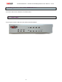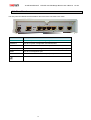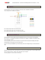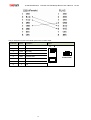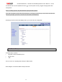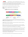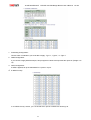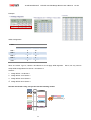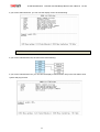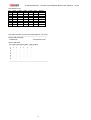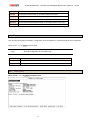
1
G.SHDSL.bis
3010E/3020E/3040E
User’s Manual
Version: A2
3010E/3020E/3040E
G.SHDSL.bis EFM Bridge Modem User’s Manual
Ver:A2
TABLE OF CONTENTS
1
2
3
INTRODUCTION....................................................................................................................................... 6
1.1
DESCRIPTION ..................................................................................................................................... 6
1.2
FEATURES .......................................................................................................................................... 7
1.3
SPECIFICATIONS ................................................................................................................................. 8
1.4
APPLICATIONS .................................................................................................................................... 9
GETTING TO KNOW ABOUT THE EFM MODEM ................................................................................. 10
2.1
FRONT PANEL .................................................................................................................................. 10
2.2
REAR PANEL .................................................................................................................................... 12
2.2.1
WAN Port................................................................................................................................... 13
2.2.2
LAN ports and MGMT port ...................................................................................................... 13
2.2.3
Console Port............................................................................................................................. 13
2.2.4
Power connection .................................................................................................................... 15
2.2.5
Reset Button............................................................................................................................. 15
2.2.6
Protective Earth (Frame Ground) terminal ............................................................................ 15
CONFIGURATION USING A WEB BROWSER...................................................................................... 16
3.1
CONFIGURATION METHOD ................................................................................................................. 16
3.1.1
Web configuration.................................................................................................................... 16
3.1.2
Serial console configuration................................................................................................... 16
3.1.3
Telnet configuration................................................................................................................. 16
3.2
INSTALLATION................................................................................................................................... 17
3.3
SETUP UP ON WEB BROWSER ........................................................................................................... 18
3.4
BASIC SETUP ................................................................................................................................... 19
3.4.1
Operation mode and MGMT .................................................................................................... 21
3.4.2
DHCP server ............................................................................................................................. 22
3.4.3
LAN............................................................................................................................................ 23
3.4.4
Review....................................................................................................................................... 24
3.5
ADVANCED SETUP ............................................................................................................................ 25
3.5.1
SHDSL.bis EFM ........................................................................................................................ 25
3.5.1.1
Link Type ........................................................................................................................................ 26
3.5.1.2
Annex Type..................................................................................................................................... 26
3.5.1.3
TCPAM Type ................................................................................................................................... 26
3.5.1.4
Main Rate........................................................................................................................................ 26
3.5.1.5
SNR margin .................................................................................................................................... 27
3.5.1.6
Line Probe ...................................................................................................................................... 27
3.5.2
VLAN ......................................................................................................................................... 28
3.5.2.1
Tag-Based VLAN ............................................................................................................................ 29
3.5.2.2
Port-Based VLAN ........................................................................................................................... 33
2
3010E/3020E/3040E
3.5.3
Ver:A2
QoS............................................................................................................................................ 36
3.5.3.1
Port Based Priority ........................................................................................................................ 37
3.5.3.2
VLAN Tag Priority .......................................................................................................................... 41
3.5.3.3
IP DSCP Priority ............................................................................................................................. 44
3.5.4
Rate Limiting ............................................................................................................................ 47
3.5.5
Flow Control ............................................................................................................................. 47
3.6
STATUS ............................................................................................................................................ 48
3.6.1
SHDSL .Bis EFM....................................................................................................................... 48
3.6.2
MGMT ........................................................................................................................................ 49
3.6.3
LAN............................................................................................................................................ 49
3.7
ADMINISTRATION .............................................................................................................................. 50
3.7.1
Security ..................................................................................................................................... 50
3.7.2
SNMP......................................................................................................................................... 53
3.7.2.1
Community Pool ............................................................................................................................ 54
3.7.2.2
Trap Host Pool................................................................................................................................ 55
3.8
4
G.SHDSL.bis EFM Bridge Modem User’s Manual
UTILITY ............................................................................................................................................ 56
3.8.1
System Info............................................................................................................................... 57
3.8.2
CONFIG Tool............................................................................................................................. 58
3.8.3
Upgrade..................................................................................................................................... 59
3.8.4
Logout ....................................................................................................................................... 59
3.8.5
Restart....................................................................................................................................... 60
CONFIGURATION USE SERIAL CONSOLE AND TELNET WITH MENU DRIVEN INTERFACE ........ 61
4.1
INTRODUCTION ................................................................................................................................. 61
4.1.1
Login to the Console Interface ............................................................................................... 61
4.1.2
Telnet login ............................................................................................................................... 62
4.1.3
Menu Driven Interface Commands......................................................................................... 62
4.1.4
Window structure..................................................................................................................... 64
4.2
M AIN MENU TREE ............................................................................................................................. 64
4.2.1
Menu tree for authorized user ................................................................................................ 64
4.2.2
Menu tree for unauthorized user ............................................................................................ 66
4.3
ENABLE ........................................................................................................................................... 67
4.4
SETUP ............................................................................................................................................. 69
4.4.1
SHDSL.bis................................................................................................................................. 69
4.4.1.1
Mode ............................................................................................................................................... 69
4.4.1.2
Link ................................................................................................................................................. 69
4.4.1.3
Annex.............................................................................................................................................. 70
4.4.1.4
TCPAM ............................................................................................................................................ 70
4.4.1.5
Maximum main rate ....................................................................................................................... 70
4.4.1.6
SNR Margin .................................................................................................................................... 70
4.4.1.7
Line Probe ...................................................................................................................................... 70
3
3010E/3020E/3040E
4.4.1.8
G.SHDSL.bis EFM Bridge Modem User’s Manual
Ver:A2
Clear................................................................................................................................................. 71
4.4.2
LAN........................................................................................................................................ 71
4.4.3
VLAN ....................................................................................................................................... 72
4.4.3.1
Mode ................................................................................................................................................ 72
4.4.3.2
802.11Q VLAN ................................................................................................................................. 73
4.4.3.3
Port Based VLAN ............................................................................................................................ 74
4.4.4
QoS............................................................................................................................................ 76
4.4.4.1
Mode ............................................................................................................................................... 76
4.4.4.2
Queue schedule .............................................................................................................................. 76
4.4.4.3
Queue weight...................................................................................................................................... 77
4.4.4.4
Queue egress rate .............................................................................................................................. 78
4.4.4.5
Port Based Priority QoS ................................................................................................................. 78
4.4.4.6
VLAN Tag Priority QoS .................................................................................................................. 78
4.4.4.7
IP DSCP Priority Qos ..................................................................................................................... 79
4.4.4.8
List.................................................................................................................................................. 80
4.4.5
RATE.......................................................................................................................................... 81
4.4.6
MGMT ........................................................................................................................................ 81
4.4.7
DHCP ......................................................................................................................................... 82
4.4.7.1
DHCP Server................................................................................................................................... 82
4.4.7.2
DHCP fixed Host ............................................................................................................................ 83
4.4.8
DNS proxy................................................................................................................................. 84
4.4.9
Host name................................................................................................................................. 84
4.4.10
4.5
Default................................................................................................................................... 85
STATUS ............................................................................................................................................ 85
4.5.1
Shdsl.bis ................................................................................................................................... 86
4.5.2
Interface .................................................................................................................................... 86
4.6
SHOW .............................................................................................................................................. 87
4.6.1
Show system ............................................................................................................................ 87
4.6.2
Show script............................................................................................................................... 88
4.7
WRITE.............................................................................................................................................. 88
4.8
REBOOT ........................................................................................................................................... 88
4.9
PING ................................................................................................................................................ 89
4.10
ADMINISTRATION .............................................................................................................................. 90
4.10.1
User Profile........................................................................................................................... 90
4.10.2
Security................................................................................................................................. 92
4.10.2.1
Telnet TCP port .............................................................................................................................. 92
4.10.2.2
IP address pool .............................................................................................................................. 92
4.10.3
SNMP .................................................................................................................................... 93
4.10.3.1
Community ..................................................................................................................................... 93
4.10.3.2
Trap host......................................................................................................................................... 94
4
3010E/3020E/3040E
4.10.4
4.11
Ver:A2
Supervisor Password and ID.............................................................................................. 96
4.10.4.1
Supervisor Password .................................................................................................................... 97
4.10.4.2
Supervisor ID ................................................................................................................................. 97
UTILITY ............................................................................................................................................ 98
4.11.1
Upgrade main software....................................................................................................... 98
4.11.2
Backup system configuration ............................................................................................ 98
4.11.3
Restore system configuration............................................................................................ 99
4.12
5.
G.SHDSL.bis EFM Bridge Modem User’s Manual
EXIT.............................................................................................................................................. 100
APPENDIX – SETUP TABLE................................................................................................................ 101
5
3010E/3020E/3040E
G.SHDSL.bis EFM Bridge Modem User’s Manual
Ver:A2
1 Introduction
1.1 Description
The EFM Based Network Extender provides a flexible and friendly solution for the Ethernet based services
provision to subscribers by the service provider. Additionally, this family of products provides a simple way in a
back-to-back deployment to provide point to point configuration. This allows broadband service providers to
deploy single DSL lines economically when required for low density geographical areas or during startup
phase.
The EFM Based Network Extender provides cost-effective symmetrical bandwidth at rates up to 15.3Mbps
which allows service providers to deliver friendly Ethernet services rapidly. The EFM Based Network
Extender extends the reach of Ethernet services to the sites with no fiber access to by using bonded copper
pairs. Designed with standard-based EFM technology (2BASE-TL), the delivery of Ethernet services with
EFM modem can be deployed quickly on the existing copper plant. It is a good application for back-to-back
connections between remote offices and enterprise headquarters.
The EFM Based Network Extender implements the management features based on IEEE 802.3ah standard
and it enables users to significantly reduce operation expenses by eliminating unnecessary transformations
between Ethernet and legacy ATM network. As based on user-friendly Ethernet, it saves time and costs
because of simple engineering task without additional trainings costs. Packet based technology which
architecture utilizes 100% packet transmission technology for optimum throughput and reliability. With a
compact form-factor design and optimization for the use over existing copper network, The EFM Based
Network Extender reduces the initial investment cost and deployment time in delivering higher speed
Ethernet services. It provides minimized risk bearing and quick return on investment to service providers and
enterprises
The EFM Based Network Extender can bond up to 1 pairs and deliver up to 15.3 Mbps Ethernet services to
all users within their service area by utilizing existing copper infrastructure and EFM 802.3ah PAF bonding
technology. Service Providers and enterprises are able to offer symmetrical high speed connectivity for
transparent Ethernet services on DSLAM backhaul or Wireless backhaul and more.
The EFM Based Network Extender provides future-proof features meeting Ethernet Quality of Service (QoS)
requirements by utilizing 802.1q VLAN capabilities, four levels of priorities, traffic flow control and rate control.
This traffic management and QoS features enable service providers to offer highly profitable and value-added
services to a vast majority of business and institutional sites.
6
3010E/3020E/3040E
G.SHDSL.bis EFM Bridge Modem User’s Manual
1.2 Features
Extending Ethernet Services to sites with existing copper infrastructure
EFM up to 15.3 Mbps max./pair (TC-PAM 128)
EFM Bonding up to 61 Mbps (4 pairs, TC-PAM 128)
Support EFM mode
Flexible and Rapid Service Deployment
Flexible configuration as CPE or CO
Support EFM OAM complying IEEE 802.3ah
Low Delay, Jitter and Packet Loss for delay sensitive applications
Comprehensive and easy OAM & P functions in provisioning and management
QoS feature for guaranteed Ethernet service
Future-proof Ethernet traffic management and QoS features
7
Ver:A2
3010E/3020E/3040E
G.SHDSL.bis EFM Bridge Modem User’s Manual
Ver:A2
1.3 Specifications
Network Interface
LAN : RJ45 x 4
Range1~4094)
LAN
Management Port: RJ45 x 1
VLAN Stacking (Q-in-Q)
4 –port switching hub
Console Port: RJ45 x 1
10/100BASE-T
Reset Button: Load Factory
Rate limiting by
auto-negotiation & sensing
Default
rule-based/port-based
Auto MDI/MDI-X
DC Power Jack x 1
Traffic classification based on
WAN
Indicator
QoS Support
port/802.1p/ DSCP
ITU-T G.991.2.(2004)
LAN : Link/Act, 10/100 per
WRR (Weighted Round
2BASE-TL
port
Robin)/ SPQ (Strict Priority
EFM bonding (IEEE 802.3ah
WAN: Link per loop
Queuing) scheduling
PAF)
System: Power/CO/CPE,
algorithm
Data Rate:
Alarm, MGMT
N x 64 Kpbs (N=3~89) using
TC-PAM 16/32
Management Interface
Environment
Operating Temperature:
Easy to use web-based GUI
-20°C ~ +60°C
Max. 5.696Mbps (1-Pair)
for quick setup, configuration
Storage Temperature: -40°C
Max. 11.392Mbps (2-Pair)
and management
~ +85°C
Max. 22.784Mbps (4-Pair)
Menu-driven
Relative Humidity: 98%,
N x 64 Kbps (N=3~239) using
interface/Command line
non-condensing
TC-PAM 64/128
interface (CLI ) for local
Regulatory
Max. 15.296 Mbps (1-Pair)
console and telnet access
ISO 9001 Quality
Max. 30.592 Mbps (2-Pair)
Password protected
Management
Max. 61.184 Mbps (4-Pair)
management and access
CE Approval & EN60950
Support of Annex A , Annex
control list for administration
Certificate
B , Annex AF & Annex BG
SNMP v1/v2
Support TC-PAM
(RFC1157/1901/1905) agent
Dimension (mm): 195 x 48 x
16/32/64/128
and MIB II (RFC1213/1493)
168
Impedance: 135 ohms
EFM OAM (IEEE 802.3ah)
AC Power Adapter
Software upgrade via
(100~240VAC with 50~60Hz)
web-browser/TFTP
Weight: 3010E: 1300g,
LAN Protocols
802.1d Transparent Bridging
Up to 2K MAC Address
learning bridge
Hardware Interface
WAN(DSL) : RJ-45 x 1
VLAN Support
IEEE 802.1q VLAN Tagging
Physical / Electrical
3020E: 1320g , 3040E :1340g
Memory
Port Based VLAN
2MB Flash Memory , 8MB
Up to 8 802.1q VLANs (ID
SDRAM
8
3010E/3020E/3040E
1.4 Applications
9
G.SHDSL.bis EFM Bridge Modem User’s Manual
Ver:A2
3010E/3020E/3040E
G.SHDSL.bis EFM Bridge Modem User’s Manual
2 Getting to know about the EFM Modem
This section will introduce hardware of the EFM modem.
2.1 Front Panel
The front panel contains LED which show status of the EFM Modem.
10
Ver:A2
3010E/3020E/3040E
G.SHDSL.bis EFM Bridge Modem User’s Manual
LED status of EFM Modem:
LEDs
Active
Description
Power on
PWR
On
Blue: CO mode
Green: CPE mode
On
SHDSL.bis line connection is dropped
Blink
SHDSL.bis self-test
On
Management port line connection is established
On
SHDSL.bis line 1 connection is established
Blink
SHDSL.bis line 1 handshake
LINK 2
On
SHDSL.bis line 2 connection is established
(optional)
Blink
SHDSL.bis line 2 handshake
LINK 3
On
SHDSL.bis line 3 connection is established
(optional)
Blink
SHDSL.bis line 3 handshake
LINK 4
On
SHDSL.bis line 4 connection is established
(optional)
Blink
SHDSL.bis line 4 handshake
LINK/ACT1
On
Ethernet cable is connected to LAN 1
LINK/ACT2
On
Ethernet cable is connected to LAN 2
LINK/ACT3
On
Ethernet cable is connected to LAN 3
LINK/ACT4
On
Ethernet cable is connected to LAN 4
On
LAN 1 is on 100M mode
Off
LAN 1 is on 10M mode
On
LAN 2 is on 100M mode
Off
LAN 2 is on 10M mode
On
LAN 3 is on 100M mode
Off
LAN 3 is on 10M mode
On
LAN 4 is on 100M mode
Off
LAN 4 is on 10M mode
ALM
MGMT
LINK 1
WAN
LAN
100M 1
100M 2
LAN
100M 3
100M 4
11
Ver:A2
3010E/3020E/3040E
G.SHDSL.bis EFM Bridge Modem User’s Manual
2.2 Rear Panel
The rear panel of G.SHDSL.bis EFM Modem where all of the connections are made.
Connector
Description
DC-IN
Power adaptor inlet: Input voltage range from 9V to 18V.
CONSOLE
RJ-45 for system configuration and maintenance
RST
Reset button for reboot or load factory default
LAN (1,2,3,4)
10/100BaseT auto-sensing and auto-MDIX for LAN port (RJ-45)
MGMT
RJ-45 for management port
DSL
G.SHDSL.Bis interface for WAN port (RJ-45)
Frame Ground / Protective earth
12
Ver:A2
3010E/3020E/3040E
G.SHDSL.bis EFM Bridge Modem User’s Manual
Ver:A2
2.2.1 WAN Port
The EFM modem have one port for WAN port connection, this is a G.SHDSL .bis interface
The pin assignments for SHDSL line cable are:
For one pair (2-wire) model, Loop1 has been used
For two pair (4-wire) model, Loop1 and 2 have been used
For four pair (8-wire) model, Loop1, 2, 3 and 4 have been used
2.2.2 LAN ports and MGMT port
The EFM modem have four LAN ports and one MGMT Ethernet port. Those ports are auto-negotiating,
auto-crossover. In 10/100Mbps Fast Ethernet, the speed can be 10Mbps or 100Mbps and the duplex mode
can be half duplex or duplex.
An auto-negotiating port can detect and adjust to the optimum Ethernet speed(10/100 Mbps) and duplex
mode(full duplex or half duplex) of the connected device.
An auto-crossover(auto-MDI/MDI-X) port automatically works with a straight-through or crossover Ethernet
cable.
2.2.3 Console Port
Connect the RJ-45 jack of the console cable to the console port of the EFM modem. Connect the DB-9 female
end to a serial port( COM1 , COM2 or other COM port) of your computer.
The wiring diagram of console cable is as following:
13
3010E/3020E/3040E
G.SHDSL.bis EFM Bridge Modem User’s Manual
The pin assignment of RJ-45 modular jack on the console cable:
Pin Number
Abbrev. Description
1
x
none
2
x
none
3
DTR
DTE ready
4
GND
Signal Ground
5
RXD
Received Data
6
TXD
Transmitted Data
7
x
none
8
x
none
Figure
1
8
1
8
Front View
Top View
14
Ver:A2
3010E/3020E/3040E
G.SHDSL.bis EFM Bridge Modem User’s Manual
Ver:A2
2.2.4 Power connection
Make sure you are using the correct power source as the AC/DC adapter. Inset the female end of power
adapter’s cord into the power receptacle on the rear panel. Connect the power adapter to an appropriate
power source.
2.2.5 Reset Button
The reset button can be used only in one of two ways.
(1)
Press the Reset Button for two second will cause system reboot.
(2)
Pressing the Reset Button for eight seconds will cause the product loading the factory default setting
and losing all of yours configuration. When you want to change its configuration but forget the user name or
password, or if the product is having problems connecting to the Internet and you want to configure it again
clearing all configurations, press the Reset Button for eight seconds with a paper clip or sharp pencil.
2.2.6 Protective Earth (Frame Ground) terminal
The marked lug or terminal should be connected to the building protective earth bus.
The function of protective earth does not serve the purpose of providing protection against electrical shock,
but instead enhances surge suppression on the DSL lines for installations where suitable bonding facilities
exist.
The connector type is M3 machine screw.
15
3010E/3020E/3040E
G.SHDSL.bis EFM Bridge Modem User’s Manual
Ver:A2
3 Configuration using a Web Browser
3.1 Configuration method
There are three methods to configure the EFM modem: serial console, Telnet and Web Browser. Users have
to choose one method to configure the EFM modem.
3.1.1 Web configuration
Make sure that Ethernet Adapter had been installed in PC or NB used for configuration of the modem. TCP/IP
protocol is necessary for web configuration, so please check the TCP/IP protocol whether it has been
installed.
The EFM modem provides a browser interface that lets you configure and manage the EFM modem. After you
set up your IP address for the EFM modem. You can access the EFM modem’s Web interface applications
directly in your browser by entering the IP address of the EFM modem. You can then use your Web browser to
list and manage configuration parameters from PC.
Web Configuration requires Internet Explorer 5.0 or later or Netscape Navigator 6.0 and later versions. The
recommended screen resolution is 1024 by 768 pixels.
3.1.2 Serial console configuration
For Serial Console, users can directly connecting a terminal or a PC equipped with a terminal-emulation
program (such as Hyper Terminal) to the EFM modem’s serial console port.
Use the supplied serial cable (RJ-45 to DB9F) is required to connect the EFM modem to PC. After marking
this connection, configure the terminal-emulation program to use the following parameters: 9600 bps , 8 data
bits , no parity and 1 stop bit.
3.1.3 Telnet configuration
Make sure that Ethernet Adapter had been installed in PC or NB used for configuration of the modem. The
EFM modem also supports telnet for remote configuration. The command is “telnet 192.168.1.1” .
It with
asks for user name and password for remote login when using telnet, please use “admin” for username and
“admin” for password. All display screen are as same as serial console configuration.
The IP address 192.168.1.1 is the default value and you can change to another one for you application.
16
3010E/3020E/3040E
G.SHDSL.bis EFM Bridge Modem User’s Manual
Ver:A2
3.2 Installation
The following guide is designed to lead users through Web Configuration of G.shdsl.bis EFM Modem in the
easiest and quickest way possible. Please follow the instructions carefully.
1.
Connect the power adapter to the port labeled “DC” on the rear panel of the EFM modem.
2.
Connect the Ethernet cable to MGMT port.
(Note: The EFM modem supported auto-MDIX switching hub so both straight through and cross-over
Ethernet cable can be used.)
3.
Connect the phone cable to the EFM modem and the other side of phone cable to wall jack.
4.
Connect the power adapter to power source.
5.
Turn on the PC or NB, which is used for configuration the EFM modem.
!
To avoid possible damage to this EFM modem, do not turn on the EFM modem before Hardware
Installation.
Connection with SHDSL .Bis EFM Modem
17
3010E/3020E/3040E
G.SHDSL.bis EFM Bridge Modem User’s Manual
Ver:A2
3.3 Setup up on Web Browser
This section introduces the configuration and functions of the web-based management.
It is an HTML-based management interface that allows easy EFM modem setup and management.
The EFM modem offers all monitoring and management features that allow users to manage this EFM
modem form anywhere on the network through a standard browser such as Internet Explorer.
TCP/IP setup
When DHCP function is enabled, the EFM modem acts as DHCP server in your network, the EFM modem will
automatically assign IP address for PC for management port connection.
For Window System, click the start button. Select setting and control panel.
Double click the network icon.
In the Configuration window, select the TCP/IP protocol line that has been associated with your network card
and then click property icon.
Choose IP address tab and select Obtain IP address automatically and then Click OK button.
System Login
User can use browser program such as Internet Explorer on your PC to connect the EFM Modem. Type
“http://” and the IP address like as “http://192.168.1.1”.
The default IP address and sub net-mask of the management port of EFM Modem are 192.168.1.1 and
255.255.255.0.
If DHCP function is disabled, your PC can set the same net-mask such as 192.168.1.X which X is from 2 to
254, that are also can connect.
Type User Name root and Password root and then click OK.
18
3010E/3020E/3040E
G.SHDSL.bis EFM Bridge Modem User’s Manual
Ver:A2
The default user name and password both is root. For the system security, suggest changing them after
configuration.
Note: For safety purpose, the password will be prompt as star symbol.
Note: After changing the User Name and Password, we strongly recommend you to save them because the
next time you login, you have to use the new User Name and Password.
Following is the first screen that displays when you access the web configurator.
3.4 Basic Setup
The Basic Setup contains:
Operation mode and MGMT port IP
DHCP server
LAN
User can use it to completely basic setup the EFM modem.
Below diagram is showed as Basic Setup’s flowchart.
19
3010E/3020E/3040E
20
G.SHDSL.bis EFM Bridge Modem User’s Manual
Ver:A2
3010E/3020E/3040E
3.4.1
G.SHDSL.bis EFM Bridge Modem User’s Manual
Ver:A2
Operation mode and MGMT
Click Basic for basic installation.
Click CPE (Customer Premises Equipment) side or CO (Central Office) side to setup the operation
mode.
When connection with EFM DSLAM, the SHDSL.bis EFM modem’s working mode is CPE. When “LAN to
LAN” connection, one side must be CO and the other side must be CPE.
Enter Parameters in MGMT item.
The EFM modem needs an IP address for it to be managed over the network. The factory default IP address
is 192.168.1.1. The subnet mask specifies the network number portion of an IP address. The factory default
subnet mask is 255.255.255.0 . You can configure another IP address in a different Subnet Mask for
management purposes.
IP: 192.168.1.1
Subnet Mask: 255.255.255.0
Host Name: SOHO
Some of the ISP requires the Host Name as identification. You may check with ISP to see if your Internet
service has been configured with a host name. In most cases, this field can be ignored.
And then, click Trigger DHCP service is Disable or Server. If you don’t need the DHCP service, please click
Disable.
21
3010E/3020E/3040E
3.4.2
G.SHDSL.bis EFM Bridge Modem User’s Manual
Ver:A2
DHCP server
Press Next to set the next page:
Dynamic Host Configuration Protocol (DHCP) is a communication protocol that lets network administrators to
manage centrally and automate the assignment of Internet Protocol (IP) addresses in an organization's
network. Using the Internet Protocol, each machine that can connect to the Internet needs a unique IP
address. When an organization sets up its computer users with a connection to the Internet, an IP address
must be assigned to each machine.
Without DHCP, the IP address must be entered manually at each computer. If computers move to another
location in another part of the network, a new IP address must be entered. DHCP lets a network administrator
to supervise and distribute IP addresses from a central point and automatically sends a new IP address when
a computer is plugged into a different place in the network.
The embedded DHCP server assigns network configuration information at most 253 users accessing the
Internet in the same time.
For example: If the LAN IP address is 192.168.0.1, the IP range of LAN is 192.168.0.2 to 192.168.0.254. The
DHCP server assigns the IP form Start IP Address to End IP Address. The legal IP address range is form 0 to
255, but 0 are reserved as network name and 255 are reserved for broadcast. It implies the legal IP address
22
3010E/3020E/3040E
G.SHDSL.bis EFM Bridge Modem User’s Manual
Ver:A2
range is from 1 to 254. That means you cannot assign an IP greater than 254 or less than 1.
Lease time 72 hours indicates that the DHCP server will reassign IP information in every 72 hours.
The default value is 72 hours .You can set up from 1 to 720 hours according to your application.
Moreover, you may assign a fixed IP address to a device while using DHCP; you have to put this device’s
MAC address in the Table of Fixed DHCP Host Entries.
3.4.3
LAN
Press Next to set the next page:
Enter Parameters in LAN:
LAN type item can be selected as: Disable, Dynamic IP and Static IP.
If you select Disable and Dynamic IP, can’t need input all IP address etc.
If you select Static IP, you can enter the following: IP, Subnet Mask, Gateway and DNS Server’s IP.
You must type the dotted decimal notation for DNS Server’s IP address
The default values are as following:
IP Address: 192.168.2.1
Subnet Mask: 255.255.255.0
Gateway: 0.0.0.0
DNS Server 1: 168.95.1.1
23
3010E/3020E/3040E
G.SHDSL.bis EFM Bridge Modem User’s Manual
Ver:A2
DNS Server 2: 168.95.192.1
DNS Server 3:
3.4.4
Review
Press Next to set the next page:
The screen will prompt the new configured parameters. Checking the parameters and Click Restart Then the
EFM modem will reboot and start working with new parameters or press or Continue to configure other
parameters.
24
3010E/3020E/3040E
G.SHDSL.bis EFM Bridge Modem User’s Manual
Ver:A2
3.5 Advanced Setup
Note: The advanced functions are only for advanced users to setup advanced functions. The incorrect setting
of advanced function will affect the performance or system error, even disconnection.
In “ADVANCED” section, users are allowed to change settings by different areas: SHDSL.bis EFM, QoS, Rate
Limiting, VLAN, and Flow Control.
3.5.1 SHDSL.bis EFM
You can setup the Link (number of wires), Annex type, TCPAM type, Main Rate, Main Rate, SNR margin and
Line Probe for SHDSL.bis EFM parameters.
Click SHDSL.bis EFM
25
3010E/3020E/3040E
G.SHDSL.bis EFM Bridge Modem User’s Manual
Ver:A2
3.5.1.1 Link Type
Line type means how many wire you want to use on SHDSL.bis connection.
Line Type
2-wire
EFM Modem
2-wire model
●
3.5.1.2 Annex Type
There are two Annex types: Annex AF and Annex BG in SHDSL.bis . Check with your ISP about it.
3.5.1.3 TCPAM Type
The default option is Auto. You may assign the different type manually as the following options.
1. Auto(16/32)
2. TCPAM-16
3. TCPAM-32
4. TCPAM-128
5. Optimal
3.5.1.4 Main Rate
You can setup the SHDSL.bis main rate is in the multiple of 64kbps , 128kpbs or 256 kpbs according using
which model.
Main Rate (Unit: kbps)
SHDSL.bis
multiple
EFM Modem
2-wire model
2-wire mode :
64
TCPAM-16
TCPAM-32
TCPAM-128
N=3~60
N=12~89
N=2~239
192 ~ 3840
768 ~ 5696
128 ~15296
Line Rate = Main Rate x 1
26
3010E/3020E/3040E
G.SHDSL.bis EFM Bridge Modem User’s Manual
Ver:A2
3.5.1.5 SNR margin
SNR margin is an index of line connection quality. You can see the actual SNR margin in STATUS SHDSL.bis.
The larger is SNR margin; the better is line connection quality.
For example, if you set SNR margin in the field as 5, the SHDSL.bis connection will drop and reconnect when
the SNR margin is lower than 5. On the other hand, the device will reduce the line rate and reconnect for
better line connection quality.
The range of SNR margin setting are -10 to 21.
3.5.1.6 Line Probe
For adaptive mode, you can setup the Line Probe to Enabled. The EFM modem will adapt the data rate
according to the line status. Otherwise, setup to Disabled.
The screen will prompt the parameters that will be written in NVRAM. Check the parameters before writing in
NVRAM.
Press Restart to restart the EFM modem working with new parameters or press continue to setup another
parameter.
27
3010E/3020E/3040E
G.SHDSL.bis EFM Bridge Modem User’s Manual
Ver:A2
3.5.2 VLAN
Click VLAN to configure VLAN.
VLAN (Virtual Local Area Network) allows a physical network to be partitioned into multiple logical networks.
Devices on a logical network belong to one group. A device can belong to more than one group. With VLAN, a
device cannot directly talk to or hear from devices that are not in the same group.
With MTU (Multi-Tenant Unit) applications, VLAN is vital in providing isolation and security among the
subscribers. When properly configured, VLAN prevents one subscriber from accessing the network resources
of another on the same LAN.
VLAN also increases network performance by limiting broadcasts to a smaller and more manageable logical
broadcast domain. In traditional switched environments, all broadcast packets go to each every individual port.
With VLAN, all broadcasts are confined to a specific broadcast domain.
For VLAN Configuration, users are able to choose the following options:
1.
Disable: to disable VLAN feature.
2.
Port-based VLAN: to group ports and their mode (access or trunk)
3.
Tag-based VLAN: to assign a VID and group ports with their modes (access or trunk).
28
3010E/3020E/3040E
G.SHDSL.bis EFM Bridge Modem User’s Manual
Ver:A2
3.5.2.1 Tag-Based VLAN
Click the Tag-Based VLAN to configure the EFM modem.
En:
Check if you want to apply this rule.
VID:
VLAN ID
MGMT:
Check if you want this rule to manage the modem.
Port:
port interfaces, including LAN1, LAN2, LAN3, LAN4, and DSL. Check the port interface you
need if you want to include the port.
Access:
allows all packets passing through the port interface
Trunk:
only these packets with assigned VLAN ID can pass through via the port interface.
Hybrid:
if the incoming packet carries a VLAN ID, then, the EFM modem will check the
VLAN ID with the assigned PVID.
If the packet includes no VLAN ID, then, the
EFM will not check.
Tunnel:
if you would like to enable Q-in-Q mode or VLAN mapping feature, please choose
this access mode.
S-VLAN Tunnel: this section is for “Tunnel” mode.
Mode:
to choose either you want to run “Q-in-Q” or “VLAN mapping”.
TPID:
Tag Protocol Identifier, a 16-bit field set to a value of 0x8100 (the typical value) for
identifying the frame as an IEEE 802.1Q-tagged frame.
“Mapping”, you are not allowed to change this value.
VID:
VLAN ID.
29
Note: when you choose
3010E/3020E/3040E
G.SHDSL.bis EFM Bridge Modem User’s Manual
Ver:A2
EXAMPLE:
Group
ID
Enable
VID
1
10
2
20
3
30
4
40
Port
MGM
T
LAN1
LAN2
LAN3
20
30
40
S-VLAN Tunnel
LAN4
DSL
Mode
TPI
D
VID
5
6
7
8
PVID
“VID” is basically for grouping port interfaces. This means only group members can access the other group
members.
For example, there is a VID group with LAN1, LAN3 and DSL.
DSL can only access to LAN1 and LAN3.
This means packets come from
Others cannot access to these group members.
“PVID” is for the EFM modem to check target packets, such as an ingress packet or an egress packet, for their
validity.
In 802.1q, the VLAN information is written into the Ethernet packet itself. Each packet carries a VLAN ID
(Virtual LAN ID), called a tag. This allows VLANs to be configured across multiple switches. Note that it’s
possible for VLAN tags to be stripped by H/W and/or S/W.
When using 802.1q, four bytes are added to the Ethernet frame, of which 12 bits are used for the VLAN ID.
Theoretically, there can be up to 4096 VLANs per network.
An Ethernet packet that contains a VLAN ID is called a tagged packet. Conversely, an Ethernet packet with no
VLAN ID is called an untagged packet. Typically all packets leave untagged, unless tagged by the adapter
prior to arriving at the switch port.
Egress and Ingress Rules:
Egress rules determine which frames can be transmitted out of a port, based on the Egress List of the VLAN
associated with it. Each VLAN has an Egress List that specifies the ports out of which frames can be
forwarded, and specifies whether the frames will be transmitted as tagged or untagged frames.
Ingress rules are a means of filtering out undesired traffic on a port. When Ingress Filtering is enabled, a port
determines if a frame can be processed based on whether the port is on the Egress List of the VLAN
associated with the frame.
When an untagged packet arrives at the switch port, the switch will write a VLAN ID into the header of the
30
3010E/3020E/3040E
G.SHDSL.bis EFM Bridge Modem User’s Manual
Ver:A2
frame according to the PVID (port VLAN) port definition. Typically, most switches today have all ports are set
to a default PVID of 1. When a tagged frame arrives at a switch port the tag is respected.
A VID defines the member of a port group. A packet can only travel inside a member port when the member
port is part of a VID port group. Different VID groups aren’t visible to one another
VID: (Virtual LAN ID) It is an definite number of ID which number is from 1 to 4094.
PVID: (Port VID) It is an untagged member from 1 to 4094 of default VLAN.
Link Type:
1. Access means the port can receive or send untagged packets.
2. Trunk means that the port can receive or send tagged packets.
TCI (Tag Control Information field) including user priority, Canonical format indicator (CFI) and VLAN ID.
TPID (Tag Protocol Identifier) defined value of 8100 in hex. When a frame has the EtherType equal to 8100H,
this frame carries the tag IEEE 802.1Q / 802.1P.
3
Priority field defines user priority, giving eight (2 = 8) priority levels. IEEE 802.1P defines the operation for
these 3 user priority bits. (Refer to following table)
CFI (Canonical Format Indicator) is always set to zero for Ethernet switches. CFI is used for compatibility
reason between Ethernet type network and Token Ring type network. If a frame received at an Ethernet port
has a CFI set to 1, then that frame should not be forwarded as it is to an untagged port.
VID (VLAN ID) is the identification of the VLAN, which is basically used by the standard 802.1Q. It has 12 bits
12
and allow the identification of 4096 (2 ) VLANs. Of the 4096 possible VIDs, a VID of 0 is used to identify
priority frames and value 4095 (FFF) is reserved, so the maximum possible VLAN configurations are 4,094.
The EFM modem initially default configures one VLAN, VID=1.
A port such as LAN1 to 4, DSL or sniffing can have only one PVID, but can have as many VID as the EFM
modem has memory in its VLAN table to store them.
Ports in the same VLAN group share the same frame broadcast domain thus increase network
31
3010E/3020E/3040E
G.SHDSL.bis EFM Bridge Modem User’s Manual
Ver:A2
performance through reduced broadcast traffic. VLAN groups can be modified at any time by adding, moving
or changing ports without any re-cabling.
Before enabling VLANs for the EFM modem, you must first assign each port to the VLAN group(s) in which it
will participate. By default all ports are assigned to VLAN1 as untagged ports. Add a port as a tagged port if
you want it to carry traffic for one or more VLANs, and any intermediate network devices or the host at the
other end of the connection supports VLANs. Then assign ports on the other VLAN-aware network devices
along the path that will carry this traffic to the same VLAN(s), either manually or dynamically using GVRP.
However, if you want a port on this EFM modem to participate in one or more VLANs, but none of the
intermediate network devices nor the host at the other end of the connection supports VLANs, then you
should add this port to the VLAN as an untagged port.
Note: VLAN-tagged frames can pass through VLAN-aware or VLAN-unaware network
Inter-connection devices, but the VLAN tags should be stripped off before passing it on to any end-node host
that does not support VLAN tagging.
VLAN Classification – When the EFM modem receives a frame, it classifies the frame in one of two ways. If
the frame is untagged, the EFM modem assigns the frame to an associated VLAN (based on the default
VLAN ID of the receiving port). But if the frame is tagged, the EFM modem uses the tagged VLAN ID to
identify the port broadcast domain of the frame.
Port Overlapping – Port overlapping can be used to allow access to commonly shared network resources
among different VLAN groups, such as file servers or printers.
32
3010E/3020E/3040E
G.SHDSL.bis EFM Bridge Modem User’s Manual
Ver:A2
Untagged VLANs – Untagged (or static) VLANs are typically used to reduce broadcast traffic and to increase
security. A group of network users assigned to a VLAN form a broadcast domain that is separate from other
VLANs configured on the EFM modem. Packets are forwarded only between ports that are designated for the
same VLAN. Untagged VLANs can be used to manually isolate user groups or subnets.
PVID - VLAN ID assigned to untagged frames received on the interface. (Default: 1)
If an interface is not a member of VLAN 1 and you assign its PVID to this VLAN, the interface will
automatically be added to VLAN 1 as an untagged member. For all other VLANs, an interface must first be
configured as an untagged member before you can assign its PVID to that group.
Link Type - Sets the port to accept the frame types: “Access” means the port can only receive or send
untagged frame types. “Trunk” means that the port can only receive or send tagged frame types.
3.5.2.2 Port-Based VLAN
Click Port-Based VLAN to configure the EFM modem.
Port-Based VLANs are VLANs where the packet forwarding decision is based on the destination MAC
address and its associated port.
When using the port-based VLAN, the port is assigned to a specific VLAN independent of the user or system
attached to the port. This means all users attached to the port should be members in the same VLAN. The
network administrator typically performs the VLAN assignment. The port configuration is static and cannot be
automatically changed to another VLAN without manual reconfiguration.
As with other VLAN approaches, the packets forwarded using this method do not leak into other VLAN
domains on the network. After a port has been assigned to a VLAN, the port cannot send to or receive from
devices in another VLAN.
33
3010E/3020E/3040E
G.SHDSL.bis EFM Bridge Modem User’s Manual
Ver:A2
MGMT:
check if the rule is for management purpose.
Port:
port interfaces, including LAN1, LAN2, LAN3, LAN4, and DSL. Check the port interface you
need if you want to include the port.
Access:
allows all packets passing through the port interface
Tunnel:
check the VLAN ID of all packets with VID assigned.
S-VLAN Tunnel:
TPID:
Tag Protocol Identifier, a 16-bit field set to a value of 0x8100 (the typical value) for
identifying the frame as an IEEE 802.1Q-tagged frame.
VID:
VLAN ID.
EXAMPLE:
Group ID
S-VLAN
Port
MGMT
LAN1
LAN2
LAN3
Tunnel
LAN4
DSL
TPID
VID
1
2
3
4
Acces
Tunne
Acces
Acces
Acces
0x810
5
s
l
s
s
s
0
6
7
8
From the image, you can conclude the information showed as above table.
We know there are three rules created.
34
10
3010E/3020E/3040E
G.SHDSL.bis EFM Bridge Modem User’s Manual
Ver:A2
(1) Group ID = 1
This group is allowed to manage the EFM modem.
LAN1, LAN2 and DSL are in this group.
Only LAN2 (in “Tunnel” mode) will check the VLAN ID of incoming packets.
The VLAN ID
should be equal to 10 and its TPID should be “0x8100”.
(2) Group ID = 2
This group is allowed to manage the EFM modem.
LAN3 and LAN4 are in this group.
This rule
will not check any VLAN ID from any group member (both ports are “Access”).
(3) Group ID = 3
This group is not allowed to manage the EFM modem.
group.
LAN1, LAN2, LAN4 and DSL are in this
Only packets with VLAN ID = 10 and TPID = 0x8100 can access LAN2; otherwise, packets
which do not meet this requirement will be dropped.
35
3010E/3020E/3040E
G.SHDSL.bis EFM Bridge Modem User’s Manual
Ver:A2
3.5.3 QoS
QoS(Quality of Service) refers to both a network’s ability to deliver data with minimum delay, and the
networking methods used to control the use of bandwidth. Without QoS, all traffic date is equally likely to be
dropped when the network is congested. This can cause a reduction in network performance and mark the
network inadequate for time-critical application such as video-on-demand.
Click QoS to configure QoS
QoS (Quality of Service) is to decide which PCs can get the priorities to pass though EFM modem once if the
bandwidth is exhausted or fully saturated.
The priority modes have three types: Port Based Priority, VLAN Tag Priority and IP DSCP Priority. You can
also set Disable the QoS function.
36
3010E/3020E/3040E
G.SHDSL.bis EFM Bridge Modem User’s Manual
Ver:A2
3.5.3.1 Port Based Priority
When you click Port Based Priority, it will show the following:
Select the ports to which the rule should be applied.
There have six ports can be applied: LAN1, LAN2, LAN3, LAN4, DSL and Sniffing
For Port Based Priority, it can setup the queue type from type 0 to type 3.
The common setting tables are:
WRR configuration: Each queue type can setup the queue weight form 1 to 15.
WFQ configuration: Each ports and their queue type can set the bandwidth.
1. Scheduling Configuration
This modem provides three combinations of four commonly used techniques, type1, type 2 and type 3.
Choose which combination you would like to apply and fill up the corresponding information.
37
3010E/3020E/3040E
G.SHDSL.bis EFM Bridge Modem User’s Manual
Ver:A2
WRR (Weighted Round Robin): All received packets will be stored into queue 1, queue 2, queue 3, and
queue 4.
Users will assign a weighting for each queue.
Then, WRR will re-pack all packets from four
queues based on the weightings.
New Packet
For example, as showed in the above image, the weightings of each queue are 4, 2, 5, and 1. When
5600I Series starts to process all packets in these queues with WRR algorithm, a new packet will look like
the packet showed on the right hand side.
Then, 5600I Series sends out the new packets.
WFQ (Weighted Fair Queuing): WFQ is a generalization of processor sharing, which allows several
sessions share the same link.
LAN 1 20, LAN 2 15, LAN 3…
LAN 1 20, LAN 2 15, LAN 3…
LAN 1 40, LAN 2 10, LAN 3…
LAN 1 5, LAN 2 30, LAN 3…
Users assign data size of each queue can be accepted by each port in “WFQ Configuration” section.
BE (Best Effort):
Best Effort QoS is mainly used for data which has lower priority or can be delay.
traffic priority will be given in BE algorithm.
priority, such as, video or voice data.
38
No
Hence, this algorithm is not suitable for data that has higher
3010E/3020E/3040E
G.SHDSL.bis EFM Bridge Modem User’s Manual
SP (Strictly Priority): Strictly Priority Algorithm simply follows priorities only.
Ver:A2
This means the algorithm
transmits the highest priority queue first, then, the next highest priority queue, and so on.
However, if there
are always some content in the highest priority queue, then the other packets in the rest of queues will not
be sent until the highest priority queue is empty.
This algorithm is preferred when the received packets
contain some high priority data, such as, voice and video.
39
3010E/3020E/3040E
G.SHDSL.bis EFM Bridge Modem User’s Manual
Ver:A2
2. WRR Configuration
If the user chooses “Type 1” in “Scheduling Configuration” section, then the information in “WRR
Configuration” section is required to be filled in.
Users are able to assign from 1 to 15 for the value of a
weight for each queue.
3. WFQ Configuration
If users choose to apply “Type 2” or “Type 3” as the QoS algorithm, users should assign the bandwidth for
each queue in each port.
4. Port Based Priority
The last step is to assign queues with their corresponding ports, LAN 1, LAN 2, LAN 3, LAN 4, DSL and
Sniffing.
Example:
40
3010E/3020E/3040E
G.SHDSL.bis EFM Bridge Modem User’s Manual
If we choose “Type 3”, then we know our queues will apply BE, WFQ, WFQ, and SP techniques.
assign which port should go to which queue.
Assume the following settings…
Port
Queue
Algorithm
LAN 1
3
SP
LAN 2
0
BE
LAN 3
1
WFQ
LAN 4
1
WFQ
DSL
2
WFQ
Sniffing
2
WFQ
Then, we can know the corresponding algorithm for each port as the table above.
3.5.3.2 VLAN Tag Priority
When you click VLAN Tag Priority, it will show the following:
41
Ver:A2
Then, we
3010E/3020E/3040E
G.SHDSL.bis EFM Bridge Modem User’s Manual
Ver:A2
VLAN Tag Priority uses the tag field information which has been inserted into an Ethernet frame. If a port has
an 802.1Q-compliant device attached (such as this modem), these tagged frames can carry VLAN
membership information.
IEEE 802.1Q Tagged Frame for Ethernet:
3
User priority is giving eight ( 2 = 8 ) priority levels. The default value is 0, indicating normal treatment.
Priority Level Traffic Type
0 (default)
Best Effort
1
Background
2
Spare
3
Excellent Effort
4
Controlled Load
5
Video, less than 100 milliseconds latency and jitter
6
Voice, less than 10 milliseconds latency and jitter
7
Network Control
Each Priority level can be set queue from 0 to 3.
Scheduling Configuration item can setup the type is from 1 to 3. Queue from 0 to 3 can set up their Queue
Weight form 1 to 15.
1
Scheduling Configuration:
Choose which algorithm combination you would like to apply.
42
3010E/3020E/3040E
2
G.SHDSL.bis EFM Bridge Modem User’s Manual
Ver:A2
WRR Configuration:
If you would like to apply WRR as the QoS algorithm for your EFM modem, then, please assign the weight
for each queue.
“Weight” means how important the queue is; therefore, 15 is the most important queue
and 0 is the least important queue.
Hence, in the image below, we know queue 3 is the most important
queue among all.
3
WFQ Configuration:
Same as other priority style, assign a bandwidth for a queue in one port in this section if WFQ algorithm is
chose.
4
VLAN Tag Priority
“VLAN Tag Priority” section allows users to choose a packet with an assigned priority goes to which
queue.
Example:
Assume we choose “Type 1” in “Scheduling Configuration” section.
Queue
Weight
0
1
2
3
2
15
7
8
Priority
0
1
2
3
4
5
6
7
Queue
0
0
2
2
3
3
1
1
43
3010E/3020E/3040E
G.SHDSL.bis EFM Bridge Modem User’s Manual
Ver:A2
Hence, we know…
1. Packets with priority 0 and priority 1 go to Queue 0.
2. Packets with priority 2 and priority 3 go to Queue 2.
3. Packets with priority 4 and priority 5 go to Queue 3.
4. Packets with priority 6 and priority 7 go to Queue 1.
5. When, data flow traffic is jammed…
Queue 1 Packets will go first because weight is equal to 15 (the biggest value).
Queue 3 Packets will go next because the weight is the second largest value.
Queue 2 Packets are the next after Queue 3 Packets.
Queue 0 Packets are the last one to send.
3.5.3.3 IP DSCP Priority
IP DSCP:
DSCP stands for “Differentiated Services Code Point”, which is the 6-bit field in the header of IP
packets, and it is for packet classification purposes.
IP header.
Hence, this algorithm is based on IP DSCP fields in the
Therefore, there are 64 levels of priority degrees. (0 to 63)
DSCP: bit 8 to bit 13
44
3010E/3020E/3040E
G.SHDSL.bis EFM Bridge Modem User’s Manual
Ver:A2
1. Scheduling Configuration:
Choose which combination you would like to apply: “Type 1”, “Type 2”, or “Type 3”.
2. WRR Configuration:
If you choose to apply WRR technique, fill up weights to indicate how important the queue is. (Weight: 0 to
15)
3. WFQ Configuration:
If WFQ is applied, fill up the bandwidth for a queue in a port.
4. IP DSCP Priority:
In “IP DSCP Priority” section, you can decide which queue a DSCP level should go to.
45
3010E/3020E/3040E
G.SHDSL.bis EFM Bridge Modem User’s Manual
Ver:A2
Example:
WFQ Configuration
Port
Queue
0
1
2
LAN 1
5
10
LAN 2
5
0
LAN 3
0
10
LAN 4
0
0
DSL
5
0
3
Since we choose “Type 3”, Queue 0 and Queue 3 do not apply WFQ algorithm.
setup WFQ configurations for Queue 1 and Queue 2.
Assume…
1. Assign DSCP 1 to Queue 0.
2. Assign DSCP 14 to Queue 1.
3. Assign DSCP 34 to Queue 2.
4. Assign DSCP 55 to Queue 3.
Now we check LAN 1 only, and you will see the following results.
46
Hence, we only need to
3010E/3020E/3040E
G.SHDSL.bis EFM Bridge Modem User’s Manual
Ver:A2
3.5.4 Rate Limiting
Click Rate Limiting to configure the EFM modem.
Limiting bandwidth to specific users and ports helps control network congestion, ensure high performance,
create efficient networks, and prevent a small number of users from monopolizing network bandwidth.
Rate limiting control can be used to intelligently manage bandwidth allocation in the networking. It can prevent
one user or device from dominating the available network bandwidth, and it allows IT managers to allocate
greater bandwidth to the departments and applications that need it.
You can setup the date rates limit on each port from 0 to 22. (00 means No limit, the Ingress Rate x 1024kbps
is the limit rate of their ports. The default setting is No limit on each ports.)
3.5.5 Flow Control
“Flow Control” Section allows users to decide whether this modem should control the packet size.
47
3010E/3020E/3040E
G.SHDSL.bis EFM Bridge Modem User’s Manual
Ver:A2
3.6 Status
When you click STATUS You can monitor the following : SHDSL.bis EFM, MGMT and LAN.
3.6.1 SHDSL .Bis EFM
SHDSL.bis status including run-time device status : SHDSL.bis mode and Line Rate and Performance
information:
SNR margin, attenuation and CRC error count.
4-pairs model (8 wire model)will showed as following, you can know about their four channel run-time
status( from channel 1 to 4).
Below display screen is come from four pair model(8 wire model):
If two EFM modem have been linking together, you can know about their run-time line rate status and
performance information from this screen.
Note: CPE side’s line rate according to the setting of CO side.
If you want to clear the performance data on ERC Error Count, click Clear CRC Error is O.K.
48
3010E/3020E/3040E
G.SHDSL.bis EFM Bridge Modem User’s Manual
3.6.2 MGMT
MGMT status will display the MGMT interface information.
You can view the general status of MGMT interface and DHCP client table.
3.6.3 LAN
LAN status will prompt the setting on IP type, IP address and Subnet mask.
For example, it shows the IP type of LAN interface is Fixed:
49
Ver:A2
3010E/3020E/3040E
G.SHDSL.bis EFM Bridge Modem User’s Manual
Ver:A2
3.7 Administration
This session introduces Administration including SECURITY and SNMP (simple network management
protocol).
3.7.1 Security
For system security, suggest to change the default user name and password in the first setup otherwise
unauthorized persons can access the EFM modem and change the parameters.
Press Security to setup the parameters.
For better security, change the Supervisor ID and Supervisor password for the EFM modem. If you don’t set
them, all users can be able to access the EFM modem using the default Supervisor ID and Supervisor
Password is “root”.
You can authorize five legal users to access the EFM modem via telnet or console only. There are two UI
50
3010E/3020E/3040E
G.SHDSL.bis EFM Bridge Modem User’s Manual
Ver:A2
modes, menu driven mode and command mode to configure the EFM modem.
The default user name on and Password are “admin”.
There are two UI modes, menu and command mode for telnet or console mode to setup the EFM modem.
The menu is meaning menu driven interface mode and Command is meaning line command mode. We will
not discuss command mode in this manual.
Telnet Console mode:
User name
Password
Supervisor Password
All function can use
Can only use ping test, view the status and configuration
Exit
Web Brower mode:
Supervisor ID
Supervisor Password
All function can use
Logout
There have a Telnet Port number setting. The default value is 23.
51
3010E/3020E/3040E
G.SHDSL.bis EFM Bridge Modem User’s Manual
Ver:A2
Legal address pool will setup the legal IP addresses from which authorized person can configure the EFM
modem. This is the more secure function for network administrator to setup the legal address of configuration.
Configured 0.0.0.0 will allow all hosts on Internet or LAN to access the EFM modem.
Leaving blank of trust host list will cause blocking all PC from WAN to access the EFM modem. On the other
hand, only PC in LAN can access the EFM modem.
If you type the exact IP address in the filed, only the host can access the EFM modem.
Click Finish to finish the setting.
The browser will prompt the configured parameters and check it before writing into NVRAM.
Press Restart to restart the EFM modem working with the new parameters and press Continue to setup other
parameters.
52
3010E/3020E/3040E
G.SHDSL.bis EFM Bridge Modem User’s Manual
Ver:A2
3.7.2 SNMP
Simple Network Management Protocol (SNMP) provides for the exchange of messages between a network
management client and a network management agent for remote management of network nodes. These
messages contain requests to get and set variables that exist in network nodes in order to obtain statistics, set
configuration parameters, and monitor network events. SNMP communications can occur over the LAN or
WAN connection.
The EFM modem can generate SNMP traps to indicate alarm conditions, and it relies on SNMP community
strings to implement SNMP security.
This EFM modem support both MIB I and MIB II.
Click SNMP to configure the parameters.
53
3010E/3020E/3040E
G.SHDSL.bis EFM Bridge Modem User’s Manual
Ver:A2
3.7.2.1 Community Pool
An SNMP community is the group that devices and management stations running SNMP belong to. It helps
define where information is sent. The community name is used to identify the group. A SNMP device or agent
may belong to more than one community. It will not requests from management stations that do not belong to
one of its communities.
SNMP default communities are:
Access Right
Community
Read
public
Write
private
Press Modify to set up community pool.
In the table of current community pool, you can setup the access authority.
Status:
Enable: for turn on the SNMP function
Disable: for turn off the SNMP function
Access Right: Deny for deny all access
Read for access read only
Write for access read and write.
Community:
It serves as password for access right.
After configuring the community pool, press Finish.
The browser will prompt the configured parameters and check it before writing into NVRAM.
Press Restart to restart the EFM modem working with the new parameters and press Continue to setup other
parameters.
54
3010E/3020E/3040E
G.SHDSL.bis EFM Bridge Modem User’s Manual
Ver:A2
3.7.2.2 Trap Host Pool
In the table of current trap host pool, you can setup the trap host.
SNMP trap is an informational message sent from an SNMP agent to a manager. It is a management station
(SNMP application) that receives traps.
If no trap host pool is defined, no traps are issued.
Press Modify to set up trap host pool.
Version: select version for trap host. (Version 1 is for SNMPv1; Version 2 for SNMPv2).
Disable for turn off
IP Address: type the trap host IP address
Community: type the community password.
Press OK to finish the setup.
The browser will prompt the configured parameters and check it before writing into NVRAM.
Press Restart to restart the EFM modem working with the new parameters and press Continue to setup other
parameters.
55
3010E/3020E/3040E
G.SHDSL.bis EFM Bridge Modem User’s Manual
3.8 Utility
This section will describe the UTILITY of the EFM modem.
The UTILITY menu including:
SYSTEM INFO: system information,
CONFIG TOOL: load the factory default configuration,
UPGRADE: upgrade the firmware
LOGOUT: logout the system
RESTART: restart the EFM modem.
56
Ver:A2
3010E/3020E/3040E
G.SHDSL.bis EFM Bridge Modem User’s Manual
Ver:A2
3.8.1 System Info
For review the information, click SYSTEM INFO to display the screen as shown below.
You can check the MCSV, Software Version, Chipset, Firmware Version, Host Name and System Up Time.
The System Up Time item let you know the EFM modem how long time after power on.
57
3010E/3020E/3040E
G.SHDSL.bis EFM Bridge Modem User’s Manual
Ver:A2
3.8.2 CONFIG Tool
This configuration tool has three functions: load Factory Default, Restore Configuration, and Backup
Configuration.
Press CONFIG TOOL, you can view the following:
Choose the function and then press Finish.
Load Factory Default: It will load the factory default parameters to the EFM modem.
Note: This action will change all of the settings to factory default. On the other hand, you will lose all the
existing configured parameters.
Restore Configuration:
In case of the configuration crushed occasionally, it will help you to recover the backup configuration easily.
Click Finish after selecting Restore Configuration.
Browse the route of backup file then press finish. The EFM modem will automatically restore the saved
configuration.
Backup Configuration:
After configuration, suggest using the function to back up your EFM modem parameters in the PC. Select the
Backup Configuration and then press Finish. Browse the place of backup file named backup. Press Finish.
The EFM modem will automatically backup the configuration.
58
3010E/3020E/3040E
G.SHDSL.bis EFM Bridge Modem User’s Manual
Ver:A2
3.8.3 Upgrade
You can upgrade the firmware of EFM modem using the upgrade function.
Press Upgrade in UTILITY menu.
Type the path and file name of the firmware file you wish to upload to the EFM modem in text box or click
Browse to locate it. Press OK button to upgrade. The system will reboot automatically after finishing.
(Firmware upgrades are only applied after a reboot)
After the firmware upgrade process is complete, you can see the SYSTEM INFO screen to verify your current
firmware version number.
3.8.4 Logout
To exit the web configurator, press LOGOUT. You have to log in with your password again after you log out.
This is recommended after you finish a management session for security reasons.
59
3010E/3020E/3040E
G.SHDSL.bis EFM Bridge Modem User’s Manual
Ver:A2
3.8.5 Restart
For restarting the EFM modem, press Restart to reboot the EFM modem.
When you press Restart, display screen is as following:
It show the configuration is success. When the system have rebooted later, you can re-open the browser.
60
3010E/3020E/3040E
G.SHDSL.bis EFM Bridge Modem User’s Manual
Ver:A2
4 Configuration use Serial Console and Telnet with Menu Driven
Interface
4.1 Introduction
4.1.1 Login to the Console Interface
The console port is a RJ-48C connector that enables a connection to a PC for monitoring and configuring the
EFM modem. Use the supplied serial cable with a female DB-9 connector to serial port of PC and RJ-48C
module jack connector to EFM modem’s console port. Start your terminal access program by terminal
emulation program or Hyper Terminal and configure its communication parameters to match the following
default characteristics of the console port:
Parameter
Value
Baud rate
9600
Data Bits
8
Parity Check
None
Stop Bits
1
Flow-control
None
After finished the parameter settings, press the SPACE key until the login screen appears. When you see the
login screen, you can logon to this EFM Modem.
Note: Only SPACE key invoke the login prompt. Pressing other keys does not work.
The system asks for User and Password, please enter “admin” both for the factory default password. As show
in the following:
User: admin
Password: *****
61
3010E/3020E/3040E
G.SHDSL.bis EFM Bridge Modem User’s Manual
Ver:A2
4.1.2 Telnet login
The EFM modem also supports telnet for remote management.
Make sure the correct Ethernet cable connected the MGMT port of EFM modem to your computer. The
MGMT indicator on the front panel shall light if a correct cable is used. Starting your Telnet client with VT100
terminal emulation and connecting to the management IP of EFM modem, wait for the login prompt appears.
Input User and Password after login screen pop up. The system asks for User and Password, please enter
“admin” both for the factory default password.
As show in the following:
User: admin
Password: *****
Note: The default IP address is 192.168.1.1. So that the line command is “telnet 192.168.1.1” on DOS mode.
4.1.3 Menu Driven Interface Commands
Before changing the configuration, familiarize yourself with the operations list in the following table. The
operation list will be shown on the window.
Menu Driven Interface Commands:
Keystroke
Description
[UP] or I
Move to above field in the same level menu.
[DOWN] or K
Move to below field in the same level menu.
[LEFT] or J
Move back to previous menu.
[RIGHT] , L or [ENTER]
Move forward to submenu.
[HOME]or U
Move to first field
[END] or O
Move to last field
[TAB]
To choose another parameters.
62
3010E/3020E/3040E
G.SHDSL.bis EFM Bridge Modem User’s Manual
Ctrl + C
To quit the configuring item.
Ctrl + Q
For help
Ver:A2
For serial console and Telnet management, the EFM Modem implements the menu driven interface. It can
show you all of available commands for you to select. You don’t need to remember the command syntax and
save your time on typing the whole command line.
The following figure gives you an example of the menu driven interface. In the menu, you scroll up/down by
pressing key I / K ; select one command by key L, and go back to a higher level of menu by key J ; you also
can scroll to top/bottom by pressing Key U/O.
For example, to show the system information, just logon to the EFM Modem, move down the cursor by
pressing key K twice and select “show” command by key L, you shall see a submenu and select “system”
command in this submenu, then the system will show you the general information.
You can press the Enter key for select command same as key L.
63
3010E/3020E/3040E
G.SHDSL.bis EFM Bridge Modem User’s Manual
Ver:A2
4.1.4 Window structure
From top to bottom, the window is divided into four parts:
Product name: SHDSL.bis EFM Bridge
Menu field: Menu tree prompts on this field. Symbol “>>” indicates the cursor place.
Configuring field: You will configure the parameters in this field. < parameters > indicates the parameters you
can choose and < more…> indicates that there have submenu in the title.
Operation command for help
4.2 Main Menu Tree
The main menu tree is as following figures. All of the configuration commands are placed in the subdirectories
of Enable protected by supervisor password. Unauthorized user cannot change any configurations but can
view the status and configuration of the EFM Modem and use ping command to make sure the EFM modem
is working.
4.2.1 Menu tree for authorized user
If you are the authorized user, the menu tree is the following:
64
3010E/3020E/3040E
65
G.SHDSL.bis EFM Bridge Modem User’s Manual
Ver:A2
3010E/3020E/3040E
G.SHDSL.bis EFM Bridge Modem User’s Manual
Ver:A2
If you are the authorized user, you can view the display screen as the following:
4.2.2 Menu tree for unauthorized user
If you are the unauthorized user, the menu tree is the following:
If you are the unauthorized user, you can view the display screen as below. Only have view status, show
system and ping function.
66
3010E/3020E/3040E
G.SHDSL.bis EFM Bridge Modem User’s Manual
Ver:A2
4.3 Enable
To setup the EFM modem, move the cursor “ >>” to enable and press enter key. While the screen appears,
type the supervisor password. The default supervisor password is “root”. The password will be prompted as “ *
“ symbol for system security.
---------------------------------------------------------------------Command: enable <CR>
Message: Please input the following information.
Supervisor password: ****
---------------------------------------------------------------------In this sub menu, you can setup management features and upgrade software, backup the system
configuration and restore the system configuration via utility tools.
For any changes of configuration, you have to write the new configuration to NVRAM and reboot the EFM
modem to work with new setting.
The screen will prompt as follow.
>> enable
setup
status
show
write
reboot
ping
admin
utility
exit
Modify command privilege
Configure system
Show running system status
View system configuration
Update flash configuration
Reset and boot system
Packet internet groper command
Setup management features
TFTP upgrade utility
Quit system
67
3010E/3020E/3040E
G.SHDSL.bis EFM Bridge Modem User’s Manual
Command Description:
Command
Description
enable
Modify command privilege. When you login via serial console or Telnet, the EFM
modem defaults to a program execution (read-only) privileges to you. To change
the configuration and write changes to nonvolatile RAM (NVRAM), you must
work in enable mode.
setup
To configure the product, you have to use the setup command.
status
View the status of product.
show
Show the system and configuration of product.
write
Update flash configuration. After you have completed all necessary setting,
make sure to write the new configuration to NVRAM by “write” command and
reboot the system, or all of your changes will not take effect.
reboot
Reset and boot system. After you have completed all necessary setting, make
sure to write the new configuration to NVRAM and reboot the system by “reboot”
command, or all of your changes will not take effect.
ping
Internet Ping command.
admin
You can setup management features in this command.
utility
Upgrade software and backup and restore configuration are working via “utility”
command.
exit
Quit system
68
Ver:A2
3010E/3020E/3040E
G.SHDSL.bis EFM Bridge Modem User’s Manual
Ver:A2
4.4 Setup
All of the setup parameters are located in the subdirectories of setup. Move the cursor “ >>” to setup and
press enter.
>> shdsl.bis
lan
vlan
qos
rate
mgmt
dhcp
dns_proxy
hostname
default
Configure SHDSL.bis parameters
Configure LAN interface profile
Configure virtual LAN parameters
Configure Quality of Service parameters
Configure Rate Limiting parameters
Configure management interface profile
Configure DHCP parameters
Configure DNS proxy parameters
Configure local host name
Restore factory default setting
4.4.1 SHDSL.bis
You can setup the SHDSL.bis parameters by the command shdsl.bis. Move the cursor “ >> “ to shdsl.bis and
press enter.
>> mode
link
annex
tcpam
maxMainRate
snrMagrin
lineProbe
clear
Configure shdsl.bis mode
Configure shdsl.bis link
Configure shdsl.bis annex type
Configure shdsl.bis TCPAM type
Configure shdsl.bis max main data rate
Configure Shdsl.bis SNR margin
Configure shdsl.bis line probe
Clear current CRC error count
4.4.1.1 Mode
There are two types of SHDSL.bis mode, STU-C and STU-R. STU-C means the terminal of central office and
STU-R customer premise equipment.
4.4.1.2 Link
Line type means how many wire you want to use on SHDSL.bis connection. Link type will be 2-wire, 4-wire or
8-wire mode according to the product type. 4-wire product can be worked under 2-wire mode. 8-wire product
can be worked under 2-wire mode.
Link type
2-wire
EFM modem
2-wire model
●
69
3010E/3020E/3040E
G.SHDSL.bis EFM Bridge Modem User’s Manual
Ver:A2
4.4.1.3 Annex
There are two types of SHDSL.bis Annex type: Annex-AF, and Annex-BG.
4.4.1.4 TCPAM
There are two TCPAM modes for SHDSL.Bis: TCPAM-16 and TCPAM-32. You also can select Auto mode.
4.4.1.5 Maximum main rate
You can setup the SHDSL.bis main rate is in the multiple of 64kbps , 128kpbs or 256 Kbps, according using
which model.
Main Rate (Unit: kbps)
SHDSL.bis
multiple
EFM Modem
2-wire model
64
Annex AF/BG
TCPAM-16
TCPAM-32
N=3~60
N=12~89
192 ~ 3840
768 ~ 5696
4.4.1.6 SNR Margin
Generally, you aren’t necessary to change SNR margin, which range is from -10 to 21. SNR margin is an
index of line connection. You can see the actual SNR margin in STATUS SHDSL.bis. The larger is SNR
margin; the better is line connection quality. If you set SNR margin in the field as 5, the SHDSL.bis connection
will drop and reconnect when the SNR margin is lower than 5. On the other hand, the device will reduce the
line rate and reconnect for better line connection.
4.4.1.7 Line Probe
For adaptive mode, you can setup the Line Probe is Enable. The EFM modem will adapt the data rate
according to the line status. Otherwise, setup to Disable.
70
3010E/3020E/3040E
4.4.1.8
G.SHDSL.bis EFM Bridge Modem User’s Manual
Ver:A2
Clear
The Clear command can clear CRC error count.
SHDSL.bis:
Mode
Link Type
Annex Type
TCPAM
Max Main Rate
SNR Margin
Line Probe
□STU-C
□STU-R
□2-wire
□4-wire
□8-wire
□AF
□BG
□Auto □TCPAM-16 □TCPAM-32
(3~177)
(-10~21)
□Disable □Enable
4.4.2
LAN
You can setup the LAN parameters by the command lan. Move the cursor “ >> “ to lan and press enter.
----------------------------------------------------------------------------Command: setup lan <1~1>
Message: Please input the following information.
Interface number <1~1>: 1
----------------------------------------------------------------------------The default interface number is 1.
LAN interface parameters can be configured Link type, LAN IP address and subnet mask.
Select link_type item:
>> link_type
address
Configure Link type
LAN address and subnet mask
----------------------------------------------------------------------------Command: setup lan 1 link_type <Disable|Dynamic|Static>
Message: Please input the following information.
Link type (TAB Select) <Disable>:
----------------------------------------------------------------------------You can select the lan 1 link type is Disable, Dynamic or Static.
Select address item:
link_type
>> address
Configure Link type
LAN address and subnet mask
----------------------------------------------------------------------------Command: setup lan 1 address <ip> <netmask>
Message: Please input the following information.
71
3010E/3020E/3040E
G.SHDSL.bis EFM Bridge Modem User’s Manual
Ver:A2
IP address (ENTER for default) <192.168.2.1>:
Subnet mask (ENTER for default) <255.255.255.0>:
----------------------------------------------------------------------------You can configure LAN IP address, subnet mask. The default value is 192.168.2.1 and 255.255.255.0
LAN:
Link Type
□Disable
□Dynamic
□Static
IP Address
Subnet mask
4.4.3
VLAN
Virtual LAN (VLAN) is defined as a group of devices on one or more LANs that are configured so that they can
communicate as if they were attached to the same wire, when in fact they are located on a number of different
LAN segments. Because VLAN is based on logical instead of physical connections, it is extremely flexible.
You can setup the Virtual LAN (VLAN) parameters in VLAN command. The EFM modem support the
implementation of VLAN-to-PVC only for bridge mode operation, i.e., the VLAN spreads over both the CO and
CPE sides, where there is no layer 3 routing involved. The unit supports up to 8 active VLANs with shared
VLAN learning (SVL) bridge out of 4096 possible VLANs specified in IEEE 802.1Q.
Move the cursor “ >> “ to vlan and press enter.
>> mode
modify
pvid
link_mode
list
Trigger virtual LAN function
Modify virtual LAN table
Modify port default VID
Modify port link type
Show VLAN configuration
To active the VLAN function, move the cursor “ >> “ to mode and press enter. The products support two types
of VLAN, 802.1Q and Port-Based.
The 802.1Q defines the operation of VLAN bridges that permit the definition, operation, and administration of
VLAN topologies within a bridged LAN infrastructure.
Port-Based VLANs are VLANs where the packet forwarding decision is based on the destination MAC
address and its associated port.
4.4.3.1
Mode
User can choose two types of VLAN: 802.1Q Tag-Based VLAN or Port Based VLAN. When you don’t use
VLAN, set to Disable.
----------------------------------------------------------------------------Command: setup vlan mode <Disable|8021Q|Port>
Message: Please input the following information.
72
3010E/3020E/3040E
G.SHDSL.bis EFM Bridge Modem User’s Manual
Ver:A2
Trigger VLAN function (TAB Select) <Disable>:
----------------------------------------------------------------------------VLAN Mode:
VLAN Mode
□Disable
4.4.3.2
□802.1Q Tag VLAN
□Port Based VLAN
802.11Q VLAN
To modify the VLAN rule, move the cursor to modify and press enter.
----------------------------------------------------------------------------Command: setup vlan modify <1~8> <0~4094> <string>
Message: Please input the following information.
VLAN table entry index <1~8>: 1
VID value (ENTER for default) <1>: 10
VLAN port membership (ENTER for default) <111111>:
----------------------------------------------------------------------------The VLAN Port membership represents with string 1 or 0.
VLAN port membership is a 6-digit binary number in which bit 0 to bits 5 represents LAN1 to LAN4, DSL and
Sniffing ports respectively.
For example: [ setup vlan modify 1 10 111111 ] means use index as 1 , VID = 10 and all six ports are as same
membership (VLAN ID=10).
Use PVID command to change the member port to untagged members:
----------------------------------------------------------------------------Command: setup vlan pvid <1~6> <1~4094>
Message: Please input the following information.
Port index <1~6>:
VID value (ENTER for default) <1>:
----------------------------------------------------------------------------PVID (Port VID) : It is an untagged member from 1 to 4094 of default VLAN.
For example:
[ set vlan pvid 1 100]
[ set vlan pvid 2 100]
[ set vlan pvid 3 100]
[ set vlan pvid 4 100]
[ set vlan pvid 5 100]
[ set vlan pvid 6 100]
Those means all untagged on all ports are as same membership (VLAN ID=100)
To modify the link type of the port, move the cursor to link_mode and press enter. There are two types of link:
access and trunk. Trunk link will send the tagged packet form the port and Access link will send un-tagged
73
3010E/3020E/3040E
G.SHDSL.bis EFM Bridge Modem User’s Manual
Ver:A2
packet form the port. The port index 1 to 4 represents LANs ports, index 5 represents DSL and index 6
represents Sniffing respectively.
----------------------------------------------------------------------------Command: setup vlan link_mode <1~6> <Access|Trunk>
Message: Please input the following information.
Port index <1~6>: 1
Port link type (TAB Select) <Access>:
----------------------------------------------------------------------------Access
The port can receive or send untagged packets
Trunk
The port can receive or send tagged packets
802.11Q VLAN:
1
No. VID
1
2
3
4
5
6
7
8
PVID
Link Type
LAN1
2
3
4
5
6
LAN2
LAN3
LAN4
DSL
Sniffing
□Access □Access □Access □Access □Access □Access
□Trunk □Trunk □Trunk □Trunk □Trunk □Trunk
4.4.3.3
Port Based VLAN
With port-based VLAN, the port is assigned to a specific VLAN independent of the user or system
attached to the port. This means all users attached to the port should be members in the same VLAN.
The port based setting performs the VLAN assignment. The port configuration is static and cannot be
automatically changed to another VLAN without manual reconfiguration.
For Port Based VLAN, user must set up the table using 802.11Q methods. But don’t care the value of VID ,
PVID or link type.
74
3010E/3020E/3040E
G.SHDSL.bis EFM Bridge Modem User’s Manual
Port Based VLAN:
No.
1
2
3
4
5
6
7
8
LAN1
LAN2
LAN3
LAN4
DSL
Sniffing
Use List command can show the setup table for you check:
----------------------------------------------------------------------------Virtual LAN Parameter
VLAN Mode
: Port-Based VLAN
Virtual LAN Table
No LAN1 LAN2 LAN3 LAN4 DSL Sniffing
----- ---- ------- ---- -------1
1
1
1
1
1
1
2
3
4
5
6
7
8
-----------------------------------------------------------------------------
75
Ver:A2
3010E/3020E/3040E
4.4.4
G.SHDSL.bis EFM Bridge Modem User’s Manual
Ver:A2
QoS
QoS(Quality of Service) is to decide which PCs can get the priorities to pass though EFM modem once
if the bandwidth is exhausted or fully saturated.
Move the cursor “ >> “ to qos and press enter.
>> mode
qSchdl
qweight
q0GrssRt
q1GrssRt
q2GrssRt
q3GrssRt
portPri
vlanTagPri
ipDscpPri
list
4.4.4.1
Trigger Quality of Service function
Modify queue schedule type
Modify queue weight
Modify queue 0 egress rate
Modify queue 1 egress rate
Modify queue 2 egress rate
Modify queue 3 egress rate
Modify port priority
Modify VLAN TAG priority
Modify IP DSCP priority
Show QoS configuration
Mode
User can choose three types of QoS: Port Based, VLAN Tag, IP DSCP. When you don’t use QoS, set to
Disable.
----------------------------------------------------------------------------Command: setup qos mode <Disable|PortBased|VlanTag|IpDscp>
Message: Please input the following information.
Trigger qoS function (TAB Select) <Disable>:
----------------------------------------------------------------------------QoS Mode:
QoS Mode
4.4.4.2
□Disable
□Port Based
□VLAN Tag
□IP DSCP
Queue schedule
There are three types queue schedule: Type 1 and Type 2 for your selection.
The schedule types according to following table:
Queue 0
Queue 1
Queue 2 Queue 3
Type 1
WRR
WRR
WRR
WRR
Type 2
BE
WFQ
WFQ
WFQ
Type 3
BE
WFQ
WFQ
SP
76
3010E/3020E/3040E
G.SHDSL.bis EFM Bridge Modem User’s Manual
----------------------------------------------------------------------------Command: setup qos qSchdl <Type1|Type2| Type3|>
Message: Please input the following information.
Operation type (TAB Select) <Type1>: Type1
----------------------------------------------------------------------------The queuing algorithms:
WRR Weight Round Robin
WFQ Weighted Fair Queuing
BE
Best Effort
SP
Strictly Priority
Queue Schedule:
Queue Schedule
□Type 1
4.4.4.3
□Type 2
□Type 3
Queue weight
This setting can set weight value on each queue for WRR configuration.
----------------------------------------------------------------------------Command: setup qos qweight <0~3> <1~15>
Message: Please input the following information.
Queue index <0~3>: 0
Weight value (ENTER for default) <1>: 1
----------------------------------------------------------------------------For example, the default values are as following
[ setup qos qweight 0 1]
[ setup qos qweight 1 2]
[ setup qos qweight 2 4]
[ setup qos qweight 3 8]
Queue Weight:
Queue Index
0
1
2
3
Weight Value
77
Ver:A2
3010E/3020E/3040E
4.4.4.4
G.SHDSL.bis EFM Bridge Modem User’s Manual
Queue egress rate
The queue 0 to 3 can setup their egress rate for WFQ configuration.
q0GrssRt
Modify queue 0 egress rate
q1GrssRt
Modify queue 1 egress rate
q2GrssRt
Modify queue 2 egress rate
q3GrssRt
Modify queue 3 egress rate
The Egress rate N value can set 0 to 22. The N value 0 means no limits
The egress date rate is multiple of 1024kbps.
Such that, the egress date rate = N value (1 to 22) x 1024 Kbps
Egress rate (N value):
Port
Egress Queue
0
1
2
3
LAN1
LAN2
LAN3
LAN4
DSL
4.4.4.5
Port Based Priority QoS
----------------------------------------------------------------------------Command: setup qos portPri <1~6> <0~3>
Message: Please input the following information.
Port index <1~6>: 1
Queue index (ENTER for default) <3>: 3
----------------------------------------------------------------------------Set up queue value (0, 1, 2 or 3) on each ports.
Port Based Priority QoS:
Port
1(LAN1)
2(LAN2)
3(LAN3)
Queue Index
4.4.4.6
VLAN Tag Priority QoS
78
4(LAN4)
5(DSL)
6(Sniffing)
Ver:A2
3010E/3020E/3040E
G.SHDSL.bis EFM Bridge Modem User’s Manual
Ver:A2
---------------------------------------------------------------------------Command: setup qos vlanTagPri <0~7> <0~3>
Message: Please input the following information.
VLAN TAG index <0~7>: 0
Queue index (ENTER for default) <1>: 1
----------------------------------------------------------------------------Set up queue index(0, 1, 2 or 3) on each Priority of VLAN Tag.
VLAN Tag Priority uses the tag field information which has been inserted into an Ethernet frame. If a port has
an 802.1Q-compliant device attached (such as this modem), these tagged frames can carry VLAN
membership information.
User priority is giving eight priority levels. The default value is 0, indicating normal treatment.
Priority Level
Traffic Type
0 (default)
Best Effort
1
Background
2
Spare
3
Excellent Effort
4
Controlled Load
5
Video, less than 100 milliseconds latency and jitter
6
Voice, less than 10 milliseconds latency and jitter
7
Network Control
Each Priority level can be set queue index from 0 to 3.
For example, you can set the EFM modem use Weighted Round-Robin (WRR) queuing (Type 1) that
specifies a relative weight of each queue. WRR uses a predefined relative weight for each queue that
determines the percentage of service time to services each queue before moving on to the next queue.
VLAN Tag Priority QoS:
VLAN Tag Index
0
1
2
3
4
5
6
7
Queue Index
4.4.4.7
IP DSCP Priority Qos
Differentiated Services (DiffServ) is a class of service (QoS) model that enhances best-effort Internet services
by differentiating traffic by users, service requirements and other criteria. Packet are specifically marked,
allowing network nodes to provide different levels of service, as appropriate for video playback, voice calls or
other delay-sensitive applications, via priority queuing or bandwidth allocation.
The DSCP value used to identify 64 levels of service determines the forwarding behavior that each packet
gets across the DiffServ network. Based on the marking rule different kinds of traffic can be marked for
79
3010E/3020E/3040E
G.SHDSL.bis EFM Bridge Modem User’s Manual
Ver:A2
different priorities of forwarding. Resources can then be allocated according to the DSCP values and the
configured policies.
Set up queue index (0, 1, 2 or 3) on each DSCP:
----------------------------------------------------------------------------Command: setup qos ipDscpPri <0~63> <0~3>
Message: Please input the following information.
IP DSCP index <0~63>: 0
Queue index (ENTER for default) <0>:
----------------------------------------------------------------------------IP DSCP QoS:
DSCP
Queue
Index
0
1
2
3
4
5
6
7
8
9
10
11
12
13
14
15
4.4.4.8
DSCP
16
17
18
19
20
21
22
23
24
25
26
27
28
29
30
31
Queue
Index
DSCP
Queue
Index
32
33
34
35
36
37
38
39
40
41
42
43
44
45
46
47
DSCP
48
49
50
51
52
53
54
55
56
57
58
59
60
61
62
63
List
This command can show the setup table for you check.
80
Queue
Index
3010E/3020E/3040E
4.4.5
G.SHDSL.bis EFM Bridge Modem User’s Manual
Ver:A2
RATE
Move the cursor “ >> “ to Rate and press enter.
---------------------------------------------------------------------------->> port
Modify port rate
list
Show Rate Control configuration
----------------------------------------------------------------------------Select which port you want to modify and then set up the data rate.
----------------------------------------------------------------------------Command: setup rate port <1~5> <0~22>
Message: Please input the following information.
Port index <1~5>: 1
rate (ENTER for default) <0>:
----------------------------------------------------------------------------The date rate is multiple of 1024kbps with the setup rate.
Rate Control per port:
Port 1
LAN1
Port 2
LAN2
Port 3
LAN3
Port 4
LAN4
Port 5
DSL
4.4.6
MGMT
Move the cursor “ >> “ to mgmt and press enter.
MGMT interface parameters can be configured MGMT IP address and subnet mask.
---------------------------------------------------------------------Command: setup mgmt <1~1> <more...>
Message: Please input the following information.
Interface number <1~1>:
---------------------------------------------------------------------The EFM modem only has one MGMT interface can use, so that use the default interface number is 1.
The default IP address and subnet mask are 196.168.1.1 and 255.255.255.0 .
>> address
MGMT IP address and subnet mask
81
3010E/3020E/3040E
G.SHDSL.bis EFM Bridge Modem User’s Manual
Ver:A2
---------------------------------------------------------------------Command: setup mgmt 1 address <ip> <netmask>
Message: Please input the following information.
IP address (ENTER for default) <192.168.1.1>:
Subnet mask (ENTER for default) <255.255.255.0>:
---------------------------------------------------------------------MGMT interface:
IP Address
Subnet Mask
4.4.7
DHCP
Dynamic Host Configuration Protocol (DHCP) is a communication protocol that lets network administrators to
manage centrally and automate the assignment of Internet Protocol (IP) addresses in an organization's
network. Using the Internet Protocol, each machine that can connect to the Internet needs an unique IP
address. When an organization sets up its computer users with connection to the Internet, an IP address must
be assigned to each machine.
Without DHCP, the IP address must be entered manually at each computer. If computers move to another
location in another part of the network, a new IP address must be entered. DHCP lets a network administrator
to supervise and distribute IP addresses from a central point and automatically sends a new IP address when
a computer is plugged into a different place in the network.
4.4.7.1 DHCP Server
Dynamic Host Configuration Protocol (DHCP) is a communication protocol that lets network administrators to
manage centrally and automate the assignment of Internet Protocol (IP) addresses in an organization's
network. Using the Internet Protocol, each machine that can connect to the Internet needs a unique IP
address. When an organization sets up its computer users with a connection to the Internet, an IP address
must be assigned to each machine.
Without DHCP, the IP address must be entered manually at each computer. If computers move to
another location in another part of the network, a new IP address must be entered. DHCP lets a
network administrator to supervise and distribute IP addresses from a central point and automatically
sends a new IP address when a computer is plugged into a different place in the network.
To configure DHCP server, move the cursor to dhcp and press enter.
82
3010E/3020E/3040E
>> generic
fixed
list
G.SHDSL.bis EFM Bridge Modem User’s Manual
DHCP server generic parameters
DHCP server fixed host IP list
Show DHCP configuration
The generic DHCP parameters can be configured via generic command.
>> active
gateway
netmask
ip_range
lease_time
name_server1
name_server2
name_server3
Command
Active
Gateway
Net mask
IP range
Lease time
Name server 1
Name server 2
Name server 3
Trigger DHCP server function
Default gateway for DHCP client
Subnet mask for DHCP client
Dynamic assigned IP address range
Configure max lease time
Domain name server1
Domain name server2
Domain name server3
Description
Trigger DHCP server function
Configure default gateway for DHCP client
Configure subnet mask for DHCP client
Configure dynamic assigned IP address range.
Set up dynamic IP maximum lease time
Set up the IP address of name server #1
Set up the IP address of name server #2
Set up the IP address of name server #3
DHCP Server:
DHCP Server
DHCL Client gateway
DHCP Client Netmask
Start IP address
Address Range
Lease Time
Name Server 1 IP
Name Server 2 IP
Name Server 3 IP
□Disable
□Enable
4.4.7.2 DHCP fixed Host
Fixed Host IP Address list is setup via fixed command.
generic
>> fixed
relay
list
DHCP server generic parameter
DHCP server fixed host IP list
DHCP relay parameter
Show DHCP configuration
You can add and delete a fixed host entry via fixed command.
>> add
delete
Add a fixed host entry
Delete a fixed host entry
83
Ver:A2
3010E/3020E/3040E
G.SHDSL.bis EFM Bridge Modem User’s Manual
Ver:A2
When use the fixed host entry, you must enter the MAC address and IP address as the same time.
There can be set up to 10 maximum fixed host IP address.
DHCP Server with Fixed Host:
Mac Address
IP Address
1
2
3
4
5
6
7
8
9
10
You can view the DHCP configuration via list command.
4.4.8
DNS proxy
You can setup three DNS servers on EFM modem. The number 2 and 3 DNS servers are option. Move cursor
“ >> “ to dns_proxy and press enter.
---------------------------------------------------------------------Command: setup dns_proxy <IP> [IP] [IP]
Message: Please input the following information.
DNS server 1 (ENTER for default) <168.95.1.1>: 10.0.10.1
DNS server 2: 10.10.10.1
DNS server 3:
---------------------------------------------------------------------DNS Server IP:
DNS Server 1 IP
DNS Server 2 IP
DNS Server 3 IP
4.4.9
Host name
A Host Name is the unique name by which a network-attached. The hostname is used to identify a
particular host in various forms of electronic communication.
Some of the ISP requires the Host Name as identification. You may check with ISP to see if your
Internet service has been configured with a host name. In most cases, this field can be ignored.
Enter local host name via hostname command. Move cursor “ >> “ to hostname and press enter.
84
3010E/3020E/3040E
G.SHDSL.bis EFM Bridge Modem User’s Manual
---------------------------------------------------------------------Command: setup hostname <name>
Message: Please input the following information.
Local hostname (ENTER for default) <SOHO>: test
---------------------------------------------------------------------The host name can’t use more than 15 characters and don’t use space character.
Host Name:
Host Name
4.4.10 Default
If you want to restore factory default, first move the cursor “ >> “ to default and then press enter.
---------------------------------------------------------------------Command: setup default <name>
Message: Please input the following information.
Are you sure? (Y/N): y
----------------------------------------------------------------------
4.5 Status
You can view running system status of SHDSL.bis and interface via status command.
Move cursor “ >> “ to status and press enter.
>> shdsl.bis
interface
Show SHDSL.bis status
Show interface statistics status
Command
Description
shdsl.bis
The SHDSL.bis status includes mode, line rate, SNR margin, attenuation, and
CRC error count of the local side modem, and SNR margin, attenuation and
CRC error count of remote side modem. The modem can access remote side
information via EOC (embedded operation channel).
interface
The statistic status of MGMT interface can be monitor by interface command.
85
Ver:A2
3010E/3020E/3040E
4.5.1
G.SHDSL.bis EFM Bridge Modem User’s Manual
Ver:A2
Shdsl.bis
Move cursor “ >> “ to shdsl.bis and press enter.
The SHDSL.bis status includes mode, line rate, SNR margin, attenuation, and CRC error count of the local
side modem, and SNR margin, attenuation and CRC error count of remote side modem.
4.5.2
Interface
Move cursor “ >> “ to interface and press enter.
Octet is a group of 8 bits, often referred to as a byte.
Packet is a formatted block of data carried by a packet mode computer networks, often referred to the IP
packet.
86
3010E/3020E/3040E
G.SHDSL.bis EFM Bridge Modem User’s Manual
InOctets
The field shows the number of received bytes on this port
InPactets
The field shows the number of received packets on this port
OutOctets
The field shows the number of transmitted bytes on this port
OutPactets
The field shows the number of transmitted packets on this port
InDiscards
The field shows the discarded number of received packets on this port
Ver:A2
OutDiscards The field shows the discarded number of transmitted packets on this port
4.6 Show
You can view the system information, configuration, and configuration in command script by show command.
Move cursor “ >> “ to show and press enter.
>> system
script
Show general information
Show all configuration in command script
Command
Description
system
The general information of the system will show in system command.
script
Configuration information will prompt in command script.
4.6.1
Show system
Move cursor “ >> “ to system and press enter.
87
3010E/3020E/3040E
4.6.2
G.SHDSL.bis EFM Bridge Modem User’s Manual
Ver:A2
Show script
Move cursor “ >> “ to script and press enter.
4.7 Write
For any changes of configuration, you must write the new configuration to flash component using write
command and then reboot the EFM modem to take effect.
Move cursor “ >> “ to write and press enter.
---------------------------------------------------------------------Command: write <CR>
Message: Please input the following information.
Are you sure? (y/n): y
----------------------------------------------------------------------
4.8 Reboot
To reboot the EFM modem, move cursor “ >> “ to reboot command and press enter.
---------------------------------------------------------------------Command: reboot <CR>
Message: Please input the following information.
Do you want to reboot? (y/n): y
---------------------------------------------------------------------Type “y” can start reboot operation.
88
3010E/3020E/3040E
G.SHDSL.bis EFM Bridge Modem User’s Manual
Ver:A2
4.9 Ping
Ping command can use to diagnose basic network connectivity of EFM modem. Move move cursor to ping
command and press enter.
The ping command sends an echo request packet to an address, and then awaits a reply. The ping output can
help you evaluate path-to-host reliability, delays over the path, and whether the host can be reached or is
functioning.
---------------------------------------------------------------------Command: ping <ip> [1~65534|-t] [1~1999]
Message: Please input the following information.
IP address <IP> : 10.0.0.1
Number of ping request packets to send (TAB select): -t
Data size [1~1999]: 32
---------------------------------------------------------------------There are 3 parameters for ping command:
IP address: The IP addresses which you want to ping.
Number of ping request packed to send, key TAB for further selection
Default:
It will send 4 packets only
1~65534:
-t :
Set the number of ping request packets from 1 to 65534
It will continuous until you key Ctrl+C to stop
Data Size:
From 1 to 1999
89
3010E/3020E/3040E
G.SHDSL.bis EFM Bridge Modem User’s Manual
Ver:A2
4.10 Administration
You can modify the user profile, telnet access, SNMP (Simple Network Management Protocol) and supervisor
information (supervisor password and ID) in admin.
For configuration the parameters, move the cursor “ >> “ to admin and press enter.
>> user
security
snmp
passwd
id
user
security
snmp
passwd
id
Manage user profile
Setup system security
Configure SNMP parameter
Change supervisor password
Change supervisor ID
Change User name and Password
Change supervisor password
Change supervisor ID
4.10.1 User Profile
You can use user command to clear, modify and list the user profile. You can setup at most five users to
access the EFM modem via console port or telnet in user profile table however users who have the supervisor
password can change the configuration of the EFM modem. Move the cursor “ >> “ to user and press enter
key.
>> clear
modify
list
Clear user profile
Modify the user profile
List the user profile
You can delete the user by number using clear command. If you do not make sure the number of user, you
can use list command to check it. Modify command is to modify an old user information or add a new user to
user profile.
To modify or add a new user, move the cursor “ >> “ to modify and press enter.
Select which profile number you want to modify.
---------------------------------------------------------------------Command: admin user modify <1~5> <more...>
Message: Please input the following information.
Legal access user profile number <1~5> : 2
---------------------------------------------------------------------The screen will prompt as follow.
90
3010E/3020E/3040E
>> attrib
profile
G.SHDSL.bis EFM Bridge Modem User’s Manual
Ver:A2
UI mode
User name and password
Move the cursor “>>” to attrib and press enter.
----------------------------------------------------------------------------Command: admin user modify 2 attrib <Command|Menu>
Message: Please input the following information.
User interface (TAB Select) <Menu>:
----------------------------------------------------------------------------There are two UI mode, command and menu mode, to setup the EFM modem.
The menu is meaning menu driven interface mode and Command is meaning line command mode. We will
not discuss command mode in this manual.
Move the cursor “>>” to profile and press enter.
----------------------------------------------------------------------------Command: admin user modify 2 profile <name> <pass_conf>
Message: Please input the following information.
Legal user name (ENTER for default) <test>:
Input the old Access password: ****
Input the new Access password: ****
Re-type Access password: *****
----------------------------------------------------------------------------Input the user name and setup the new access password. The new assess password must key in two times
for your confirmation.
Finally, you can use list command to check the listing of five profiles including on user name and their UI mode.
On next time you re-enter this system, you can use this set of username and password. You can set up
maximum to five profiles such that five sets of username and their password.
User Profile:
User profile
1
2
3
4
5
User name
Password
□Menu
□Menu
□Menu
□Menu
□Menu
91
Attrib
□Command
□Command
□Command
□Command
□Command
3010E/3020E/3040E
G.SHDSL.bis EFM Bridge Modem User’s Manual
Ver:A2
4.10.2 Security
Security command can be configured sixteen legal IP address for telnet access and telnet port number.
Move the cursor “ >> “ to security and press enter.
>> port
ip_pool
list
4.10.2.1
Configure telnet TCP port
Legal address IP address pool
Show security profile
Telnet TCP port
User can set up the telnet TCP port from 1 to 65534. The default port is 23.
----------------------------------------------------------------------------Command: admin security port <1~65534>
Message: Please input the following information.
Telnet Listening TCP Port (ENTER for default) <23>:
-----------------------------------------------------------------------------
4.10.2.2
IP address pool
For ip_pool setting, the default legal address is 0.0.0.0. (on entry number 1). It means that there is no
restriction of IP to access the EFM modem via telnet.
Use modify command to setup ip_pool
----------------------------------------------------------------------------Command: admin security ip_pool modify <1~16> <ip>
Message: Please input the following information.
Client address pool entry number <1~16>: 1
Client IP address (ENTER for default) <0.0.0.0>:
----------------------------------------------------------------------------There have sixteen address pool entry number can be setup.
Use clear command can clear legal client IP address on any pool entry number.
When move the cursor “>>” to list and press enter, you can view the full listing on security profile
including the Telnet TCP port and 16 host IP address listing for your confirmation.
Telnet TCP Port:
Telnet TCP Port
Legal client IP Address pool:
Legal client IP Address pool
1
2
92
3010E/3020E/3040E
G.SHDSL.bis EFM Bridge Modem User’s Manual
Ver:A2
3
4
5
6
7
8
9
10
11
12
13
14
15
16
4.10.3 SNMP
Simple Network Management Protocol (SNMP) is the protocol not only governing network management, but
also the monitoring of network devices and their functions.
SNMP provides for the exchange of messages between a network management client and a network
management agent for remote management of network nodes. These messages contain requests to get and
set variables that exist in network nodes in order to obtain statistics, set configuration parameters, and
monitor network events. SNMP communications can occur over the LAN or WAN connection.
The EFM modem can generate SNMP traps to indicate alarm conditions, and it relies on SNMP community
strings to implement SNMP security. This EFM Modem support MIB I & II.
Move the cursor “ >> “ to snmp and press enter.
>> community
trap
4.10.3.1
Configure community parameter
Configure trap host parameter
Community
There are 5 number entries of SNMP community can be configured in this system. Move the cursor to
community and press enter.
---------------------------------------------------------------------Command: admin snmp community <1~5> <more...>
Message: Please input the following information.
Community entry number <1~5> : 2
---------------------------------------------------------------------The screen will prompt as follow:
93
3010E/3020E/3040E
>> edit
list
G.SHDSL.bis EFM Bridge Modem User’s Manual
Ver:A2
Edit community entry
Show community configuration
Move the cursor to edit and press enter.
----------------------------------------------------------------------------Command: ... 2 edit <Disable|Enable> <string> <Read_Only|Read_Write|Denied>
Message: Please input the following information.
Validate (TAB Select) <Enable>: Enable
Community (ENTER for default) <private>:
Access right (TAB Select) <Denied>:
----------------------------------------------------------------------------You can setup the following:
Validate: Set Enable or Disable.
Community: Key in the string which is serves as password for access right.
Access right: Set Read only, Read Write or Denied
Read_Only
Read_Write
Denied
Access read only
Access read and write
Deny all access
Move the cursor to list and press enter, you can view full listing on SNMP Community Pool.
5 entries of SNMP trap are allowed to be configured in this system.
SNMP Community:
SNMP entry(1~5)
Validate
□Enable
□Disable
Community
Access Right :
□Read only □Read Write
4.10.3.2
□Denied
Trap host
There have 5 entries of SNMP trap are allowed to be configured in this system. Move the cursor to trap and
press enter.
---------------------------------------------------------------------Command: admin snmp trap <1~5> <more...>
Message: Please input the following information.
Trap host entry number <1~5> : 2
---------------------------------------------------------------------The screen will prompt as follow:
>> edit
list
Edit trap host parameter
Show trap configuration
94
3010E/3020E/3040E
G.SHDSL.bis EFM Bridge Modem User’s Manual
Move the cursor to edit and press enter, you can setup the following:
----------------------------------------------------------------------------Command: admin snmp trap 1 edit <Disable|1|2> <ip> <string>
Message: Please input the following information.
Version (TAB Select) <Disable>:
Trap host IP address (ENTER for default) <192.168.0.254>:
Community (ENTER for default) <private>:
----------------------------------------------------------------------------Version: Disable, Version 1 or Version 2
Trap host IP address: Type the trap host IP address
Community: Type the community password (string)
Move the cursor to list and press enter, you can view full listing on SNMP Trap Host Pool.
SNMP Trap Host:
Trap Host entry(1~5)
Version
IP Address
Community
□Disable
□Ver.1
□Ver.2
95
Ver:A2
3010E/3020E/3040E
G.SHDSL.bis EFM Bridge Modem User’s Manual
Ver:A2
4.10.4 Supervisor Password and ID
The supervisor ID and password is the last door for security but the most important. Users who access the
EFM modem via web browser have to use the ID and password to configure the EFM model and users who
access the EFM modem via telnet or console mode have to use the password to configure the EFM modem.
Suggest to change the ID and password after the first time of configuration, and then save it. At next time
when you access to the EFM modem, you have to use the new password.
Supervisor
ID
●
Web Brower
Telnet/Console mode
Supervisor
Password
●
●
Web Brower mode:
Supervisor ID
Supervisor Password
All function can use
Logout
Telnet / Console mode:
User name
Password
Supervisor Password
All function can use
Can only ping test, view the status and configuration
Exit
96
3010E/3020E/3040E
4.10.4.1
G.SHDSL.bis EFM Bridge Modem User’s Manual
Supervisor Password
Move the cursor to passwd and press enter.
---------------------------------------------------------------------Command: admin passwd <pass_conf>
Message: Please input the following information.
Input old Supervisor password: ****
Input new Supervisor password: ********
Re-type Supervisor password: ********
---------------------------------------------------------------------The default supervisor password is root.
4.10.4.2
Supervisor ID
Move the cursor to id and press enter.
----------------------------------------------------------------------------Command: admin id <name>
Message: Please input the following information.
Legal user name (ENTER for default) <root>:
----------------------------------------------------------------------------The default legal user name is root.
Supervisor ID and Password:
Supervisor ID
Supervisor Password
97
Ver:A2
3010E/3020E/3040E
G.SHDSL.bis EFM Bridge Modem User’s Manual
Ver:A2
4.11 Utility
There are three utility tools: upgrade, backup and restore which embedded in the firmware. You can update
the new firmware via TFTP upgrade tools, backup the configuration via TFTP backup tool and restore the
configuration via TFTP restore tool. For upgrade the firmware, you must have the new firmware file named
*.bin which will be supported by supplier but you must have your own TFTP server. For backup and restore,
you must also have your own TFTP server to backup and restore the configuration files.
Move the cursor “ >> “ to utility and press enter.
>> upgrade
backup
restore
Upgrade main software
Backup system configuration
Restore system configuration
4.11.1 Upgrade main software
Move the cursor “>>” to upgrade and press enter to upgrade firmware.
----------------------------------------------------------------------------Command: utility upgrade <ip> <file>
Message: Please input the following information.
TFTP server IP address (ENTER for default) <192.168.0.2>:
Upgrade filename (ENTER for default) <default.bin>:
----------------------------------------------------------------------------Type TFTP server IP address and upgrade filename of the firmware.
4.11.2 Backup system configuration
Move the cursor “>>” to backup and press enter to backup system configuration.
----------------------------------------------------------------------------Command: utility backup <ip> <file>
Message: Please input the following information.
TFTP server IP address (ENTER for default) <192.168.0.2>:
Upgrade filename (ENTER for default) <default.bin>:
----------------------------------------------------------------------------Type TFTP server IP address and back up filename of system configuration.
98
3010E/3020E/3040E
G.SHDSL.bis EFM Bridge Modem User’s Manual
4.11.3 Restore system configuration
Move the cursor “>>” to restore and press enter to restore system configuration.
----------------------------------------------------------------------------Command: utility restore <ip> <file>
Message: Please input the following information.
TFTP server IP address (ENTER for default) <192.168.0.2>:
Upgrade filename (ENTER for default) <default.bin>:
----------------------------------------------------------------------------Type TFTP server IP address and restore filename of system configuration.
99
Ver:A2
3010E/3020E/3040E
G.SHDSL.bis EFM Bridge Modem User’s Manual
Ver:A2
4.12 EXIT
If you want to exit the system without saving, move the cursor “ >> “ to exit and press enter.
--------------------------------------------------------------------------------------------------------------------------enable
Modify command privilege
setup
Configure system
status
Show running system status
show
View system configuration
write
Update flash configuration
reboot
Reset and boot system
ping
Packet internet groper command
admin
Setup management features
utility
TFTP upgrade utility
>> exit
Quit system
-------------------------------------------------------------------------------------------------------------------------------------------------------------------------------------------------Command: exit <CR>
Message: Please input the following information.
Do you want to disconnect? (y/n): y
------------------------------------------------------------------------Please press “y”, you can quit this system.
The screen will display:
-----------------------------------------------------------------Connection closed...
Press SPACE key to enter console mode configuration!
-----------------------------------------------------------------You can press SPACE key to enter this system again.
100
3010E/3020E/3040E
G.SHDSL.bis EFM Bridge Modem User’s Manual
5. Appendix – Setup table
SHDSL.bis:
Mode
Link type
Annex Type
□STU-C
□STU-R
□2-wire
□4-wire
□8-wire
□AF
□BG
□Auto(TCPAM-16/32) □TCPAM-16
TCPAM
□TCPAM-64
Max Main Rate (3~177)
SNR Margin
(-10~21)
Line Probe
□Disable □Enable
LAN:
Link Type
IP Address
Subnet mask
□Disable □Dynamic
□TCPAM-32
□Static
DNS Server IP:
DNS Server 1 IP
DNS Server 2 IP
DNS Server 3 IP
MGMT interface:
IP Address
Subnet Mask
DHCP Server:
DHCP Server
□Disable
DHCL Client gateway
DHCP Client Netmask
Start IP address
Address Range
Lease Time
Name Server 1 IP
Name Server 2 IP
Name Server 3 IP
DHCP Server with Fixed Host:
Mac Address
1
2
3
4
5
6
7
8
9
10
□Enable
IP Address
101
Ver:A2
3010E/3020E/3040E
G.SHDSL.bis EFM Bridge Modem User’s Manual
Data rate limit per port:
Port 1
Port 2
Port 3
Port 4
Port 5
Port 6
LAN1
LAN2
LAN3
LAN4
DSL
Sniffing
(0 to 22)
(0 to 22)
(0 to 22)
(0 to 22)
(0 to 22)
(0 to 22)
VLAN Mode:
VLAN Mode
□Disable
□802.1Q Tag VLAN
□Port Based VLAN
802.11Q VLAN:
No.
1
2
3
4
5
6
7
8
1
2
3
4
5
6
LAN1
LAN2
LAN3
LAN4
DSL
Sniffing
□Access
□Trunk
□Access
□Trunk
□Access
□Trunk
□Access
□Trunk
VID
PVID
Link Type
□Access
□Trunk
□Access
□Trunk
Port Based VLAN:
No.
1
2
3
4
5
6
7
8
LAN1
LAN2
LAN3
LAN4
DSL
Sniffing
Port Based QinQ:
LAN1
No
1
2
3
4
5
6
7
8
PVID
Line
□Access
Type □Trunk
TPID
LAN2
LAN3
LAN4
□Access
□Trunk
□Access
□Trunk
□Access
□Trunk
DSL
□Access
□Trunk
102
Sniffing
□Access
□Trunk
□Port Based QinQ
Ver:A2
3010E/3020E/3040E
G.SHDSL.bis EFM Bridge Modem User’s Manual
QoS Mode:
QoS Mode
□Disable □Port Based
□VLAN Tag
□IP DSCP
Queue Schedule:
Queue Schedule
□Type 1
□Type 2
□Type 3
WRR Configuration -- Queue Weight:
Queue Index
Weight Value
0
1
2
3
WFQ Configuration – Data rate limit
Egress Queue
Port
0
1
2
3
LAN1
LAN2
LAN3
LAN4
DSL
Port Based Priority QoS:
1(LAN1
)
Port
2(LAN2
)
3(LAN3
)
4(LAN4
)
6(Sniffing
)
5(DSL)
Queue
Index
VLAN Tag Priority QoS:
VLAN Tag
0
1
Index
2
3
4
5
6
7
Queue Index
IP DSCP QoS:
DSCP
Queue
Index
In
DSCP
Queue
Index
DSCP
Queue
Index
DSCP
0
16
32
48
1
17
33
49
2
18
34
50
3
19
35
51
4
20
36
52
5
21
37
53
6
22
38
54
7
23
39
55
8
24
40
56
9
25
41
57
10
26
42
58
11
27
43
59
12
28
44
60
13
29
45
61
14
30
46
62
15
31
47
63
103
Queue
Index
Ver:A2
3010E/3020E/3040E
User Profile:
User
User name
profile
1
2
3
4
5
Password
G.SHDSL.bis EFM Bridge Modem User’s Manual
Attrib
□Menu
□Menu
□Menu
□Menu
□Menu
□Command
□Command
□Command
□Command
□Command
Telnet TCP Port:
Telnet TCP Port
Legal client IP Address pool:
Legal client IP Address pool
1
2
3
4
5
6
7
8
9
10
11
12
13
14
15
16
Supervisor ID and Password:
Supervisor ID
Supervisor
Password
Host Name:
Host Name
104
Ver:A2
3010E/3020E/3040E
G.SHDSL.bis EFM Bridge Modem User’s Manual
SNMP Community:
SNMP entry (1)
Validate
□Enable
□Disable
Community
Access Right :
□Read only
□Read Write
□Denied
SNMP entry (2)
Validate
Community
Access Right :
□Denied
SNMP entry (3)
Validate
Community
Access Right :
SNMP entry (4)
Validate
Community
Access Right :
SNMP entry (5)
Validate
Community
Access Right :
□Enable
□Read only
□Enable
□Read only
□Enable
□Read only
□Enable
□Read only
□Disable
□Read Write
□Disable
□Read Write
□Denied
□Disable
□Read Write
□Denied
□Disable
□Read Write
SNMP Trap Host:
Trap Host entry
(1)
Version
IP Address
Community
□Disable □Ver.1
□Ver.2
Trap Host entry
(2)
Version
IP Address
Community
□Disable □Ver.1
□Ver.2
Trap Host entry
(3)
Version
IP Address
Community
□Disable □Ver.1
□Ver.2
Trap Host entry
(4)
Version
IP Address
Community
□Disable □Ver.1
□Ver.2
Trap Host entry
(5)
Version
IP Address
Community
□Disable □Ver.1
□Ver.2
□Denied
105
Ver:A2