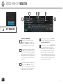
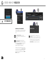
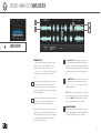
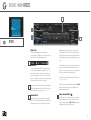
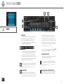
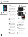
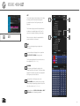
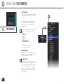
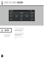
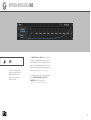
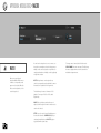
1
SOFTWARE USER MANUAL
SOFTWARE VERSION 1.0
EN151105
END USER LICENSE AGREEMENT [EULA]
Falcon (henceforth ‘the Product’) is licensed to you as
the end user. Please read this agreement carefully. You
cannot transfer ownership of these sounds and software
they contain. You cannot re-sell or copy the Product.
3. OWNERSHIP
As between you and UVI, ownership of, and title to, the
enclosed digitally recorded sounds (including any copies)
are held by UVI. Copies are provided to you only to
enable you to exercise your rights under the license.
LICENSE AND PROTECTION
4. TERM
1. LICENSE GRANT
UVI grants to you, subject to the following terms and
conditions, a non-exclusive, non-transferable right to use
each authorized copy of the Product.
The product is the property of UVI and is licensed to
you only for use as part of a musical performance, live or
recorded. This license expressly forbids resale or other
distribution of the sounds and software included in the
Product or their derivatives, either as they exist on disc,
reformatted for use in another digital sampler, or mixed,
combined, filtered, resynthesized or otherwise edited,
for use as sounds, multi-sounds, samples, multi-samples,
wavetables, programs or patches in a sampler, microchip
or any hardware or software sample playback device.
You cannot sell the Product content or give it away for
use by others in their sampling or sample playback
devices. In the event UVI terminates this agreement due
to your breach, you agree to return the original and all
other copies of the software and documentation to UVI.
UVI reserves all rights not expressly granted to herein.
This agreement is effective from the date you open this
package, and will remain in full force until termination.
This agreement will terminate if you break any of the
terms or conditions of this agreement. Upon termination
you agree to destroy and return to UVI all copies of this
product and accompanying documentation.
5. RESTRICTIONS
Except as expressly authorized in this agreement, you
may not rent, sell, lease, sub-license, distribute, transfer,
copy, reproduce, display, modify or time share the
enclosed product or documentation.
6. HARDWARE
Accompanying USB flash media is only guaranteed
in it’s original state, as an installation medium for the
Product. Any variance from this use including but not
limited to deleting, altering or adding data, reformatting
the media or any physical alteration of the device will
void its warranty. If the media is found to have a physical
or manufacturing defect please contact our support
department (http://www.uvi.net/contact-support).
2. PROTECTION OF SOFTWARE
You agree to take all reasonable steps to protect the
product and any accompanying documentation from
unauthorized copying or use. You agree not to modify
the product to circumvent any method or means adopted
or implemented by UVI to protect against or discourage
the unlicensed use of copying of the Product.
©2015 UVI. All rights reserved. All trademarks are the
property of their respective owners.
TABLE OF CONTENTS
INTRODUCTION������������������������������������������������������������������������ 4
APPENDIX A
SVF����������������������������������������������������������������������� 114
SIMPLE DELAY �������������������������������������������������� 155
SYSTEM REQUIREMENTS������������������������������������������������������5
SAMPLING OSCILLATORS���������������������������������������������71
UVI FILTER����������������������������������������������������������� 115
STEREO DELAY�������������������������������������������������� 156
INSTALLATION ��������������������������������������������������������������������������6
SAMPLE ����������������������������������������������������������������72
VOWEL FILTER ���������������������������������������������������116
GATE REVERB���������������������������������������������������� 157
STEP 1: REGISTER YOUR SERIAL NUMBER���������������� 7
SLICE����������������������������������������������������������������������73
WAHWAH������������������������������������������������������������� 117
PLAIN REVERB�������������������������������������������������� 158
STEP 2: ACTIVATE YOUR LICENSE������������������������������8
STRETCH��������������������������������������������������������������75
XPANDER FILTER����������������������������������������������� 118
PREDELAY REVERB������������������������������������������ 159
STEP 3: INSTALL FALCON����������������������������������������������9
IRCAM GRANULAR ��������������������������������������������76
3 BAND SHELF���������������������������������������������������119
SIMPLE REVERB������������������������������������������������160
STEP 4: AUDIO & MIDI DEVICES�������������������������������� 10
IRCAM MULTI GRANULAR��������������������������������78
8 BAND EQ �������������������������������������������������������� 120
AUTO WAH ��������������������������������������������������������� 161
STEP 5: ADDING SOUNDBANKS��������������������������������� 11
IRCAM SCRUB������������������������������������������������������79
BIG PI TONE�������������������������������������������������������� 121
FX FILTER������������������������������������������������������������ 162
STRUCTURE ���������������������������������������������������������������������������� 12
IRCAM STRETCH ����������������������������������������������� 80
CONVOLVER������������������������������������������������������ 122
TALKBOX������������������������������������������������������������ 163
COMPONENTS������������������������������������������������������������������������ 15
SYNTHESIS OSCILLATORS���������������������������������������� 81
TILT���������������������������������������������������������������������� 123
2 BAND EQ �������������������������������������������������������� 164
OSCILLATORS���������������������������������������������������������������� 16
ANALOG��������������������������������������������������������������� 82
TONE STACK������������������������������������������������������ 124
3 BAND EQ �������������������������������������������������������� 165
EFFECTS���������������������������������������������������������������������������17
ANALOG STACK��������������������������������������������������83
AUTOPAN����������������������������������������������������������� 125
ROTARY SIMPLE������������������������������������������������ 166
MODULATORS���������������������������������������������������������������� 18
DRUM��������������������������������������������������������������������84
GAIN�������������������������������������������������������������������� 126
ROTARY SPEAKER�������������������������������������������� 167
EVENT PROCESSORS �������������������������������������������������� 19
FM������������������������������������������������������������������������� 85
GAIN MATRIX ���������������������������������������������������� 127
COMPRESSOR �������������������������������������������������� 168
INTERFACE ����������������������������������������������������������������������������� 20
NOISE������������������������������������������������������������������� 86
TREMOLO ���������������������������������������������������������� 128
LIMITER��������������������������������������������������������������� 169
TOOLBAR������������������������������������������������������������������������ 21
ORGAN������������������������������������������������������������������87
UVI WIDE������������������������������������������������������������ 129
UVI MASTERING������������������������������������������������ 170
STATUS BAR��������������������������������������������������������������������23
PLUCK������������������������������������������������������������������� 88
ANALOG CRUNCH�������������������������������������������� 130
BEAT REPEAT ����������������������������������������������������� 171
MAIN
��������������������������������������������������������������������������������24
WAVETABLE ������������������������������������������������������� 90
DOUBLE DRIVE��������������������������������������������������� 131
RING MODULATOR ������������������������������������������ 172
EDIT������������������������������������������������������������������������25
EFFECTS ������������������������������������������������������������������������ 91
DRIVE������������������������������������������������������������������ 132
ROBOTIZER�������������������������������������������������������� 173
PROGRAM��������������������������������������������������27
ANALOG TAPE DELAY����������������������������������������92
EXCITER�������������������������������������������������������������� 133
UVI DESTRUCTOR���������������������������������������������174
LAYER ��������������������������������������������������������28
DUAL DELAY��������������������������������������������������������93
FUZZ�������������������������������������������������������������������� 134
KEYGROUP����������������������������������������������� 29
DIFFUSION ����������������������������������������������������������94
GUITAR BOXES�������������������������������������������������� 135
ARPEGGIATOR �������������������������������������������������� 176
OSCILLATOR��������������������������������������������� 30
IREVERB��������������������������������������������������������������� 95
OVERDRIVE�������������������������������������������������������� 136
MIDI PLAYER������������������������������������������������������ 178
MAPPING���������������������������������������������������� 31
SPARKVERB�������������������������������������������������������� 96
UVI DRIVE ���������������������������������������������������������� 137
MICRO TUNER �������������������������������������������������� 179
MODULATION ������������������������������������������35
ANALOG CHORUS����������������������������������������������97
WAVE SHAPER�������������������������������������������������� 138
SCRIPT PROCESSOR����������������������������������������180
EVENT PROCESSORS
MODULATORS
SAMPLE EDITOR ���������������������������������������41
ANALOG FLANGER������������������������������������������� 98
3 BAND COMPRESSOR������������������������������������ 139
EFFECTS ��������������������������������������������������������������44
CHORUS��������������������������������������������������������������� 99
3 BAND LIMITER������������������������������������������������ 140
AHD���������������������������������������������������������������������� 182
EVENTS ����������������������������������������������������������������46
CROSS PHASER������������������������������������������������100
COMPRESSOR EXPANDER ����������������������������� 141
ANALOG ADSR�������������������������������������������������� 183
MODS�������������������������������������������������������������������� 47
ENSEMBLE 505 �������������������������������������������������101
GATE�������������������������������������������������������������������� 142
ATTACK DECAY ������������������������������������������������ 184
INFO����������������������������������������������������������������������49
FLANGER������������������������������������������������������������ 102
MAXIMIZER�������������������������������������������������������� 143
DAHDSR�������������������������������������������������������������� 185
PARTS������������������������������������������������������������������� 50
PHASER�������������������������������������������������������������� 103
STUDIO LIMITER������������������������������������������������ 144
DRUNK���������������������������������������������������������������� 186
TREE����������������������������������������������������������������������52
ROTARY �������������������������������������������������������������� 104
PHASE METER �������������������������������������������������� 145
LFO���������������������������������������������������������������������� 187
LIST������������������������������������������������������������������������54
ANALOG FILTER������������������������������������������������105
SPECTRUM ANALYZER������������������������������������ 146
MACRO���������������������������������������������������������������� 188
FILE BROWSER����������������������������������������������������57
BIQUAD FILTER��������������������������������������������������106
TUNER ���������������������������������������������������������������� 147
MULTI ENVELOPE���������������������������������������������� 189
PRESET BROWSERS ����������������������������������������� 62
BRICKWALL FILTER ������������������������������������������ 107
EFFECTRACK ���������������������������������������������������� 148
STEP ENVELOPE ����������������������������������������������190
MIXER ������������������������������������������������������������������������������63
COMB FILTER ����������������������������������������������������108
REDUX ���������������������������������������������������������������� 149
APPENDIX B: SCRIPTING IN LUA �������������������������������������191
PERFORMANCE������������������������������������������������������������ 65
CROSSOVER FILTER ����������������������������������������109
UVINYL����������������������������������������������������������������150
LINKS���������������������������������������������������������������������������������������� 193
GENERAL CONVENTIONS ����������������������������������������� 66
LOWPASS 12 �������������������������������������������������������110
USER PRESETS������������������������������������������������������������������������67
LOWPASS 24�������������������������������������������������������� 111
FX DELAY������������������������������������������������������������ 152
PREFERENCES ����������������������������������������������������������������������� 69
ONE POLE����������������������������������������������������������� 112
FAT DELAY���������������������������������������������������������� 153
REZ FILTER����������������������������������������������������������� 113
LEGACY EFFECTS
PING PONG DELAY ������������������������������������������ 154
3
INTRODUCTION
FALCON
Falcon is multi-timbral hybrid instrument, bringing together an extensive collection of
oscillators, effects, modulators and event processors and delivering them in a workflowadaptive and highly-scriptable environment.
SYNTHESIS
Falcon offers 15 highly-optimized oscillators covering the spectrum of modern sampling
and synthesis techniques. Sample-based oscillators include IRCAM Granular, IRCAM Multi
Granular, IRCAM Scrub, IRCAM Stretch, Sample, Slice and Stretch. Synthesis oscillators
include Analog, Analog Stack, Drum, FM, Noise, Organ, Pluck and Wavetable.
EFFECTS
Over 80 high-quality effects are at your disposal, categorized for easy navigation: Delays,
Reverbs, Modulation, Filters, Equalizers, Amps and Stereo, Drive and Distortions, Dynamics,
Analysis and more. UVI’s rich heritage of effect design is in full force with sophisticated
delays, versatile reverbs (including the Sparkverb algorithm and a CPU-optimized
convolution reverb), compressors, vinyl, reamping effects and more. Add effects at the patch
level, as sends or even per note.
MODULATION
Rich sound means motion and Falcon can create it
whenever and however you need it. AHD, Analog
ADSR, Attack Decay, DAHDSR, Drunk, LFO, Multi
Envelope and Step Envelope modulation generators
all come standard and cv in the Falcon environment.
Create variation over time or on demand, drive your
oscillators, effects or even other modulators, then
add the most important parameters to the macro
panel for clear and intuitive performance control.
PERFORMANCE
Falcon was designed with a rich performance
toolset including full Open Sound Control (OSC)
implementation, host automation, flexible MIDI and
audio routing, MIDI learn, key range and velocity
range controls, keyswitching and more. Whether
you’re working with a single instrument or an
ensemble, in a DAW or standalone, Falcon gives
you the control you need to create dynamic and
captivating performances.
EVENTS
Falcon’s Event processors provide control and
analysis of the pre-synthesis phase of your sound,
from manipulating incoming MIDI data to creating
it algorithmically. Utilize factory processors such as
an advanced Arpeggiator, Micro Tuner, Chorder,
Harmonizer, Strum simulator, MIDI Player, Unison
and Shepard effects, or code your own from scratch
with the powerful Lua scripting language.
SOUNDS
Falcon comes with an incredible collection of
presets created by some of the world’s most
recognized sound designers, but there’s much
more to discover. Falcon is fully-compatible with all
UVI and UVI-Powered soundbanks, opening up a
world of over 200 instruments from a growing list of
companies like AcousticSamples, GospelMusicians,
VI Labs and VirHarmonics.
INTERFACE
From editing at the component level to mixing
and realtime performance of multiple instruments,
Falcon’s interface was designed to be both
ergonomic and adaptable. Due to the nature
of instrument design and interactive music
performance, projects can quickly become large
and multifaceted. Falcon’s UI was structured to help
mitigate that complexity and allow you to quickly
focus regardless of the level of detail.
SCRIPTING
Falcon implements custom scripts throughout its
architecture allowing you to create everything
from custom Event processors to professionallevel skinned instruments with the powerful and
lightweight Lua scripting language. Don’t know
anything about scripting? Don’t worry, Falcon has
a built-in visual editor for creating fully customized
macro-driven interfaces.
4
SYSTEM REQUIREMENTS
MAC OS
WINDOWS
LICENSE
COMPATIBILITY
COMPATIBILITY
AUTHORIZATION
•
•
•
•
• VST
• AAX
• Stand Alone
Your license allows for unlimited installation and up to 3
concurrent authorizations of Falcon on any combination
of computer hard drives or iLok dongles.
MINIMUM SYSTEM REQUIREMENTS
MINIMUM SYSTEM REQUIREMENTS
MANAGEMENT
•
•
•
•
•
•
•
•
•
•
License management is a simple drag-and-drop process
done through the free iLok License Manager client app.
Visit iLok.com to download the latest version or sign up
for a free account.
Audio Unit
VST
AAX
Stand Alone
Intel CPU
2 GB of RAM+
1 GB of Disk Space
MAC OS X 10.7+
iLok Account (Free)
Core 2 Duo or faster
2 GB of RAM+
1 GB of Disk Space
Windows 7+
iLok Account (Free)
5
INSTALLATION
INSTALLATION » STEP 1: REGISTER YOUR SERIAL NUMBER
REGISTER
• You must have an account on uvi.net
and ilok.com prior to registration
• Your serial number will be included in
a purchase confirmation email
• You can see a list of the products
you’ve registered and their serial
numbers anytime at uvi.net/myproducts
1. LOGIN TO YOUR ACCOUNT ON UVI.NET
2. NAVIGATE TO THE ‘PRODUCT REGISTRATION’ PAGE
3. ENTER YOUR DETAILS AND CLICK ‘REGISTER’
A new license will be deposited in your iLok account
7
INSTALLATION » STEP 2: ACTIVATE YOUR LICENSE
ACTIVATE
1. LAUNCH ILOK LICENSE MANAGER
• The iLok License Manager client app
is required for activation, download
the newest version at ilok.com
• Your license allows for up to 3
concurrent activations on any
combination of computer hard drives
or iLok dongles
• Activations can be moved between
devices freely, at any time
• To see how many authorizations you
have left simply select the license
in iLok License Manager and click
‘Show Details’
• To deactivate an authorization,
right-click it and select ‘Deactivate’.
This will return the license to the
‘Available’ tab.
2. LOGIN TO YOUR ACCOUNT
3. CLICK THE ‘AVAILABLE’ TAB
4. DRAG THE LICENSE TO A COMPUTER OR ILOK
5. CLICK ‘OK’ TO CONFIRM ACTIVATION
8
INSTALLATION » STEP 3: INSTALL FALCON
INSTALL
• You can download your products at
any time through uvi.net/my-products
1. DOWNLOAD YOUR SOFTWARE AT
UVI.NET/MY-PRODUCTS
2. RUN THE INSTALLER
9
INSTALLATION » STEP 4: AUDIO & MIDI DEVICES (STAND ALONE)
CONFIGURE I/O
If you plan to use Falcon in stand
alone mode you may need to select
which MIDI inputs and Audio outputs
you want Falcon to use. This only
needs to be done the first time
you launch Falcon, or if you make
changes to your hardware (such
as changing your audio interface
or controller keyboard), as these
settings will be saved and reloaded
the next time you start Falcon.
1. LAUNCH FALCON
2. SELECT ‘AUDIO AND MIDI SETTINGS...’ FROM THE MENU
3. SELECT THE DESIRED AUDIO AND MIDI DEVICES...
If you intend to use Falcon primarily
as a plugin you can skip this step, as
the audio and MIDI settings will be
defined by your host DAW.
AUDIO DEVICES
ROUTING
MIDI DEVICES
Select the desired audio interface, sample rate
and buffer size from the menus. If you don’t see
your device listed, make sure it’s powered on
and hit ‘Refresh Audio Devices’.
Falcon can address up to 17 stereo outputs.
Use this panel to link Falcon’s outputs with
those of your audio interface.
Falcon can listen to 4 MIDI devices. Use this
panel to link Falcon’s inputs with the MIDI
sources available on your system.
10
INSTALLATION » STEP 5: ADDING SOUNDBANKS (OPTIONAL)
LOAD SOUNDBANKS
UVI Powered soundbanks are highquality sound and instrument libraries
available from UVI and third-party
developers. Soundbanks are fully
supported and seamlessly integrated
in Falcon.
To use soundbanks in Falcon you
just need to tell it where to find them.
1. LAUNCH FALCON
2. OPEN ‘PREFERENCES’
NOTE: Falcon includes two
soundbanks (Falcon Factory.ufs,
and Falcon Tutorial.ufs), follow these
instructions to make them available
to Falcon.
3. CLICK THE ‘SOUNDBANKS’ PAGE
4. CLICK THE ‘...’ BUTTON AND SELECT THE FOLDER THAT CONTAINS YOUR SOUNDBANK (.UFS) FILES
5. RESTART FALCON, SOUNDBANKS WILL BE AVAILABLE IN THE BROWSER
11
STRUCTURE
STRUCTURE
Structure
Multi
Part
Program
Layer
Keygroup
Effects
Effects
Effects
Effects
Effects
Modulators
Modulators
Modulators
Modulators
Modulators
Events
Events
Events
Events
Events
Oscillators
File Management
Multi (.uvim)
Program (.uvip)
Control Signal Flow
Audio Signal Flow
FALCON is a hierarchy of components, structured
so that you can focus on the high-level arrangement
or drill down to deeper levels as you prefer.
Each instance of Falcon contains:
• one MULTI, which contains …
• one or more PARTS
Each of those PARTS then contains:
• one PROGRAM, which contains …
• one or more LAYERS, each which contains …
• one or more KEYGROUPS, each which contains …
• one or more OSCILLATORS
Each level of this hierarchy has a rich variety of
options for crafting your sound, using:
• MODULATION control signals, such as LFOs,
envelopes, and MIDI controllers
• AUDIO EFFECTS, such as filters, delays, and reverb
• MIDI EVENT PROCESSORS, such as arpeggiators,
micro tuners, and script processors
13
STRUCTURE
For example, a multi might contain two parts: a drum
loop and a grand piano. The drum loop could have
a single layer with a single keygroup, which contains
a single oscillator playing a single audio sample.
The grand piano program might contain three
layers, each of which contains dozens of keygroups
and audio samples, multiple envelopes and a script
processor, all passing through reverb, EQ, and a
multi-band compressor.
A single Pluck oscillator routed
into a spectrum analyzer
At its simplest, you can launch Falcon, load some
instruments or loops, and just begin playing without
worrying about how it’s all put together. At the other
end, you can craft from scratch your own multilayered and advanced programs containing dozens
or hundreds of oscillators with numerous modulation
sources, and then mix many instruments and loops
together using multiple parts and effects chains.
The sounds included with Falcon or with third-party
libraries contain highly-detailed and richly-varied
programs that don’t require any editing at all.
However, Falcon also provides the means to modify
and extend sounds, which can be peeled back one
layer at a time for increasingly detailed adjustments.
Dozens of keygroups, with
multiple sample oscillators and
effects each, represent just a
single layer of VI Labs exquisite
Ravenscroft Grand Piano
14
COMPONENTS
The basic components of Falcon are:
•
•
•
•
OSCILLATORS
EFFECTS
EVENT PROCESSORS
MODULATIONS
These components, described in the
following sections, can be combined
in near-infinite variations to produce
compelling sounds and instruments.
COMPONENTS » OSCILLATORS
OSCILLATORS
One of Falcon’s greatest strengths
is its ability to freely layer
oscillators to create elaborate
hybrid instruments that capitalize
on the unique features of both
sample-based and algorithmic
sound creation. There are no
preset limits on the quantity
or type of oscillators you can
use, you’re limited only by your
computers processing power
and imagination.
OSCILLATORS
An oscillator is the basic building block of a Falcon
program. Oscillators generate the initial sound, which
is then modulated, transformed, and combined with
other oscillators into a full program. An oscillator can
be one of two types: synthesis or sampling.
SYNTHESIS
Synthesis oscillators produce purely synthesized
sounds — no audio sample is triggered. The
synthesis oscillators provided are capable of a wide
variety of sounds, from classic virtual analog synths
to drum modeling to string synthesis.
A synthesis-type oscillator: Analog Stack
SAMPLING
Sampling oscillators play back an audio sample.
Each of the sampling oscillators is suited for
different types of audio samples and different
playback needs, from traditional pitch and speed
transposition to slicing drum loops to granular pitch
adjustments.
For in-depth details on each oscillator type, see:
[Appendix A > Oscillators]
A sampling-type oscillator: IRCAM Multi Granular
16
COMPONENTS » EFFECTS
EFFECTS
Falcon includes over 80 highquality effects, categorized for
easy navigation: Delays, Reverbs,
Modulation, Filters, Equalizers,
Amps and Stereo, Drive and
Distortions, Dynamics, Analysis
and more. With effects suited for
nearly every need from creative
mangling to precise sound
sculpting, mixing and analysis,
Falcon provides a tremendous
sound design facility.
EFFECTS
Effects are audio signal processors. This includes
classic effects such as filters, reverb, and delays,
to advanced analysis tools such phase meters
and spectrum analyzers. Effects can be added
independently at every level of the multi, from a
single keygroup up to the master output.
The Xpander Filter, one of the many Filter-type effects in Falcon
MULITFX
Multiple effects can be saved and recalled as a
group with a single Multi FX preset. This provides
a way for complex chains of effects to be recalled
instantly.
For more information on using effects, see:
[Interface > Main > Effects Tab]
For in-depth details on each effect type, see:
[Appendix A > Effects]
MultiFX are entire effect chains that can be saved and recalled as needed
17
COMPONENTS » MODULATORS
MODULATORS
A Multi Envelope modulator provides unlimited breakpoints with complex curve control and interpolation options
Falcon includes 8 modulation
generators including AHD, Analog
ADSR, Attack Decay, DAHDSR,
Drunk, LFO, Multi Envelope
and Step Envelope. Modulation
generators can be instanced at
any level in a patch allowing them
to control nearly any parameter, be
it on an oscillator, effect or even
on another modulator. This system
allows you to paint motion into
your sounds almost effortlessly,
from subtle variation over time to
complex on-demand sequences.
MODULATORS
EXTERNAL
Modulators are signal generators that modify a control’s
value. Modulators don’t affect the audio or MIDI signal
directly; rather, they adjust the values of Falcon’s
controls. There are two main categories of modulation
sources: internal and external.
External modulation sources originate beyond the Falcon
instance. External sources include MIDI messages,
such as continuous controllers (CCs), pitch bend,
velocity, aftertouch, and others. Some pre-defined
external sources are also available, such as sources that
randomize or alternate values.
INTERNAL
Internal modulation sources originate from within the
Falcon multi or program. This includes a variety of
different types of envelopes and LFOs, which can be
created at every level of Falcon’s hierarchy: master, part,
program, layer, and keygroup.
Additionally, when using Falcon as a plug-in, you can
assign a control to be linked to the host program’s
automation controls. Host automation extends Falcon’s
available modulation options by tapping into the host’s
modulation and automation capabilities as well.
Additionally, macros are a special type of internal
modulation. When a control is assigned to a macro, a
macro control appears on the Info tab. When the macro
control is adjusted, so is the control assigned to it. A
control can be assigned one-to-one to a macro, as a
shortcut for a commonly used control in the program, or
multiple controls can be assigned to a single macro, for
complex transformations of multiple controls by adjusting
a single knob or button.
For more information on using modulations, see:
[Interface > Main > Modulation Editor]
For in-depth details on each modulation type, see:
[Appendix A > Modulators]
18
COMPONENTS » EVENT PROCESSORS
EVENT PROCESSORS
Falcon’s Event section provides
control over pre-synthesis data,
namely the manipulation, analysis
or generation of MIDI. Event
processors can do anything from
arpeggiating incoming notes or
strumming them like a guitar to
applying micro tunings, playing
back MIDI files or creating
generative sequences.
EVENT PROCESSORS
Event processors are MIDI signal processors.
This includes well-known processors such as
arpeggiators and micro-tuners, to complex,
customized processing with the script processor.
SCRIPT PROCESSORS
Script Processors are a unique subset of Events
Processors which allow Falcon’s functionality to
be extended with the Lua language. Factory Script
Processors include the Chorder, Harmonizer,
Unison, Ensemble and many more. Load any Script
Processor and click the ‘Edit Script’ button to take a
look at how they work. Experiment with modifying
them or write your own, Script Processors provide
both an extremely powerful way to interact with
existing instruments and a sophisticated codedriven approach to sound design.
An advanced arpeggiator provides deep control over note sequences
For more information on event processors, see:
[Interface > Main > Events Tab]
For in-depth details on each event processor type,
see: [Appendix A > Events]
Falcon’s Script Processors provide a powerful way to create your own custom tools
19
INTERFACE
INTERFACE » TOOLBAR
1
2
3
4
5
TOOLBAR
The toolbar is displayed at the top
of the window and is always visible
in Main, Mixer, and Performance
views. Most controls in the toolbar
apply globally to the entire Falcon
instance.
1
MAIN MENU
The main toolbar menu contains commands for loading/
saving files and configuring Falcon. The menu is divided
into four sections; details about the commands in each
section can be found on the following:
• [User Presets]
• [Preferences]
• [Toolbar > Window size]
3
4
MULTI MANAGEMENT
2
The name of the CURRENT MULTI is displayed in the
toolbar. Double-clicking the name will open the multi
File Browser. For more information on loading multis,
see: [User Presets > Multis] and [Interface > Main > File
Browser].
The NEXT MULTI / PREVIOUS MULTI buttons load
the next or previous multi in the same directory as the
current multi. The Next button will also advance into
subdirectories and load the next multi there, if any.
CHANGING THE VIEW
The MAIN, MIXER, and PERF buttons change the
primary view of the Falcon window. See [Interface >
Main], [Interface > Mixer], and [Interface > Performance]
for more information.
The left and right sidebars can be individually hidden or
shown with the SHOW/HIDE SIDEBAR buttons. The left
sidebar displays the PARTS EDITOR, TREE EDITOR,
and LIST EDITOR; the right sidebar displays the PRESET
BROWSER.
NOTE: The left sidebar is displayed in Main view only. In
Mixer and Performance views, the left sidebar will not be
displayed even if the button is enabled.
5
TEMPO AND TRANSPORT CONTROLS
Falcon’s current TEMPO is displayed in the toolbar. You
can edit the tempo here as well, from 10 to 400 bpm,
by double-clicking to enter a value or by clicking and
dragging the value up and down. NOTE: When Sync To
Host is enabled, the Tempo cannot be edited manually.
21
INTERFACE » TOOLBAR
6
7
8
9
TOOLBAR
6
7
8
If you would like to tap to enter the tempo rather than
typing in a value, use the TAP button. For best results,
tap repeatedly at a consistent tempo.
Enabling SYNC TO HOST will cause Falcon to follow an
external tempo source — the host application’s tempo
when using Falcon as a plug-in inside a host application,
or MIDI Beat Clock when using Falcon as a standalone
application. Additionally, enabling AUTOPLAY will cause
Falcon to play and stop along with the host application.
When using Falcon as a standalone application, the
AutoPlay button is not displayed. For details on part
auto-play, see also [Interface > Main > Parts > Auto Play].
9
GLOBAL TUNE AND VOLUME
GLOBAL TUNE adjusts the tuning for all parts, using the
A above Middle C as a reference. Global Tune defaults to
440 Hz, and is adjustable from 420 Hz to 460 Hz.
GLOBAL VOLUME adjusts the output volume for the
Main Outs.
WINDOW SIZE
To adjust the size of the Falcon window, open the
Toolbar menu and choose Small size, Big Size, or Fit
screen size.
The PLAY and STOP buttons are used to manually start
and stop Falcon’s playback. When AutoPlay is enabled,
the Play and Stop buttons also activate to show the
current state of the host application’s transport.
22
INTERFACE » STATUS BAR
1
2
3
STATUS BAR
The status bar is displayed at
the bottom of the window and
provides quick, at-a-glance
information.
1
2
VERSION
The installed version of Falcon is displayed on the left
side of the status bar.
HOVER HELP
As you use Falcon, the center of the status bar displays
contextual help, such as “Global Volume” when hovering
over the output volume knob in the top toolbar, or
“Oscillator tune in semitones” when hovering over the
Oscillator module’s Coarse Tune knob.
3
PERFORMANCE SUMMARY
The right side of the status bar displays a performance
summary for the current multi:
• memory usage
• CPU usage
• number of voices currently playing
23
INTERFACE » MAIN
MAIN
The Main view is the primary view
for creating and editing parts in
Falcon, and the instruments and
samples that those parts contain.
Left Sidebar
Center Pane
Right Sidebar
The primary areas of the Main view are:
• The CENTER PANE, for viewing and editing parts
• The LEFT SIDEBAR, for additional part controls
• The RIGHT SIDEBAR, for browsing and loading samples
and presets
24
INTERFACE » MAIN » EDIT
2
1
EDIT
The Edit tab is the primary view for
editing a program.
...
THE EDIT TAB
The major sections within the Edit tab are:
1
2
PROGRAM
LAYER
KEYGROUP
OSCILLATOR
MAPPING EDITOR
MODULATION EDITOR
When a section is shown, it can also be collapsed or
expanded using the arrow to the left of the section name.
Double-clicking the section header also collapses or
expands the section.
The first four sections — Program, Layer, Keygroup,
Oscillator — form a hierarchy. That is, a program contains
layers, a layer contains keygroups, and a keygroup
contains oscillators. For more information on how these
pieces fit together, see [Structure].
Each section may be shown or hidden, using the
corresponding buttons in the upper-right toolbar.
25
INTERFACE » MAIN » EDIT
5
3
EDIT
4
6
3
4
5
Each of these four sections contains a Parameters view
which displays its controls, The section parameter view
can be shown or hidden by pressing the toggle in the
section header.
Other lanes can be shown or hidden for each section,
such as effects, event processors, or modulation sources.
These lanes can be toggled with the corresponding
buttons in the section header.
Each of these lanes is a condensed view of a
corresponding tab, displaying only the modules of
that type which are saved at that particular level of the
program hierarchy.
6
To add a new module to a lane, press the plus (+) button
to display a menu of available modules. Each module
displays a tab, and the module’s controls are shown or
hidden by selecting the tab’s name. The module can be
enabled or disabled with the POWER button on the left
of the tab, or deleted with the X button on the right of the
tab. Additionally, a press and hold on the module’s name
will display a preset browser menu to replace the existing
module with a different one.
NOTE: For the Effects and Event lane, the left-to-right
order indicates the signal flow. For the Modulations lane,
the order isn’t significant. For more information, see:
[Main > Modulations Tab].
26
INTERFACE » MAIN » EDIT » PROGRAM
2
3
4
5
1
EDIT » PROGRAM
THE PROGRAM EDITOR
1
2
3
GAIN and PAN set the output level and stereo
placement for the entire program. These are distinct from
the Part gain and pan settings, and are saved with the
program.
To choose whether samples in the program are streamed
from disk or not, set the STREAMING toggle. For more
details on streaming, see [Preferences > Streaming].
To transpose incoming MIDI to the program, adjust the
OCTAVE and SEMI settings.
4
5
POLYPHONY sets the default number of simultaneous
voices available for each layer in the program.
(To override this on individual layers, see [Custom
Polyphony] in the Layer section.)
Keeping polyphony as low as you can helps reduce
the processing power needed to play back the
program, especially if you have per-keygroup effects or
modulations. The NOTE POLYPHONY value sets the
maximum number of simultaneous triggers of the same
note. A setting of zero is a special value that indicates
UNLIMITED.
27
INTERFACE » MAIN » EDIT » LAYER
2
3
4
5
6
1
EDIT » LAYER
THE LAYER EDITOR
1
2
3
4
GAIN and PAN set the output level and stereo
placement for the selected layers.
PLAY MODE determines what happens when additional
notes are triggered while another note is held. In POLY
modes, multiple notes can be played at once, in MONO
modes only the last triggered note will be played.
Additionally, with POLY PORTAMENTO or MONO
PORTAMENTO there is a glide from the previous note
to the current one. The duration of the glide is set by
GLIDE TIME. PORTAMENTO MODE chooses whether
the time is always the same (Constant Time), or whether
the time is proportionally longer based on the spread
between the two notes (Proportional Time). In MONO
PORTAMENTO SLIDE mode, the next note always starts
from the pitch of the previous note and glides to the new
pitch, even if the next note is played after the previous
note is released.
UNISON VOICES sets the number of voices triggered
with each note received. When using multiple voices,
the Unison modulation sources (found under External >
Other) can be used to modulate parameters per voice,
such as Keygroup Pitch or Pan, for a dynamic sound.
5
6
CUSTOM POLYPHONY sets the maximum polyphony
for the layer. A setting of zero is a special value that
indicates that there is no layer-specific limit.
The VELOCITY CURVE sets the mapping of incoming
velocity values. The default is NORMAL (1:1 mapping).
To change the velocity curve, right-click and choose one
of the presets:
• CONSTANT: The same velocity is always triggered,
regardless of the incoming velocity. To set the value,
double-click and enter a velocity value.
• MAX: A constant velocity of 127
• HARD: Remapped so that higher velocities are triggered
• NORMAL: Default, 1:1 mapping
• SOFT: Remapped so that lower velocities are triggered
The curve displays incoming velocities on the X axis,
and triggered velocities on Y. For finer adjustment of the
velocity curve, hold the Shift key and drag the curve up
or down. You can also double-click and enter a value:
• Values between -1 and zero cover the range between the
Hard and Normal presets
• Values between zero and +1 cover the range between
the Normal and Soft presets
• Values between +1 and 127 set a constant velocity
28
INTERFACE » MAIN » EDIT » KEYGROUP
2
3
4
5
1
EDIT » KEYGROUP
THE KEYGROUP EDITOR
1
2
GAIN and PAN set the output level and stereo
placement for the selected keygroups.
TRIGGER MODE determines what event triggers the
keygroup to play back:
• ON: Keygroup is triggered by note on; this is the default.
• OFF: Keygroup is triggered by note off.
• OFF + E: Keygroup is triggered by note off, and the
current level of the amplitude envelope will be used as
the initial amplitude.
• OFF + V: Keygroup is triggered by note off, and the note
off velocity will be used as the initial amplitude.
• OFF + VE: Keygroup is triggered by note off, and both
note-off velocity and the amplitude envelope will be
applied to determine the initial amplitude.
Off + E, Off + V, and Off + VE modes are helpful for
matching the amplitude of a release sample with the
samples that preceded it.
3
• NEXT BAR: The keygroup is triggered at the beginning
of the next full bar
The Next Beat/Bar options are useful when triggering
keygroups with tempo-synced effects such as
arpeggiators, or a keygroup containing a tempo-synced
loop.
4
5
The EXCLUSIVE GROUP is a way of indicating
keygroups which should be mutually exclusive. The
classic use case is a group of hi-hat sounds, where a
closed hi-hat should cutoff any open hi-hat sounds.
There are 32 separate exclusive groups available per
layer. A setting of zero is a special value that indicates no
exclusive group assignment.
When LATCH is enabled, notes are held (or “latched on”)
indefinitely when they are triggered; to release the note,
play the same note again.
TRIGGER SYNC determines how the keygroup is played
back once triggered:
• IMMEDIATE: The keygroup is triggered immediately
• NEXT BEAT: The keygroup is triggered at the beginning
of the next full beat
29
INTERFACE » MAIN » EDIT » OSCILLATOR
2
3
4
5
1
EDIT » OSCILLATOR
THE OSCILLATOR EDITOR
1
2
3
4
A keygroup contains one or more oscillators. With EDIT
ALL OSCILLATORS enabled, the parameters described
below will be edited simultaneously for all oscillators in
the keygroup. To edit each oscillator individually, disable
Edit All Oscillators and select the desired oscillator tab.
The COARSE TUNE and FINE TUNE controls set the
oscillator’s pitch in semitones and cents. These controls
are for static adjustments, and cannot be modulated.
The PITCH control, however, can be modulated, and is
adjustable over a wide range (±4 octaves). Typical usage
might be: FINE TUNE to pitch-correct a sample that’s
slightly out of tune, COARSE TUNE to shift the pitch a
few keys up or down the keyboard, PITCH to modulate
the oscillator’s pitch with an LFO or envelope
GAIN and sets the output level for the selected
keygroups.
NOTE TRACKING determines how incoming notes are
transposed. At 100%, each note is transposed relative
to the root key 1:1. At 200%, transposition is double; for
example, if the root key is G4 and an G#4 is played, the
note will be transposed as if an A4 was played.
Negative values invert the transposition; for example, if
the root key is G4 and a G#4 is played, at -200% the note
will be transposed as if an F4 was played. For a constant
pitch regardless of the note triggered, use 0%.
5
If there are multiple oscillators in the keygroup, the
TRIGGER MODE chooses which will be triggered:
• ALL: All oscillators in the keygroup are triggered
simultaneously with every note.
• CYCLE: Oscillators are triggered individually, “round
robin” style. The first oscillator will be triggered on the
first note, the second oscillator with the second note, and
so on, always in the same order. With oscillators A, B,
and C, the order will always be A-B-C, A-B-C, etc.
• RANDOM CYCLE: Same as Cycle, but the order is
randomized within each cycle. Each oscillator will always
be triggered once per cycle. Additionally, the first note
of a cycle will never be the same as the last note of the
previous cycle, so there won’t be any direct repeats. With
oscillators A, B, and C, the order might be B-A-C, A-C-B,
then C-B-A.
• RANDOM: One random oscillator is triggered
individually. With oscillators A, B, and C, the order might
be A-C-C-B-A-B-B-C-A.
30
INTERFACE » MAIN » EDIT » MAPPING
3
2
1
EDIT » MAPPING
THE MAPPING EDITOR
The Mapping Editor displays the arrangement of the
program’s layers and keygroups. Programs can contain
anywhere from a single keygroup in a single layer
assigned to the entire key range and velocity range,
to many layers each with dozens of keygroups that are
assigned to very small ranges.
Above the piano keyboard, the key range is displayed
horizontally and the velocity range is displayed vertically.
Each keygroup appears as a block covering its key and
velocity range. When a program has multiple layers, the
layers are stacked on top of each other.
Pressing a key on the piano keyboard will trigger the
note; if a keygroup is assigned to that key, it will be
played back. Higher velocities are triggered by pressing
the key closer to the bottom; lower velocities are
triggered by pressing close to the top.
To adjust a keygroup’s key range or velocity range,
select the keygroup then click and drag any edge.
1
2
3
Hold the Command key (Mac) or Control key (Windows)
before you start dragging the keygroup edge to fade the
key or velocity range. The beginning of the fade will be
indicated by a dashed line within the keygroup.
The toolbar above the mapping area displays details
for the selected keygroup, such as its root key, key
range, velocity range, and more. These fields can all be
edited in the usual manner: double-clicking to enter text,
scrolling, and so on. You can also select and edit multiple
keygroups at once.
Additional commands are available under the menu,
available by pressing the menu button towards the left
end of the toolbar. TIP: The same menu is also available
by right-clicking in the mapping editor.
To view the mapping area in greater detail, zoom in or
out horizontally using the + and - buttons in the lower
right, or resize it vertically by dragging the Mapping
Editor toolbar up or down.
31
INTERFACE » MAIN » EDIT » MAPPING
5
4
EDIT » MAPPING
4
There are two additional options for helping navigate the
mapping editor: HIGHLIGHT PLAYED KEYGROUPS,
and MIDI SELECT. These options can be toggled on
or off with the buttons at the right end of the toolbar.
When Highlight played keygroups is enabled, keygroups
are visually highlighted as they are triggered. With MIDI
select enabled, keygroups are selected as they are
triggered.
To edit a keygroup, select one or more keygroups
then right-click to display a contextual menu of editing
commands (described below).
5
IMPORTING SAMPLES AS KEYGROUPS
Samples can be easily imported as keygroups by drag
and drop from the sidebar browser or your desktop.
You can drag a single sample, or multiple samples at
once. The vertical placement of the sample as you drop
it is a quick shortcut for the new keygroup’s key range
assignment — the closer you drop the sample to the top
of the velocity range, the larger key range the keygroup
will span.
Additionally, if you hold the Alt/Option key while dragging
in samples, a custom import dialog is displayed. Choose
the MAPPING METHOD, such as “NOTE NAME” or
“BLACK KEYS”, many of which determine details about
the sample from its file name or other metadata. The
selected mapping method displays a description with
details about how it will determine each file’s assignment.
The layer for the imported samples is chosen with
the DESTINATION LAYER selector. Samples can be
imported to one of the existing layers, or to a new layer.
32
INTERFACE » MAIN » EDIT » MAPPING
ADDING, MOVING AND DELETING KEYGROUPS
The Mapping Editor’s menu contains all of the edit
commands available in the Mapping Editor. To open the
menu, right-click anywhere in the Mapping Editor grid
or choose the menu button towards the left end of the
toolbar.
EDIT » MAPPING
Standard editing and selection commands are provided:
• CUT
• COPY
• PASTE
• DUPLICATE
• DELETE
• UNDO
• REDO
• SELECT ALL
• DESELECT ALL
• INVERT SELECTION
To move keygroups between specific layers, choose one
of the following and select a new or existing layer:
• PASTE KEYGROUP TO
• MOVE KEYGROUP TO
A new keygroup can be created, in the current layer or
a new layer. Choose one of the following, then choose
Sample or Synth:
• CREATE KEYGROUP
• CREATE KEYGROUP IN NEW LAYER
To copy the settings of one keygroup and apply them
to another keygroup, copy a keygroup, then select the
keygroup to be updated and choose Apply Keygroup
Template. This will replicate the same keygroup settings
(such as envelopes and other modulation sources)
without changing the oscillator type.
33
INTERFACE » MAIN » EDIT » MAPPING
EDIT » MAPPING
EDITING KEYGROUP RANGES
LAYER RULES
The EXTEND commands extend the keygroup’s range
in the chosen direction (right, left, top, or bottom) until
another keygroup boundary is encountered, or it reaches
the maximum value. The Auto Extend options are similar,
but extend in both directions: left and right for AUTO
EXTEND KEY RANGES, or top and bottom for AUTO
EXTEND VELOCITY RANGES. A keygroup can also be
reduced to only its root key, with AUTO REDUCE KEY
RANGES.
Layer Rules provide a way to
dynamically change how a
program’s layers are triggered.
For example, you might want
to switch between legato and
stacatto articulations, or cycle through multiple variations
of the same note to provide a more realistic performance.
Choose EDIT LAYER RULES from the Mapping Editor’s
menu to open the Layer Rules Editor.
For keygroups that overlap keys or velocities, choose
RESOLVE OVERLAPPING KEY RANGE or Resolve
Overlapping Velocity Range to adjust the ranges of
the keygroups so they no longer overlap. Alternatively,
the ranges of the keygroups can remain the same, but
key or velocity fades can be applied with AUTO FADE
OVERLAPPED KEYGROUPS.
The rules are displayed on the left, and a list of layers is
displayed on the right. First, right-click and add a ROOT
RULE. Next, right-click and add a SUB-RULE, one for
each layer or group of layers that you would like to be
affected by the rule. Then select each sub-rule, and
choose the desired layers from the list of target layers on
the right.
If you would like to simply change which keygroup is
displayed on top of the other, without adjusting their fade
or ranges, choose MOVE KEYGROUP TO FRONT or
MOVE KEYGROUP TO BACK.
Now choose a RULE TYPE for the root rule, such as
Key Switch. Each sub-rule can now be assigned to the
specific criteria which will trigger that layer. For example,
with a Key Switch rule and two sub-rules, the first subrule might be assigned to C0 and the second to D0.
KEYGROUP SAMPLES
For keygroups with sampling oscillators, it can be helpful
to use the SET KEYGROUP NAME AS SAMPLE NAME
command to give the keygroups more meaningful names.
The rule types are:
Key Switch, Pitch Bend, Speed, Note Duration, Cycle,
Random, Legato, Random Cycle, MIDI CC
If a program’s samples can’t be located, the samples will
be marked as missing. SELECT MISSING SAMPLES
will select any keygroup that contains an oscillator with
a missing sample; FIND MISSING SAMPLES checks for
missing samples and displays an error window listing any
missing files. From there, you can choose to ignore the
missing samples, or open the file browser to locate them.
Sub-rules can be added to sub-rules, to create further
branches in the layer triggering logic.
TIP: Falcon’s Script Processor module can also be used
to dynamically change playback styles. For more details,
see [Appendix B: Scripting in Lua].
34
INTERFACE » MAIN » EDIT » MODULATION
1
4
2
3
EDIT » MODULATION
THE MODULATION EDITOR
The Modulation Editor displays modulation assignments
and sources and is the central location for editing
modulation generators.
1
2
3
4
When you select a parameter, the node and name of
the parameter is displayed in the Modulation Editor.
For example, when the layer gain knob is selected, the
Modulation Editor displays “Layer > Volume”.
The top half of the Modulation Editor displays any
MODULATION ASSIGNMENTS for the selected
parameter.
The bottom half of the panel displays a MODULATION
SOURCE EDITOR for the selected modulation source.
The modulation source editor can be shown or hidden
with the button on the right side of the Modulation Editor
header.
UNDERSTANDING MODULATION SOURCES
A modulation source generates a control signal that is
used to modify other controls — on its own, it doesn’t
directly affect Falcon’s output. A modulation source
must be assigned to modulate another control to have
an effect. The location in Falcon’s hierarchy where you
create the modulation source determines its availability
as an assignment choice.
Modulation data flows from the top (Master level), down
through Part, Program, Layer and Keygroup levels to the
bottom (Oscillators). Therefor, a modulation generator
instanced at the Master level can target any parameter
within a given Falcon instance, and conversely a
modulation generator instanced at the Keygroup level
can only see target parameters within its own Keygroup.
NOTE: Master and part modulation sources aren’t
recommended to be assigned to program, layer, or
keygroup controls as programs can be saved and
recalled separately from the containing multi, and could
result in missing modulation sources. If you work with any
modules instanced above the Program level make sure
that you save your work as a Multi (.uvim) file in order to
maintain the integrity of your patch. For more information
on signal flow in Falcon see [Structure].
35
INTERFACE » MAIN » EDIT » MODULATION
6
7
8
9
5
5
EDIT » MODULATION
MODULATION ASSIGNMENTS
5
6
7
A parameter can have any number of modulation
assignments. Each assignment can be enabled or
disabled with the POWER button on the left of the tab,
or deleted with the X button on the right of the tab.
Each assignment displays the node, name, and type of
the modulation source. For example, with a keygroup
DAHDSR envelope named “Amp. Env,” the assignment
will display “Keygroup > Amp. Env [DAHDSR]”. To choose
a different modulation source for the assignment, press
and hold on the name and choose a different source
from the menu.
8
9
To further adjust the range, you can toggle INVERT to
flip the range, or make detailed, custom shapes with the
MODULATION MAPPER EDITOR.
Each modulation source also has a SUB-MODULATION
source that modulations the depth of the primary
modulation source signal. The sub-modulation source
can be enabled/disabled, removed, replaced, and its
ratio edited the same as for the primary modulation
source. One example would be an LFO assigned to an
oscillator’s pitch for vibrato, and the mod wheel assigned
as a subsource; the mod wheel would then be used to
dynamically set the depth of the vibrato.
The amount that the modulation source will affect the
parameter is set by the RATIO slider. The range is
displayed as +1 to -1 for most parameters, which can also
be thought of as +100% and -100%. For pitch-related
parameters, the range is +48 to -48 semitones.
36
INTERFACE » MAIN » EDIT » MODULATION
10
11
12
13
EDIT » MODULATION
14
15
10
MODULATION MAPPER EDITOR
The modulation mapper editor sits between the
modulation source and the parameter that it’s
modulating, remapping the values of the control
signal according to the mapper shape.
When no mapper is chosen, the modulation source
is mapped to parameter with a basic 1:1 relationship,
visualized as a linear ramp from the lowest value
to the highest value.
11
12
To enable a mapper, choose an existing mapper from the
MAPPER SELECTOR MENU or press the ADD button to
create a new one. You can also LOAD and SAVE preset
files from disk, as well as RENAME or DELETE them.
13
14
15
Create the mapper shape by clicking and dragging in the
graph; hold the Alt/Option key to draw a straight line. You
can also right-click and choose from a number of preset
shapes and functions.
When INTERPOLATED is enabled, the mapper
transitions smoothly from one value to the next; when
disabled, it transitions immediately from one value to the
next, which can create a stair-stepped effect.
Enabling INTEGER OUTPUT further constrains the
values output by the mapper to integer values only.
To set the size of the graph, set the horizontal axis with
the SIZE value and the vertical axis with RANGE.
37
INTERFACE » MAIN » EDIT » MODULATION
16
17
EDIT » MODULATION
MODULATION SOURCE EDITOR
The Modulation source editor displays the parameters of
the selected modulation source or sub-source.
16
The specific parameters shown for each modulation
source are described in detail in [Appendix A: Modules >
Modulators], and general use of modulation modules is
described in [Interface > Main > Modulations Tab].
The modulation source editor displayed here has a few
additional controls for helping navigate between different
modulation sources.
17
Directly above the modulation sources controls is a
navigation strip displaying the available modulation
sources for the selected parameter. The modulation
sources are displayed in a scrollable horizontal strip,
with icons separating the sections that they belong
to. You can also add new modulation sources to each
section, using its + button.
For modulation generators that support TEMPO SYNC
there is a small metronome icon in the toolbar. To enable
tempo sync simply toggle it on.
38
INTERFACE » MAIN » EDIT » MODULATION
18
19
EDIT » MODULATION
20
MAKING MODULATION ASSIGNMENTS
To assign a modulation source, right-click the parameter
that you would like to modulate and choose from the
menu.
18
19
Choose ADD MODULATION to create a new
assignment, using either an existing modulation source
or a new one.
To edit existing modulation connections, choose
EDIT MODULATIONS to view the parameters current
assignments in a pop-up directly next to the parameter.
Choose CLEAR MODULATIONS to remove all
modulation assignments for that parameter.
20
To quickly assign an MIDI CC to a parameter, choose
MIDI LEARN. You can then choose a MIDI CC from the
on-screen menu, or send the desired MIDI CC from your
MIDI keyboard controller. To remove the assignment,
choose Clear from the MIDI Learn window, or choose
MIDI UNLEARN from the modulation context menu.
Parameters can also be assigned to macros, for quick
control from the Info Tab. Choose ASSIGN TO MACRO
and assign one of the existing macros, or create a
new one. To remove the assignment, choose DELETE
MACROS assignment.
39
INTERFACE » MAIN » EDIT » MODULATION
AUTOMATION ASSIGNMENTS
HOST AUTOMATION
If you are using Falcon as a plug-in and would like
to control a parameter with your host application’s
automation tools, choose ASSIGN TO HOST
AUTOMATION and assign one of Falcon’s 128 host
automation controllers. To remove the assignment,
choose UNASSIGN HOST AUTOMATION.
EDIT » MODULATION
A limited number of parameters can be automated
externally, but not modulated. For those, right-clicking
the parameter will open the MIDI/AUTOMATION
CONTROL dialog, where a MIDI or host automation
source can be assigned.
OSC (OPEN SOUND CONTROL)
Finally, if you would like to control a parameter
externally with Open Sound Control, the parameter’s
OSC path is displayed in the menu. The path can also
be copied to the clipboard for easy assignment in
another application.
40
INTERFACE » MAIN » EDIT » SAMPLE EDITOR
2
4
5
3
1
SAMPLE EDITOR
SAMPLE EDITOR
For sample-based oscillator types, the Sample Editor
displays a waveform editor and additional controls
specific to audio files and loops. (See [Appendix >
Oscillators > Synthesis] for details on the editor controls
available for each of the synthesis-based oscillator
types.)
1
2
The Sample Editor’s primary display is the waveform of
the loaded audio sample. If the oscillator doesn’t yet
have a sample loaded, you can load one by drag and
drop from the sidebar file browser or the Finder (Mac) /
File Explorer (Windows).
3
4
The PARAMETERS button shows or hides the oscillator
parameters that are unique for that oscillator type. See
[Appendix > Oscillators > Sampling] for details on each
sampling oscillator type.
NOTE: Some of the sampling oscillators have a partial
subset of the full set of sample editing options described
below. The SAMPLE oscillator module has the largest
variety of sample editing operations available.
The time ruler above the waveform displays the duration
of the sample. To change the time format between
Samples, Beats, or Seconds, right-click the ruler.
By default the sample’s waveform is zoomed to fit the
display. To zoom in horizontally, hold the Alt/Option key
while scrolling with your mouse scroll wheel or trackpad
scroll gesture. Holding the Shift key while scrolling
zooms the waveform vertically.
The SAMPLE INFO button displays an overlay on top
of the sample waveform with details about the loaded
sample: the sample file location, bit depth, sample rate,
number of channels, duration, and file size. If the sample
is looped, details about the file’s loop are displayed as
well.
5
SAMPLE START/END
When a sample is loaded, you can adjust the points
where sample playback begins and ends within the file
by clicking and dragging the “S” and “E” markers.
41
INTERFACE » MAIN » EDIT » SAMPLE EDITOR
6
7
SAMPLE EDITOR
6
EDITING
LOOPING
To edit the sample file, click and drag to select a time
range for editing, then right-click to display a contextual
menu of editing commands.
Sample files can be played back and looped in a number
of ways.
Standard editing and selection commands are provided:
CUT. COPY, PASTE, UNDO, REDO, SELECT ALL,
DESELECT ALL
Common sample editing commands are also provided:
CROP, DELETE, NORMALIZE, SILENCE, REVERSE,
FADE IN, FADE OUT, PLAY SELECTION
7
Choose CHANGE PLAYING DIRECTION TO REVERSE
to simply play the sample in reverse; choose CHANGE
PLAYING DIRECTION TO FORWARD to change it back.
Choose SET AS ONE SHOT to play back a sample in
its entirety each time it is triggered, regardless of the
keygroup’s amplitude envelope. This is a natural fit for
drum and percussion samples. Choose DISABLE ONE
SHOT to return to standard playback.
APPLYING EFFECTS
You can also permanently apply Falcon’s audio effects to
a sample file. Select some audio and choose APPLY FX
from the contextual menu, and choose the desired effect.
Set the effect parameters, then press OK to apply.
If you would like to make the effect permanent,
remember to save the sample file. If not, choose Undo.
To add a loop to the sample, make a selection in the
sample. Then choose CREATE LOOP and pick one of
the loop types:
• FORWARD LOOP: The looped section is played forward;
when playback reaches the end of the loop, playback
begins again from the loop start point.
• ALTERNATE LOOP: The looped section is played
alternately forward (from the loop start to loop end) and
reverse (from loop end to loop start).
42
INTERFACE » MAIN » EDIT » SAMPLE EDITOR
10
8
9
SAMPLE EDITOR
8
9
Once a loop is created, you can adjust the points where
the loop begins and ends within the file by clicking and
dragging the L and R markers.
You can also choose to crossfade the looped section.
This can sometimes help make a loop sound less looped.
Choose ENABLE XFADE to enable loop crossfade, or
DISABLE XFADE to disable it. When the loop crossfade
is enabled, you can adjust the loop crossfade point with
the X marker.
When a sample has a loop and a note triggering the
sample is released, there are two release playback
options:
• ENABLE LOOPED RELEASE: Sample playback will loop
in the looped section until the release phase is over.
• DISABLE LOOPED RELEASE: Sample playback will
continue past the loop end marker until the release
phase is over or the sample end marker is reached,
whichever comes first.
Lastly, to remove the loop, choose DELETE LOOP.
10
SAVING
The standard module preset browser controls are also
displayed (see [Module Preset Browser]). The Preset File
menu also displays these options specific to sampling
oscillators.
• SAVE PRESET: Saves the oscillator parameters
• SAVE SAMPLE: Saves the sample/file in place
• SAVE SAMPLE AS…: Saves the sample to a new file
• SAVE SAMPLE WITH PLAYBACK OPTIONS: Saves the
sample/file in place and writes the sample and loop start/
end markers to the file
• SAVE SAMPLE AS WITH PLAYBACK OPTIONS…:
Saves the current sample to a new file and writes the
sample and loop start/end markers to the file
To reveal the sample file’s location, right-click the sample
and choose REVEAL IN FINDER (Mac) / REVEAL IN
EXPLORER (Windows) from the contextual menu.
BATCH EDITING
When multiple keygroups are selected, the Batch
menu appears. From the Batch menu, you can apply an
action to all of the selected keygroups at once, such as
normalizing samples or applying FX.
43
INTERFACE » MAIN » EFFECTS
4
1
2
3
EFFECTS
EFFECTS TAB
TIP: Keygroup effects are per voice. The more voices
you play back, the more effects processing power your
computer will need. Keygroup effects are best suited for
effects that you want to be processed distinctly for each
voice.
The Effects tab displays all of the audio effects
processing paths, from the effects on the master output
down to effects on an individual keygroup.
1
The signal flow is top to bottom. To reorder effects, press
and hold on an effect’s header and drag it to the new
position. To replace an effect, press on the effect’s name
and choose a different effect from the menu.
NAVIGATION
To choose which effects path you are viewing, choose
a node from the navigation breadcrumbs. Press on a
node’s name to show its effects. You can also press on
the arrow to the right of a node to view one of its child
nodes. For example, you can press the arrow to the right
of Program and choose from one of its layers.
2
3
For details on each of the effects included in Falcon, see
[Appendix A > Effects].
Each effect can be enabled or disabled with the POWER
button to the left of its name, or deleted with the X
button at the far right end.
You can also select a node in the Tree view sidebar, and
the Effects tab will show the selected node’s effects. For
more details on the Tree view, see [Interface > Tree].
ADDING EFFECTS
To add an effect, press the + button in the upper right
and choose an effect from the menu. You can also drag
and drop effects from the Preset Browser on the right.
4
TEMPO-SYNCING EFFECTS
Some effects, such as delay or tremolo, can sync their
time-based parameters to Falcon’s tempo. If an effect
supports tempo-syncing, a TEMPO SYNC toggle button
will appear next to the Preset File menu.
44
INTERFACE » MAIN » EFFECTS
10
7
8
9
5
6
EFFECTS
5
6
7
SAVING FX PRESETS
• The program aux FX are fed by sends on each layer and
keygroup in the program. These settings are saved in the
program.
Each effects module has a preset browser for saving,
recalling, and browsing presets for that effect type.
To save an effect preset, press the Preset File menu,
choose Save Preset, and name the preset. For more
details on the preset browser, see [User Presets >
Module Preset Browser].
MULTI FX
Multiple effects can also be saved and recalled as a
group with a Multi FX preset. This provides a way for
complex chains of effects to be recalled instantly. Multi
FX presets are saved and loaded through the Multi FX
preset menu. All effects for the current node can be
enabled or disabled together with the POWER button
to the left of its name. To clear all effects for the node,
choose Clear Multi from the Multi FX preset browser.
8
9
To adjust the aux sends to each of the aux busses, show
the aux FX nodes in the Tree view. On each node where
aux sends are present, you can set the send level, mute/
unmute the send, and toggle the send between pre/post
fader. For more details on the Tree view, see [Interface >
Tree].
You can also view the master aux FX and their sends
in the Mixer view. For more details on the Mixer, see
[Interface > Mixer].
AUX FX
There are two aux effects sections: master aux FX and
program aux FX.
• The master aux FX are fed by sends on each part in
the multi. These settings are saved in the multi.
To view and add aux FX in the Effects tab, choose the
aux bus from the navigation menu on the Part or Layer
nodes. Each aux effects section has four independent
aux busses.
10
MODULATION AND KEYBOARD SECTIONS
The Modulation and Keyboard sections can be toggled
in the Effects tab, using the buttons in the top right.
45
INTERFACE » MAIN » EVENTS
4
5
1
2
3
EVENTS
EVENTS TAB
The Events tab displays all of the MIDI event processing
paths, from master event processors down to event
processors on an individual layer. (Event processors
are not added to keygroups, as they generally address
events that span multiple keygroups.)
The signal flow is top to bottom. To reorder event
processors, press and hold on an event processors’s
header and drag it to the new position. To replace an
event processors, press on the event processors’s name
and choose a different event processor from the menu.
For details on each of the event processors included in
Falcon, see [Appendix A > Event Processors].
NAVIGATION
Event processors can be toggled on/off with the POWER
button or deleted with the X button in their toolbar.
1
To choose which event processing path you are viewing,
choose a node from the navigation breadcrumbs. Press
on a node’s name to show its events. You can also press
on the arrow to the right of a node to view one of its child
nodes. For example, you can press the arrow to the right
of Program and choose from one of its layers.
2
3
You can also select a node in the Tree view sidebar, and
the Events tab will show the selected node’s events. For
more details on the Tree view, see [Interface > Tree].
ADDING EVENTS
To add an event processor, press the + button in the
upper right and choose one from the menu. You can also
drag and drop them from the Preset Browser on the right.
SAVING EVENT PRESETS
Each event processor module has a preset browser for
saving, recalling, and browsing presets.
4
5
To save an event processor preset, press the Preset
File menu and choose Save Preset. For more details on
the preset browser, see [User Presets > Module Preset
Browser].
MODULATION AND KEYBOARD SECTIONS
The Modulation and Keyboard sections can be toggled
in the Events tab, using the buttons in the top right.
46
INTERFACE » MAIN » MODS
1
2
3
MODS
MODULATIONS TAB
The Modulations (Mods) tab displays all of the modulation
sources, from master modulation sources down to
modulation sources for a single keygroup.
1
NAVIGATION
To choose which modulation sources you are viewing,
choose a node from the navigation breadcrumbs. Press
on a node’s name to show its modulation sources. You
can also press on the arrow to the right of a node to view
one of its child nodes.
2
3
You can also select a node in the Tree view sidebar,
and the Modulations tab will show the selected node’s
modulation sources. For more details on the Tree view,
see [Interface > Tree].
ADDING MODULATION SOURCES
To add a modulation source, press the + button in the
upper right and choose a modulation sources from the
menu. You can also drag and drop modulation sources
from the Preset Browser on the right.
TIP: Keygroup modulations are per voice. The more
voices you play back, the more processing power your
computer will need. Keygroup modulations are best
suited for parameters that you want to be modulated
distinctly for each voice.
NOTE: Unlike Effects and Events, the list of modulation
sources doesn’t have a top-to-bottom signal flow. Until
a modulation source is assigned to modulate other
controls, it won’t have an effect on the signal flow. See
[Interface > Main > Modulation Editor] for more details.
To replace a modulation, press on the modulation’s name
and choose a different modulation from the menu.
For details on each of the modulation sources included in
Falcon, see [Appendix A > Modulators].
Each modulation source can be enabled or disabled with
the POWER button to the left of its name, or deleted with
the X button at the far right end.
47
INTERFACE » MAIN » MODS
SAVING MODULATION PRESETS
Each modulation module has a preset browser for
saving, recalling, and browsing presets for that specific
modulation type.
4
MODS
5
6
To save a modulation preset, press the Preset File
button, choose Save Preset, and name the preset. For
more details on the preset browser, see [User Presets >
Module Preset Browser].
4
RENAMING A MODULATION SOURCE
To rename a modulation source, double-click its name.
Using a descriptive name can help differentiate between
modulation sources of the same type (“Amp. Env.” and
“Filter Env.” for example).
ASSIGNING A MODULATION SOURCE
To assign a modulation source, right-click a control
and choose from the Add Modulation menu. Existing
modulation sources are listed first, or you can choose to
create a new modulation source on the spot.
For more information on modulation assignments, see
[Interface > Main > Modulation Editor].
7
7
5
6
MODULATION AND KEYBOARD SECTIONS
The Modulation and Keyboard sections can be shown or
hidden in the Modulations tab, using the buttons in the
top right.
48
INTERFACE » MAIN » INFO
INFO TAB
1
INFO
2
3
4
The Info tab provides an overview of the selected
program, houses macro controls, and provides a location
for custom text and images via. the (I) view.
2
MACROS
3
If macros have been assigned in the program they will
appear here. Macros are useful for placing important
controls on the “front panel” of a program.
To change the layout of the macro controls, press the
EDIT button in the upper left to switch to Edit Mode. You
can press and drag a control to move it, double-click a
label to rename it, or right-click and use one of the edit
commands from the contextual menu. For more details
on macros, see [Appendix A > Modulations > Macros].
PROGRAM INFORMATION
Press the (I) button in the upper right to display program
information. Many factory presets will contain details
about the program such as modwheel assignments,
macro descriptions or tips for playing it. You can add and
save descriptions for your own programs as well.
Programs in UVI soundbanks also display an image for
the program. If multiple images are present, “<” and “>”
arrows will be displayed and pressing them will cycle
through the images.
KEYBOARD
At the bottom of the Info tab, a keyboard is displayed and
can be clicked to play the program. The key range of the
program is highlighted, with keys outside the key range
darkened. If keyswitch layer rules have been created,
those keys are highlighted blue. Additionally, key color
can be customized using the Script Processor. For more
details on keyswitches, see [Interface > Main > Mapping
Editor > Layer Rules].
1
4
SCRIPT INTERFACE
If the program contains a script that defines a custom
user interface, the script interface will be displayed by
default. To toggle between the script interface and the
standard interface, use the Script button at the top of the
Info tab.
49
INTERFACE » MAIN » PARTS
PARTS
The Parts List displays a list view for managing and
editing all of the parts in Falcon, and for selecting a part
to be displayed and edited in the center pane.
2
4
3
The Parts List is displayed in the left sidebar, which can
be hidden or shown with its button in the Toolbar.
PARTS
1
To resize the Parts List width, click and drag on its right
edge. As the Parts List widens, the controls rearrange to
allow for greater numbers of parts to be viewed at once.
MANAGING PARTS
When a part is selected in the Parts List, it will be
displayed in the Main view’s center pane for editing.
Press anywhere on the part to select it.
The Parts List menu at the top left of the Parts List has
additional options for the selected part:
• Empty selected part
• Load program in selected part
• New program in selected part
2
3
4
1
To add or remove parts, use the + and - buttons next
to the Parts List menu. To reorder parts, press and hold
anywhere on the part and drag it to the new position.
MULTI CONTROLS
This section displays global controls for the Falcon multi.
The name of the currently loaded multi is displayed.
To load a different multi, double-click the name to open
the file browser, or use the next and previous buttons to
browse multis in the same directory.
The GLOBAL VOLUME and GLOBAL TUNE are also
displayed; see [Toolbar > Global Volume] and [Toolbar >
Global Tune] for details. OUTPUT METERS display the
audio levels for the Main Out output.
50
INTERFACE » MAIN » PARTS
PARTS LIST
5
The Parts List displays controls for each of Falcon’s parts.
Each of these settings are independent from the settings
saved in the program loaded in the part. These part
settings are saved and recalled with the multi (or your
host session if you’re using Falcon as a plug-in).
5
PARTS
The program name of the currently loaded program is
displayed. If there are unsaved changes, an asterisk will
appear next to the name, for example, “Love 1”.
6
7
9
12
To load a different program, double-click the name to
open the [File Browser], or Shift-double-click to open the
righthand sidebar [Preset Browser]. In either case, the
browser will be opened to the location of the currently
loaded program.
6
7
8
9
8
10
You can also use the next and previous buttons to
browse files in the same directory, or right-click and
choose an option from the contextual menu:
Empty part, Delete part, Load program, Reload program,
New program
The MIDI INPUT and AUDIO OUTPUT assignments
are displayed for each part. By default, each new
part is assigned to the Main Out, and its MIDI input is
incremented (A1, A2, A3, …). To change the assignment,
press and hold and choose from the menu. If the MIDI
assignment is set to Omni, it will listen for MIDI input on
all ports and all channels, and display an asterisk.
Option-click a mute or solo button to mute or solo only
that channel; Command-click (Mac) or Control-click
(Windows) to mute or solo all channels except the one
you clicked.
10
11
OUTPUT METERS display audio levels for the part’s
output. Also, whenever a part receives MIDI on its
assigned input channel, the MIDI input indicator flashes.
VOL and PAN controls set the output level and stereo
placement for the part. Each part also has MUTE and
SOLO buttons to mute or solo the part’s output. Alt/
11
12
The OCTAVE and SEMI controls transpose the part’s
incoming MIDI, in octaves and semitones.
If a loop is loaded in the part, two additional controls are
displayed:
• AUTO PLAY: When enabled, the loop will be triggered
when Falcon’s playback begins.
• PLAY: Highlights when the loop is playing, and can also
be used to manually start/stop loop playback.
The part’s color is displayed on the right side. To change
its color, click on the color bar and choose a color from
the color picker.
51
INTERFACE » MAIN » TREE
TREE
The Tree view displays a hierarchical view of a single
part, with each branch on the tree displayed as a “node”.
1
2
The Tree view contains two major sections:
INSTRUMENT, which displays the structure of the
nodes, and INSPECTOR, which displays details about
the selected node. The Tree view is displayed in the left
sidebar, which can be hidden or shown with its button in
the Toolbar.
TREE
3
The Inspector and Instrument sections can be collapsed
or expanded with the arrow to the left of the section
name. Additionally, the height of the Inspector section
can be adjusted by dragging its top edge.
1
2
INSTRUMENT
The Instrument section displays the nodes for a single
part, as well as a few global nodes. To choose which
part is displayed, choose the desired part from the PART
SELECTOR MENU in the upper right.
To choose which nodes are shown or hidden in the
Inspector, use the buttons in the upper right to toggle
these node types: Effects, Event Processors, Modulation
Sources, Aux FX busses and sends
Some node types are always displayed and cannot be
hidden: Master, Host Automation, Part, Program, Layer,
Keygroup, Oscillator
3
NAVIGATING WITH TREE VIEW
To navigate the nodes, press a node to select it and view
its details in the Inspector. Press the arrow to the left of
a node name to expand or collapse it. Holding the Alt/
Option key while expanding a node will expand all of its
children nodes as well.
52
INTERFACE » MAIN » TREE
The selected node in the Tree view also updates
navigation in Falcon’s other views, such as the Edit view,
Effects Tab, and so on. Using the Tree view to navigate
layers, keygroups, effects, and modulation assignments
can be very helpful in a large, complex program.
Double-clicking a node will jump to that node’s primary
edit view. For example, double-clicking an effect will
reveal it in the Effects Tab, and double-clicking a
modulation source will reveal it in the Mods Tab.
TREE
4
4
5
NODE OPTIONS
To see a menu of options available for a particular node,
select it and choose the menu icon in the upper left, or
right-click the node.
INSPECTOR
The Inspector displays details about the node that is
selected above in the Instrument section.
For properties that can be edited, double-click the value
to type in a new value, or click-drag the value up/down.
TIP: Most properties are also displayed in other views
such as the Edit view or Mixer, but there are some
“under-the-hood” properties displayed only in the
Inspector.
5
53
INTERFACE » MAIN » LIST
LIST
The List view displays a detailed rundown of the settings
for a single part and its currently-loaded program.
It contains four sections: Part, Program, Layers, and
Keygroups.
1
The List view is displayed in the left sidebar, which can
be hidden or shown with its button in the Toolbar. To
resize the List view width, click/drag on its right edge.
LIST
Each section can be collapsed or expanded with the
arrow to the left of the section name.
1
2
2
4
3
5
PART
The Part section displays the part settings for the
selected part.
To choose which part is displayed, choose a part from
the PART SELECTOR MENU in the upper right.
The Part settings displayed in List view are the same as
those displayed in [Interface > Parts].
3
4
5
PROGRAM
The Program section displays the settings for the
program loaded in the chosen part. The Program settings
displayed in List view are the same as those displayed in
the Program section in the Edit view.
On the right side of the Program section is the
PROGRAM MENU, which contains options for creating,
loading, saving, and protecting a program. For details on
each of these options, see [User Presets].
Additionally, there are PREVIOUS PROGRAM and NEXT
PROGRAM buttons for browsing program files.
54
INTERFACE » MAIN » LIST
LAYERS
The Layers section displays a list of all layers in the
program. The selected layer in the List view also updates
which layers are displayed in the Edit view. Using the
Layers List to view one layer at a time can be very helpful
in a large, complex program.
6
LIST
To select a layer, press on its name or ID; hold the
Command key (Mac) or Control key (Windows) to select
multiple layers at once. To deselect all layers, press in
the space beneath the last layer in the list. (When there
is no specific layer selected, the Edit view displays a
composite of all layers, and edits to Layer settings apply
to all layers.)
The Layer settings displayed in List view are the same as
those displayed in the Program section in the Edit view
(see [Interface > Main > Edit > Program]) or the Tree view
inspector (see [Interface > Main > Tree]).
7
8
9
9
8
6
7
To choose which settings are displayed in the Layers list,
right-click a column header and enable or disable the
desired columns.
On the right side of the Layers section is the LAYER
MENU, which contains options for editing layer rules, and
copying, pasting, and duplicating the selected layers. For
details on these options, see [Interface > Main > Mapping
Editor].
Additionally, there is an ADD LAYER button for quickly
adding a new layer, and a REMOVE LAYER button for
removing the selected layers.
55
INTERFACE » MAIN » LIST
KEYGROUPS
The Keygroups section displays a list of all keygroups
in the selected layers. The selected keygroup in the
List view also updates which keygroup is selected in
the Edit view. Using the Keygroups List view to select
specific kegroups can be very helpful in a large, complex
program.
LIST
10
11
12
13
14
To select a keygroup, press on its name; hold the
Command key (Mac) or Control key (Windows) to select
multiple keygroups at once. To deselect all keygroups,
press in the space beneath the last keygroup in the list.
(When there is no specific keygroup selected, the Edit
view displays a composite of all keygroups, and edits to
Keygroup settings apply to all keygroups.) The Keygroup
settings displayed in Keygroup view are the same as
those displayed in other Keygroup and Mapping Editor
sections.
To choose which settings are displayed in the Keygroups
list, right-click a column header and enable or disable the
desired columns. Pressing a column name will sort the
list by the chosen column; press it again to reverse the
sort order.
11
13
12
10
14
On the right side of the Keygroups section is the
KEYGROUP MENU, which contains options for copying,
pasting, and duplicating the selected layers. For details
on these options, see [Interface > Main > Mapping Editor].
Additionally, there is an ADD KEYGROUP button
for quickly adding a new keygroup, and a REMOVE
KEYGROUP button for removing the selected
keygroups.
Click/drag the right edge of the column to expand its
width to accommodate large parameter sets.
56
INTERFACE » MAIN » FILE BROWSER
FILE BROWSER
1
The File Browser is a view for browsing, searching,
auditioning, and loading files in Falcon.
There are three types of file browsers:
• PROGRAM FILE BROWSER, for loading programs,
loops, and samples
• MULTI FILE BROWSER, for loading multi files
• SIDEBAR FILE BROWSER, for quick drag & drop
loading of any file type
FILE BROWSER
1
PROGRAM FILE BROWSER
To open the program file browser, double-click a
program name or an empty part in the Parts List, Mixer,
or Performance view, or choose Load Program from the
Toolbar menu.
2
3
4
The program file browser has four sections in its left
sidebar:
• SEARCH
• DEVICES
• PLACES
• SOUNDBANKS
2
3
4
Each available disk or volume is listed in the DEVICES
section, including network volumes.
The PLACES section is a list of favorite folders saved for
easy recall. To add a location to Places, drag a folder in
the browser over to the Places section in the browser
sidebar. To remove a folder from Places, right-click the
folder name and choose Remove from Favorite Places.
Each mounted soundbank file is displayed in the
SOUNDBANKS section. This includes soundbanks that
you mount on-demand, and those auto-mounted on
startup. For details on auto-mounting soundbanks, see
[Preferences > Soundbanks].
57
INTERFACE » MAIN » FILE BROWSER
Some UVI soundbanks also have an additional VERIFY
SOUNDBANK INTEGRITY option, available by rightclicking the name of the mounted soundbank. This
verifies that the soundbank file was not corrupted when it
was downloaded or moved between disks.
5
FILE BROWSER
5
The SEARCH section is an alternative to choosing a
specific location and browsing its contents; instead,
a search term is entered and matching results are
displayed across all searchable locations. For more
details on Search, see below.
BROWSING AND LOADING
Choose a location from one of the sections in the sidebar
to displays its contents. Its files and subfolders are
displayed in columns extending to the right.
6
To load the selected program or audio file, double-click
the file name or press the OK button. You can also drag
and drop a file from the browser to the Parts List, by
dragging onto an existing part or by dragging beneath
the last part in the list to load it as a new part. To close
the browser without loading a file, press the CLOSE
button or press the Escape key. To unload the program
or sample file currently loaded in the selected part, press
the EMPTY button.
To reveal the location of a file or folder in the browser,
right-click its name and choose REVEAL IN FINDER
(Mac) or REVEAL IN EXPLORER (Windows). To delete a
file, right-click its name and choose DELETE FILE.
BROWSER OPTIONS
7
The program file browser has a number of options,
displayed as toggle buttons along the bottom:
AUTO LOAD will automatically load the audio file
selected in the browser into the currently selected part.
AUTO PLAY will automatically play the selected audio
file to audition the file without loading it.
7
6
58
INTERFACE » MAIN » FILE BROWSER
8
9
10
11
12
13
FILE BROWSER
8
9
10
11
SEARCH
If an audio file’s tempo doesn’t match Falcon’s current
tempo, enabling ORIGINAL TEMPO will cause the file to
be auditioned at its original tempo. When disabled, the
audio file auditions at Falcon’s current tempo.
The DISPLAY INFO button toggles the information
panel displayed in the lower half of the browser. When
enabled, it displays information about the selected file.
To load multiple programs into a single part (for example,
for multiple articulations of a single instrument, to be
switched with layer rules), enable LOAD AS LAYERS.
This will load additional programs within the current
file as new layers (leaving the current program effects,
modulations, etc. untouched). When disabled, each
loaded program fully replaces the currently loaded
program.
To automatically close the file browser when the OK
button is pressed or a file is double-clicked, enable
AUTO CLOSE; otherwise, the browser remains open
until you press the CLOSE button or press the Escape
key.
Rather than navigating to a specific folder and file, you
can use search to find files that match your criteria.
To set which locations are searched, add the folder
in the Soundbank preferences. For more details, see
[Preferences > Soundbanks].
12
13
To search, begin typing in the search field and results
will appear as you type. Search results are one of three
types of files:
• INSTRUMENTS: program files
• LOOPS: looped audio samples
• SOUNDS non-looped audio samples
To search across all types at once, highlight SEARCH
in the sidebar. To show results for one specific file type,
highlight the type name instead. You can also enter a
search term, then switch between types to view the
different results. The search results display information
about each file, such as its name and file type. To choose
which columns are displayed for the list of search results,
right-click a column header and enable or disable the
desired columns. Pressing a column name will sort the
list by the chosen column; press it again to reverse the
sort order.
59
INTERFACE » MAIN » FILE BROWSER
To clear the search results, highlight the current search
term and delete it, or close the browser.
14
15
15
MULTI FILE BROWSER
To open the multi file browser, double-click the multi
name in the Parts List or Toolbar, or choose Load Multi
from the Toolbar menu.
The multi file browser is similar to the program file
browser, but loads only multi files. When a multi is
loaded, it clears the current multi and replaces all
multi settings with the new one. If APPEND MULTI is
enabled, additional multis are loaded within the current
multi as new parts (leaving the current master effects,
modulations, etc. untouched).
FILE BROWSER
14
17
16
16
SIDEBAR FILE BROWSER
The sidebar file browser is displayed in the right sidebar
in Main, Mixer, or Performance views, and can be hidden
or shown with its button in the Toolbar. To resize the
sidebar width, click and drag on its left edge.
The sidebar browser is similar to the full-size browser,
but all navigation happens in a single column. Folders
can be expanded or collapsed with the arrow to the left
of the folder name. You can also double-click a folder
name to drill down one level; to navigate back up to the
containing folder, double-click “.. (Parent Folder)”.
16
17
Pressing on the sidebar menu button opens a navigation
menu. The menu displays links to each of your
Soundbanks, Places, and Devices, as well as the path
from the current folder back up to where you started.
To go back to the top level, choose “/”.
60
INTERFACE » MAIN » FILE BROWSER
18
SOUNDBANKS
Each mounted soundbank file is displayed in the
SOUNDBANKS section. Press on a soundbank name to
expand it and display the soundbank’s contents; press
again to collapse the soundbank’s contents.
AUDITIONING AND LOADING FILES
The sidebar browser also has some options for quickly
auditioning samples and adding them to a program.
FILE BROWSER
19
20
21
22
AUTO PLAY will automatically play audio files
16
The PLAY / STOP button next to it lets you manually
start and stop sample playback.
The VOLUME slider sets the playback level.
When AUTO LOAD is enabled, the sample is
automatically loaded in the selected keygroup. This is
especially useful when you have already mapped the key
range and velocity range of a keygroup, but would like to
replace the sample file.
20
19
22
21
61
INTERFACE » MAIN » PRESET BROWSERS
PRESET BROWSERS
The Preset Browsers are views for browsing and loading
preset files for specific module types, such as effects or
event processors.
The Preset Browser is displayed in the right sidebar,
which can be hidden or shown with its button in the
Toolbar. To resize the Preset Browser width, click and
drag on its left edge.
PRESET BROWSERS
1
1
2
There are six Preset Browsers, each displayed as a tab in
the sidebar. From left-to-right the tabs represent:
• FILES
• OSCILLATORS
• EFFECTS
• MULTI FX
• EVENT PROCESSORS
• MODULATION SOURCES
For details on the File Browser, see [Interface > File
Browser]; for the rest, see below.
BROWSING PRESETS
Each tab displays all of the factory and user presets for
the chosen type. Presets are organized into folders, and
can be nested as many levels as needed.
2
LOADING A PRESET
To load a preset from the Preset Browser, drag and drop
the preset to the desired location. For example, you can
drag an oscillator preset to the Mapping Editor, an effects
preset to a channel strip in the Mixer, or a modulation
source preset onto any control that can be modulated.
When a target can accept the preset you are dragging,
the target highlights.
62
INTERFACE » MIXER
MIXER
The Mixer view is similar to
a traditional audio mixing
console, with gain, pan, output
assignments, and effects
assignment and editing. The top
half of the Mixer view displays the
interface of the currently selected
effect; the bottom half shows
channel strips for each of the part,
aux, and master outputs.
1
2
MIXER OPTIONS
1
To add or remove parts, use the + and - buttons on the
right side of the Mixer. To reorder parts, press and hold
on the part name and drag it to the new position.
2
To show/hide sections of the Mixer, use the toggle
buttons on the right side. Each section can be
independently shown or hidden:
PARTS
AUXES
MASTER
FX
AUX SENDS
63
INTERFACE » MIXER
3
PART SETTINGS
The Part settings displayed in the Mixer are the same as
in the Parts List, but displayed here in a familiar audio
mixer style. For more information on part settings, see
[Interface > Main > Parts].
5
Double-clicking a part name opens the file browser. You
can also right-click on a part name for additional options
from the contextual menu:
• EMPTY PART
• LOAD PROGRAM
MIXER
4
EFFECTS
The Mixer is an intuitive view for managing audio effects.
To add an effect, press on the + button on any channel
strip and choose an effect from the menu. You can also
drag and drop effects presets from the Preset Browser
onto the + button.
After the effect is added, it will be selected and its
controls will be displayed in the effects editor above. The
effects module displayed here is the same as is shown in
the Effects Tab view.
AUXES
The Mixer also displays the four master aux effect
busses. Each part’s channel strip has sends for the aux
busses. Each send has an enable/bypass switch on the
left, and a pre/post-fader switch on the right. The default
is post-fader; toggle to switch to pre-fader.
The aux channel strips are similar to the part channel
strips, just without the part-specific settings. Note that
the output of the aux busses are always routed to the
Main Out.
6
MASTER
Lastly, the Mixer displays the Master channel strip. Effects
can be added to the Master output just as with parts and
auxes, and the master fader adjusts the Global Volume.
3
5
6
4
To replace an existing effect with a different one, press
and hold on the effect’s name and choose a replacement
from the menu. You can also drag and drop an effects
preset onto it from the Preset Browser.
Effects can be bypassed temporarily by pressing the
bypass button next to its name. Alternatively, you can
bypass by Shift-clicking the effect’s name, or with the
effect’s “power” button when the effect is selected and
displayed in the effects editor.
To remove an effect, press and hold on the effects name
and choose “Empty” from the menu. You can also use
the effect’s “X” button to remove it when the effect is
selected and displayed in the effects editor.
64
INTERFACE » PERF (PERFORMANCE)
1
2
3
PERFORMANCE
The Performance view displays a
bird’s-eye view of all parts at once.
This can be used as an overview
when there are a large number
parts, or during a live performance
for quick and simple access to part
settings.
1
2
PART SETTINGS
taking their existing ranges and constraining them. For
example, a mono bass synth could be mapped to the left
hand key range and a synth lead to the right hand key
range. For more information on setting key and velocity
ranges within a program, see [Mapping Editor].
Each part displays the same controls as in the Parts
Editor (see [Interface > Main > Parts]). However, if the
Parts column is resized to be relatively narrow, some
controls will be hidden automatically.
PART KEY AND VELOCITY RANGE
The KEYBOARD RANGE and VELOCITY RANGE
restrict the key and velocity range for the part. These are
independent from the key and velocity range mapping
of the program’s layers and keygroups. Drag to adjust
the ends of the range, or click and drag anywhere on
the current range to move it. Holding the Option/Alt key
while dragging to apply a fade.
NOTE: Changing a part’s key or velocity range in
Performance view won’t extend a part’s key or velocity
range beyond what the program provides. These key
and velocity range settings help stack or split parts by
3
KEYSWITCH
The KEYSWITCH sets a keyswitch note for the part.
When the chosen note is played, the part will be toggled
on. This is useful when toggling between multiple
articulations or styles of the same instrument, such
as staccato and legato strings. Press the checkbox to
enable a keyswitch, then double-click the note name to
edit the value and assign a note.
NOTE: Keyswitches assigned to parts in Performance
view are independent from keyswitches saved in the
program. For more information on keyswitches within a
program, see [Mapping Editor > Layer Rules].
65
INTERFACE » GENERAL CONVENTIONS
HOVER
RIGHT-CLICK
Hovering the cursor over a control will display the
control’s current value in a pop-up help tag (sometimes
also called a “tool tip”).
Right-click (or Control-click on Mac) to display a
contextual menu if one is available. Contextual menus
are used for many useful shortcuts, such as assigning
modulation sources to a control. The menu items
available in the contextual menu vary based on the item
that you have right-clicked.
GENERAL CONVENTIONS
Throughout Falcon, some common
conventions are used for adjusting
and interacting with controls.
CLICK AND DRAG
Click and drag a control to adjust its value. Hold the
Command key (Mac) or Control key (Windows) while
dragging a control for finer adjustment. You can also
hover over a control and scroll with your mouse scroll
wheel or trackpad’s scroll gesture.
ALT/OPTION-CLICK
Alt/Option-click a control to return it to its default value.
DOUBLE-CLICK
Double-click a control to enter a numeric value. To
confirm a new value, press the Return key or click
outside the text field. To dismiss without changing the
value, press the Escape key.
ARROW KEYS
The arrow keys can be used to change the selected item
in most lists, menus, and file browsers.
66
USER PRESETS
MODULES
Each type of module — Oscillator, Modulation, Effects,
and Event Processor — supports saving and loading
presets. Numerous factory presets are included for each
module, and you can save user presets as well. Module
presets allow for easy recall and reuse of specific module
settings in different programs.
USER PRESETS
After creating or editing sounds in
Falcon, you can save the results
as presets for individual modules,
programs for a single instruments,
and multis for all parts and programs
in the entire Falcon instance.
SIDEBAR PRESET BROWSER
The Preset Browser is displayed in the right sidebar.
MODULE PRESET BROWSER
Each module displays a preset browser in the
upper right:
The Preset Browser displays all module presets in one
place for easy browsing. For more information, see
[Interface > Main > Preset Browsers].
PROGRAMS
The PRESET MENU displays the name of the current
preset. Pressing the name displays a dropdown menu of
factory and user presets for the module.
The NEXT PRESET and PREVIOUS PRESET buttons
load the next or previous preset for the module.
To save a user preset, press the PRESET FILE MENU
and choose SAVE PRESET from the menu. User presets
can be organized into subfolders, as many levels deep as
you need. TIP: The Preset File menu additional options
for sample-based oscillators. For more information, see
[Interface > Main > Sample Editor].
A program file saves the state of everything within the
program, including all of its layers and keygroups. If it’s
displayed in the Info Tab or the Edit Tab, it’s saved with
the program.
NOTE: A program does not save any part-specific
settings, such as part gain/pan, part effects, and so on.
To save part settings, use a multi (see below).
Many views throughout Falcon have options available
for managing program files, such as in the Toolbar’s main
menu and the Parts List contextual menu. Each command
is explained below.
CREATING
• NEW PROGRAM: Creates a new, empty program.
LOADING
To load a user preset from any location on disk, press the
Preset File menu and choose LOAD PRESET from the
menu.
• LOAD PROGRAM: Opens the Program File Browser.
• RELOAD PROGRAM: Reloads the most recently saved
version of the program; this discards any unsaved
changes to the program.
• RECENT PROGRAMS: Lists up to ten recently loaded
programs for quick access.
67
USER PRESETS
USER PRESETS
SAVING
SAVING
• SAVE PROGRAM: Saves the program file only
• SAVE PROGRAM AS…: Saves the program file only,
under a new name
• SAVE PROGRAM AND SAMPLES: Saves the program
file and all sample files
• SAVE PROGRAM AND SAMPLES AS…: Saves the
program file under a new name, and all of the program’s
samples into a subfolder with the program name
• SAVE PROGRAM SAMPLES: Saves all samples only;
does not save the program file
• SAVE MULTI: Saves over the current multi
• SAVE MULTI AS…: Create a new file for the current multi
• SAVE MULTI AND SAMPLES AS…: Saves the multi file
under a new name, and all samples into a subfolder with
the program name
• SAVE AS DEFAULT MULTI: Saves the current multi
to be the default multi. The default multi is loaded
whenever the Falcon plug-in or standalone application is
first launched. This provides a useful method for loading
a custom set of sounds, effects, event processors, and so
on every time you use Falcon.
PROTECTING
• PROTECT PROGRAM: Adds a password to the program.
This is useful for complex, scripted programs where the
topology needs to remain unchanged. Once protected,
only the Info tab is available for the program; the Edit
view is disabled. In the Tree and List views, the program
node displays only limited settings; the layer, keygroup,
and oscillator nodes are not displayed.
• UNPROTECT PROGRAM: If the program is protected,
you must enter the program password to edit the
program.
CLEARING
• CLEAR MULTI: Clears the multi (empties all parts).
1
MULTIS
A multi file saves the state of the entire Falcon instance
— all parts, programs, effects, and master settings.
1
Multi files are managed primarily from the Toolbar’s main
menu.
LOADING
LOAD MULTI: Opens the Multi File Browser
RECENT MULTIS: Lists up to ten recently loaded multis
for quick access.
68
PREFERENCES
PREFERENCES
Falcon’s general settings are
configured in the Preferences
window. To open the Preferences,
choose Preferences from the menu
in the Toolbar.
GENERAL
STREAMING
When you drag and drop samples into a program, by
default the sample will play back for as long as the
note is held. Enable the One Shot option for SAMPLE
DRAG’N’DROP MODE to instead import all samples as
one shot by default. To change an individual sample to
One Shot, see [Interface > Main > Sample Editor].
Rather than loading an entire sample into memory,
samples may be read (streamed) from disk as they
are played. This can improve overall performance by
balancing resources between your computer’s RAM
and its disk drives. That said, streaming performance is
directly affected by the speed of the disk, so the faster
the disk, the better.
Each part displays a color in multiple places throughout
Falcon. Choosing Chromatic for PART COLOURING
SCHEME will assign each new part a random color;
choosing Grey will assign all parts the same shade of
grey.
Falcon’s UI can be rendered with OpenGL, which can
help with overall performance by offloading some of
the processing needed to draw the UI from the CPU to
the GPU. To enable OpenGL rendering, enable the USE
OPENGL RENDERER checkbox. For best results when
using OpenGL rendering on Windows, make sure to
update to the latest drivers for your graphics card.
The default settings are optimized for most use cases.
To adjust the settings for your computer, choose the
appropriate Hard drive type and Cache size. To confirm
your changes, press the Apply button. To revert to the
default settings, press the Default button.
For details on enabling or disable streaming for individual
parts, see [Interface > Main > Edit > Program].
69
PREFERENCES
PREFERENCES
SOUNDBANKS
OSC
Each SEARCH PATH is a location on your computer that
will be scanned for sound libraries. To add or change
a search path, press the “…” button and browse for the
desired folder. You can also select a path and type to
add a new path or edit an existing one. To delete a path,
select the path name, press the Delete key, then press
the Return key.
Open Sound Control (OSC) is a protocol used to
communicate between different computers and other
audio devices, optimized for use with networked devices.
Falcon can be controlled remotely by any app or device
that supports OSC.
Each search path has the following options:
• INDEXED: Any supported files found in the search
path will be indexed for searching in the File Browser.
For details on searching, see [Interface > Main > File
Browser].
• RECURSIVE: The search path directory itself and any
subfolders within it will be searched. (When disabled,
only the search path directory itself will be searched.)
Note: this can significantly increase Falcon’s startup time.
• AUTO-MOUNT: Any UFS soundbanks in the search path
will be auto-mounted in the File Browser.
Enabling the Open Sound Control Server will begin
broadcasting Falcon as an OSC destination. DESIRED
NAME and DESIRED UDP PORT set the preferred name
and port for the current Falcon instance. Once the OSC
server is running, ZEROCONF NAME and UDP PORT
show the actual name and port assigned to the current
Falcon instance.
For more details on using OSC in Falcon, see [Interface >
Main > Modulation Editor > Automation assignments].
For general information on OSC, see:
http://opensoundcontrol.org
70
APPENDIX A:
SAMPLING OSCILLATORS
Falcon includes 7 sampling
oscillators each equipped with a
unique feature set suited for a variety
of tasks from basic playback, loop
slicing, to advanced time stretching
and granular processes.
APPENDIX A: SAMPLING OSCILLATORS » SAMPLE
SAMPLE
The Sample oscillator uses the
traditional method of audio sample
playback. When a sample is
triggered at a pitch higher than its
base note, the sample is played
back more quickly; when below its
base note, the sample is played
back more slowly.
SAMPLE START sets the starting point for playback
when the sample is triggered, as a percentage of the
time between the Sample Start and Sample End markers
in the sample file (see: [Interface > Main > Sample Editor]).
The INTERPOLATION MODE sets the quality of the
transposition. Choosing Lo-fi will reduce the amount
of processing needed to transpose the file compared
to Standard mode, and likewise choosing Best will
increase the processing overhead. (For other styles of
transposition, try the other sampling oscillators as well.)
When ALLOW STREAMING is enabled, the sample will
be streamed from disk if the program has Streaming
enabled. When disabled, the sample will always be
played from memory and not streamed from disk, even if
Streaming is enabled for the program.
72
APPENDIX A: SAMPLING OSCILLATORS » SLICE
SLICE
The Slice oscillator is ideal for
percussive or strongly rhythmic
samples which can be sliced into
discrete sections. Slices of the
sample can be played back in the
original order, or rearranged to
create new sounds.
TEMPO
To set the loop’s tempo, choose its TIME SIGNATURE
and enter the loop’s duration in BARS and BEATS. The
BPM field will update as you change the other tempo
parameters.
If you’d like to playback the loop at a multiple of its
original tempo, use the TEMPO FACTOR parameter for
coarse speed adjustments (up to 4x faster or slower).
DETECTION
The MARKERS setting determines whether to use slices
already saved in the file (imported) or the slices you’ve
defined (user markers). Loops in UVI soundbanks will
have imported slices, as will common loop formats such
as REX and Apple Loop files.
subtle variations in the sample and there will be a larger
number of slices.
To add a slice manually, double-click in the space
between the sample’s waveform and the time ruler. You
can also add multiple slices at once on divisions of the
musical grid by right-clicking, choosing ADD MARKERS
WITH GRID SETTING, and choosing a beat division
such as eighth note.
Existing slices can be moved by clicking and dragging
anywhere along the slice. To protect a slice from being
edited, right-click the slice and choose LOCK. The slice
can be ignored by right-clicking it and choosing MUTE,
or it can be removed entirely with DELETE.
PLAYBACK
If you choose to create your own slices, use the
SENSITIVITY slider to automatically detect and create
slices. At the far left, slices will be created only by very
prominent beats and there will be a small number of
slices; at the far right, slices will be created by more
A single slice can be auditioned by clicking anywhere
on its waveform. When a slice is selected, you can also
use the forward/back AUDITION buttons to audition
the next/previous slice. The Audition play and stop
buttons can be used to playback the entire file. When
73
APPENDIX A: SAMPLING OSCILLATORS » SLICE (CONTINUED)
SLICE
AUTOPLAY is enabled, the loop will be triggered when
Falcon’s playback begins. (This button is the same as the
AutoPlay button in the Parts List.)
SYNC determines how the loop interacts with Falcon’s
tempo and playback position. When set to “position,”
the sample is played back at Falcon’s tempo and also
locks to its playback position; in “tempo” mode, only the
tempo is matched. When set to “off,” Falcon’s tempo and
playback position are ignored and the sample is played
back at its original tempo.
In all Sync modes, the START control sets the slice
where playback begins when the loop is triggered,
with zero being the first slice in the loop. The SPEED
parameter adjusts the loop’s playback tempo, up to 50%
faster or slower.
EXPORTING AND CONVERTING THE LOOP
The entire loop can be exported as a new audio file
with the WAV button. When you press on it and drag, it
creates a new audio file that can be dragged to your host
application or desktop. The new audio file is created with
all of the current settings applied: tempo, envelope, etc.
Or, to export the slices with each as an individual audio
file, choose EXPORT and specify the folder where the
samples will be saved. To save a program with the slices
mapped to individual keys, press on the PART button
and drag it to the Parts List or to the desktop or other
folder.
For MAP, see: Exporting and converting the loop.
EXTENSION
When the loop’s playback tempo is slower than its
original tempo, you can choose to extend the slices so
that the loop is still continuous. With SLICE EXTENSION
set to AUTO, extension of the slices will be configured
automatically. When disabled, use the AMOUNT
and TIME parameters to fine-tune how the slices are
extended.
ENVELOPE
You can also optionally enable a slice envelope. When
enabled with the ENVELOPE button, the ATTACK,
HOLD, DECAY, SUSTAIN parameters adjust an
amplitude envelope that is applied to each slice as it is
triggered.
If you would prefer to create a new layer in the current
program rather than a separate program, press the MAP
button in the Playback section. This will Mute and MIDI
Mute the original layer, and create a new layer with the
slices mapped to individual keys.
This will also change the audio drag & drop button to a
MIDI button. When you press on it and drag, it creates a
MIDI file that can be dragged to your host application or
desktop. The MIDI file triggers the slices in their original
order and timing, which you can then edit for new
arrangements of the slices.
74
APPENDIX A: SAMPLING OSCILLATORS » STRETCH
STRETCH
The Stretch oscillator pitch-shifts
the sample when triggered above
or below its root key, but keeps
the speed of the sample constant.
The Stretch oscillator will pitch-shift the sample ±2
octaves from its root key. Beyond that range the pitch
will be constant, even if the keygroup’s key range
extends further.
PLAYBACK
SAMPLE START sets the starting point for playback
when the sample is triggered, as a percentage of the
time between the Sample Start and Sample End markers
in the sample file (see: [Interface > Main > Sample Editor]).
TEMPO field, which can be modified with the TEMPO
FACTOR (± 400%) and TEMPO FINE (± 50%) controls.
ANALYSIS
To fine-tune the pitch-shifting, adjust the GRAIN SIZE
and SENSITIVITY parameters. For highly rhythmic or
percussive material, try increasing Sensitivity for better
transient preservation. Additionally, if a sample contains
a solo instrument, try enabling SOLO MODE for the best
pitch-shifting; for polyphonic samples, turn off
Solo Mode.
Additionally, when LEGATO MODE is enabled, if a new
note re-triggers the sample, playback will continue from
the current sample position but at the new pitch. With
Legato mode disabled, playback will always begin from
the sample’s start position.
SAMPLE TEMPO
Although the speed of sample playback is constant
across its key range, setting the SYNC mode to
“TEMPO” will sync the sample’s playback speed to
Falcon’s tempo. Set the sample’s base tempo with the
75
APPENDIX A: SAMPLING OSCILLATORS » IRCAM GRANULAR
IRCAM GRANULAR
The IRCAM Granular oscillator
uses granular synthesis to create
a wide range of sounds. The audio
sample is divided into small grains
which are then re-combined and
played back in new ways to create
realistic pitch shifting or as the
basis for a textured soundscape.
GRAIN
The GRAIN section configures the shape of the grains.
SIZE sets the duration of the grains. DENSITY
determines how many grains will be played at once,
with 1.00 representing standard playback. With values
less than 1.00, there will be silence between the grains
with a rhythmic result similar to tremolo; with values over
1.00, there is increasingly more overlap of grains with
a harmonic result similar to a chorus or sometimes a
ring modulator. JITTER varies the consistency of grain
playback timing.
FADE sets the amount of the grain affected by the
fades of the grain envelope’s attack and decay, as a
percentage of the full grain size. At the default 100%, the
full grain can be faded, which results in a triangle-shaped
envelope. At less than 100%, there is a plateau in the
middle, resulting in a more trapezoidal envelope.
SYMMETRY changes the skew of the grain window
by balancing the grain envelope attack and decay, as
percentages of the grain size:
• 0% sets an attack of 0% and decay of 100%; this results
in more percussive grains
• 50% sets an attack of 50% and decay of 50%; this is the
standard, balanced window
• 100% sets an attack of 100% and decay of 0% means;
this results in reversed grains
WINDOW sets the shape of the window (an envelope
applied to the signal when creating grains); choose from
Triangle, Hanning or Welch curves, or Square.
PITCH VARIATION adds randomization to the pitch of
each grain, from minor variations of a few cents to an
entire octave.
PITCH CORRECTION sets how grains will be
transposed. The Grain Size option keeps grain size
constant, while the Period option adjusts the size of
the grain.
76
APPENDIX A: SAMPLING OSCILLATORS » IRCAM GRANULAR (CONTINUED)
IRCAM GRANULAR
POSITION
The POSITION section controls determine the playback
position in the sample file.
POSITION determines the starting point for playback, as
a percentage of the duration between the sample start
and end markers. With Speed set at or near zero, this
can be used to manually scrub to any location within the
file. POSITION VARIATION adds randomization to the
current position, with a range of zero to 500 ms from the
current position.
SPEED sets the scrubbing speed factor, with 1.00 as
normal speed, zero as staying in place on the current
grain, and 10.00 as 10x faster. DIRECTION sets the
direction of scrubbing, from +1.0 for fully forward to -1.0
for fully reverse.
If there is a loop in the audio file, the Loop Mode sets
how it will be handled:
• NONE: The loop will be ignored
• FORWARD: The looped section is played forward; when
playback reaches the end of the loop, playback begins
again from the loop start point
• FORWARD-BACKWARD: The looped section is played
alternately forward (from the loop start to loop end) and
reverse (from loop end to loop start)
77
APPENDIX A: SAMPLING OSCILLATORS » IRCAM MULTI GRANULAR
IRCAM MULTI GRANULAR
The IRCAM Multi Granular
oscillator is a multi-voice variant
of the IRCAM Granular oscillator.
Each voice can be varied in
multiple ways to achieve a range
of unison effects.
VOICES
The VOICES section set the voice-specific settings.
VOICES sets the number of unison voices. With a single
voice, the result will be similar to the standard IRCAM
Granular oscillator.
• SYMMETRY
• PITCH VARIATION
• PITCH CORRECTION
The other Voice controls set relative variations for each
voice; TIME SPREAD adjusts the timing of each voice’s
trigger, and POSITION SPREAD sets the position within
the sample file.
This module also has additional Grain settings not found
in IRCAM Granular:
DURATION VARIATION sets the amount of grain size
variation. Enable Reverse will reverse the individual
grains (not the overall playback direction, which is
controlled with Direction).
GRAIN
POSITION
The GRAIN section shapes the grains themselves. Most
of the GRAIN parameters are the same for the IRCAM
Multi Granular oscillator as the IRCAM Granular oscillator;
for details, see: [Appendix A: Modules > Oscillators >
IRCAM Granular].
• SIZE
• DENSITY
• JITTER
• WINDOW
• FADE
The POSITION parameters are the same for the IRCAM
Multi Granular oscillator as the IRCAM Granular oscillator;
for details, see: [Appendix A: Modules > Oscillators >
IRCAM Granular].
• POSITION
• VARIATION
• SPEED
• DIRECTION
• LOOP MODE
78
APPENDIX A: SAMPLING OSCILLATORS » IRCAM SCRUB
IRCAM SCRUB
The IRCAM Scrub oscillator is
similar in usage to IRCAM Granular,
with random-access scrubbing and
speed/direction control, but uses
the same top-quality algorithm as
the IRCAM Stretch oscillator. As
with IRCAM Stretch, this requires
more processing power than the
standard granular oscillator.
PLAYBACK
OPTIONS
The Playback parameters are the same for the IRCAM
Scrub oscillator as the IRCAM Granular oscillator; for
details, see: [Appendix A: Modules > Oscillators > IRCAM
Granular > Position].
• SPEED
• POSITION
• DIRECTION
The Options parameters are the same for the IRCAM
Scrub oscillator as the IRCAM Stretch oscillator; for
details, see: [Appendix A: Modules > Oscillators > IRCAM
Stretch > Options].
• TRANSIENTS
• SHAPE
• ENVELOPE
• STEREO
ANALYSIS
The Analysis parameters are the same for the IRCAM
Scrub oscillator as the IRCAM Stretch oscillator; for
details, see: [Appendix A: Modules > Oscillators > IRCAM
Stretch > Analysis].
• WINDOW
• PADDING
• OVERLAP
79
APPENDIX A: SAMPLING OSCILLATORS » IRCAM STRETCH
IRCAM STRETCH
The IRCAM Stretch oscillator is
similar to the standard Stretch
oscillator, but uses very high
quality PhaseVocoder time-stretch
and pitch-shifting with transient
and envelope preservation. This
requires more processing power
than the standard pitch-shifting
used in other oscillators, so it
is best used when the source
material requires the highest
quality pitch shifting.
PLAYBACK
SPEED sets the scrubbing speed factor, with 1.00 as
normal speed, zero as staying in place on the current
grain, and 10.00 as 10x faster.
SAMPLE START sets the starting point for playback
when the sample is triggered, as a percentage of the
time between the Sample Start and Sample End markers.
SAMPLE TEMPO
The tempo parameters are the same for the IRCAM
Stretch oscillator as the standard Stretch oscillator; for
details, see: [Appendix A: Modules > Oscillators > Stretch
> Sample Tempo].
SYNC
TEMPO
TEMPO FACTOR
TEMPO FINE
ANALYSIS
WINDOW sets the size of the sampling window for grain
size. Grain size is optimally set to a size proportional to
the fundamental note of the sample, with grain size twice
the duration of the fundamental.
PADDING sets the amount of oversampling, to x1 (no
oversampling), x2, or x4. As oversampling is processor
intensive, it’s recommended to apply oversampling as
little as is necessary to reduce unwanted artifacts. Often,
no oversampling will be needed. OVERLAP sets the
relative amount of grain overlap. As with oversampling,
higher values are more processor intensive.
OPTIONS
There are four modes that can be toggled on or off to
best tailor the oscillator to the source sample:
• TRANSIENTS: Transient preservation; helpful for highly
rhythmic or percussive samples, or any sample with
strong transients
• SHAPE: Shape preservation; helpful for preserving the
character of voices and other monophonic sounds
• ENVELOPE: Envelope preservation; helpful for avoiding
unwanted pitch artifacts with some samples
• STEREO: Phase locks between stereo channels
80
APPENDIX A:
SYNTHESIS OSCILLATORS
Falcon includes 8 synthesis-oriented
oscillators including featured VA,
analog stack, percussion, noise,
organ, FM, wavetable and a physical
string modeling oscillator.
APPENDIX A: SYNTHESIS OSCILLATORS » ANALOG
ANALOG
The Analog oscillator is a classic
virtual analog synthesizer.
The Analog section contains the primary oscillator
controls. WAVEFORM sets the shape of the waveform;
choose from saw, square, triangle, sine, noise, or pulse.
PWM (pulse width modulation) modifies the shape of the
waveform, and is often modulated with an LFO. START
PHASE adjusts the point in the waveform at which
playback will begin, and POLARITY reverses the polarity
of the waveform.
The DETUNE knob and menu adjust the amount and
style of pitch adjustment to each voice.
The Hard Sync section determines the phase sync
between voices. When SYNC is enabled, voices are
phase-synced to a control oscillator that is not displayed
or heard; SHIFT sets the amount of drift from the control
oscillator.
The Unison section sets the number of voices and
how they will be modified. VOICES sets the number of
simultaneous voices, and STEREO toggles between
mono and stereo. PHASE SPREAD sets the style of
phase spread for the voices. When stereo is enabled, the
STEREO SPREAD knob controls the amount of stereo
spread and the menu chooses the style of stereo spread.
82
APPENDIX A: SYNTHESIS OSCILLATORS » ANALOG STACK
ANALOG STACK
The Analog Stack module is
similar to the Analog oscillator, but
designed specifically for easily
layering multiple oscillators. Each
Analog Stack module contains
eight oscillators.
Each oscillator has a subset of the controls available
on the full Analog oscillator: ENABLE/DISABLE,
WAVEFORM SHAPE, PWM, START PHASE, and
POLARITY. For details on those parameters, see:
[Appendix A > Oscillators > Analog].
Additionally, oscillators 2-8 have an SYNC TO OSC 1
option to sync their phase to oscillator 1.
The Mixer section adds GAIN and PAN controls for
balancing the level and stereo placement of each
oscillator.
The Transposition section has four controls for
adjusting each oscillator’s pitch: OCT and SEMI for
MIDI transposition, and CENTS and PITCH for audio
transposition.
83
APPENDIX A: SYNTHESIS OSCILLATORS » DRUM
DRUM
The Drum oscillator is designed for
creating percussive sounds. There
are two sound sources: a pitched
oscillator and a noise generator.
OSCILLATOR
The pitched oscillator begins with a WAVEFORM
SHAPE; choose from sine, triangle, saw, or pulse. Set
the base pitch of the oscillator with FREQUENCY, and
then use the PITCH MODULATION controls to further
adjust it. DEPTH sets the amount of modulation in
semitones, and RATE determines how quickly that pitch
range is modulated. The SHAPE of the modulation
can be exponential (a rapidly decaying envelope), sine
(traditional up and down LFO), or noise (semi-random
walk).
The AMPLITUDE ENVELOPE is a simple AD envelope,
with ATTACK and DECAY parameters.
NOISE
The Noise generator provides a FILTER. The Filter TYPE
can be set to low-pass, band-pass, or high-pass, and
both CUTOFF FREQUENCY and Q can be adjusted.
The AMPLITUDE ENVELOPE offers ATTACK and
DECAY, same as the pitched oscillator. Additionally, you
can choose a DECAY STYLE of exponential or linear;
exponential decay is more rapid at first, while linear
decay is a constant rate.
MIXER
The MIXER sets the relative levels for the oscillator and
noise generators. When centered, the two are mixed
together in equal amounts; drag the slider up or down for
relatively more or less of each sound source.
MASTER
The Master section provides overall adjustment and
effects for the oscillator: EQ GAIN, EQ FREQUENCY,
DISTORTION, and VOLUME.
VELOCITY SENSITIVITY levels can also be set
independently for Oscillator Volume, Oscillator Pitch
Modulation, and Noise Volume.
84
APPENDIX A: SYNTHESIS OSCILLATORS » FM
FM
The FM oscillator is an FM
(frequency modulation) synth.
FM synthesis uses multiple signals
with frequencies in the audible
range to modulate each other
and create unique and complex
sounds.
OPERATORS
There are four operators. Each operator has a RATIO
which defines its frequency relative to the base
frequency. At 1.0, the frequencies are the same; at
2.0, the frequency of the operator is double the base
frequency; and so on.
The LEVEL controls sets the output level for each
operator. Depending on the topology chosen, this control
will instead adjust the modulation index for operators, B,
C, and D.
MASTER
The relationship between the operators and how they
modulate each other is chosen with the TOPOLOGY
menu. Additionally, operator D can be fed back into itself;
the FEEDBACK control chooses how feedback to apply.
85
APPENDIX A: SYNTHESIS OSCILLATORS » NOISE
NOISE
The Noise oscillator generates
a variety of different pre-defined
noise types.
The NOISE TYPES are laid out on a grid; select a
name to choose the noise type. Depending on the
selected noise type, a VALUE control may be available
to changes a characteristic of the noise, such as Rate,
Density, Chaos, and so on. (Some noise types, however,
don’t have any parameters.)
86
APPENDIX A: SYNTHESIS OSCILLATORS » ORGAN
ORGAN
The Organ oscillator emulates an
electric organ.
There are eight drawbars, each representing a different
harmonic, labeled with the traditional pipe sizes originally
used on pipe organs. The 8’ drawbar is the base note,
and each doubling or halving of the pipe size represents
an octave upward or downward. For example, when a C3
is triggered, 8’ plays C3, 16’ plays C2, and 2’ plays C5.
Each drawbar has GAIN and PAN controls. The Gain
slider is used in the traditional drawbar style, where
pulling it towards you (in this case, downward) increases
the gain for that harmonic.
The PERCUSSION section adds a percussive harmonic,
when enabled with the ON button. This harmonic is
chosen with the HARMONIC knob, and the FAST mode
toggle determines its decay speed. This additional
harmonic decays quickly, even when notes are otherwise
sustained.
87
APPENDIX A: SYNTHESIS OSCILLATORS » PLUCK
PLUCK
Pluck is a physically inspired
string synthesis module, aimed
toward synthetic sounds with a
natural decay. A short excitation
waveform is triggered and fed
through a filtered delay line; the
characteristics of the decay are
determined by the waveform, filter
style, and other adjustments.
MIXER
PICK
There are three sources for the initial excitation: a
pitched oscillator, a noise oscillator, and an audio sample.
You can blend the levels of each sound source with the
MIXER section’s SYNTH VOLUME, NOISE VOLUME,
and SAMPLE VOLUME controls.
The Pick parameters adjust the character of the
plucking point. Enable the PICK FILTER to add a picked
simulation to the string excitation; set the position on
the string with PICK POSITION and the intensity of the
picking with PICK DEPTH.
SAMPLE
Contour
SHAPE adjusts the relative roundness or thinness of
the excitation sources; negative values are rounder, and
positive values are thinner. ROLLOFF is a lowpass filter
of the excitation sources.
To load an AUDIO SAMPLE, press on the menu above
the waveform image and choose from the menu of
factory preset samples. Alternatively, you can load your
own audio file by dragging and dropping it onto the
sample area. NEXT and PREVIOUS buttons are also
present, for browsing samples. INTERPOLATION MODE
chooses the quality of sample playback. Standard is ideal
for most scenarios, but Best or Lo-Fi can be used for
processor-intensive alternatives.
DYNAMICS sets the range of high frequency attenuation
(in dB) between the minimum and maximum noteon velocity. At lower velocities, more high frequency
attenuation is applied.
SYNTH
FINGER
EXCITATION BRIGHTNESS adjusts the brightness of
the excitation sources by changing the duty cycle of the
source, similar to pulse width modulation.
With a HARMONIC RATIO of 1.00, the fundamental of
the triggered note is played; above 1.00, a harmonic
note above the base note is played. The value is a ratio
88
APPENDIX A: SYNTHESIS OSCILLATORS » PLUCK (CONTINUED)
PLUCK
relative to the base note: 2.00 is one octave higher
than the fundamental, and so on. Just as with a physical
string, not all ratios will produce a clear harmonic tone.
Some more commonly used ratios include whole integer
values (1.0, 2.0, etc.) and simple integer ratios such as 1.5
(3/2), 1.33 (4/3), and 1.25 (5/4). Additionally, a ratio of 1.01
is useful for simulating a palm-muted string. To dampen
the harmonic, increase HARMONIC DAMP.
To tune the second string relative to the first, set
COARSE TUNE to the interval in semitones (up to +2
octaves) and FINE TUNE in cents (up to 20 cents).
When STRETCH is enabled, each sample is either
processed through the delay and filter as usual, or
passed through unprocessed. Increasing the Stretch
value will increase the likelihood of samples passing
through unprocessed. With more unprocessed samples,
there result is a slight buzzing sound which is useful for
noise or drum sounds.
DECAY
TUNING & COUPLING
By default, one plucked string is simulated; for two
strings, change the STRINGS value. When there are two
strings, the COUPLING MODE determines how they
interact and the COUPLING amount sets the amount of
interaction.
• SERIAL: The two strings are in series, with the first
feeding the second. With Coupling at zero, only the
first string is heard; at 1.00, the first string is not directly
heard, and only the second string (excited by the first) is
heard. A Coupling of 1.00 results in a slower attack time,
similar to a cello.
• BRIDGE: A small amount of the first string’s energy is fed
to the bridge and excites the other string through cross
feedback.
• BEATING: Strings are coupled trough a rotation matrix,
causing the sound to beat at a few Hz. As Coupling
increases, the beating will be faster. Detuning the second
string also has an impact on the depth and complexity of
this beating.
• INHARMONIC: Similar to Beating, but the beating
frequency is in the audible range. This can result in belllike or plate-like sounds, similar to a ring modulator.
Some string materials, such as steel piano strings, are
more inharmonic than others, such as nylon guitar
strings. INHARMONICITY controls the amount of stretch
of the string partials from the harmonic series.
DECAY and RELEASE set the durations for the
amplitude envelope decay time. BRIGHTNESS highlights
or attenuates a high frequency shelf for the decay, and
DECAY CUTOFF sets the cutoff for a lowpass filter.
BRIDGE LOSS sets an amount of additional high
frequency dampening applied. On physical strings,
high frequencies dampen more quickly than lower
frequencies; applying some additional dampening can
help make the decay sound more natural.
DECAY TYPE chooses the filter type used to dampen
the decay:
• MA: The classic damping mode as used in the
pioneering Karplus-Strong paper on plucked-string
synthesis.
• MA2: A linear phase damping filter that is more
controllable than the MA filter.
• LP1: The MA and MA2 have a gentle dampening
and may be too bright for some uses. LP1 is a more
progressive filter that dampens high frequencies more
than MA or MA2. Conversely, LP1 may dampen too much
for some sources, but is a good fit for sounds like muted
basses.
• SHELF: Compromises between MA and LP1; high
frequencies are not dampened as much as with LP1, but
the filter curve is more progressive than the MA or MA2
filters.
89
APPENDIX A: SYNTHESIS OSCILLATORS » WAVETABLE
WAVETABLE
The WaveTable oscillator uses a
table containing multiple waveform
shapes. While a single waveform
is played at any given time,
modulation between the different
waveforms produces distinct and
unique sounds.
First, a wave is chosen. Press on the waveform menu to
choose from one of the many factory preset waves or
use the next/previous buttons to browse. Additionally,
you can load your own audio files (or even image files) by
dragging and dropping them onto the waveform area.
Audio files are imported with one slice per channel.
Slices will also be imported if slices are arranged one
after the other within an audio file, and the number of
slices is specified the end of the file name following an
underscore (e.g. “MySweep_128.wav”). Image files are
imported with each row of pixels as the wave cycle,
with one slice per row. (Very large image files may be
resampled or cropped.)
If the wave has multiple slices, the WAVE INDEX
determines which slice in the wavetable will be played.
Commonly, this is modulated to sweep through slices
while playing.
Depending on the wavetable, transitioning from slice to
slice has the potential to be abrupt. There are therefore
two smoothing options: SMOOTH WAVE INDEX and
SMOOTH OCTAVES.
PHASE DISTORTION MODE chooses the style of the
phase distortion, and PHASE DISTORTION AMOUNT
sets the amount.
To set the point within the waveform cycle where it
will begin when triggered, change the START PHASE
control. For simple waveforms, the image of the
waveform will update to show the result of the phase
change.
The majority of the UNISON controls for the WaveTable
module are the same as found on the Analog module;
for details, see: [Appendix A > Oscillators > Analog >
Unison]. There is one additional Unison parameter for
the WaveTable oscillator, WAVE SPREAD, which sets the
range of Wave Index values for each voice.
90
APPENDIX A:
EFFECTS
Falcon includes over 80 highquality effects, categorized for
easy navigation: Delays, Reverbs,
Modulation, Filters, Equalizers, Amps
and Stereo, Drive and Distortions,
Dynamics, Analysis and more. With
effects suited for nearly every need
from creative mangling to precise
sound sculpting, mixing and analysis,
Falcon provides a tremendous sound
design facility.
APPENDIX A: EFFECTS » DELAYS » ANALOG TAPE DELAY
TEMPO SYNC
ANALOG TAPE DELAY
Analog Tape Delay is inspired by
classic analog delays using reelto-reel tape loops.
DELAY
DELAY sets the length of delay, in ms or bars/
beats (if tempo-synced), and FEEDBACK chooses
the percentage of signal fed back into the module.
SPREAD sets the amount of stereo spread, from zero
percent (mono) or 100 percent (full stereo).
DISTORTION
DISTORTION MODE set the style of distortion (Tape,
Tape/Tube, and Analog), and TRASH set the amount
of distortion.
MIX
DRY and WET knobs set the balance between the
dry (unaffected) and wet (affected) signal sent to the
module’s output.
92
APPENDIX A: EFFECTS » DELAY » DUAL DELAY
TEMPO SYNC
DUAL DELAY
Dual Delay is a delay module with
multiple controls for modifying
one or both channels to produce
a rich array of time-based effects,
with an immersive interface to help
visualize the stereo and phase
adjustments being made.
DELAY
WIDTH
TIME sets the length of delay, in ms or bars/beats (if
tempo-synced). FEEDBACK chooses the percentage
of signal fed back into the module. Both Time and
Feedback have L/R controls to adjust the value for
one channel or the other as a percentage of the main
value.
INPUT adjusts the stereo spread of the signal input
to the effect, and OUTPUT adjust the spread of the
output signal.
MODULATION
MIX
DRY/WET knob sets the balance between the dry
(unaffected) and wet (affected) signal sent to the
module’s output.
DEPTH chooses a detune amount for the delay taps,
and RATE sets the speed of modulation.
DISPLAY
FILTERS
The filters affect only the wet signal; the dry signal is
not filtered. LOW CUT rolls off lower frequencies, and
HIGH CUT rolls off higher frequencies.
The display shows a visual representation of how the
controls will affect the STEREO and PHASE output of
the module.
ROTATION
The Rotation section adjusts the phase of the INPUT,
OUTPUT, and FEEDBACK signals.
93
APPENDIX A: EFFECTS » REVERB » DIFFUSION
DIFFUSION
Diffusion spreads the signal
over time, creating a simple yet
versatile decay with reverb-like
results.
The DIFFUSION control sets the amount of diffusion
applied. DIFFUSION START chooses the time delay
until diffusion beings to be applied.
MIX sets the balance between the dry (unaffected)
and wet (affected) signal sent to the module’s output.
94
APPENDIX A: EFFECTS » REVERB » IREVERB
IREVERB
IReverb is a convolution reverb.
Given an impulse response for a
physical space or a piece of gear,
IReverb can accurately reproduce
what the input source would
sound like if it were actually in that
space or played through that piece
of hardware.
If there is audio passing through the IReverb while
parameters are being adjusted, the dry signal will be
heard momentarily. This is because convolution is
a processor-intensive effect and briefly muting the
processing signal is necessary to avoid pops/clicks or
other artifacts.
IMPULSE
To load an IMPULSE RESPONSE, drag and drop an
audio file to the sample area, or load one of the factory
presets.
REVERB
DAMP
To filter the output, use LOW DAMP and HIGH DAMP
to dampen the low or high frequencies, respectively.
MIX
DRY and WET knobs set the balance between the
dry (unaffected) and wet (affected) signal sent to the
module’s output.
IMPULSE FILES
To save the currently loaded impulse, choose SAVE
IMPULSE to save the current file or SAVE IMPULSE
AS to save as a new file.
TIME sets the duration of the wet signal, specified as
a percentage of the impulse response’s duration. PRE
DELAY sets the amount of delay before the wet signal
is heard.
WIDTH adjusts the stereo width of the impulse
response. At negative values, the left an right channels
are swapped.
95
APPENDIX A: EFFECTS » REVERB » SPARKVERB
SPARKVERB
SparkVerb is a unique and
versatile algorithmic reverb,
centered around a frequencybased spectral display.
The sound can be shaped with
separate frequency bands, or
adjusted globally.
DECAY
The central DECAY parameter controls the duration
of the reverb decay. Low and Hi frequency bands can
further tailor the decay response across frequencies.
Choose frequency for each band with LO XOVER and
HI XOVER, and set the decay ratio (relative to the
main Decay time) with LO DECAY and HI DECAY. If
you would rather cut the Low or Hi bands instead, use
DECAY LOW-CUT and DECAY HI-CUT.
ROOM
ROOM SIZE sets the size of the simulated space, from
small rooms (4 meters) to very large rooms (50 meters).
SHAPE sets the delay distribution and distortion of the
room, from zero (highest echo density) to 1.00 (highest
spectral mode density). PRE DELAY sets the amount
of delay before the wet signal is heard. DENSITY
changes how dense the reflections will be; lower
values will be more like distinct echoes.
4x, for each delay line. MODE sets the modulation
interpolation style; choose from Dark (default; some
high-frequency decay damping), Lo-Fi (more high
frequency diffusion), or Bright (more precise highfrequency response, but more processor intensive).
DIFFUSION
DIFFUSION ON/OFF toggles the short-term diffusion
option. When enabled, DIFFUSION START sets the
delay time until the diffusion is heard, and DIFFUSION
AMOUNT sets how much diffusion will be applied.
OUTPUT
MIX sets the balance between the dry (unaffected)
and wet (affected) signal sent to the module’s output.
WIDTH adjusts the stereo spread of the module’s
output. ROLLOFF sets the cutoff frequency of an
overall lowpass filter to adjust the brightness of the
wet signal. Enabling FREEZE will hold the current
decay infinitely, until Freeze is disabled.
MODULATION
DEPTH chooses the depth of the decay modulation,
in cents. RATE chooses a relative ratio, from 1/4 to
96
APPENDIX A: EFFECTS » MODULATION » ANALOG CHORUS
ANALOG CHORUS
Analog Chorus is a chorus module
that is inspired by a popular
analog effects pedal.
SPEED sets the speed of the modulation, WIDTH
adjusts the width of the stereo spread, and
INTENSITY sets the depth of the effect.
TRANSIENT ENHANCEMENT adjusts how much
transients are affected by the module. Higher values
allow for more prominent, unmodulated transients.
97
APPENDIX A: EFFECTS » MODULATION » ANALOG FLANGER
ANALOG FLANGER
SPEED sets the speed of the modulation, and
INTENSITY sets the depth of the effect. WIDTH adjusts
the delay times and modulation depth to increase the
stereo width of the effect.
Analog Flanger is a flanger module
that is inspired by a popular
analog effects pedal.
TRANSIENT ENHANCEMENT adjusts how much
transients are affected by the module. Higher values
allow for more prominent, unmodulated transients.
98
APPENDIX A: EFFECTS » MODULATION » CHORUS
TEMPO SYNC
CHORUS
Chorus is a classic chorus, where
the input signal is combined with
multiple time- and pitch-modulated
variations of the input signal for a
shimmering unison effect.
SPEED sets the speed of the modulation (in Hz, or bars/
beats if tempo-synced), DELAY TIME adjusts the amount
of delay applied, and DEPTH sets the depth of the
effect.
MIX sets the balance between the dry (unaffected) and
wet (affected) signal sent to the module’s output.
99
APPENDIX A: EFFECTS » MODULATION » CROSS PHASER
TEMPO SYNC
CROSS PHASER
Cross Phaser is a phaser that also
applies auto-panning to produce a
wider and more varied effect.
SPEED sets the speed of the modulation (in Hz, or
bars/beats if tempo-synced), and MIN FREQ and MAX
FREQ set the minimum and maximum frequencies of the
frequency sweep.
DEPTH sets the depth of the effect, and FEEDBACK
sets the percentage of signal fed back into the module.
100
APPENDIX A: EFFECTS » MODULATION » ENSEMBLE 505
ENSEMBLE 505
Ensemble 505 is an ensemble
chorus effect, inspired by the
ensemble effect section of a
popular synth.
MODE chooses the style of ensemble, with mode I being
a less pronounced effect and mode III being the most.
A lowpass filter is applied after the ensemble; TONE
adjusts the cutoff frequency.
MIX sets the balance between the dry (unaffected) and
wet (affected) signal sent to the module’s output.
101
APPENDIX A: EFFECTS » MODULATION » FLANGER
TEMPO SYNC
FLANGER
SPEED sets the speed of the modulation (in Hz, or bars/
beats if tempo-synced), DELAY TIME adjusts the amount
of delay applied, and DEPTH sets the depth of the
effect.
Flanger is a classic flanger effect,
where the input signal is delayed
with a variable time delay and fed
back onto itself.
FEEDBACK sets the percentage of signal fed back into
the module, and MIX sets the balance between the
dry (unaffected) and wet (affected) signal sent to the
module’s output.
102
APPENDIX A: EFFECTS » MODULATION » PHASER
TEMPO SYNC
PHASER
Phaser is a classic phaser effect,
where the input signal is phase
modulated and fed back onto
itself.
SPEED sets the speed of the modulation (in Hz, or
bars/beats if tempo-synced), and MIN FREQ and MAX
FREQ set the minimum and maximum frequencies of the
frequency sweep.
DEPTH sets the depth of the effect, and FEEDBACK
sets the percentage of signal fed back into the module.
103
APPENDIX A: EFFECTS » MODULATION » ROTARY
ROTARY
Rotary is a rotary speaker
emulation, with multiple speed
modes and mic styles.
DRIVE sets the amount of overdrive applied. SPEED
MODE sets the rotary style applied: TREMOLO for
the fastest range of speeds, CHORALE for medium
to slow, and BRAKE for none. The CHORALE SPEED
and TREMOLO SPEED controls set the speed of their
respective speed modes.
The Rotary module also emulates miking the speaker.
Set the mic placement with MIC DISTANCE and MIC
ANGLE, and the style and amount of reflections with
ORDER and REFLECTION.
104
APPENDIX A: EFFECTS » FILTER » ANALOG FILTER
ANALOG FILTER
Analog Filter is a multimode filter
inspired by the filter section found
on a popular American analog
synth.
MODE chooses the type of filter: low pass (LP), high pass
(HP), or band pass (BP).
CUTOFF sets the frequency for the filter; the note name
corresponding to the frequency is also displayed, for
example, 2.00 KHZ (B5). RESONANCE adjusts how
much the cutoff frequency is emphasized.
105
APPENDIX A: EFFECTS » FILTER » BIQUAD FILTER
BIQUAD FILTER
The classic swiss-army knife
multimode filter.
MODE chooses the type of filter: low pass (LP), high pass
(HP), band pass (BP), or notch.
CUTOFF sets the frequency for the filter; the note name
corresponding to the frequency is also displayed, for
example, 2.00 KHZ (B5). RESONANCE adjusts how
much the cutoff frequency is emphasized.
106
APPENDIX A: EFFECTS » FILTER » BRICKWALL FILTER
BRICKWALL FILTER
Brickwall Filter is a filter with a
steep slope, for “brickwall” filtering
beyond the cutoff frequency.
CUTOFF sets the frequency for the filter; the note name
corresponding to the frequency is also displayed, for
example, 2.00 KHZ (B5).
TYPE chooses the type of filter: low pass (LP) or high
pass (HP). SLOPE sets how sharply the filter slopes
downward at the cutoff frequency.
SOFT BYPASS lets the signal continue to pass through
the module, but the output signal is unaffected. This
is an ideal way to bypass the effect while playing, as
the regular bypass can potentially pop/click if enabled/
disabled during playback.
107
APPENDIX A: EFFECTS » FILTER » COMB FILTER
COMB FILTER
A classic comb filter, where a time
delayed version of the signal is
fed back into itself and added or
subtracted. This results in a unique
frequency peaks and valleys
where the phase of the signals
combine or cancel each other out.
MODE chooses the type of comb filter applied: Plus
(frequencies are added) or Minus (frequencies are
subtracted).
CUTOFF sets the frequency for the filter; the note name
corresponding to the frequency is also displayed, for
example, 2.00 KHZ (B5). RESONANCE adjusts how
much the cutoff frequency is emphasized.
108
APPENDIX A: EFFECTS » FILTER » CROSSOVER FILTER
CROSSOVER FILTER
Crossover Filter has a selectable
filter type and variable crossover
frequencies for the affected band.
TYPE chooses the type of filter: low pass (LP), high pass
(HP), or band pass (BP).
LOW-MID FREQ and MID-HIGH FREQ set the
frequency boundaries for the crossover. When Low Pass
is chosen, only the Low-Mid knob can be adjusted; the
Mid-High Freq knob is disabled. Likewise, when High
Pass is chosen, only the Mid-High knob can be adjusted.
Both knobs can be adjusted when Band Pass is chosen.
109
APPENDIX A: EFFECTS » FILTER » LOWPASS 12
LOWPASS 12
CUTOFF sets the frequency for the filter; the note name
corresponding to the frequency is also displayed, for
example, 2.00 KHZ (B5). RESONANCE adjusts how
much the cutoff frequency is emphasized.
LowPass 12 is a 12 dB/octave low
pass filter.
110
APPENDIX A: EFFECTS » FILTER » LOWPASS 24
LOWPASS 24
CUTOFF sets the frequency for the filter; the note name
corresponding to the frequency is also displayed, for
example, 2.00 KHZ (B5). RESONANCE adjusts how
much the cutoff frequency is emphasized.
LowPass 24 is a 24 dB/octave low
pass filter.
111
APPENDIX A: EFFECTS » FILTER » ONE POLE
ONE POLE
A gentle and very efficient 6dB/
octave lowpass or highpass filter.
The most efficient of all filters
by far.
MODE chooses the type of filter: low pass or high pass.
CUTOFF sets the frequency for the filter; the note name
corresponding to the frequency is also displayed, for
example, 2.00 KHZ (B5). KEY TRACKING adjusts
how the cutoff frequency is adjusted relative to the
note played.
112
APPENDIX A: EFFECTS » FILTER » REZ FILTER
REZ FILTER
Rez Filter is inspired by the filter
section found on a popular
Japanese synth.
MODE chooses the type of filter: low pass (LP), high pass
(HP), or band pass (BP).
CUTOFF sets the frequency for the filter; the note name
corresponding to the frequency is also displayed, for
example, 2.00 KHZ (B5). RESONANCE adjusts how
much the cutoff frequency is emphasized.
113
APPENDIX A: EFFECTS » FILTER » SVF
SVF
CUTOFF sets the frequency for the filter; the note name
corresponding to the frequency is also displayed, for
example, 2.00 KHZ (B5). RESONANCE adjusts how
much the cutoff frequency is emphasized.
SVF is a state variable multimode
filter.
KEY TRACKING adjusts how the cutoff frequency is
adjusted relative to the note played.
FILTER MODE chooses the type of filter: low pass (LP),
high pass (HP), band pass (BP), peak, or notch. Drive
Mode chooses the style of overdrive, linear or soft.
114
APPENDIX A: EFFECTS » FILTER » UVI FILTER
UVI FILTER
UVI Filter is a filter that is
continuously adjustable between
low pass and high pass modes.
CUTOFF sets the type and amount of filter. At the center
position, no filter is applied. To the right of center, a highpass filter is applied, and further to the right raises the
cutoff frequency. Likewise, further left of center applies
a low-pass filter and drops the cutoff frequency. The Q
control sets the filter’s shape.
If you load presets saved in older versions of MachFive
or UVI Workstation, MAPPING MODE will be set to
Legacy; otherwise, use Standard.
115
APPENDIX A: EFFECTS » FILTER » VOWEL FILTER
VOWEL FILTER
Vowel Filter is a dual filter version
of the classic talkbox effect.
MODE chooses the style of filter: low pass (LP2), band
pass (BP2), or high pass (HP2). Two vowel sounds can
be chosen for the filter, set with FILTER A and FILTER B,
and the blend of the two is controlled with MORPH. The
Q control sets the filter’s shape.
Set the number of formants with NUM FORMANTS, the
formant frequencies are shifted higher or lower with the
FORMANT control.
116
APPENDIX A: EFFECTS » FILTER » WAHWAH
WAHWAH
WahWah is a wah filter effect with
full manual control over the wah
amount, same as with an effect
pedal.
WAH sets the filter frequency, which is commonly
modulated or controlled with a pedal or other MIDI
controller. DRIVE sets the amount of overdrive applied,
and MODEL sets the style to a variety of common wah
pedal models.
MASTER sets the output gain level.
117
APPENDIX A: EFFECTS » FILTER » XPANDER FILTER
XPANDER FILTER
A multimode (37) variant on a 4th
order ladder filter with built-in
saturation and oversampling.
CUTOFF sets the frequency for the filter; the note name
corresponding to the frequency is also displayed, for
example, 2.00 KHZ (B5). RESONANCE adjusts how
much the cutoff frequency is emphasized.
KEY TRACKING adjusts how the cutoff frequency is
adjusted relative to the note played.
FILTER MODE is displayed with a visual representation
of the filter shape. Press on the image and choose a filter
mode from the menu. The filter types are low pass (LP),
high pass (HP), band pass (BP), all pass (AP), peak filter
(PK), and twin filter (T), with multiple combinations of each
provided. The number indicates the order of the filter,
e.g. LP1 has a 6 dB/octave slope.
DRIVE sets the amount of overdrive applied, and
DISTORTION TYPE chooses the style of overdrive: Soft
Sat, Hard Clip, or Linear.
118
APPENDIX A: EFFECTS » EQUALIZER » 3 BAND SHELF
3 BAND SHELF
The crossover points between the bands are set with the
LOW/MID FREQ and MID/HIGH FREQ controls.
Each of the three bands have a GAIN control for
boosting or cutting its frequency.
The 3 Band Shelf has Low, Mid,
and High bands. The Mid band is a
bell curve, while the Low and High
bands are shelves.
119
APPENDIX A: EFFECTS » EQUALIZER » 8 BAND EQ
POP-OUT EDITOR
8 BAND EQ
The 8 Band EQ is a parametric
EQ with multiple types of bands,
all laid out on a large, graphical
display.
The eight bands are:
• two rolloffs: high-pass (HP) and low-pass (LP)
• two shelves: low-shelf (LSHELF) and high-shelf
(HSHELF)
• four peaks: PEAK1, PEAK2, PEAK3, PEAK4
Each band can be enabled or bypassed by pressing its
name. When enabled, the button is colored in.
All bands have a fully variable FREQUENCY. The highpass and low-pass bands have a fixed slope, while the
remaining shelf and peak bands have adjustable GAIN
and Q.
• When a band is selected, an information box is displayed
in the upper left. As the band is adjusted, its Gain,
Frequency, and Q values update in realtime.
To view a larger graph, drag the bottom edge of the
module to resize it.
Press the EXTERNAL WINDOW button in
the module title bar to open the graph in a
separate window to view it even larger.
In addition to the knobs and toggle switches, the bands
can also be edited graphically in the frequency graph:
• Press and drag a point to adjust its frequency by
dragging right/left, or its gain by dragging up/down.
• Press and drag a band’s color bars to adjust Q.
• Right-click a point to enable/disable the band.
• Double-click a point to return it to its default value.
120
APPENDIX A: EFFECTS » EQUALIZER » BIG PI TONE
BIG PI TONE
TONE adjusts the amount and type of filter applied. At
zero a lowpass filter is applied, at 10.00 a highpass filter
is applied, and the interim values are a blend of the two.
The blended result is similar to a shelving filter with a
notch in the middle.
An emulation of the tone circuit in
a popular fuzzbox guitar pedal.
121
APPENDIX A: EFFECTS » EQUALIZER » CONVOLVER
CONVOLVER
Convolver is a simple convolution
processor, ideally suited for
emulating EQs, cabinets, and so
on. For reverb, the IReverb effect
is recommended; see:
[APPENDIX A > Effects > Reverb >
IReverb]
IMPULSE
To load an IMPULSE RESPONSE, drag and drop an
audio file to the sample area.
MIX
DRY and WET knobs set the balance between the
dry (unaffected) and wet (affected) signal sent to the
module’s output.
IMPULSE FILES
To save the currently loaded impulse, use the Preset File
menu and choose SAVE IMPULSE to save the current
file or SAVE IMPULSE AS to save as a new file.
122
APPENDIX A: EFFECTS » EQUALIZER » TILT
TILT
The TILT control sets the amount of gain applied each to
band. With negative values, the low shelf is boosted and
the high shelf is cut; the opposite occurs with positive
values.
The Tilt module has two shelf
bands, a low shelf and a high shelf,
which are applied inversely.
CUTOFF sets the frequency for the EQ; the note name
corresponding to the frequency is also displayed, for
example, 2.00 KHZ (B5).
123
APPENDIX A: EFFECTS » EQUALIZER » TONE STACK
TONE STACK
MODEL chooses the style of amplifier head, and the
BASS, MID, and TREBLE controls set the relative levels
for each tone band. GAIN sets the module’s output gain,
as a percentage of its input.
Tone Stack emulates the tone
controls found on many common
amplifier heads.
124
APPENDIX A: EFFECTS » AMP & STEREO » AUTOPAN
TEMPO SYNC
AUTOPAN
Autopan varies stereo panning
with an LFO.
SPEED sets how quickly one auto-pan cycle is
completed, in Hz or bars/beats (if tempo-synced).
DEPTH sets how far across the stereo field the auto-pan
will cover, with 100 percent covering the full distance
from hard left to hard right.
MODE chooses the pan law for the auto-pan cycle.
125
APPENDIX A: EFFECTS » AMP & STEREO » GAIN
GAIN
VOLUME sets the amount of boost or cut, from +12 dB to -∞.
Gain is a simple level adjustment
module, used to boost or cut the
signal level.
126
APPENDIX A: EFFECTS » AMP & STEREO » GAIN MATRIX
GAIN MATRIX
Gain Matrix sets the gain level
and phase of each channel. This
allows for simple per-channel gain
adjustments, or for specialized
gain/phase transformations.
Factory presets provide some
common transformations, such as
decoding mid-side to stereo.
The INPUT channels are listed down the side, and the
OUTPUT channels are listed across the top. Each in/out
relationship can be edited by typing in a new value or
clicking and dragging the value:
• At 1.00, the signal is passed through at full strength and
its original phase
• At 0.00, output is silenced for that channel
• At -1.00, the output is passed through at full strength but
with the opposite phase
Gain Matrix also supports multi-channel configurations,
such as quad, 5.1, 7.1, and others.
127
APPENDIX A: EFFECTS » AMP & STEREO » TREMOLO
TEMPO SYNC
TREMOLO
FREQUENCY sets how quickly the LFO cycle is
completed, in Hz or bars/beats (if tempo-synced). DEPTH
sets how far across the gain range the cycle will cover,
with 100 percent covering the full distance from -∞ to
0 dBFS.
Tremolo varies amplitude with
an LFO.
128
APPENDIX A: EFFECTS » AMP & STEREO » UVI WIDE
UVI WIDE
UVI Wide is a stereo width
enhancer.
WIDTH adjusts the stereo spread of the module’s
output. At zero, the stereo image of the input signal is
unaffected. Positive values increase the stereo spread
and negative values reduce it, down to a mono signal at
-100%.
DELAY sets the amount of delay applied to one channel
to help create a wider a stereo image.
129
APPENDIX A: EFFECTS » DRIVE & DISTORTION » ANALOG CRUNCH
ANALOG CRUNCH
Analog Crunch is inspired by
overdrive/distortion effect pedals
commonly used with electric
guitars.
INPUT GAIN sets the gain adjustment into the module,
before any distortion is applied.
OVERDRIVE and TRASH set the amount and character
of the distortion, and MIX sets the balance between the
clean and overdriven signals.
OUTPUT GAIN sets the final, post-distortion gain
adjustment.
130
APPENDIX A: EFFECTS » DRIVE & DISTORTION » DOUBLE DRIVE
DOUBLE DRIVE
PRE DRIVE sets the initial amount of overdrive, followed
by the filters. HIGH FREQ and LOW FREQ controls set
the amount of high pass and low pass filter applied (if
any). Post-filter drive is applied with POST DRIVE, with
GAIN providing the final output level adjustment.
Double Drive is a filter sandwiched
by two drive stages.
131
APPENDIX A: EFFECTS » DRIVE & DISTORTION » DRIVE
DRIVE
Drive offers a straight-ahead drive/
distortion, with three different
flavors of distortion.
MODE set the style of drive (Analog, Mild, or Strong), and
AMOUNT sets the amount of drive.
Use OVERSAMPLING to set the amount of oversampling
applied (if any), from 2x to 16x. As oversampling
is processor intensive, it’s recommended to apply
oversampling as little as is necessary to reduce
unwanted aliasing. Often, no oversampling will be
needed.
132
APPENDIX A: EFFECTS » DRIVE & DISTORTION » EXCITER
EXCITER
AMOUNT chooses the amount of excitation applied,
MIX sets the balance between the clean and excited
signals. MODE sets the style of exciter, using common
characteristics of Tape or Tube exciters.
Exciter is a classic exciter effect,
adding brightness and saturation.
133
APPENDIX A: EFFECTS » DRIVE & DISTORTION » FUZZ
FUZZ
Fuzz is inspired by classic fuzz
guitar and bass effect pedals.
INPUT GAIN sets the gain adjustment into the module,
before any fuzz is applied.
OVERDRIVE and TRASH set the amount and character
of the fuzz, and MIX sets the balance between the clean
and fuzzed signals.
OUTPUT GAIN sets the final, post-fuzz gain adjustment.
134
APPENDIX A: EFFECTS » DRIVE & DISTORTION » GUITAR BOXES
GUITAR BOXES
Guitar Boxes emulates a guitar
cabinet, with multiple cabinet
models and mic types.
MIX sets the balance between the original and amplified
signals.
SEPARATION sets the amount of delay, in ms, from
amplifier to the microphone. SPREAD sets the amount of
stereo spread, from zero percent (mono) or 100 percent
(full stereo).
MODEL chooses the style of amplifier, from well-known
amp models to general device types to unusual FX
simulations. MIC TYPE adjusts the characteristic of the
microphone capturing the amplified signal, as a Dynamic,
Condenser, or Ribbon mic.
135
APPENDIX A: EFFECTS » DRIVE & DISTORTION » OVERDRIVE
OVERDRIVE
Overdrive emulates overdrive
distortion commonly used on
guitars.
INPUT GAIN sets the gain adjustment into the module,
before any distortion is applied.
OVERDRIVE and TRASH set the amount and character
of the distortion, and MIX sets the balance between the
clean and overdriven signals.
OUTPUT GAIN sets the final, post-distortion gain
adjustment.
136
APPENDIX A: EFFECTS » DRIVE & DISTORTION » UVI DRIVE
UVI DRIVE
UVI Drive is a drive module with a
post-drive UVI Filter included.
DRIVE sets the initial amount of drive applied, followed
by the filter.
CUTOFF sets the type and amount of filter. At the center
position, no filter is applied. To the right of center, a highpass filter is applied, and further to the right raises the
cutoff frequency. Likewise, further left of center applies
a low-pass filter and drops the cutoff frequency. The Q
control sets the filter’s shape.
GAIN provides the final output level adjustment.
137
APPENDIX A: EFFECTS » DRIVE & DISTORTION » WAVE SHAPER
WAVE SHAPER
Wave Shaper distorts the input
signal by transforming the shape
of the waveform, which often
results in heavily distorted sounds.
INPUT GAIN sets the gain adjustment into the module,
and PRE FREQ sets the frequency of lowpass filter
applied before any waveshaping.
Choose the WAVE SHAPE by clicking the waveform
selecting a wave from the menu, then use AMOUNT and
KNEE to adjust characteristics of the wave shape.
Use OVERSAMPLING to set the amount of oversampling
applied (if any), from 2x to 16x. As oversampling
is processor intensive, it’s recommended to apply
oversampling as little as is necessary to reduce
unwanted aliasing. Often, no oversampling will be
needed.
POST FREQ sets the frequency of a highpass filter
applied after waveshaping. OUTPUT GAIN sets the gain
adjustment, after waveshaping is applied.
MIX sets the balance between the clean and overdriven
signals.
138
APPENDIX A: EFFECTS » DYNAMICS » 3 BAND COMPRESSOR
3 BAND COMPRESSOR
The 3 Band Compressor has Low, Mid, and High bands.
The crossover points between the bands are set with the
LOW/MID FREQ and MID/HIGH FREQ controls.
The 3 Band Compressor is a multiband version of the compressor,
with adjustable crossover
frequencies.
Each of the three bands have standard compressor
controls: THRESHOLD, RATIO, ATTACK, RELEASE,
MAKEUP. For more information on compressor settings,
see: [Appendix A: Modules > Effects > Dynamic >
Compressor Expander]
139
APPENDIX A: EFFECTS » DYNAMICS » 3 BAND LIMITER
3 BAND LIMITER
The 3 Band Limiter has Low, Mid, and High bands. The
crossover points between the bands are set with the
LOW/MID FREQ and MID/HIGH FREQ controls.
The 3 Band Limiter is a multi-band
version of the Studio Limiter, with
adjustable crossover frequencies.
Each of the three bands have standard limiter controls:
THRESHOLD, MARGIN, and RELEASE. For more
information on limiter settings, see:
[Appendix A: Modules > Effects > Dynamic > Studio
Limiter]
140
APPENDIX A: EFFECTS » DYNAMICS » COMPRESSOR EXPANDER
COMPRESSOR EXPANDER
Compressor Expander is a dual
dynamics processor — the
compressor tames signal peaks
over a chosen threshold, and the
expander gates the signal below a
second, independent threshold.
Both the compressor and gate have Threshold, Ratio,
Attack, and Release controls. THRESHOLD sets the
level at which the compressor or gate will be applied.
RATIO sets the ratio between input gain and output
gain. ATTACK and RELEASE set the speed at which
the compressor or gate begins or stops processing the
signal after it has crossed the threshold.
MAKEUP GAIN applies a manual gain adjustment to
compensate for the gain reduction of the compressor. Or,
to have makeup gain applied dynamically, enable AUTO
MAKEUP.
MIX sets the balance between the dry (unaffected) and
wet (affected) signal sent to the module’s output.
Lastly, the INPUT METER on the left side of the module
displays the level of the input signal, and the GAIN
REDUCTION METER on the right side of the module
displays the amount of gain reduction applied. Note that
the righthand meter is not an output meter.
141
APPENDIX A: EFFECTS » DYNAMICS » GATE
GATE
THRESHOLD sets the level at which the gate will be
applied. ATTACK and RELEASE set the speed at which
the gate begins or stops processing the signal after it has
crossed the threshold.
Gate is a traditional gate, silencing
signals below a chosen threshold.
142
APPENDIX A: EFFECTS » DYNAMICS » MAXIMIZER
MAXIMIZER
Maximizer is a look-ahead limiter
with a graphical timeline to
visualize the dynamic range of the
input and output.
THRESHOLD sets the level at which limiting will be
applied, and CEILING sets the maximum output level.
LOOKAHEAD sets the amount of time the module will
lookahead at the input signal; longer lookahead times
can achieve a better response for transients and other
sudden changes in amplitude.
The TIMELINE displays the input signal and gain
reduction over time. The blue graph rises from the
bottom of the timeline and indicates the amplitude of the
input signal; the red graph grows downward from the top
of the timeline and indicates gain reduction.
RELEASE sets the speed at which the limiter stops
processing the signal after it has fallen below the
threshold.
The INPUT METER on the left side of the module
displays the level of the input signal, and the GAIN
REDUCTION METER on the right side of the module
displays the amount of gain reduction applied. Note that
the righthand meter is not an output meter.
143
APPENDIX A: EFFECTS » DYNAMICS » STUDIO LIMITER
STUDIO LIMITER
The Studio Limiter is a high-quality
limiter, suited for individual parts or
for full stereo mixes.
THRESHOLD sets the level at which limiting will be
applied. MARGIN sets the maximum output level,
which can also be thought of as the margin between
the maximum signal output by the limiter and zero
dBFS. RELEASE sets the speed at which the limiter
stops processing the signal after it has fallen below the
threshold.
MIX sets the balance between the dry (unaffected) and
wet (affected) signal sent to the module’s output.
144
APPENDIX A: EFFECTS » ANALYSIS » PHASE METER
POP-OUT EDITOR
PHASE METER
The Phase Meter displays the
phase correlation of the signal.
When the signal is fully mono,
a vertical bar is displayed; with
stereo channels that are fully
out of phase, a horizontal bar is
displayed.
REFRESH sets how quickly the audio signal is measured,
and DECAY sets how quickly the measurement fades
from the display.
AMP MODE chooses a scale for the amplitude of the
input signal, Linear or dB.
To view a larger meter, drag the bottom edge of the
module to resize it.
Press the EXTERNAL WINDOW button in
the module title bar to open the meter in a
separate window to view it even larger.
145
APPENDIX A: EFFECTS » ANALYSIS » SPECTRUM ANALYZER
POP-OUT EDITOR
SPECTRUM ANALYZER
The Spectrum Analyzer displays
the frequency content of the
signal. Frequencies are displayed
on the X-axis, increasing from left
to right, and amplitude is displayed
on the Y-axis, increasing from
bottom to top.
FFT SIZE defines the length of the frequency sampling
window; larger sizes are more precise, but require more
processing power. WINDOW TYPE chooses the function
used for sampling.
MAX DB sets the maximum value that can be displayed
in the analyzer (the very top of the graph), and DB
RANGE sets the range below the maximum value that
will be displayed. X SCALE chooses the scale used for
the horizontal axis: Linear, Log, Semitones, or 3rd Octave.
The labels on the left and top sides of the graph update
as you adjust the Max dB, dB range, and X scale settings.
To view a larger graph, drag the bottom edge of the
module to resize it.
Press the EXTERNAL WINDOW button in
the module title bar to open the graph in a
separate window to view it even larger.
DRAW TYPE chooses how the frequency response
will be drawn on the graph: as a single continuous line
(Line), as multiple thin lines (Bin), or thick bars (Bands).
REFRESH sets how quickly the graph is re-drawn.
146
APPENDIX A: EFFECTS » ANALYSIS » TUNER
POP-OUT EDITOR
TUNER
REFRESH sets how quickly the tuner reacts as the audio
signal changes.
FREQ MIN and FREQ MAX set boundaries for the
lowest and highest frequencies that the tuner will detect.
The Tuner is a chromatic tuner with
a needle-style meter, accurate
to 1 cent increments. The Tuner
is a helpful tool when adjusting a
sample’s pitch with its keygroup
Fine Tune parameter.
To view a larger tuner, drag the bottom edge of the
module to resize it.
Press the EXTERNAL WINDOW button in
the module title bar to open the tuner in a
separate window to view it even larger.
147
APPENDIX A: EFFECTS » MISC » EFFECT RACK
EFFECT RACK
The Effect Rack creates a new
effects path inline where the Effect
Rack module is added. Macros are
added for front-panel control of
the effects that are added to the
Effect Rack’s FX chain.
When the Effect Rack is added, it creates eight MACROS
and one FX CHAIN. To view the FX chain, choose
the FX chain in the Tree view or via the Effects Tab’s
navigation nodes. You can then add the desired effects
to the FX chain.
The overall level of the FX chain can be adjusted in the
Tree view, or the chain can be disabled with the POWER
button. You can also create additional FX chains under
the same Effect Rack module, by right-clicking its node in
the Tree view and choosing ADD FX CHAIN.
The Effect Rack macros can be used as FRONT PANEL
controls for parameters on effects in the FX chain. To
assign a macro, right-click a parameter on an effect in
the FX Chain and choose ASSIGN TO EFFECT RACK
MACRO. To change a macro’s name, double-click the
macro’s name on the Effect Rack and enter a new name.
148
APPENDIX A: EFFECTS » MISC » REDUX
REDUX
Redux is a resampler for creating
lo-fi effects such as extreme bit
reduction.
RESAMPLING
FILTER
FREQUENCY sets the resampling frequency, with
JITTER introducing time variations to the resampling.
BITS sets the bit depth, and DITHER sets the amount
of dither (a type of low-level randomized noise).
FILTER POSITION chooses whether the filter is off,
before resampling (pre), or after (post). FILTER MODE
chooses the type of filter: low pass (LP), high pass (HP),
or band pass (BP).
TYPE chooses the style of resampling: DECIMATE
inserts zeroes in between sampled values, and
BLOCKER holds a sampled value until the next
sampled value.
FILTER FREQUENCY sets the frequency for the filter,
and FILTER RESONANCE adjusts how much the cutoff
frequency is emphasized.
OUTPUT
QUANTIZE LAW sets the type of quantization to one of
two common algorithms: linear or mu-law (also known as
μ-law).
MIX sets the balance between the dry (unaffected) and
wet (affected) signal sent to the module’s output.
The ANTIALIASING toggle sets whether an anti-aliasing
filter is enabled. When disabled, frequencies over the
sampling rate may WRAP AROUND when resampled
and cause unusual harmonics.
149
APPENDIX A: EFFECTS » MISC » UVINYL
UVINYL
UVinyl is a vinyl simulation effect.
VINYL
Choose the general vinyl characteristics with YEAR,
RPM TYPE, and amount of WEAR.
NOISE
To add noise to the record, add ELECTRICAL NOISE or
MECHANICAL NOISE with their Gain controls.
DUST AND SCRATCH
To add DAMAGE to the record, add DUST or SCRATCH
with their Gain controls. The relative frequency of dust
and scratches can be adjusted with the DUST AMOUNT
and SCRATCH AMOUNT controls.
OUTPUT
The signal can be folded down to mono with the
MONO toggle.
150
APPENDIX A:
LEGACY EFFECTS
The Legacy FX modules were
included in past versions of
MachFive and UVI Workstation.
When older program and multi files
are loaded, Legacy FX modules may
be recalled.
For new programs and multis, it’s
recommended to use the standard
effects modules.
APPENDIX A: LEGACY EFFECTS » DELAY » FX DELAY
TEMPO SYNC
FX DELAY
FX Delay is a stereo delay with
auto-panned stereo modulation.
DELAY TIME sets the length of delay, in ms or bars/
beats (if tempo-synced), and FEEDBACK chooses the
percentage of signal fed back into the module.
CUTOFF sets the type and amount of filter. At the center
position, no filter is applied. To the right of center, a highpass filter is applied, and further to the right raises the
cutoff frequency. Likewise, further left of center applies a
low-pass filter and drops the cutoff frequency.
The delay is also auto-panned; SPEED controls the autopan rate, in Hz or bars/beats (if tempo-synced).
MIX sets the balance between the dry (unaffected) and
wet (affected) signal sent to the module’s output.
152
APPENDIX A: LEGACY EFFECTS » DELAY » FAT DELAY
TEMPO SYNC
FAT DELAY
DELAY TIME sets the length of delay, in ms or bars/
beats (if tempo-synced), and FEEDBACK chooses the
percentage of signal fed back into the module.
DIFFUSION sets the density of the delay taps.
Fat Delay uses multiple delay lines
and diffusion to produce a dense
delay tail.
CUTOFF sets the type and amount of filter. At the center
position, no filter is applied. To the right of center, a highpass filter is applied, and further to the right raises the
cutoff frequency. Likewise, further left of center applies a
low-pass filter and drops the cutoff frequency.
MIX sets the balance between the dry (unaffected) and
wet (affected) signal sent to the module’s output.
153
APPENDIX A: LEGACY EFFECTS » DELAY » PING PONG DELAY
TEMPO SYNC
PING PONG DELAY
DELAY TIME sets the length of delay, in ms or bars/
beats (if tempo-synced), and FEEDBACK chooses the
percentage of signal fed back into the module.
Ping Pong Delay is a standard
delay with additional stereo
processing.
CUTOFF sets the type and amount of filter. At the center
position, no filter is applied. To the right of center, a highpass filter is applied, and further to the right raises the
cutoff frequency. Likewise, further left of center applies a
low-pass filter and drops the cutoff frequency.
SPREAD controls the stereo spread of the module’s
output. At zero, the output is mono; negative values feed
the input to the left channel first, and positive values to
the right channel first.
MIX sets the balance between the dry (unaffected) and
wet (affected) signal sent to the module’s output.
154
APPENDIX A: LEGACY EFFECTS » DELAY » SIMPLE DELAY
TEMPO SYNC
SIMPLE DELAY
Simple Delay is a general-purpose
delay.
DELAY TIME sets the length of delay, in ms or bars/
beats (if tempo-synced), and FEEDBACK chooses the
percentage of signal fed back into the module.
CUTOFF sets the type and amount of filter. At the center
position, no filter is applied. To the right of center, a highpass filter is applied, and further to the right raises the
cutoff frequency. Likewise, further left of center applies a
low-pass filter and drops the cutoff frequency.
MIX sets the balance between the dry (unaffected) and
wet (affected) signal sent to the module’s output.
155
APPENDIX A: LEGACY EFFECTS » DELAY » STEREO DELAY
TEMPO SYNC
STEREO DELAY
Stereo Delay offers a configurable
stereo delay with separate
delay paths for the left and right
channels.
The left and right channels have independent delay time
assignments; LEFT DELAY TIME and RIGHT DELAY
TIME set the length of each channel’s delay, in ms or
bars/beats (if tempo-synced). FEEDBACK chooses the
percentage of signal fed back into the module.
CUTOFF sets the type and amount of filter. At the center
position, no filter is applied. To the right of center, a highpass filter is applied, and further to the right raises the
cutoff frequency. Likewise, further left of center applies a
low-pass filter and drops the cutoff frequency.
MIX sets the balance between the dry (unaffected) and
wet (affected) signal sent to the module’s output.
156
APPENDIX A: LEGACY EFFECTS » REVERB » GATE REVERB
TEMPO SYNC
GATE REVERB
Gate Reverb provides a gate
for cutting off the reverb decay
abruptly.
PRE DELAY sets the amount of delay before the wet
signal is heard, in ms or bars/beats (if tempo-synced),
and DECAY TIME sets the duration of the reverb decay.
GATE TIME sets the time duration, in ms or bars/beats (if
tempo-synced), until the gate is applied to the decaying
signal.
HIGH DAMP sets the amount of dampening applied to
high frequencies.
MIX sets the balance between the dry (unaffected) and
wet (affected) signal sent to the module’s output.
157
APPENDIX A: LEGACY EFFECTS » REVERB » PLAIN REVERB
PLAIN REVERB
Plain Reverb is a general-purpose
reverb.
DECAY TIME sets the duration of the reverb decay, and
HIGH DAMP chooses the amount of dampening applied
to high frequencies.
MIX sets the balance between the dry (unaffected) and
wet (affected) signal sent to the module’s output.
158
APPENDIX A: LEGACY EFFECTS » REVERB » PREDELAY VERB
TEMPO SYNC
PREDELAY VERB
Predelay Verb is a standard reverb
fed through a delay line.
PRE DELAY sets the amount of delay before the wet
signal is heard, in ms or bars/beats (if tempo-synced),
and DECAY TIME sets the duration of the reverb decay.
HIGH DAMP chooses the amount of dampening applied
to high frequencies.
MIX sets the balance between the dry (unaffected) and
wet (affected) signal sent to the module’s output.
159
APPENDIX A: LEGACY EFFECTS » REVERB » SIMPLE REVERB
SIMPLE REVERB
Simple Reverb provides an
optional lowpass or highpass filter
before the signal is fed into the
reverb.
CUTOFF sets the type and amount of filter. At the center
position, no filter is applied. To the right of center, a highpass filter is applied, and further to the right raises the
cutoff frequency. Likewise, further left of center applies a
low-pass filter and drops the cutoff frequency.
DECAY TIME sets the duration of the reverb decay, and
HIGH DAMP chooses the amount of dampening applied
to high frequencies.
MIX sets the balance between the dry (unaffected) and
wet (affected) signal sent to the module’s output.
160
APPENDIX A: LEGACY EFFECTS » FILTER » AUTO WAH
AUTO WAH
GAIN sets the input level to the module. SENSITIVITY
sets the intensity of the auto wah filter, and the Q
control sets the filter’s shape. DRIVE applies post-filter
overdrive.
Auto Wah is a wah pedal effect,
with its filter frequency set
automatically from the module’s
input level.
161
APPENDIX A: LEGACY EFFECTS » FILTER » FX FILTER
FX FILTER
LOW FREQ enables and sets the cutoff frequency for the
lowpass filter; likewise, HIGH FREQ enables and applies
the highpass filter. The LOW Q and HIGH Q controls set
the shape of each filter band.
The FX Filter module has two
filters, lowpass and highpass,
applied in series.
162
APPENDIX A: LEGACY EFFECTS » FILTER » TALKBOX
TALKBOX
FILTER MODE chooses the type of filter: low pass
(LP), high pass (HP), or band pass (BP). VOWEL MODE
chooses the vowel sound for the filter.
Talkbox simulates the vowel
shaping and filtering of a classic
talkbox effect pedal.
CUTOFF sets the frequency for the filter; the note name
corresponding to the frequency is also displayed, for
example, 2.00 KHZ (B5). RESONANCE adjusts how
much the cutoff frequency is emphasized.
163
APPENDIX A: LEGACY EFFECTS » EQUALIZER » 2 BAND EQ
2 BAND EQ
Both bands have a FREQUENCY control for setting its
central frequency and a GAIN control for boosting or
cutting around that frequency.
The 2 Band EQ has Low and High
bands.
164
APPENDIX A: LEGACY EFFECTS » EQUALIZER » 3 BAND EQ
3 BAND EQ
The Mid band has a FREQUENCY control for setting the
band’s central frequency and a Q control for the band’s
shape. Each of the three bands have a GAIN control for
boosting or cutting its frequency.
The 3 Band EQ has Low, Mid,
and High bands. The Low and
High bands have fixed frequency
assignments, while the Mid band is
adjustable.
165
APPENDIX A: LEGACY EFFECTS » AMP & STEREO » ROTARY SIMPLE
ROTARY SIMPLE
SPEED sets the rate of the speaker rotation, and DEPTH
sets the intensity of the effect; at higher Depth values,
the pitch is also markedly affected.
Rotary Simple is a single-speaker
emulation of a rotary speaker.
Miking the speaker is also simulated, with MIC
DISTANCE setting the distance of the mic from the
speaker.
MIX sets the balance between the dry (unaffected) and
wet (affected) signal sent to the module’s output.
166
APPENDIX A: LEGACY EFFECTS » AMP & STEREO » ROTARY SPEAKER
ROTARY SPEAKER
Rotary Speaker is a dual-speaker
emulation of a rotary speaker, with
an adjustable crossover.
CROSS FREQUENCY sets the crossover point for the
Low and High frequency bands. LOW SPEED and HIGH
SPEED set the rate of the speaker rotation for each
band, and DEPTH sets the intensity of the effect; at
higher Depth values, the pitch is also markedly affected.
Miking the speaker is also simulated, with MIC
DISTANCE setting the distance of the mic from
the speaker.
167
APPENDIX A: LEGACY EFFECTS » DYNAMICS » COMPRESSOR
COMPRESSOR
Compressor provides standard
dynamics compression.
THRESHOLD sets the level at which the compressor
will be applied; when applied, RATIO sets the amount
of compression applied. ATTACK and RELEASE set
the speed at which the compressor begins or stops
processing the signal after it has crossed the threshold.
MAKEUP applies a manual gain adjustment to
compensate for the gain reduction of the compressor.
MIX sets the balance between the dry (unaffected) and
wet (affected) signal sent to the module’s output.
168
APPENDIX A: LEGACY EFFECTS » DYNAMICS » LIMITER
LIMITER
Limiter is a standard limiter,
compressing the signal with a
fixed ratio that is higher than
the ratios available with the
Compressor.
GAIN sets the input level to the module. THRESHOLD
sets the level at which limiting will be applied, and
CEILING sets the maximum output level. RELEASE sets
the speed at which the limiter stops processing the signal
after it has fallen below the threshold.
MIX sets the balance between the dry (unaffected) and
wet (affected) signal sent to the module’s output.
169
APPENDIX A: LEGACY EFFECTS » DYNAMICS » UVI MASTERING
UVI MASTERING
UVI Mastering has Low, Mid, and High bands. The
crossover points between the bands are set with the
LOW/MID FREQ and MID/HIGH FREQ controls.
UVI Mastering is a mastering
processor for stereo mixes, such
as Falcon’s main outs. It provides
multiband compression, a limiter,
and tube saturation.
Each band has a VOLUME control, which sets the gain
of the band before the combined signal is fed to the
compressor, limiter, and tube saturator. COMP ATTACK
and COMP THRESHOLD set the compressor attack time
and threshold, followed by the LIMITER THRESHOLD,
and finally, TUBE AMOUNT.
170
APPENDIX A: LEGACY EFFECTS » MISC » BEAT REPEAT
TEMPO SYNC
BEAT REPEAT
Beat Repeat slices the incoming
audio on the grid that you specify,
and when activated will repeat the
most recent slice. This enables
glitch effects and variations in
a live performance or looped
samples.
ACTIVE enables beat repeating; the most recent beat
will be repeated until beat repeating is disabled. Once
disabled, playback continues from where it left off.
TIME sets the length of time that will be repeated, in ms
or bars/beats (if tempo-synced).
MIX sets the balance between the dry (unaffected) and
wet (affected) signal sent to the module’s output.
171
APPENDIX A: LEGACY EFFECTS » MISC » RING MODULATOR
RING MODULATOR
FREQUENCY sets the frequency of the modulation
signal.
MIX sets the balance between the dry (unaffected) and
wet (affected) signal sent to the module’s output.
Ring Modulator combines the
input signal with a modulation
frequency, and both subtracts and
adds the modulation frequency to
the input frequency. For example,
with an input of 600 Hz and a
modulation frequency of 250 Hz,
the output will include both 350
Hz (600 minus 250) and 850 Hz
(600 plus 250).
172
APPENDIX A: LEGACY EFFECTS » MISC » ROBOTIZER
ROBOTIZER
Robotizer starts with a ring
modulator, with some additional
modulations.
FREQUENCY sets the frequency of the ring modulation,
and DEPTH adjusts the intensity of the modulation.
FM controls a modulation signal that modifies the ring
modulation frequency.
CUTOFF sets the type and amount of filter. At the center
position, no filter is applied. To the right of center, a highpass filter is applied, and further to the right raises the
cutoff frequency. Likewise, further left of center applies a
low-pass filter and drops the cutoff frequency.
MIX sets the balance between the dry (unaffected) and
wet (affected) signal sent to the module’s output.
173
APPENDIX A: LEGACY EFFECTS » MISC » UVI DESTRUCTOR
UVI DESTRUCTOR
BIT SIZE sets the bit depth, and SAMPLE RATE sets the
resampling frequency.
DRIVE sets the amount of pre-filter overdrive applied.
UVI Destructor is resampler and
bit reducer, with optional overdrive
and filter following the bit depth
and sample rate reduction.
CUTOFF sets the type and amount of filter. At the center
position, no filter is applied. To the right of center, a highpass filter is applied, and further to the right raises the
cutoff frequency. Likewise, further left of center applies a
low-pass filter and drops the cutoff frequency.
MIX sets the balance between the dry (unaffected) and
wet (affected) signal sent to the module’s output.
174
APPENDIX A:
EVENT PROCESSORS
Falcon’s Event section provides
control over pre-synthesis data,
namely the manipulation, analysis or
generation of MIDI. Event processors
can do anything from arpeggiating
incoming notes or strumming them
like a guitar to applying micro
tunings, playing back MIDI files or
creating generative sequences.
APPENDIX A: EVENT PROCESSORS » ARPEGGIATOR
ARPEGGIATOR
The Arpeggiator is a classic
synthesizer effect which modifies
incoming notes and plays them
in programmable pattern to
create a dynamic sequence.
Falcon’s arpeggiator provides
many advanced controls such as
per step length, gate, pitch and
velocity as well as 27 different
performance modes.
TRIGGER MODE determines how the arpeggiator is
triggered:
• NOTE: Each note resets the arpeggiator position to the
first step
• LEGATO: When multiple notes are played
simultaneously, each new note continues from the
current step
• SONG POSITION: The arpeggiator continually cycles,
and any notes played are triggered at the current step
MODE chooses the pattern of how notes will be
triggered, from a simple upward progression to zig
zags, spirals, and more. OCTAVE chooses the number
of octaves triggered in addition to the actual notes that
were played. When Octave is not zero, OCTAVE MODE
sets whether the pattern of notes will be repeated
individually within each octave (Repeat Pattern) or
whether the pattern will be completed once in total
across all notes in all octaves (Repeat Keys).
NUM STEPS sets the number of steps in the grid, and
RESOLUTION sets the beat value of each step, from 32
bars down to 64th note triplet. STEP LENGTH sets the
duration of the trigger within the step duration; the lower
the Step Length value, the more staccato each step will
be. A Step Length Value >100% will result in each note
slightly overlapping the next note. GROOVE AMOUNT
chooses the amount of swing applied to the grid.
NUM STRIKE chooses how many times each note will be
triggered before moving to the next note in the pattern.
REPEAT BOTTOM and REPEAT TOP selectively repeat
the bottom-most or top-most note in the pattern.
Enabling HOLD will latch all notes as they are played as if
they were being held down; to release the notes, disable
Hold.
ARP/VEL. BLEND sets the blend of the arpeggiator
velocity value and the original note-on velocity values.
At zero percent, the resulting velocity is fully controlled
by the arpeggiator; at 100%, the resulting velocity is
fully controlled by the note velocity and the arpeggiator
velocity values are ignored.
176
APPENDIX A: EVENT PROCESSORS » ARPEGGIATOR (CONTINUED)
ARPEGGIATOR
MIDI CC sets which MIDI CC is output by the MIDI CC
layer of the arpeggiator, if any (see below). Choose off to
disable, or 0-127 to set the desired MIDI CC.
• PITCH OFFSET
The values of the Pitch Layer are displayed as text above
each step. You can also edit these values directly for
more precise control.
STEP GRID
The STEP GRID sets and displays the values for each
step. There are three independent layers to the step grid:
VELOCITY, PITCH, and MIDI CC.
To change which layer is displayed,
right-click and choose a layer from
the contextual menu.
• STEP VALUE
The size of the vertical bar within the step determines
the step’s value. The larger the bar, the higher the value.
Note that when viewing the Pitch layer, the bar is bipolar,
with zero displayed in the vertical center of the step. To
change the duration of the step, hold the Shift key while
dragging the bar horizontally within its step.
• STEP STATE
Beneath each step is a toggle that can pressed to set the
step’s state. When enabled, the step outputs the value
displayed in the bar above; when disabled, the step does
not output any value. Additionally, you can merge a step
with the one before it to create steps than are longer
than one step of the grid. To merge a step, hold the Shift
key when pressing the step’s state button. The step state
button for merged states is red. Alternatively, you can tie
a step to the one before it; the second step will still have
a unique value, but it will be triggered in a legato style.
To tie a step, hold the Alt/Option key when pressing the
step’s state button. The step state button for merged
states is blue.
177
APPENDIX A: EVENT PROCESSORS » MIDI PLAYER
MIDI PLAYER
The MIDI Player module plays
back a Standard MIDI File, temposynced with Falcon.
To load a MIDI file, press the BROWSE button and
choose a Standard MIDI File using the standard file
browser. When a MIDI file is loaded, its name is displayed
next to SEQUENCE NAME.
The BASE NOTE chooses which note will trigger
playback of the MIDI sequence. Other notes will play
back as usual. When TRANSPOSE is enabled, every
note will trigger playback of the MIDI sequence,
transposed relative to the Base Note. When disabled,
only the Base Note will trigger playback.
When the MIDI file is triggered, it will play back once.
If LOOP is enabled, the MIDI file will be looped
continuously. Additionally, AUTOPLAY can be enabled
to automatically begin MIDI file playback when Falcon
begins playing.
By default, the MIDI Player will play back all sixteen
channels saved in the MIDI file. Press a channel’s
BYPASS button to bypass it.
178
APPENDIX A: EVENT PROCESSORS » MICRO TUNER
MICRO TUNER
The Micro Tuner provides alternate
tunings to the standard twelvetone equal temperament tuning.
The NOTE GRID displays the mapping of each note in
each octave. In standard tuning, each note is mapped
to a whole number: C-2 = 0.00, C#-2 = 1.00, D-2 = 2.00,
and so on. The note grid is display only; to edit the tuning
assignments, import Scala files as described below.
The Micro Tuner module’s preset browser has two
additional items in its Preset File menu.
• IMPORT SCALA TUNING: Import an .scl file
• IMPORT SCALA MAPPING: Import a .kbm file
For more information on Scala, see:
http://www.huygens-fokker.org/scala
179
APPENDIX A: EVENT PROCESSORS » SCRIPT PROCESSOR
SCRIPT PROCESSOR
This module has some standard controls at the top, with
the script-defined controls below.
STANDARD CONTROLS
The Script Processor module
provides general event processing
capabilities beyond the specific
event processors described
earlier.
To load a script, press the LOAD A SCRIPT button and
choose a UVIScript file from the standard file browser.
When a script file is loaded, the SCRIPT NAME is
displayed in the center of the script module title bar, and
its script-defined controls will be displayed below.
To edit the script file, press the EDIT SCRIPT IN
EXTERNAL EDITOR button and the script file will be
opened in your default text editor application.
If you would like to add a password to the current
script, press the PROTECT SCRIPT button and enter a
password. After a script is protected, you must enter the
script password to open the script for editing.
reloading to keep the current state of the script
parameters. The WATCH FOR SCRIPT CHANGES
option will automatically reload the script whenever the
script file is modified; this can be useful while developing
a script and making repeated changes.
The script console displays debug and print messages
and is useful for debugging scripts. Toggle the SHOW/
HIDE CONSOLE OUTPUT button to show or hide the
script console. Press the CLEAR CONSOLE OUTPUT
button to clear the current console messages.
SCRIPT-DEFINED CONTROLS
The script itself defines what sort of controls will be
displayed. This includes knobs, buttons, menus, and
other controls similar to those seen in other Falcon
modules.
MORE INFORMATION
Press the RELOAD CURRENT SCRIPT button to reload
the current script from disk, and reset its parameters
to their default values. Hold the Alt/Option key while
For more information on UVIScript, see:
[Appendix B: Scripting]
180
APPENDIX A:
MODULATORS
Modulation generators can be
instanced at any level in a patch
allowing them to control nearly any
parameter, be it on an oscillator,
effect or even on another modulator.
This system allows you to paint
motion into your sounds almost
effortlessly, from subtle variation
over time to complex on-demand
sequences.
APPENDIX A: MODULATORS » AHD
AHD
The AHD envelope (attack, hold,
and decay) is a simpler envelope
than a full DAHDSR envelope,
similar to envelopes found on
some classic synths.
The ATTACK, HOLD, and DECAY values can be set by
the sliders, or by adjusting the points in the envelope
editor. Additionally, the curve of the Attack and Decay
ramps can be changed by dragging the line itself. For
more details on editing the envelope graphically in the
envelope editor, see: [DAHDSR > Envelope Editor]
To choose if and how velocity will affect the envelope,
use the VELOCITY AMOUNT and VELOCITY
SENSITIVITY controls, as described in:
[DAHDSR > Velocity Amount and Sensitivity]
182
APPENDIX A: MODULATORS » ANALOG ADSR
ANALOG ADSR
The ATTACK, DECAY, SUSTAIN, and RELEASE controls
set the basic envelope shape, and DYNAMIC RANGE
controls the amount of the output range controlled by the
trigger velocity.
The Analog ADSR envelope
(attack, decay, sustain, and
release) is an envelope with decay
characteristics similar to classic
analog envelopes, providing a
more vintage feel than a precise
digital ADSR.
Two modes alter how the envelope is triggered and
processed. If the ATTACK/DECAY mode is set to AD,
only the attack and decay phases of the envelope are
used; sustain and release will have no effect. When set
to ADSR, all phases of the envelope can be configured.
The Analog ADSR’s TRIGGER MODES are the same as
for the LFO module; for details, see: [LFO>Trigger mode].
The manual TRIGGER button allows for the envelope to
be triggered on-demand, and can be controlled remotely
via automation or modulation.
You can choose how velocity affects the envelope’s
attack and decay with the VEL > ATTACK and VEL
> DECAY controls. Additionally, you can INVERT
VELOCITY to invert the velocity values as they affect
they envelope from the actual played velocity.
Likewise, you can choose how key follow affects the
envelope’s attack and decay with the KEY > ATTACK
and KEY > DECAY controls.
183
APPENDIX A: MODULATORS » ATTACK DECAY
ATTACK DECAY
DECAY is set to a time value, and ATTACK is set as a
percentage of the Decay time.
The Attack Decay envelope
is the simplest modulation
envelope provided. An Attack
Decay envelope is often used for
percussive sounds that don’t need
a sustain or release.
184
APPENDIX A: MODULATORS » DAHDSR
DAHDSR
The DAHDSR envelope (delay,
attack, hold, decay, sustain, and
release) is a classic synthesis
envelope style. It is an extension
of the common ADSR envelope,
with an additional delay phase at
the beginning and a hold phase
between attack and decay.
The DELAY, ATTACK, HOLD,
DECAY, SUSTAIN, and RELEASE
values can be set by the sliders,
or edited graphically by using the
envelope editor.
envelope. Points can be adjusted
by dragging or double-clicking,
and the curve of ramps can be
changed by dragging the line
itself.
To choose if velocity will affect
the envelope, use the VELOCITY
AMOUNT control. At zero percent,
velocity will have no effect.
VELOCITY SENSITIVITY remaps
the velocity input curve; values
between zero and 100% use a
progressively more exponential
curve, and values between -100%
and zero use an increasingly
logarithmic curve.
When dragging points, you can
hold different modifier keys to
adjust the result:
• Shift: fine control
• Command (Mac) » Control
(Windows): constrain to vertical
movement only
• Alt/Option: constrain to horizontal
movement only
• Shift+Command (Mac) »
Shift+Control (Windows):
temporarily change absolute/
relative mode (see below)
The ENVELOPE EDITOR is a
graphical, interactive display
of the envelope shape. Each
point represents a phase of the
When a point is adjusted, it will
affect the values on both sides
of the point while keeping the
shape of the overall envelope
constant. For example, when the
Hold point is moved, both the
Hold time before the point and the
Decay time after the point will be
adjusted, but the total envelope
time will remain the same. If you
would like to adjust the value of
only one envelope segment at a
time, enable RELATIVE MODE
under the Envelope Editor’s menu.
The menu can be opened by rightclicking anywhere in the envelope
display.
START or SET AS LOOP END.
Loop endpoints are highlighted
orange.
Scrolling up and down with your
mouse or trackpad will zoom the
editor’s display in and out, and the
Auto Zoom to Fit option snaps the
display to the current size of the
envelope.
While a note is held, the envelope
loops on the sustain phase
by default. However, you can
change the looped portion of the
envelope by right-clicking a point
and choosing SET AS LOOP
185
APPENDIX A: MODULATORS » DRUNK
DRUNK
The Drunk module generates
a random walk signal which
simulates the natural randomness
that occurs in cases such as the
drift in pitch or amplitude of a
sustained note.
The INITIAL VALUE sets the starting point for the signal.
From there, the signal varies semi-randomly around
that value, fluctuating with the BANDWIDTH speed.
The signal varies up or down, weighted according to
the BIAS. The SMOOTH speed determines the rate of
smoothing applied as the value varies.
The default range of the Drunk module is bidirectional
from the starting value (bipolar). For a range that
moves in a single direction relative to the starting value
(unipolar), disable BIPOLAR mode.
The Drunk module’s TRIGGER MODE determines how
the module is triggered. The trigger modes are the same
as for the LFO module; for details, see: [LFO > Trigger
mode].
186
APPENDIX A: MODULATORS » LFO
TEMPO SYNC
POP-OUT EDITOR
LFO
The LFO, or low frequency
oscillator, is an oscillator that
generates a cyclical modulation
signal below the audible threshold.
The LFO WAVEFORM can be one
of the classic LFO shapes (Sine,
Square, Triangle, Ramp Up, Ramp
Down), or one of these additional
shapes:
•
•
•
•
•
ANALOG SQUARE
RANDOM SAMPLE & HOLD
CHAOS LORENZ
CHAOS ROSSIER
USER
The FREQUENCY control sets the
duration of one cycle of the LFO.
When TEMPO SYNC is enabled,
the cycle duration ranges from
32 bars down to 64th-note triplet,
synced to Falcon’s tempo. When
TEMPO SYNC is disabled, the
cycle duration is in Hz (cycles per
second).
To set the point within the LFO
cycle where it will begin when
triggered, change the PHASE
control. The image of the
waveform will update to show the
result of the phase change (except
for random/chaos waveforms, as
the images are approximations of
randomly-generated waveforms).
The User waveform is a custom,
editable waveform shape. To edit
the waveform, right-click to open
it in a large overlay view. Click and
drag to draw a waveform shape,
or right-click and choose RESET
TO DEFAULT to start over. Press
anywhere outside the overlay to
close it.
begins. DEPTH controls the
vertical value range of the
LFO’s cycle, and RISE TIME is
a time period during which the
Depth ramps up to its full range.
SMOOTH sets a time value that
smooths out transitions between
values in the LFO’s cycles. These
adjustments can be used to
create more varied and nuanced
modulations, such as a subtle
vibrato that occurs only while a
note is sustaining after its initial
attack and decay.
The default range of the LFO cycle
is from -1 to +1 (bipolar). For a range
of zero to +1 (unipolar), disable
BIPOLAR mode.
TRIGGER MODE determines how
the LFO is triggered:
• RETRIGGER: Each trigger of the
LFO starts from the beginning of
the LFO’s cycle.
• LEGATO: Any simultaneous
triggers of the LFO will not trigger
the LFO again, and will start at the
same place as any other triggers
currently. All triggers will be
released together when the last
one is released.
• NO RETRIGGER: The LFO runs
continuously, triggering from the
beginning when Falcon’s playback
starts or stops.
DELAY TIME is a time delay
between when the LFO is
triggered and when LFO playback
187
APPENDIX A: MODULATORS » MACRO
MACRO
Macros are a special type of
internal modulation. When a macro
is added, a corresponding control
appears on the Info tab. When this
macro control is adjusted, so is the
control assigned to it.
A control can be assigned one-to-one to a macro, as a
shortcut for a commonly used control in the program, or
multiple controls can be assigned to a single macro, for
complex transformations of multiple controls by adjusting
a single knob or button.
To change a macro’s name, double-click the macro’s
DISPLAY NAME and enter a new name. This will change
the macro’s displayed name on the Info tab and in the
modulation assignment menu.
NOTE: Although macros can be assigned to any
control in a program that can be modulated, the macros
themselves are only added to the Program node.
The default range of a macro is from zero to 100%
(unipolar). For a range of -100% to +100%, enable
Bipolar mode.
VALUE is the actual value sent when the macro is
adjusted, either directly via this knob or via the macro’s
control on the Info tab.
STYLE chooses the style of control that will appear on
the Info tab for the macro. CONTINUOUS displays a
continuously-variable knob, and ON/OFF displays a
toggle button with only two states.
188
APPENDIX A: MODULATORS » MULTI ENVELOPE
TEMPO SYNC
POP-OUT EDITOR
MULTI ENVELOPE
The Multi Envelope is an envelope
with a user-defined shape,
consisting of any number of points.
This allows for more expressive
and unique envelopes than a
classic DAHDSR envelope, such
as sweeps that evolve over a long
period of time or looped LFOlike shapes. The Multi Envelope
can be tempo-synced or set to
discrete time values.
Because there can be any number
of points in the Multi Envelope,
unlike the other envelope modules
in Falcon, there are no knobs or
sliders for setting the values of
each envelope phase. All editing
is done in the graphical Envelope
Editor. In addition to the Envelope
Editor’s basic usage described
in [DAHDSR > Envelope Editor],
the Envelope Editor for the
Multi Envelope has a number of
additional features:
• Shift-click or double-click: Add
point a new point
• Shift-right-click an existing point:
Remove the point
• Right-click an existing point:
Contextual menu, with options to
remove the point or set it as the
loop start/end
• Alt/Option-click-drag: Draw line to
create two new points
The Multi Envelope has two loop
options. By default, the envelope
is looped, but the loop can be
removed via the REMOVE LOOP
option in envelope editor’s
contextual menu. If you wish to
add the loop back, choose Add
Loop. The envelope release is not
looped by default, but you can
change this via the SET RELEASE
LOOPED option in the menu.
To change it back, choose SET
RELEASE NOT LOOPED.
When TEMPO SYNC is enabled
for the Multi Envelope, the GRID
option in the Envelope Editor
menu becomes available and sets
the metric division of the grid.
SPEED sets the time factor for
the envelope. At 1.0, the time is
as shown on the grid. At larger
values, the speed is multiplied
and the envelope plays back
more quickly; at smaller values,
the opposite. For an example
value of 200 ms between points,
with Speed = 1.0 the transition will
be 200 ms, Speed = 0.10 will be
2000 ms, and Speed = 10 will be
20 ms. SMOOTH sets the amount
of smoothing applied to each step.
To choose if and how velocity
will affect the envelope, use
the VELOCITY AMOUNT and
VELOCITY SENSITIVITY controls,
as described in [DAHDSR >
Velocity Amount and Sensitivity].
The Multi Envelope’s TRIGGER
MODE determines how the
envelope is triggered. The trigger
modes are the same as for the
LFO module; for details, see [LFO
> Trigger mode].
189
APPENDIX A: MODULATORS » STEP ENVELOPE
TEMPO SYNC
POP-OUT EDITOR
STEP ENVELOPE
The Step Envelope is a
programmable pattern sequencer.
The Step Envelope can be temposynced for steps of musical
divisions, or set to discrete time
values.
The value of each step can be set by clicking and
dragging vertically. You can also click and drag
horizontally to draw a shape over multiple steps. To clear
all steps, right-click and choose RESET TO DEFAULT.
To view the step editor in finer detail, choose edit button
in the module header to open it in a large overlay view.
Press anywhere outside the overlay to dismiss it.
The number of steps in the grid is set with STEPS
control, from 1 step up to 128 steps. The FREQUENCY
control sets the duration of each step. When TEMPO
SYNC is enabled, step duration ranges from 32 bars
down to 64th-note triplet, synced to Falcon’s tempo.
When tempo sync is disabled, step durations are in Hz
(steps per second).
The default range of each step is from zero to +1
(unipolar). For a range of -1 to +1, enable BIPOLAR mode,
which is useful for LFO-like patterns.
The Step Envelope’s INTERPOLATION MODE
determines how each step’s value transitions to the next.
With the default Hold mode, each value is held for the
duration of the step, then immediately jumps to the next
step’s value; with the alternate Spline mode, each value
transitions to the next with a continuous spline curve.
SPLINE MODE OFF
SPLINE MODE ON
The Step Envelope’s TRIGGER MODE determines how
the envelope is triggered. The trigger modes are the
same as for the LFO module; for details, see [LFO >
Trigger mode].
SMOOTH sets the amount of smoothing for each step.
190
APPENDIX B:
SCRIPTING IN Lua
APPENDIX B: SCRIPTING IN LUA
1
SCRIPTING IN LUA
Scripting in Falcon uses UVIScript,
a domain-specific scripting
language built on top of the Lua
scripting language. Scripts in
Falcon are essentially MIDI effects
with advanced capabilities, with
access to all of Falcon’s synthesis
engine modules. Scripts can also
define their own interface, so that
you can interact with the script in
realtime.
UVIScripts are saved as text documents with a `.lua`
extension, and loaded with Falcon’s Script Processor
module. For general information on using the Script
Processor module, see [Interface > Main > Events Tab]
and [Appendix A > Event Processors].
EXAMPLE
To help demonstrate UVIScript, here’s a simple example
script for a pitch inverter (available in the Script Processor
module as a factory preset, under Utilities > Invert Pitch).
CenterPitch = Knob(“Center Pitch”, 60,
0, 127, true)
function onNote(e)
local center = CenterPitch.value
local delta = e.note-center
local note = center - delta
if note>=0 and note<=127 then
playNote(note, e.velocity)
end
end
function onRelease()
-end
1
Here’s what this script looks like in Falcon’s script
processor.
This script creates one knob, which sets the script’s
center pitch value (line 1). When a Note On event occurs
(line 3), the note’s pitch value is evaluated and modified
relative to the center pitch value (lines 4-6), and then the
note is played with its modified pitch value (lines 7-8).
For example, if the center pitch is set to C3, when a C2 is
triggered a C4 would be played instead.
FULL DOCUMENTATION
For more information on writing your own UVIScripts,
please refer to the latest online documentation at:
http://www.uvi.net/uviscript/
For more information on the underlying Lua scripting
language, see http://www.lua.org/docs.html
192
LINKS
UVI
Home . . . . . . . . . . . . . . . . . . . . . . . . . . . . . . . . . . . . . . . . . . uvi.net
General Downloads . . . . . . . . . . . . . . . . . . . . . . . . . . . . . . . . . . uvi.net/downloads
Your Product Area . . . . . . . . . . . . . . . . . . . . . . . . . . . . . . . . . . . uvi.net/my-products
LINKS
FAQ . . . . . . . . . . . . . . . . . . . . . . . . . . . . . . . . . . . . . . . . . . . uvi.net/faq
Tutorial and Demo Videos . . . . . . . . . . . . . . . . . . . . . . . . . . . . . . youtube.com
Support . . . . . . . . . . . . . . . . . . . . . . . . . . . . . . . . . . . . . . . . . uvi.net/contact-support
EXTENDING FALCON
UVIscript . . . . . . . . . . . . . . . . . . . . . . . . . . . . . . . . . . . . . . . . http://www.uvi.net/uviscript
Lua . . . . . . . . . . . . . . . . . . . . . . . . . . . . . . . . . . . . . . . . . . . http://www.lua.org/docs.html
OSC . . . . . . . . . . . . . . . . . . . . . . . . . . . . . . . . . . . . . . . . . . . http://opensoundcontrol.org
Scala . . . . . . . . . . . . . . . . . . . . . . . . . . . . . . . . . . . . . . . . . . http://www.huygens-fokker.org/scala
ILOK
Home . . . . . . . . . . . . . . . . . . . . . . . . . . . . . . . . . . . . . . . . . . ilok.com
iLokLicenseManager . . . . . . . . . . . . . . . . . . . . . . . . . . . . . . . . . ilok.com/ilm.html
FAQ . . . . . . . . . . . . . . . . . . . . . . . . . . . . . . . . . . . . . . . . . . . ilok.com/supportfaq
193
UVI SOUNDS & SOFTWARE
UVI.NET