
1
GH Rate Monitor Red Lion Display Part Number: 882.02679.00 Bulletin Number: BLN2-600 Effective: February 27, 2014 an company Write Down Your Serial and Software Revision Numbers Here For Future Reference: _________________________ _________________________ _________________________ _________________________ _________________________ _________________________ We are committed to a continuing program of product improvement. Specifications, appearance, and dimensions described in this manual are subject to change without notice. DCN No. ____________ © Copyright 2014 All rights reserved. ii Shipping Info Unpacking and Inspection You should inspect your equipment for possible shipping damage. Thoroughly check the equipment for any damage that might have occurred in transit, such as broken or loose wiring and components, loose hardware and mounting screws, etc. In the Event of Shipping Damage According to the contract terms and conditions of the Carrier, the responsibility of the Shipper ends at the time and place of shipment. Notify the transportation company’s local agent if you discover damage. Hold the damaged goods and packing material for the examining agent’s inspection. Do not return any goods before the transportation company’s inspection and authorization. File a claim with the transportation company. Substantiate the claim by referring to the agent’s report. A certified copy of our invoice is available upon request. The original Bill of Lading is attached to our original invoice. If the shipment was prepaid, write us for a receipted transportation bill. Advise customer service regarding your wish for assistance and to obtain an RMA (return material authorization) number. If the Shipment is Not Complete Check the packing list as back-ordered items are noted on the packing list. In addition to the equipment itself, you should have: þ GH Frame þ Display enclosure w/connecting cable (cable in PLC enclosure on frame) þ Calibration weight þ Weight hopper (may be mounted on the frame) þ Bill of lading þ Packing list þ Operating and Installation packet þ Electrical schematic and panel layout drawings þ Component instruction manuals (if applicable) Re-inspect the container and packing material to see if you missed any smaller items during unpacking. If the Shipment is Not Correct If the shipment is not what you ordered, contact the shipping department immediately. For immediate assistance, please contact the correct facility located in the technical assistance section of this manual. Have the order number and item number available. Hold the items until you receive shipping instructions. iii Returns Do not return any damaged or incorrect items until you receive shipping instructions from the shipping department. Credit Returns Prior to the return of any material, authorization must be given by the manufacturer. A RMA number will be assigned for the equipment to be returned. Reason for requesting the return must be given. ALL returned material purchased from the manufacturer returned is subject to 15% ($75.00 minimum) restocking charge. ALL returns are to be shipped prepaid. The invoice number and date or purchase order number and date must be supplied. No credit will be issued for material that is not within the manufacturer’s warranty period and/or in new and unused condition, suitable for resale. Warranty Returns Prior to the return of any material, authorization must be given by the manufacturer. A RMA number will be assigned for the equipment to be returned. Reason for requesting the return must be given. All returns are to be shipped prepaid. The invoice number and date or purchase order number and date must be supplied. After inspecting the material, a replacement or credit will be given at the manufacturer’s discretion. If the item is found to be defective in materials or workmanship, and it was manufactured by our company, purchased components are covered under their specific warranty terms. iv Table of Contents CHAPTER 1: SAFETY................................................................ 8 1-1 How to Use This Manual .............................................................................................. 8 Safety Symbols Used in this Manual ..................................................................... 8 1-2 Warnings and Precautions ......................................................................................... 11 1-3 Responsibility ............................................................................................................. 12 General Responsibility ........................................................................................ 12 Operator Responsibility ....................................................................................... 12 Maintenance Responsibility ................................................................................ 14 Reporting a Safety Defect ................................................................................... 14 CHAPTER 2: FUNCTIONAL DESCRIPTION ........................... 15 2-1 Models Covered in This Manual ................................................................................. 15 2-2 General Description .................................................................................................... 15 Accessories ........................................................... Error! Bookmark not defined. Customer Service .................................................. Error! Bookmark not defined. 2-3 Typical Features and Components ............................................................................. 16 Mechanical Features ............................................. Error! Bookmark not defined. Controller Features.............................................................................................. 17 System Component Description .......................................................................... 17 Supply Hoppers.....................................................Error! Bookmark not defined. Slide Gates ............................................................Error! Bookmark not defined. Weigh Hopper .......................................................Error! Bookmark not defined. Mix Chamber ........................................................Error! Bookmark not defined. Operator Control Panel Display ............................Error! Bookmark not defined. 2-4 Optional Components ................................................... Error! Bookmark not defined. Pneumatic Slide Gate below Mixer ....................... Error! Bookmark not defined. Low Level Sensors ................................................ Error! Bookmark not defined. Remote Touch Screen .......................................... Error! Bookmark not defined. Mezzanine and Floor Stands ................................ Error! Bookmark not defined. HD—“Heavy Duty” RD—“Regular Duty” ......... Error! Bookmark not defined. Regrind Auger Metering (R.A.M.) Hopper ............. Error! Bookmark not defined. Additive Feeder Hopper ........................................ Error! Bookmark not defined. Take-off Compartments ........................................ Error! Bookmark not defined. 2-5 Safety Features ............................................................ Error! Bookmark not defined. Safety Circuit Standards ....................................... Error! Bookmark not defined. Fail Safe Operation ............................................... Error! Bookmark not defined. Safety Device Lock-Outs ....................................... Error! Bookmark not defined. Twist Cap Plug Connected to Each Feeder Auger Motor .... Error! Bookmark not defined. CHAPTER 3: INSTALLATION ................................................. 25 3-1 Uncrating the Equipment ............................................................................................ 25 3-2 Mechanical Installation ............................................................................................... 25 Site Requirements ............................................................................................... 26 Mounting Configurations ..................................................................................... 26 Machine Mount .................................................................................................... 26 v 3-3 3-4 3-5 3-6 Mezzanine Mount .................................................Error! Bookmark not defined. Floor Mount (Central Blender) .............................Error! Bookmark not defined. Electrical Connections .................................................. Error! Bookmark not defined. Pneumatic Connections ................................................ Error! Bookmark not defined. Initial Set-up .................................................................. Error! Bookmark not defined. Mechanical Set-up ................................................ Error! Bookmark not defined. Stroke Limiters for Metering Gates ......................Error! Bookmark not defined. Weigh Hopper Installation ....................................Error! Bookmark not defined. Final Connections .................................................Error! Bookmark not defined. Controller Set-up ................................................... Error! Bookmark not defined. Blender Calibration ...............................................Error! Bookmark not defined. Alarm Setup ..........................................................Error! Bookmark not defined. Network Setup ......................................................Error! Bookmark not defined. Setting Date and Time ..........................................Error! Bookmark not defined. Additional Setup Parameters ................................Error! Bookmark not defined. Initial Startup ................................................................. Error! Bookmark not defined. CHAPTER 4: OPERATION .............. ERROR! BOOKMARK NOT DEFINED. 4-1 Start-up ......................................................................... Error! Bookmark not defined. General Operation ................................................. Error! Bookmark not defined. Quick Start Procedure ........................................... Error! Bookmark not defined. New Recipes .........................................................Error! Bookmark not defined. Existing Recipes ...................................................Error! Bookmark not defined. 4-2 Operation Procedures .................................................. Error! Bookmark not defined. Operator Displays.................................................. Error! Bookmark not defined. Recipe Entry Formats............................................ Error! Bookmark not defined. “EZ Recipe” Mode (Most common in injection molding) . Error! Bookmark not defined. “Percentage” Mode (Most common in extrusion and blow molding) .......... Error! Bookmark not defined. “Parts” Mode (Often used in Compounding Applications) Error! Bookmark not defined. Recipe Setup ......................................................... Error! Bookmark not defined. Mixer and Dump Setup ......................................... Error! Bookmark not defined. Alarm Flags ........................................................... Error! Bookmark not defined. Feeder Clean Out .................................................. Error! Bookmark not defined. Recipe Book .......................................................... Error! Bookmark not defined. Printer Features..................................................... Error! Bookmark not defined. Color Changes ...................................................... Error! Bookmark not defined. 4-3 Shut-down .................................................................... Error! Bookmark not defined. CHAPTER 5: MAINTENANCE ................................................. 30 5-1 Preventative Maintenance Schedule ............................ Error! Bookmark not defined. 5-2 Preventative Maintenance ............................................ Error! Bookmark not defined. 5-3 Corrective Maintenance ................................................ Error! Bookmark not defined. CHAPTER 6: TROUBLESHOOTING ....... ERROR! BOOKMARK NOT DEFINED. vi 6-1 Introduction ................................................................... Error! Bookmark not defined. CHAPTER 7: APPENDIX ERROR! BOOKMARK NOT DEFINED. Annex B Information .............................................. Error! Bookmark not defined. 7-1 Drawings and Diagrams ............................................... Error! Bookmark not defined. Final Assembly ...................................................... Error! Bookmark not defined. Mixer Sub-Assembly ............................................. Error! Bookmark not defined. Hopper Sub-assembly ........................................... Error! Bookmark not defined. Hopper R.A.M. (Regrind Auger Metering) Sub-Assembly (Optional) ............ Error! Bookmark not defined. Weigh Hopper Sub-assembly ............................... Error! Bookmark not defined. Slide Gate Sub-assembly ...................................... Error! Bookmark not defined. Knife Gate Sub-assembly HD (Optional) .............. Error! Bookmark not defined. Knife Gate Sub-assembly RD (Optional) .............. Error! Bookmark not defined. Control Panel Layout ............................................. Error! Bookmark not defined. 7-3 Spare Parts Kits * ......................................................... Error! Bookmark not defined. 7-4 Addendum (Service Supervisor Information) ................ Error! Bookmark not defined. Programmable Settings ......................................... Error! Bookmark not defined. Factory Setup Menu .............................................. Error! Bookmark not defined. Customer Setup Menu .......................................... Error! Bookmark not defined. Factory Default Parameters .................................. Error! Bookmark not defined. 7-5 Allen-Bradley Communications Manual ........................ Error! Bookmark not defined. 7-6 Technical Assistance .................................................... Error! Bookmark not defined. Parts Department .................................................. Error! Bookmark not defined. Sales and Contracting Department ....................... Error! Bookmark not defined. Facilities ................................................................ Error! Bookmark not defined. vii Chapter 1: Safety 1-1 How to Use This Manual Use this manual as a guide and reference for installing, operating, and maintaining your blender. The purpose is to assist you in applying efficient, proven techniques that enhance equipment productivity. This manual covers only light corrective maintenance. No other maintenance should be undertaken without first contacting a service engineer. The Functional Description section outlines models covered, standard features, and safety features. Additional sections within the manual provide instructions for installation, preoperational procedures, operation, preventive maintenance, and corrective maintenance. The Installation chapter includes required data for receiving, unpacking, inspecting, and setup of the blender. We can also provide the assistance of a factory-trained technician to help train your operator(s) for a nominal charge. This section includes instructions, checks, and adjustments that should be followed before commencing with operation of the blender. These instructions are intended to supplement standard shop procedures performed at shift, daily, and weekly intervals. The Operation chapter includes a description of electrical and mechanical controls, in addition to information for operating the blender safely and efficiently. The Maintenance chapter is intended to serve as a source of detailed assembly and disassembly instructions for those areas of the equipment requiring service. Preventive maintenance sections are included to ensure that your blender provides excellent, long service. The Troubleshooting chapter serves as a guide for identification of most common problems. Potential problems are listed, along with possible causes and related solutions. The Appendix contains technical specifications, drawings, schematics, parts lists, and available options. Refer to this section for a listing of spare parts for purchase. Have your serial number and model number ready when ordering. Safety Symbols Used in this Manual The following safety alert symbols are used to alert you to potential personal injury hazards. Obey all safety messages that follow these symbols to avoid possible injury or death. DANGER indicates an imminently hazardous situation that, if not avoided, will result in death or serious injury. WARNING indicates a potentially hazardous situation or practice that, if not avoided, could result in death or serious injury. CAUTION indicates a potentially hazardous situation or practice that, if not avoided, may result in minor or moderate injury or in property damage. BLN1-600 Chapter 1: Safety 8 of 65 Figure 1: Safety Tags and Warning Labels Hazard Alert Symbol BLN1-600 Description/Explanation Preventative Maintenance Pinch point slide gate. Hands can become entangled or cut if they enter the danger zone of gears or cutting shears. Every month inspect the shears/blades for any type of wear. For further information see the Maintenance Chapter in this manual. High voltage inside enclosure. The electrical enclosure is supplied with 3-phase electrical power. Use caution when using or maintaining this product. Every six months inspect all electrical connections for secure attachment. For further information see the Maintenance Chapter in this manual. Shear point rotating mixer. Hands can become entangled or cut if they enter the danger zone of gears or cutting shears. Every month inspect the shears/blades for any type of wear. For further information see the Maintenance Chapter in this manual. Shear hazard rotating auger. Hands can become entangled or cut if they enter the danger zone of gears or cutting shears. Every month inspect the shears/blades for any type of wear. For further information see the Maintenance Chapter in this manual. Chapter 1: Safety 9 of 65 Mandatory Symbol Description/Explanation Read Operators Manual. This equipment must be operated and maintained by properly trained personnel. The information contained within this manual must be read and understood prior to operating this equipment. Lifting point. Heavy load can fall and cause serious injury or possible death. Lift equipment at designated points. Disconnect before opening. Before servicing or maintaining the machine be sure to disconnect the power and/or compressed air source to avoid electrical shock and/or serious injury. Lock Out. This equipment is operated with 3-phase electrical power. Therefore, when performing any maintenance operations we recommend following the local standards for performing a lock-out/tag-out procedure. BLN1-600 Chapter 1: Safety 10 of 65 1-2 Warnings and Precautions Our equipment is designed to provide safe and reliable operation when installed and operated within design specifications, following national and local safety codes. This may include, but is not limited to OSHA, NEC, CSA, SPI, and any other local, national and international regulations. To avoid possible personal injury or equipment damage when installing, operating, or maintaining this equipment, use good judgment and follow these safe practices: þ Read and follow these operation and installation instructions when installing, operating, and maintaining this equipment. If these instructions become damaged or unreadable, additional copies are available from the manufacturer. þ Follow all SAFETY CODES. þ Keep fingers away from slide gates, augers, clean-outs, and calibration hatches. Automatic operation may start unexpectedly, A PINCH HAZARD CAPABLE OF CAUSING BODILY INJURY EXISTS ANY TIME THE POWER IS ON. þ Wear SAFETY GLASSES and WORK GLOVES. þ Work only with approved tools and devices. þ Disconnect and/or lock out power and compressed air before servicing or maintaining the equipment. þ Use care when LOADING, UNLOADING, RIGGING, or MOVING this equipment. þ Operate this equipment within design specifications. þ OPEN, TAG, and LOCK ALL DISCONNECTS before working on equipment. You should remove the fuses and carry them with you. þ NEVER PUT FINGERS OR TOOLS IN AN AUGER OR SLIDE GATE AREA. þ Make sure the equipment and components are properly GROUNDED before you switch on power. þ Do not restore power until you remove all tools, test equipment, etc., and the equipment and related components are fully reassembled. þ Only PROPERLY TRAINED personnel familiar with the information in this manual should work on this equipment. We have long recognized the importance of safety and have designed and manufactured our equipment with operator safety as a prime consideration. We expect you, as a user, to abide by the foregoing recommendations in order to make operator safety a reality. BLN1-600 Chapter 1: Safety 11 of 65 1-3 Responsibility These machines are constructed for maximum operator safety when used under standard operating conditions and when recommended instructions are followed in the maintenance and operation of the machine. All personnel engaged in the use of the machine should become familiar with its operation as described in this manual. Proper operation of the machine promotes safety for the operator and all workers in its vicinity. Becoming familiar with materials, inspection, speed limitations, and guard maintenance and total user responsibility will assist you in learning potential areas in need of observation for danger. Each individual must take responsibility for observing the prescribed safety rules as outlined. All caution, warning and danger signs must be observed and obeyed. All actual or potential danger areas must be reported to your immediate supervisor. General Responsibility No matter who you are, safety is important. Owners, operators and maintenance personnel must realize that every day, safety is a vital part of their jobs. If your main concern is loss of productivity, remember that production is always affected in a negative way following an accident. The following are some of the ways that accidents can affect your production: • Loss of a skilled operator (temporarily or permanently) • Breakdown of shop morale • Costly damage to equipment • Downtime An effective safety program is responsible and economically sound. Organize a safety committee or group, and hold regular meetings. Promote this group from the management level. Through this group, the safety program can be continually reviewed, maintained, and improved. Keep minutes or a record of the meetings. Hold daily equipment inspections in addition to regular maintenance checks. You will keep your equipment safe for production and exhibit your commitment to safety. Please read and use this manual as a guide to equipment safety. This manual contains safety warnings throughout, specific to each function and point of operation. Operator Responsibility The operator’s responsibility does not end with efficient production. The operator usually has the most daily contact with the equipment and intimately knows its capabilities and limitations. Plant and personnel safety is sometimes forgotten in the desire to meet incentive rates, or through a casual attitude toward machinery formed over a period of months or years. Your employer probably has established a set of safety rules in your workplace. Those rules, this manual, or any other safety information will not keep you from being injured while operating your equipment. BLN1-600 Chapter 1: Safety 12 of 65 Learn and always use safe operation. Cooperate with co-workers to promote safe practices. Immediately report any potentially dangerous situation to your supervisor or appropriate person. REMEMBER: • NEVER place your hands or any part of your body in any dangerous location. • NEVER operate, service, or adjust the blender without appropriate training and first reading and understanding this manual. • NEVER try to pull material out of the blender with your hands while it is running! Before you start the blender check the following: • Remove all tools from the unit; • Be sure no objects (tools, nuts, bolts, clamps, bars) are laying in the metering or If your blender has been inoperative or unattended, check all settings before starting the unit. • At the beginning of your shift and after breaks, verify that the controls and other auxiliary equipment are functioning properly. • Keep all safety guards in place and in good repair. NEVER attempt to bypass, modify, or remove safety guards. Such alteration is not only unsafe, but will void the warranty on your equipment. • When changing control settings to perform a different mode of operation, be sure selector switches are correctly positioned. Locking selector switches should only be adjusted by authorized personnel and the keys removed after setting. Report the following occurrences IMMEDIATELY: • unsafe operation or condition • unusual blender action • leakage • improper maintenance BLN1-600 • NEVER stand or sit where you could slip or stumble into the blender while working on it. • DO NOT wear loose clothing or jewelry, which can be caught while working on an blender. In addition, cover or tie back long hair. • Clean the blender and surrounding area DAILY, and inspect the machine for loose, missing or broken parts. • Shut off power to the blender when it is not in use. Turn the switch to the OFF position, or unplug it from the power source. Chapter 1: Safety 13 of 65 Maintenance Responsibility Proper maintenance is essential to safety. If you are a maintenance worker, you must make safety a priority to effectively repair and maintain equipment. Before removing, adjusting, or replacing parts on a machine, remember to turn off all electric supplies and all accessory equipment at the machine, and disconnect and lockout electrical power. Attach warning tags to the disconnect switch. When you need to perform maintenance or repair work on a blender above floor level, use a solid platform or a hydraulic elevator. If there is a permanently installed catwalk around your blender, use it. The work platform should have secure footing and a place for tools and parts. DO NOT climb on unit, machines, or work from ladders. If you need to repair a large component, use appropriate handling equipment. Before you use handling equipment (portable “A” frames, electric boom trucks, fork trucks, overhead cranes) be sure the load does not exceed the capacity of the handling equipment or cause it to become unstable. Carefully test the condition of lifting cables, chains, ropes, slings, and hooks before using them to lift a load. Be sure that all non-current carrying parts are correctly connected to earth ground with an electrical conductor that complies with current codes. Install in accordance with national and local codes. When you have completed the repair or maintenance procedure, check your work and remove your tools, rigging, and handling equipment. Do not restore power to the blender until all persons are clear of the area. DO NOT start and run the unit until you are sure all parts are functioning correctly. BEFORE you turn the blender over to the operator for production, verify all enclosure panels, guards and safety devices are in place and functioning properly. Reporting a Safety Defect If you believe that your equipment has a defect that could cause injury, you should immediately discontinue its use and inform the manufacturer. The principle factors that can result in injury are failure to follow proper operating procedures (i.e. lockout/tagout), or failure to maintain a clean and safe working environment. BLN1-600 Chapter 1: Safety 14 of 65 Chapter 2: Functional Description 2-1 Models Covered in This Manual This manual provides operation, installation, and maintenance instructions for rate monitors of various extrusion rates and specifications. See below for a list of available models. • GH-M Rate Monitor Units • GH Full Control Units with or without Line Speed Control • GH-F Gravimetric Feeder Units Model numbers are listed on the serial tag. Make sure you know the model and serial number of your equipment before contacting the manufacturer for parts or service. GH systems are as varied as the applications they service. All gravimetric rate monitors are sized to meet the specific requirements stated by the Customer at the time of purchase. 2-2 General Description GH-M Rate Monitor Systems are designed to measure the extrusion rate of plastic pellets and regrind. This measurement can be read at a local display or monitored through the communications using the Ethernet module. GH Full Control Systems are designed to measure the extrusion rate of plastic pellets and regrind. This system can then control the output of the extruder and hauloff (if using the line speed option) to a desired target value that is entered by the operator. This system can be used for monitoring as well as full control. Some of the configurable methods of operator input are lbs/hr, kgs/hr, feet/min, meters/min, weight/length, and weight/area. GH-F Gravimetric Feeders are designed to gravimetrically control the feed rate of an additive feeder using a loss-in-weight hopper that is mounted directly on the feeder. This feeder then flows into the extruder. The operator enters in a desired percent. The system continuously measures the speed of the extruder through a proximity switch mounted at the back of the screw (this can also be wrote through communications) and then calculates the extruders throughput based on a volumetric approximation. Based on the entered percent and the current calculated extruder throughput the system then calculates a target lbs/hr or kgs/hr for the feeder. Then based on the measured rate of the additive the GH-F continuously adjust the motor speed of the feeder to achieve accurate results. Standard equipment is not designed to measure powder or any other materials. Optional equipment may be purchased to measure the extrusion rate of powders. Accessories The manufacturer offers a variety of standard options for GH Systems including knife gates, low-level proximity switches, Ethernet communication modules, and hoppers specifically designed to measure the extrusion rate of powders. All accessories are designed and manufactured to ensure proper results for your application. BLN1-600 Chapter 2: Functional Description 15 of 65 Customer Service The intent of this manual is to familiarize the operator and maintenance personnel with these rate monitors and help your organization get the maximum service from your equipment. If you have any questions regarding installation, service, repair, custom equipment, or applications, please do not hesitate to contact us for the information required. Prices for additional equipment, accessories, or repair parts will be furnished promptly upon request. Note: If you desire to use a rate monitor for an application other than that for which it was purchased, please contact your sales representative or our factory to verify compatibility of the equipment with the new process. Misapplication of the equipment could result in injury to the operator or damage to the equipment. Figure 2: Equipment Specifications Model Maximum Extrusion Rate, lbs/hr (kg/hr) 10 20 600 (272) 1200 (680) W eigh Hopper Capacity, cu.ft. (Liters) 0.35 (10) 0.7 (20) 10 20 1 @ 10 kg 1 @ 20 kg Height (5) 34.5 (875) 51.5 (1308) W idth (5) 26.0 (650) 37.5 (952) Depth (5) 22.0 (560) 37.0 (940) Typical W eigh Hopper Size, lbs. Load Cell Capacity, kgs Approximate Dimensions, in. (mm) 2-3 40 2500 (1134) 1.41 (40) 40 1 @ 30 kg 56.5 (1435) 37.0 (940) 40.0 (1016) Typical Features and Components Removable stainless steel weigh hoppers. • Stainless steel surge (supper supply) hopper with integral air cylinder and urethane dump cone. • Precision 1/10% span accurate cantilever load cell weighing system • Inductive extruder tracking proximity switch (not necessary if writing extruder speed through communications) • Rugged industrial mild steel painted frame. • Cast aluminum spool with drain and purge ports. Figure 3: Typical GH Allen-Bradley PLC Enclosure BLN1-600 Chapter 2: Functional Description 16 of 65 Controller Features • RedLion Color touch-screen interface display operator control panel with 8’ cable (optional on GH-M units, system requires 1 per facility for setup and maintenance) • Allen Bradley Micrologix 1500 PLC • Thermocouple Input card for loadcell • Analog Output module for GH Full Control units and GH-F Gravimetric Feeder Systems. • Manual key switch control function for reload • Visual Alarm • Alarm log • Full control diagnostics • Built in Web Server functionality through the RedLion Display's built in Ethernet (this port can only be used for the Web Server). This feature allows you to monitor/control the unit via your smartphone or other web enabled device. • Built in data logging to CompactFlash. All critical data points are stored. This data is collected every 10 seconds and is stored for 7 days. This data can also be pulled up via the web server where it can be downloaded. • Optional Ethernet communications for data collection • Optional USB Jump Drive Port for data collection • Serial printer Output System Component Description This section describes the various components of the rate monitor system. Extruder Inductive Proximity Switch The extruders RPM must be reported to all GH-M and GH-F Systems (It is recommended for the GH as well). To accomplish this, an inductive proximity switch is provided. This should be field mounted in an appropriate way to read the extruder’s true RPM. It is important this switch is reading the actual RPM of the Extruder, and not an RPM before a gearbox. Chapter 3 will detail the installation and wiring of this component. Because it is field mounted, wiring of the proximity switch will NOT be done at the factory and we do not provide any custom mounting brackets for your application as these vary depending on the equipment. This Extruder RPM measurement can also be achieved through communications instead of using the prox (see document at the end of this manual for details). A l s o , GH-F units can be networked with existing GH units and the Extruder's RPM and lbs/hr can be read from the GH) Surge Hopper The surge hopper is located on top of the GH frame. These hoppers store a supply of material to fill the weigh hopper. The surge hopper is sized based on the total throughput of the extrusion rate monitoring system. Each surge hopper contains a 24V DC solenoid that is used to open and close the internal dump cone. The internal urethane dump cone is mechanically opened and closed with a compressed air cylinder. The GH’s surge hopper does not include any level indication devices as standard equipment. BLN1-600 Chapter 2: Functional Description 17 of 65 Optional surge hopper low-level sensors are available. The GH controller will alarm if it runs out of material while trying to fill the weigh hopper, but a low-level sensor will alert floor personnel sooner. This optional proximity switch can be mounted anywhere the customer desires and is not factory mounted unless specifically requested. The refill system is equipped with a manual key switch to open and close the surge hopper. Figure 4: Typical Surge Hopper Figure 5 Refill Switch Positions Position AUTO OPEN CLOSE Description The rate monitor controller automatically controls surge hopper functions. Dump cone gate is open all the time Dump cone gate is closed all the time Each surge hopper is supplied with a lid. Standard lids contain a cutout to accept a vacuum receiver. A blank lid may also be provided if specified. If the rate monitor is being refilled from a mezzanine-mounted GH Hopper, the surge hopper lid will have a tube stub on it. The surge hopper will be mounted on the frame at the factory. The 24V dc solenoid will also be factory wired. In some rare cases, it may be necessary to remove the surge hopper for shipping purposes Weigh Hopper The weigh hopper is located within the GH frame. The hopper size is set within the controls. Default for refilling to occur is 50% of the weigh hopper size. The weigh hopper on the rate monitor is used to weigh the material entering the extrusion process. Once the weigh hopper goes below 50% of its set weight capacity the solenoid valve on the surge hopper will open, allowing material to fall from the surge hopper to the weigh hopper. The surge hopper solenoid will close once the weigh hopper reaches its set weight capacity. BLN1-600 Chapter 2: Functional Description 18 of 65 Details for installing and removing the weigh hopper are included in the next section. The weigh hopper will need to be installed before operation can begin. It is necessary to remove the weigh hopper for shipment, so the loadcell is not damaged. When the weigh hopper is installed use care not to damage the load cell. Position the hopper Note: Use care when replacing the weigh hopper, since the load cells are delicate weighing instruments and can be easily damaged. Do not use force to push in the weigh hopper. Note: Load cells, if damaged, will have to be sent back to the manufacturer for testing and evaluation. Note: Make sure no part of the load cell bracket is touching the plastic housing on the load cell. This could result in inaccurate weight readings. If necessary the plastic on the loadcell can be trimmed back tube stub as close to the center of the hole in the bottom of the frame as possible. Operator Control Panel Display (optional on GH-M units, 1 required per facility for setup and Maintenance) The operator control panel includes an 8-foot (2.4 m) cable and can be remote mounted (not recommended) adjacent to the GH Hopper. The panel can be unplugged and removed if necessary. The cable provides 24VDC power to the display, as well as communications to the PLC. A programmable logic controller (PLC) controls the GH operation. This design provides excellent performance along with an easily replaceable control panel in the unlikely failure of any computer or electronic part. After installation and setup, the GH-M will begin monitoring the system process once the rate monitor detects an extruder speed. The following figures show some typical screens of the GH-M rate monitor. Figure 6: Typical GH Series Controller Touch Screen Display BLN1-600 Chapter 2: Functional Description 19 of 65 Figure 7: Controller Pushbuttons & Touchscreen Tags Button Function (Power On) (Power Off) Turns power on to the GH Hopper controller. (Found on the back of the controller.) Turns power off to the GH Hopper controller. (Found on the back of the controller.) Figure 8a: Typical GH-M Operator Screen Figure 8b: Typical GH Full Control Operator Screen Figure 8c: Typical GH-F Gravimetric Feeder Operator Screen BLN1-600 Chapter 2: Functional Description 20 of 65 Figure 8d: Operator Screens Common to all GH Systems Figure 9: Typical Setup Screens BLN1-600 Chapter 2: Functional Description 21 of 65 \ BLN1-600 Chapter 2: Functional Description 22 of 65 2-4 Optional Components The following is a list of options, which your rate monitor may have been equipped with: Ethernet Module In lieu of an inductive proximity switch, the extruder’s RPM may be written through communications. To accomplish this, an Ethernet module and connecting cable (to PLC) is offered as an option. It is also possible for a GH-F feeder to read the extruder’s RPM and throughput from a GH hopper mounted on the extruder. They both would need Ethernet. Pneumatic Slide Gate below surge hopper The surge hopper can be equipped with a pneumatic slide gate in lieu of the air cylinder and urethane dump cone. The knife gate is opened and closed by the PLC. A 24 VDC solenoid is used to open and close the knife gate. Slide gates create a pinch-point hazard Low Level Proximity Sensors Detects material supply problems before rate monitor hoppers are empty. A 24VDC capacitive proximity switch is utilized for this option. The proximity switch is wired directly into the PLC enclosure. If there is a material supply problem, a visual alarm is activated. BLN1-600 Chapter 2: Functional Description 23 of 65 2-5 Safety Features This section includes information on safety devices and procedures that are inherent to the rate monitor system. This manual is not intended to supersede or alter safety standards established by the user of this equipment. Instead, the material contained in this section is recommended to supplement these procedures in order to provide a safer working environment. BLN1-600 Chapter 2: Functional Description 24 of 65 Chapter 3: Installation 3-1 Uncrating the Equipment Rate monitors are shipped mounted on a skid, enclosed in a plastic wrapper, and contained in a crate 1. Remove crate from around the rate monitor 2. Secure strap of proper lifting capacity to both lifting lugs Use approved safety straps or chains to lift the blender at the marked lifting points. 3. Lift rate monitor until strap is taut. 4. Remove bolts attaching bottom of rate monitor to shipping skid. 5. Lower rate monitor slowly. 3-2 Mechanical Installation It is the intent of this section to familiarize the reader with the proper site requirements and installation procedures of the GH-M rate monitoring system. The information in this section is NOT meant to replace or supersede an established local or company implemented procedures. It is meant to enhance them. The installation procedure should be used as a general guideline for the proper installation steps required to install the Slide Gate/Auger blending system. 1. Lift rate monitor and position over machine throat or floor stand. 2. Set in position and secure by tightening four bolts. 3. Remove lifting strap. 4. Mount the material conveying system receivers on the top of the rate monitor’s surge hopper. If a mezzanine mounted GH Hopper is being used to supply material to the rate monitor, attach the flex hose to the top of the surge hopper 5. Install the weigh hopper onto the load cell bracket. Tighten the two suppliedthumb screws to the flange on the weigh hopper. Note: Use extreme care when tightening bolts on top of the load cells so you do not spring the load cells. The load cells are extremely delicate and should be treated with care! 6. Check to see that the weigh hopper is completely unrestricted. The load cell bracket should not touch any part of the plastic housing on the load cell. The tube stub on the bottom of the weigh hopper should not touch any part of the cast spool. If either of these conditions are not met, inaccurate weight readings may result. BLN1-600 Chapter 3: Installation 25 of 65 Site Requirements This section describes site requirements in detail. These requirements are broken down into mechanical mounting, electrical connections and pneumatic connections. Mounting Configurations The rate monitoring system must be machine mounted. Machine Mount The GH Hopper must be machine mounted. There are a few items to review before placement and mounting of the rate monitor system begins. First, verify the machine flange dimensions match the cast spool-mounting flange. Verify that the machine throat is physically capable of supporting the rate monitoring system with a full load of material and vacuum loading equipment installed. Note: While in operation, the GH system applies horizontal and vertical pressures to the mounting flange. If there is a question as to the mechanical stability of a mounting flange, contact the manufacturer’s engineering department. Verify all clearances on the top and beside the processing machine. This is to insure that all motors, hoppers, control panels, etc. have adequate room for proper operation and servicing. Refer to the assembly drawing with the unit for actual height and width dimensions. Note: Allow at least 36” clearance around the GH System to provide adequate room for cleaning, servicing, etc. Using proper lifting equipment, lift the rate monitor. Affix the rate monitor to the processing machine. Note: Larger rate monitors may need to be braced as part of the installation. Take care to insure proper orientation with adequate access to operator controls, mix chamber, and metering units. Note: Never weld on the GH Hopper, support stand, machine or mezzanine without first removing the control panel and verifying that the hopper is properly grounded. 3-3 Electrical Connections The standard rate monitor system is designed to operate on 120/1/60 supply voltage. For exact current requirements, check the GH Hopper serial number tag, located on the right side of the PLC enclosure. If a step down transformer was provided, it should never be used to power anything other than the rate monitor. Loading equipment, etc. must be powered by another power source. As well as possibly overloading the transformer, the additional equipment may induce power line noise that may affect the operation of the rate monitor BLN1-600 Chapter 3: Installation 26 of 65 The transformer will be mounted and wired by the customer or your installer. If company or local codes require fusing or disconnects, these items must be supplied, wired, and mounted by the customer. Note: Each GH System MUST be connected to a separate source of power. Do not connect other electrical equipment, especially self-contained hopper loaders, on the same line as the rate monitor. Ensure that the power entrance location on the rate monitor panel remains unchanged. Make sure that the proper size wire and proper wire routing techniques are used when installing the supply wiring to the control panel. Care must be taken to ensure that the supply wiring does not interfere with the low voltage DC wiring. The GH is supplied with a plug that functions as the disconnect device. The mating receptacle must be installed no higher than 5’ feet (1.6 m) above the floor. Make sure your installation conforms to your regional electrical standards. Please refer to the supplied electrical schematics for detailed connection points for the supply power. 3-4 Pneumatic Connections The GH system uses plant-supplied compressed air to operate the surge hopper. CLEAN AND DRY air must be supplied to the GH System. The air supply should be filtered through a 5 micron air filter with a water separator. Oil should not be used unless air dryers are installed on the compressed air supply. In this situation, an oiler may be required on the rate monitor to keep the air cylinder seals lubricated. Usage is about 5 cu. inches per refill. A single 1/8” NPT standard pipe thread fitting is provide on the surge hopper solenoid to supply air. To prevent damage to the equipment, do not exceed 60 psi (4.14 bar) air pressure. Always disconnect the compressed air supply when working on any part of the rate monitor. BLN1-600 Chapter 3: Installation 27 of 65 3-5 Initial Set-up This section will discuss the mechanical setup and control system setup of the rate monitor system. After reading this section, you should be familiar with the mechanical setup and the electronic control setup of the rate monitor. Mechanical Set-up Weigh Hopper Installation It is necessary to install the weigh hopper. Remove the weigh hopper from the shipping box and install it onto the load cell bracket. Two provided thumbscrews are used to secure the weigh hopper to the load cell bracket. Figure 10: Picture of Weigh Hopper Note: THE WEIGH HOPPER ASSEMBLY MUST HANG FREELY AND BE FREE FROM FRICTION, WITH NO MECHANICAL OBSTRUCTIONS OTHER THAN THE LOAD CELL ITSELF. It is very important the tube stub of the weigh hopper does not touch the supplied dust ring. It is also important the flange of the weigh hopper be completely flush with the load cell bracket. Extruder RPM connection The supplied inductive proximity switch must be mounted to accurately read the Extruder’s RPM. If the optional Ethernet module was purchased, the extruder’s speed may be reported to the controller via communications (see communications section at the end of this manual, NOT AVAILABLE FOR GH-F UNITS). GH-F units can also read this from a GH. The proximity switch must be mounted securely, and read the actual RPM of the extruder. Supplementary documentation on this proximity switch is provided from its manufacturer. To wire the supplied inductive proximity switch the PLC enclosure, please refer to the supplied wiring schematics. BLN1-600 Chapter 3: Installation 28 of 65 If an Ethernet module was purchased with the system, the proper setting has to be changed to measure the extruder’s RPM with communications. For details on changing the settings for measuring the extruder’s RPM, please refer to the Addendum 7-4. The controller will be factory set to use the Ethernet module if it has been supplied. Final Connections Connect the rate monitor to the appropriate power source. Connect the compressed air piping, ensuring that a 5-micron air filter is installed, along with the proper water trap. Verify that 60-psi of clean, dry compressed air is supplied to the GH Hopper. After powering up the rate monitor, the following screen will be shown: Figure 11: Display Startup Screen Touch here to skip quickly to the Recipe Screen (Next Screen in sequence). It takes about 10 seconds for the screen to appear. This screen displays the software version of both the PLC and the Panel View. The Controller will stay on this screen for about 10 seconds or you can touch the ACS icon to quickly skip to the Recipe Screen (Next Screen in sequence). The software versions are also available on the Panel View Configuration Screen. Figure 12: GH-M Display Main (Recipe) Screen To access the Setup Menu to change the controller features, refer to the following pages of this manual. BLN1-600 Chapter 3: Installation 29 of 65 Controller Set-up This section describes the proper setup of the GH system control parameters. These parameters are operator changeable; however, these items should only require setup during the initial installation. Only authorized personnel should change them. For security reasons, the menu that is used to access these parameters is password protected. Many of the variables and setup parameters have been preset at the factory and do not need to be changed. However, this section of the manual will address all of the rate monitor setup parameters that were available at the time of printing. The purpose of this is to familiarize the reader with all the setup parameters and their usage. A complete listing of all default values is provided at the end of this manual. BLN1-600 Chapter 3: Installation 30 of 65 Figure 13: GH Controller Menu Structure Recipe Format (for GH Full Control) -System Rate & Line Speed Mode -Weight per Length Mode -Weight per Area Mode -Units for Yield Control -Maintain Line Speed/Extruder Speed for Yield -Units for Yield Area Control -Stretch Factor Hopper Setup -Hopper size -Reload Percentage Extruder Setup -Maximum Extruder RPM Hauloff Setup “Setup” Page -Touch the ACS icon and enter in the “user password” -Hauloff Enable/Disable -Hauloff is Controlled/Monitored -Hauloff Max Speed Scale Calibration Direct Scale Readout Weight/RPM Calibration Page “Recipe” -Extruder RPM is displayed -Extruder throughput is displayed -Line Speed is displayed (GH Full Control with Line speed option Only) -Weight Per Length, Weight Per Area, or simple throughput is displayed on GH Full Control versions depending on setup parameters -GH-F Target throughput and percent is displayed (GH-F Only) -GH-F Extruder Tracking info -Access “Inventory” Page -Access “Setup” Page -Manual Operate Reload Valve -Lock User Interface “Inventory” page -View Inventory -Clear Inventory -Print Inventory Display Config -Set Time/Date -HMI and PLC Software Version -Displays IP Address, Subnet Mask, Gateway -Display Brightness -Screensaver Setup Units Hauloff Encoder Calibration -Distance per Revolution -Click to Calibrate Distance per Revolution Scale Calibration -Calibration Weight for New Calibration -Scale Calibration Guided Routine Direct Scale Readout -Access to Stored Scale Calibration Values -Ability to override Cal Values Weight Per RPM Calibration -Average WTP/RPM Value -WTP/RPM %Dif -Instant WTPM/RPM -WTP/RPM FIFO -Imperial or Metric for Line Speed and Throughput Alarm Setup -Min System Speed % -Max System Speed % -System Unstable Alarm Time -Max Allowed Reload Time -Hop % for low level alarm -Hop % for no material alarm -Alarm Silence Delay Alarm Log -View and Clear Alarm History Report Setup -Line Name -Statistical Data Logging Enable/Disable -Alarm Data Logging Enable/Disable -Mode Data Logging Enable/Disable Network Setup -PLC IP Address and Subnet Mask -Send Config to PLC Ethernet Module BLN1-600 Chapter 3: Installation 31 of 65 GH Calibration The load cell on a GH Hopper is FACTORY CALIBRATED. Since the load cell can be subject to shock loading during shipping, moving, etc., we recommend that they be recalibrated. The heart of the rate monitor system is the load cell and the supplied calibration weight. Since the load cell is weighing the amount of material entering the process, proper calibration of the load cell is essential for the correct and accurate operation of the rate monitor. This calibration must be performed upon initial installation and startup. The calibration should also be checked once a month with a calibration weight and if necessary recalibrated to ensure that it has not been damaged in the normal routine of removing and replacing the weigh hopper for cleaning. The calibration of the load cell is accomplished by using two reference points on the output of the load cell scale. The first of these points is known as the “Tare Weight”. This is the weight of the empty weigh hopper assembly on the load cell. This is also known as the zero weight point (starting point) of the scale. This zero or starting point must be initialized with an empty weigh hopper. There must be no binding or leverage put on the load cell. The second weight point used in the load cell calibration procedure is a known amount of weight for the weigh hopper. A calibration weight is provided with all rate monitors. The calibration weight is stamped with its actual weight on top. If this is not available, any object with a known weight accurate to the nearest 1/1000th of a pound, in the 2 - 10 lb. range, proportional to your size rate monitor, will suffice. (The weight should be as close as possible to the weigh hopper’s capacity.) The weight will be in pounds, unless the rate monitor is provided for metric operation. In the case of a metric display, the weight to be used is calibrated in kilograms. Given the two weight points on the load cell scale, the controller should determine any other weight on the load cell span. This is limited to the maximum capacity of the load cell. The 1 standard load cell used on rate monitors has a span accuracy of /10%. The maximum capacity of each load cell is clearly marked on top of the load cell. This value will be indicated in kilograms (1 kg = 2.2 lbs.). Weigh Hopper (Load Cell) Calibration 1. From the “Recipe” Page, touch the Manufacturer’s icon and enter “5413”, then press the “Enter˝ key. 2. Touch “Calibration” and then “Scale Calibration”. 3. Once in “Scale Calibration”, enter in the scale calibration weight value stamped on the side of the weight. Figure 14: Display Calibration Menu Screen BLN1-600 Chapter 3: Installation 32 of 65 4. The controller will prompt you to empty the weigh hopper and press “OK”. 5. After touching OK, the controller will display “PLEASE WAIT…” 6. Next, the controller will ask you to hang the calibration weight on the weight hopper and press OK. 7. Finally, the controller will ask you to remove the calibration weight and press “OK” to complete the calibration. 8. The controller will verify that the calibration was done correctly by showing “Calibration Successful.” 9. Press “Done” until you have reached the Recipe screen. Figure 15: Display Calibration Screen Verifying Calibration (Recommended on a periodic basis to ensure accuracy) 1. From the “Recipe” Page, touch the Manufacturer’s icon and enter “5413”, then press the “Enter” key. 2. Touch “Calibration” and then “Direct Scale Readout” 3. Ensure the weigh hopper is empty. 4. Locate the weight display for the load cell directly below “Current Bits.” Write down the displayed value. 5. Add the calibration weight to the weigh hopper and write down the value displayed in “weight”, as in step 4. 6. Subtract the values recorded in step 4 from step 5. This is the measured weight. If the measured weight is within a 0.003 pounds of the weight stamped on the calibration weight, then you are within spec. If not, follow the steps above to calibrate the rate monitor. (If your rate monitor is frequently out of calibration, verify the operator is being cautious removing the weigh hopper.) 7. Press “Done” until you have reached the Recipe screen. 8. ***Anything in the Diagnostics Menu that is not covered here is in the Detailed Controller Setup Section*** BLN1-600 Chapter 3: Installation 33 of 65 WTP/RPM Calibration Page This page is used to monitor the lbs/hr per RPM analyzer and is used as a tool for tuning the WTP Algorithm Options mentioned later in this book. Figure 16: Hopper Setup Hopper Size Setup The weigh hopper size is factory set. In may be necessary, however, to change this value due to varying bulk densities of material. 1. Enter the Setup Menu. 2. Select “Hopper Setup” 3. Enter the required size for the weigh hopper (should be close to full) 4. Set the refill percentage to 50%. 5. Press done to return the setup menu. Figure 17: Hopper Setup Extruder Setup Use this page to setup the Maximum Extruder RPM. This is critical for GH Monitor units and GHF feeder units. This value is automatically calculated with GH Full Control units when using either an extruder prox or communications. Also for GHF Feeder units you will need to program in the maximum LBS/HR of the extruder for the feeder’s target LBS/HR calculation. BLN1-600 Chapter 3: Installation 34 of 65 Figure 18: Extruder RPM Setup Hauloff Setup and Encoder Calibration Page (GH Full Control ONLY) Use this page to enable the hauloff option of the GH Full Control Unit. The unit should be set to “Do not read speed from COEX Master” if a COEX AB does not exist. If it does then this setting is automatically setup by the COEX Master. The Hauloff max speed must be entered if you are not using an encoder (see mechanical options to turn this feature on/off). If you are using an encoder then you must calibrate the encoder by running the line at a known speed, hand measuring the line speed with a tachometer, entering the speed into the ft/min box, and then clicking the “click here” box. You can also manually modify this calibration by adjusting the “Distance per revolution of encoder”. Figure 19: Hauloff Setup and Encoder Calibration Page BLN1-600 Chapter 3: Installation 35 of 65 Alarm Setup This screen allows the operator to configure the alarm settings for the rate monitor. To configure the alarms do the following: 1. Enter the Setup Menu. 2. Once in the Setup menu, press “Alarm Setup.” This will take you to the “Alarm Setup” screen. Figure 20: Alarm Setup Screen 2) Press the “Done” key at the bottom to exit this screen. Min/Max Speed Limits restrict the operator input, but does not restrict the systems ability to control outside of this range if needed. If the system becomes unstable for more than the “System unstable alarm time” then an alarm will notify the operator. The Hopper% for low level should always be set below the reload percentage (hopper setup page) and the Hopper % for no material alarm should always be set below the low level %. Network Setup The rate monitor’s IP is the address of this rate monitor on a network. The rate monitor is factory set up with an IP of 192.168.5.10 with a default subnet mask of 255.255.255.0. In order to change the values, enter the Setup menu, press the “Network Setup” button and change the values accordingly. Then the “send Ethernet config to module” button must be pressed when changes are complete. Figure 21: Ethernet Setup Scree BLN1-600 Chapter 3: Installation 36 of 65 Display Config • • • • • Touch the button that shows the date/time to change it. View the HMI and PLC software versions. The first 2 digits must always match. For instance 3.2.0 HMI can be used with 3.2.1 PLC. Below is an example of a software mismatch. Modify the Display’s IP Address, Subnet Mask, and Gateway. This is used by the web server and not A3. A3 still requires the PLC to have the optional Ethernet option. Modify the Screensaver. This can be set to ACS PONG, ACS ORBITAL, or a simple Blank Screen. This will increase the life of your display. Touch VIEW SCREENSAVER to see what it looks like. Modify the display’s brightness. Figure 22: Display Configuration Screen Report Setup • • • • • Modify the Line Name for data logging. Data logging is recorded every 10 seconds and is stored for 7 days. It is stored to the CompactFlash card and can also be downloaded via the web server or USB Jump Drive (optional). Enable/Disable Data Logging. STATS Records: LINE NAME, HOPPER INVENTORY, LENGTH INVENTORY, HOPPER WEIGHT, TARGET VS ACTUAL LBS/HR (KGS/HR), TARGET VS ACTUAL FT/MIN (M/MIN), TARGET VS ACTUAL EXT RPM, PHYSICAL MAX FOR EXTRUDER AND HAULOFF SPEEDS MODES Records: All Stable Flags and the Mode of Operation (Stop, Monitor, RPM, Weight) ALARM Records: All alarm Figure 23: Display Configuration Screen BLN1-600 Chapter 3: Installation 37 of 65 Chapter 4: Operation 4-1 GH-M Operation Procedures The system will begin monitoring the process rate once an RPM reading from the Extruder is detected. Again, this RPM must be communicated to the PLC through the supplied inductive proximity switch, or through the optional Ethernet module. The extruder icon on the recipe page will become animated, indicating the extruder is running and the measured Extruder RPM will be displayed. If the system does not automatically start loading upon starting of the extruders then check this value for trouble shooting. At this point, the controller will refill the weigh hopper to its set weight capacity. The GH-M rate monitor will start tracking the extruder as soon as it is started. The displayed value may be far from the actual value the first time the system is ran. The GH-M goes through a learning process with each material. This is indicated by a “Steady Process” indicator on the main recipe page. Upon starting the line you should always give the hopper time to analyze the flow and give you a “Steady Process” before making adjustments based on the displayed throughput. The initial learning process will be complete when the “Steady Process” indicator is displayed on the recipe screen. You are now ready to run the unit as normal. The “Steady” flag indicates that the measured throughput in reliable and can be used for control. The system will automatically stop loading the hopper upon stopping the extruder. There is no need to manually start/stop a GH-M unit. Operator Displays Figure 24a: Typical Operator Screen for GH-M system It is not necessary to perform any special routine in order to start-up a GH-M Rate Monitor System. Use these easy steps: 1. Start up your extruder 2. Wait until you see the “Steady Process” indication on the screen (or through communications) 3. Observe the “Lbs/hr” or “Kgs/hr” to adjust your extruder to the desired throughput. BLN1-600 Chapter 4: Operation 38 of 65 4-2 GH Full Control Operation Procedures The system will begin monitoring the process rate once the GH System is placed into “RPM Mode” and a target RPM is entered into the controller. If started in “RPM Mode” then the GH should automatically load the hopper when necessary. The system can also be started in “Monitor Mode” by placing the GH into “Monitor Mode” and then running your extruder using the existing control equipment such as the original speed pot. Once the extruder RPM reading from the Extruder is detected in “Monitor Mode’ the system will begin to load the hopper when necessary. Again, this RPM must be communicated to the PLC through the supplied inductive proximity switch, or through the optional Ethernet module. The extruder icon on the recipe page will become animated, indicating the extruder is running and the measured Extruder RPM will be displayed. The displayed value may be far from the actual value the first time the system is ran. The GH goes through a learning process with each material. This is indicated by a “Steady Process” indicator on the main recipe page. Upon starting the line you should always give the hopper time to analyze the flow and give you a “Steady Process” before making adjustments based on the displayed throughput. The initial learning process will be complete when the “Steady Process” indicator is displayed on the recipe screen. You are now ready to run the unit as normal. The “Steady” flag indicates that the measured throughput in reliable and can be used for control. The system will automatically stop loading the hopper once the GH is put into “Stop Mode”. Operator Displays Figure 24b: Typical Operator Screen for GH Full Control system BLN1-600 Chapter 4: Operation 39 of 65 Follow these steps to run the line: 1. Place the GH in “RPM Mode” by touching the “RPM Mode” button from the recipe page 2. Enter a target extruder RPM and hauloff speed 3. Wait until you see the “Steady Process” indication before using “lbs/hr” data 4. If you stay in RPM Mode then the extruder RPM and hauloff speed will remain constant. However, the function of the system is weight control. By placing the system in “Weight Mode” you can then adjust the system to a target “Lbs/hr” and “Feet/Min”. There are 2 other modes that can be used. “Weight Per Length” and “Weight Per Area”. In each of these modes the system can be custom configured for your recipe format (see setup). The benefit of placing the system in “Weight Mode” is that the extruder speed will be slowly adjusted as the output of the extruder drops over time due to the screen pack becoming clogged. NOTE: The GH System can be started using your older speed pots by first placing the system into “Monitor Mode”. After you receive a “Steady Process” in “Monitor Mode” you can then transfer to “Step 1” mentioned above. Starting the system in “Monitor Mode” takes longer and requires a double stabilization step. You can always go from any mode to “Stop Mode” You can always go from “Weight Mode” to “RPM Mode” You cannot go from “RPM Mode” back to “Monitor Mode” because the GH does not know where the speed pots are set at. This is a safety and can be bypassed only by placing consulting the factory for details. 4-3 GH-F Gravimetric Feeder Operation Procedures The system will automatically start loading the hopper after the operator has first placed the GH-F feeder in either “RPM Mode” and enters in a target RPM for the feeder or “Weight Mode” and the system observes an extruder RPM measured by the extruder tracking proximity switch that is mounted on the rear of the extruder. It is important to note that you cannot write the extruder RPM measurement through communications on a GH-F feeding system. You must mount the extruder proximity switch that is shipped with the unit. Operator Displays Figure 24c: Typical Operator Screen for GH-F Control system BLN1-600 Chapter 4: Operation 40 of 65 Follow these steps to run the line: 1. Place the Feeder into either “RPM Mode” (no extruder tracking) or “Weight Mode” (extruder tracking, start extruder first) 2. If in RPM MODE enter in a target RPM for the feeder and the feeder will run at that RPM regardless of the extruder. This is useful for feeder calibration the first time you run the system with a new auger size. 3. If in WEIGHT MODE enter in a desired % and let the system track the extruder RPM. You should not consider you are making good product until you see the “STEADY PROCESS” flag. 4. If in WEIGHT MODE the system will automatically stop once the extruder stops. 4-4 Common Screens Figure 25: Typical Manual Control Operator Screen Manual operation of the Reload Valve is useful to cleanout the system when switching colors or blends. To perform this simply touch the “hand” icon while the system is stopped. If you forget and leave the open the system will automatically turn this off for you when the control is placed into RPM or Weight Mode. When in Monitor mode loading will automatically start when an extruder RPM is detected. If you want to preload the extruder you can touch the “hand” icon. Reloading is indicated by the green down arrow in the surge hopper as shown in the upper right picture. BLN1-600 Chapter 4: Operation 41 of 65 Figure 26: Typical Inventory Display Operator Screen The inventory page shows the amount of weight and length that has been made or used. Access this page from the Recipe page by touching the “chart” icon. The inventory can be printed to a serial printer by touching the green printer icon. The inventory can be cleared from this page by touching the yellow triangle icon. You would be asked to verify this action after doing so. Also, this feature can be password protected under “Password Setup”. BLN1-600 Chapter 4: Operation 42 of 65 Alarm Flags An alarm message will be shown if any alarm condition occurs. A message will pop up on the screen until the alarm condition is resolved. The operator can press “OK” on this pop-up to hide the screen temporarily, but if the alarm condition is still unresolved, then the message will reappear after a short delay. During an alarm condition, a visual alarm will be activated. The following is a list of all alarm names and descriptions: Alarms with Descriptions Hopper low level alarm: Hopper is about out of material Hopper out of material: Hopper is out of material Inventory cleared: Operator has cleared the inventory (only logged) Extruder no rpm detected_alarm: ONLY ON GH FULL CONTROL Extruder no flow detected_alarm: ONLY ON GH FULL CONTROL Hauloff drive failure alarm: ONLY ON GH FULL CONTROL Loadcell over max alarm: check loadcell circuit Reload too long alarm: First indication that you are about to run out of material System not stable alarm: System has been unstable for too long. hopper flow over allowed max: System rate is above allowed maximum setting extruder overspeed: Extruder is out of allowed linear range extruder underspeed: Extruder is out of allowed linear range hauloff overspeed: Hauloff is out of allowed linear range (ONLY ON FULL CONTROL) hauloff underspeed: Hauloff is out of allowed linear range (ONLY ON FULL CONTROL) feeder overspeed (GHF only): GHF Feeder is running too fast feeder underspeed (GHF only): GHF Feeder is running too slow surge hopper empty alarm (OPTIONAL): Prox is uncovered in Surge bin plc battery low: replace battery with power on as soon as possible plc memory module loaded: Indicates you have upgraded the software. BLN1-600 Chapter 4: Operation 43 of 65 Chapter 5: Maintenance 5-1 Preventative Maintenance Schedule The mechanical design of the GH Hopper is very simple and very little maintenance is required. The only moving parts are the metering gates, weigh hopper dump valve, and mixer agitator. The checklist below contains a list of items which should be inspected and/or replaced to keep your GH Hopper operating at peak efficiency. Perform each inspection at the regular intervals listed below. Figure 27: Sample Preventative Maintenance Schedule System model # Daily Serial # Date/ By Date/ By Date/ By Date/ By Date/ By Date/ By Date/ By Date/ By Date/ By Date/ By Date/ By Date/ By Date/ By Date/ By Date/ By Date/ By Date/ By Date/ By Date/ By Date/ By Date/ By Date/ By Date/ By Date/ By Date/ By Date/ By Inspect hopper for any loose partstighten them immediately. Verify quality of compressed air supply. Inspect weigh hopper for obstructions. Every week Verify the rate monitor is properly calibrated. Check to make sure that all hose connections are air tight. Every month Jan Feb Mar Apr May Jun Jul Aug Sep Oct Nov Inspect air regulator and air safety circuits, if equipped. Recalibrate rate monitor If necessary. Photocopy this page for your maintenance records BLN1-600 Chapter 5: Maintenance 44 of 65 Dec 5-2 Preventative Maintenance Our GH Hoppers need periodic maintenance to provide long dependable service. Check these elements regularly: • Check functionality of safety circuit daily. • Maintain proper air pressure and drain water from trap assembly on regulator – as required Always remove plug and disconnect power before servicing hopper. Always read operating manual before operating or servicing hopper 5-3 Corrective Maintenance Electrical This section is designed to give the operator an overview of the electrical system that controls the GH Hopper system. Since the hopper’s control panel is a self-contained pluggable item, seldom will a maintenance person be required to enter the control panel. For purposes of understanding the system, it is advisable that the maintenance personnel be familiar with not only the internal workings of the control panel, but also with the input and output signals to the GH Hopper. This section includes the following: • Internal components of the control panel • Input signal to the control panel • Output signals from the control panel Internal Components of the Control Panel Note: See Installation Packet supplied with unit for complete electrical schematics. This section describes the internal components of the GH Hopper system control panel. It is not the intent of this section to completely familiarize the reader with the details on industrial control panel construction or standards, but simply to familiarize the reader with the major components inside the control panel. The customer must supply 120/1/50 or 60 (or 220/1/50 or 60) via wires L1 & L2 (N). Please insure that the earth ground connection is properly connected to an established earth ground. • “Power on” is indicated by a lighted on/off switch. • “Reload” switch controls the vertical reload gate above the hopper. • “Safety Active” light displays status of safety interlock circuit. Audible alarm horn alerts operator to GH Hopper fault. BLN1-600 Chapter 5: Maintenance 45 of 65 Input Signals to Programmable Controller The rate monitor system has two main input signals that it uses from the extrusion process: the weigh hopper load cell, and the extruder speed reference. This, of course, does not include the operator touch-screen input. The extruder speed reference is generated from the supplied inductive proximity switch, or is wrote to the PLC through the optional Ethernet module. If this is a GH-F then the extruder tracking speed can also be read from another GH that is measuring the extruder already. Both systems need Ethernet to achieve this. Load cells require +12 volts DC to operate. This is known as the load cell’s excitation voltage. Output Signals from Programmable Controller The rate monitoring system uses several output control signals to control the process. All of these are very similar in nature. The surge hopper refill solenoid is controlled by a PLC output. BLN1-600 Chapter 5: Maintenance 46 of 65 Chapter 6: Troubleshooting 6-1 Introduction The utmost in safety precautions should be observed at all times when working on or around the machine and the electrical components. All normal trouble-shooting must be accomplished with the power off, line fuses removed, and with the machine tagged as out of service. The use of good quality test equipment cannot be over-emphasized when troubleshooting is indicated. Use a good ammeter that can measure at least twice the AC and DC current that can be encountered for the machine. Be sure that the voltmeter has at least minimum impedance of 5,000 OHMS-per-volt on AC and 20,000 OHMS-per-volt on DC scales. Popular combination meters, VOM and VTVM can be selected to provide the necessary functions. Before making haphazard substitutions and repairs when defective electrical components are malfunctioning, we recommend that you check the associated circuitry and assemblies for other defective devices. It is common to replace the obviously damaged component without actually locating the real cause of the trouble. Such hasty substitutions will only destroy the new component. Refer to wiring diagrams and schematics. Locating mechanical problems, should they occur, is relatively straightforward. When necessary, refer to the parts catalog section. BLN1-600 Chapter 6: Troubleshooting 47 of 65 Figure 28: Typical Troubleshooting Problems and Suggested Corrective Actions Problem Corrective action Check to make sure that air is hooked up and the regulator gauge reads at precisely 60 PSI. Nothing happens when I start the extruder Look on the Recipe Screen. If you don’t see a displayed Extruder RPM then check the inductive proximity switch. If you do see a displayed RPM then check the hopper’s calibration “Interface has been Locked” is shown Click “Unlock” and enter in your User Password. I’ve forgotten my User Password Contact the Service Department. PLC Battery Low Change out the PLC with your spare and reprogram new unit. Send old PLC back to Manufacturer for repair. Problem PLC Module Loaded Corrective action Normal after a software upgrade. Follow on-screen instructions. Weigh hopper occasionally overfills. Lower the hopper size under “Hopper Setup” Problem Corrective action Recorded Inventory Totals don’t match what I’ve actually used Check the hopper’s scale calibration and verify that the hopper is not overfilling. If the hopper is overfilling, adjust your hopper size. If this is correct, then you are probably not accounting for material scrap or other items in your process. Printer did not print Check that the printer is a SERIAL printer. If not, then you will need to either get a SERIAL printer or purchase a SERIAL to PARALLEL converter. Problem The WTP/RPM calibration value is moving too much. Problem I can’t calibrate the Scale without an error message. Corrective action Check to ensure that the weigh hopper is not touching any part of the frame and that the loadcell bracket is not touching the plastic cover of the loadcell. If these have been verified then check loadcell and replace if necessary. Corrective action This Is caused by the difference in bits not being large enough. Using the Direct Scale Readout, examine current loadcell bits with and without the calibration weight. If the bits do not change significantly, then check for pellets jamming the loadcells and check the loadcell circuit. You might have a bad loadcell. Note: Other service problems or questions can be answered by contacting the Service Department. BLN1-600 Chapter 6: Troubleshooting 48 of 65 Chapter 7: Appendix 7-1 Customer Responsibilities Any sales, use, or other tax incident to the replacement of parts under this warranty is the responsibility of the purchaser. Annex B Information The following design information is provided for your reference: 1. 2. 3. 4. 5. 6. 7. 8. 9. 10. 11. 12. 13. 14. 15. 16. 17. 18. 19. 20. 21. 22. 23. 24. 25. 26. BLN1-600 No modifications are allowed to this equipment that could alter the CE compliance Ambient temperature: 40 degrees Celsius – Maximum (104 degrees Fahrenheit) Humidity range: 50% relative humidity Altitude: Sea level Environment: Clean, dust-free and non-explosive Radiation: None Vibration: Minimal, i.e. machine mounting Special installation requirements: Clean, dry compressed air 1 cfm @ 60 psi (1.7 m³/hr @ 4.14 bar) Allowable voltage fluctuation: +/- 10% Allowable frequency fluctuation: Continuous +/- 1% Intermittent +/- 2% Nominal supply voltage: 120/1/60 or 220/1/50/60 (Verify on serial number tag) Earth ground type: TN (system has one point directly earthed through a protective conductor) Power supply should include a neutral power connection. Over-current protection is supplied in the GH Hopper, but additional protection should be supplied by the user. The plug on the power cord serves as the electrical disconnect device. Unit is not equipped with three-phase motors. Functional identification Cable support may be required for power cord, depending on final installation. No one is required to be in the interior of the electrical enclosure during the normal operation of the unit. Only skilled electricians should be inside the enclosure for maintenance. Doors can be opened with a screwdriver, but no keys are required. Two-hand control is not required or provided. All hoppers should be moved around and set in a place with a lift truck or equivalent. There are no frequent repetitive cycles that require manual control. Repetitive functions are automatic while the GH Hopper is operating. An inspection report detailing the functional test is included with the GH Hopper. The machine is not equipped with cable-less controls unless you are intefacing a wireless device with the built in web server. The web server works with all web enabled devices such as tablets, smart phones, and PCs. Color-coded (harmonized) power cord is sufficient for proper installation. Chapter 7: Appendix 49 of 65 Figure 29: Typical Surge Hopper Assembly Parts List # 1 2 3 4 5 6 7 8 DESCRIPTION Lid (Smaller vacuum receivers) Lid (Larger vacuum receivers) 1/8” NPT fitting 1/4” NPT fitting Bulkhead Brass elbow 24V DC Solenoid Dump cone Air cylinder 010 020 08223-1 872.00769.00 NA 872.00783.00 35085K, 35086K 35154, 35155 35146 35118 33128 15370 15237 33126 33073 040 872.00830.00 872.01084.00 33011G Figure 30: Typical Weigh Hopper Assembly Parts List # 1 2 3 DESCRIPTION WEIGH HOPPER LOAD CELL LOAD CELL BRACKET 010 822.00382.00 61-1010E-10KG 040 822.00384.00 724.00839.00 02 0 822.00383.00 724.00838.00 872.00669.00 Figure 31: Typical Allen-Bradley Controller Main Parts List # 1 2 3 4 5 6 7 8 9 1 0 11 12 Description Allen-Bradley PLC MicroLogix 1500 Programmed Memory Card PLC Thermocouple Input Card Allen-Bradley PLC Base Unit 24V DC Power Supply 12V DC Power Supply Alarm: Horn & Red Strobe Light 24V DC Fuse – 3.0 amp (115v unit) Ethernet Module (optional) PLC to Ethernet Module cable (optional) 120V Light (power switch) Analog Output Card (except GH-M) ALL MODEL 891. S 000 891. 25.0 000 A05 0 13.0 653 744. 0 75 000 A05 84.0 639 739.00 32 0 027.00 736. 000 A05 36.0 422 A05 0 07 639 A05 39 658 715.01 98 034.02 744.00 267.00 Figure 32: Typical RedLion Display Main Parts List # All MODELS Description 1 RedLion Touchscreen Display 892.20201.00 2 Memory Card for RedLion 744.00362.00 3 Display – 8 ft Connection Cable A0565856 Display – 50 ft Connection Cable A0565899 BLN1-600 Chapter 7: Appendix 50 of 65 7-2 Addendum (Service Supervisor Information) Note: Untrained personnel of the rate monitor controller, should not use this section of the manual and/or program can be compromised! Hidden, programmable features and hidden menu pages should not be made available to floor operators. These pages include the Service Supervisor Information addendum located in this section. Unauthorized changes to these factory settings by inexperienced operators may prevent the unit from operating properly, and may void part or all of the warranty. After all selections are made: Keep pressing the “Done” key until the unit returns to the Recipe menu. Note: Inexperienced operators or inexperienced plant personnel should not access programmable features. Unauthorized changes may prevent the rate monitor from operating properly and may void part or all of the warranty. Call the Service Department for assistance or for further explanation of these or any other programmable features, which may or may not be shown in this manual. Information included in this manual Passwords • User Password “5413” • Maintenance Password “3145348” Maintenance password should only be supplied to qualified personnel! The program can be compromised. Programmable Settings The rate monitor software program has been designed to allow some customizing to achieve certain desired operating parameters. The following is a listing of the selections that are “field” programmable, followed by the procedure for doing so. Pressing the manufacturer’s icon when in the “Setup” Directory Screen menu accesses this menu. BLN1-600 Chapter 7: Appendix 51 of 65 Figure 33: Typical Operator Setup Screen Touch this icon and enter in the Service Password to access the Engineering Only Directory Enter the long password “3145348” and press “Enter”. The factory setup section displays the “Engineering Only” screen. The screen similar to that shown below should be displayed and use the keystrokes described herein to change or toggle the parameters. Figure 34: Typical Engineering Only Setup Screen Select the desired menu to advance to the screens listed below. It is also possible to disable all security from this page to make startup easier. This should not be left this way normally. The exit to the “Setup” screen select “Done” Figure 35: Typical Advanced Weight Options Screen BLN1-600 Chapter 7: Appendix 52 of 65 Advanced Weight Options Screen § § § § Only adjust the weight filter upon request by service Increase the “Time to settle hopper after reload valve has shut” if the hopper needs more time to settle after reloading Increase “No flow timer” and decrease “No flow bits” to reduce nuisance “no flow” alarms. Set to “0” will disable this alarm. Simulation will simulate the weight in the hopper as well as the weight loss of the extruder. This should only be used for demonstration or in a temporary case to run the line volumetrically while allowing the operator to enter data in by weight. Figure 36: Typical WTP Alogorithm Options WTP Algorithm Options Screen The method that is used to calculate the measured lbs/hr is entirely adjustable to fit any application. The three methods that can be used is “Extruder Pulse Count Method”, “Percent of Hopper Method”, or “Full hopper Method”. You cannot use the “Extruder Pulse Count Method” if you are writing the extruder speed through communications instead of using our inductive proximity switch. Extruder Pulse Count Method This method updates the weight every “Number of Pulses for Calculation” detected by the extruder proximity switch. This is not the most automated method of the 3 choices, but has it’s advantages. If you are using an unusually large extruder and running it in production at a very low speed then this method works best because the snapshot is taken at the same rotational position of the extruder and eliminates errors in measurement that are caused by the pulsing of the feed throat. Percent of hopper Method (DEFAULT) This is the most automated and responsive of the 3 choices. The snapshot sample is based on the “Percent of Hopper for Calculation” setting. The smaller you make this setting the quicker the hopper will update. If this value is set too small then you will be measuring the instantaneous throughput of the feed throat instead of the average loss-in-weight. The average consumption at the feed throat always equals what is coming out at the die. However, the instantaneous feed throat usage is not equal to the usage at the die. This is due to the pressure barrier sections and design of your extruder. The goal of the GH system is to accurately control and measure what is coming out the die and not to respond to nuance changes at the feed throat. It is not recommended that you reduce this setting unless consulting engineering or service and you fully understand this feature. BLN1-600 Chapter 7: Appendix 53 of 65 Full Hopper Method This is the most stable of all 3 choices. Upon reloading a weight snapshot and time are used to calculate the overall usage since the last reload. This is also the least responsive setting. WTP/RPM Filter When switching between the 3 methods you need to understand the sample time and configure the “WTP/RPM Filter” appropriately. A good example of this is that by default the hopper is configured to reload at 50% (keeps material in the vertical section of the hopper), sample in “Percent of Hopper Method” at 20%, and uses a filter of “9”. If it is desired to switch to the “Full Hopper Method” then you don’t need a filter of “9”. A filter of “9” uses 10 points. At a sample of “20%” you get 2 samples per reload. It would therefore take 5 reloads to fill the analyzer upon starting the line. After that the measurement will be updated with each and every 20%. When switching to the “Full Hopper Method” you only need a filter of “4” to achieve the same time frame of samples, but the response will be much dampened to any oscillation or error in measurement. If using the “Extruder Pulse Count Method” then you must do the math to determine what sample time frame you need. Steady WTP/RPM Window No matter which method you chose the analyzer compares the series of measurements to the “Steady WTP/RPM Window” percent to determine if the measurements are stable. If this is set too small the system might never give you a “Steady Process” indication. If set too big then the system could respond to nuance changes in the loadcell and cause an erratic response in your control system. When set properly the weigh hopper can be hit with a hammer (not recommended) and it will not cause any error in the displayed measurement. Another more common procedure would be if an operator intermittently adds a processing agent to the extruder by dumping it directly into the weigh hopper. This will not cause any error due to the measurement algorithm that was previously mentioned. Max Allowed WTP/RPM If a lbs/hr per RPM value is every calculated above this setting then the GH will ignore the sample. This is to prevent an operator from draining a hopper while running and causing an erroneous, but consistent measurement. The flow through an open drain tube is very consistent and would cause the extruder to respond by speeding up unless this value is setup. By default this is disabled and must be configured by a knowledgeable service person. After running for some time you can go to the WTP/RPM Calibration page and observe the average WTP/RPM factor. You can then set this value above that by 200-300 % to eliminate the error caused by draining the hopper while running. BLN1-600 Chapter 7: Appendix 54 of 65 Figure 37: Typical Advanced Extruder Screen Advanced Extruder Screen The Advanced Extruder screen also allows the user to set the method of obtaining the extruder’s RPM. This setting should also be factory set. If the system is a GHM then you have to have a form of extruder speed measurement (COM or Prox). If the optional Ethernet module is purchased, the unit should be set to “Write Ext RPM through COM (F13:1). If the extruder’s RPM is being measured with the supplied proximity switch the unit should be set to “Measure Ext RPM with Prox”. If the mechanical device to measure the extruder’s speed presents more than one pulse per revolution, this value may be changed on the “Mechanical Options” page also. Extruder AUTOTUNE is the closed loop method that calculates the Physical Max Extruder RPM setting. Without it the target RPM would not match the actual RPM if the extruder is not perfectly linear. The Ext RPM AUTOTUNE delay is used to allow the drive time to accel to target. Figure 38: Typical Advanced Hauloff Screen The hauloff encoder setting is only used on GH Full Control Systems. The “Hauloff AUTOTUNE Delay” allows the hauloff time to accel to target. If set too quickly the closed loop calculation of Physical Max Hauloff speed will become erradic. The Hauloff Steady flag is dictated by the stability of several samples set by “Hauloff Samples for Steady Flag”. BLN1-600 Chapter 7: Appendix 55 of 65 Belling Off Delay is used to delay normal operation after the belling input has been disabled. The belling input is used to signal to the GH to ignore the hauloff speed during the pipe belling process. Belling can also be achieved by taking control of the extruder speed signal and in turn giving us a “ignore weight loss” input. The hauloff FIFO is used to determine the stability of the hauloff measurement. Each sample is based on a “pulses per sample” value. The number of FIFO samples considered is setup by “hauloff Samples for FIFO” and the “allowed hauloff deviation for steady flag” is how much variation is allowed in the FIFO before the hauloff is considered “steady”. The displayed hauloff speed is an average of the entire FIFO. This feature allows the GH to measure line speeds below 1 feet/minute. Figure 39: Typical Analog Options Analog options screen This screen is not used with the GH-M Rate Monitor. Adjust appropriately for GH Full Control units and GH-F units. Figure 40a: Typical Diagnostics Screen Diagnostics Screen Use this screen for trouble shooting and making tuning adjustments. Typically make an adjustment, reset high/lows, and then weight for some time to observe this page. BLN1-600 Chapter 7: Appendix 56 of 65 Figure 40b: Typical Diagnostics Screen Mode Control Options Use this screen to allow/disallow transfers to Monitor mode. Figure 40x: Typical Diagnostics Screen GH-F Options Screen Use this screen if the system is a loss-weight-feeder (GH-F). This screen allows you to setup the feeders max speed, enable extruder tracking via the extruder prox input or communications, and measure the extruder WTP and RPM via the extruder prox input and a linear approximation or through COMS from another GH on the system. This would basically be another GH that is mounted on the feed throat that is measuring extruder loss-in-weight and RPM. The two would need Ethernet and would communicate to each other these data points instead of the GH-F approximating them. Customer Setup Menu Password Protection BLN1-600 Chapter 7: Appendix 57 of 65 The Setup screen allows you to change the default User Password that the GH Hopper uses to lock out certain screens. The password by default is “5413”. To change the password, follow the steps listed below: 1. Set the Selected Operator to “USER” by touching the box located next to “Select Operator”. 2. Touch “New Password” and enter in a new password. 3. Touch “Verify Password” and enter in the same password. 4. A message telling you that the password has been changed will appear. Figure 41: Typical User Password Setup Screen If the Customer locks themselves out of a GH Hopper they can contact the manufacturer for a procedure that will let them back in. This password is used in several places throughout the GH Hopper, but can be bypassed by entering in the Manufacturer’s Service Password. From this page you can also password protect the “Clear Inventory” function. Alarm Log This screen shows the last 256 stored alarms. The log can be viewed and cleared. Figure 42: Typical Alarm Log Screen BLN1-600 Chapter 7: Appendix 58 of 65 7-3 Communications and Web Server The GH has a Red Lion touch screen that has a built in Ethernet port. This port’s IP address can be configured via SETUP/DISPLAY CONFIG. Once configured you can connect the display to your plant’s network. The display software has a built in webserver that will allow you to view and control your GH as if you were in front of it using any web enabled device or computer. If your facility has WiFi then the GH can be viewed controlled wirelessly via your smartphone. Open your web browser and in the address bar enter the IP address for the GH’s display. This will bring up a page where you can either view the GH’s data logs or use the remote view feature. View Logs will bring up the stored data logs for the GH and allow you to right click and select “save download as” to download it to your PC. If you don’t have Excel you can also just click and view these. BLN1-600 Chapter 7: Appendix 59 of 65 7-4 Allen-Bradley Communications Information The AB rate monitor uses a Micrologix 1500 LRP processor that communicates with the outside world using DF1 protocol with Ethernet hardware. Its Ethernet speed is 10/100 Mbits/second. The rate monitor must be purchased from ACS with the Ethernet option. If this was not done at the time of purchase it can be added afterwards by consulting the factory. The rate monitor has a programmable IP address and subnet mask that can be programmed from the Panel View that comes with the GH Hopper (refer to GH Hopper manual). Ethernet is the standard that we support, but AB also supports Device Net, DF, and DH485 protocol to these PLCs. Refer to AB documentation. The DF1 port is 19200 baud with no parity and a source ID of 1. This is usually not important since you will be communicating with the Ethernet module instead of directly with the DF1 port. Be sure that the DCOMM light is on by depressing the COMMS switch under the PLC front panel. After this light is on then you can touch the ACS icon and enter “5413”, then select Ethernet Setup, program in you IP address, click “send config to module”, and then wait about 45 seconds for it to program the new IP address. If you cannot ping the module then reboot the rate monitor and try again 45 seconds after booting. Note: ITEMS MARKED (R) ARE READ ONLY AND ITEMS MARKED (RW) ARE READ/WRITE Below are the items that can be accessed for the GH Hopper: General Hopper Info 1. plc_version,n23:0 (xx.x) 2. hopper_weight_percent,n20:1 (0-1150), easy to use scale to show weight 3. total_weight_minus_tare ,f30:16, this is the material weight 4. reload_output,o:0/0, to show reloading 5. extruder_running_graphic_cycle,T4:9/dn, use this to toggle between 2 graphics (off=show graphic 1, on=show graphic 2) 6. hauloff_running_graphic_cycle,n9:9, use this to toggle between 2 graphics (n9:0=0 then hauloff is not used, n9:0=1 then show graphic 1,n9:0=2 then show graphic 2) Hopper Mode Status 1. ramp_to_stop_engaged,b50:6/0 2. monitor_mode_engaged, b50:6/1 3. control_by_rpm_engaged, b50:6/2 4. control_by_weight_engaged, b50:6/3 Hopper Mode Control 1. ramp_to_stop_pushed,b50:5/0 (toggle this bit to stop line) 2. monitor_mode_pushed, b50:5/1 (toggle this bit to put in monitor mode) 3. control_by_rpm_mode_pushed, b50:5/2 (toggle this bit to put unit in rpm mode) 4. control_by_weight_mode_pushed, b50:5/3 (toggle this bit to put unit in weight mode) BLN1-600 Chapter 7: Appendix 60 of 65 Hopper Alarms 1. alarm_number,N26:0 (see below for description) 2. hopper_low_level_alarm,b28:0/1 3. hopper_out_of_material_alarm,b28:0/2 4. hopper_over_filling_alarm,b28:0/3 5. inventory_cleared,b28:0/4 6. extruder_no_rpm_detected_alarm,b28:0/5 7. extruder_no_flow_detected_alarm,b28:0/6 8. hauloff_drive_failure_alarm,b28:0/7 9. loadcell_over_max_alarm,b28:0/8 10. reload_too_long_alarm,b28:0/9 11. system_not_stable_alarm,b28:0/10 12. hopper flow over allowed max,b28:0/11 13. extruder_overspeed,b28:0/12 14. extruder_underspeed,b28:0/13 15. hauloff_overspeed,b28:0/14 16. hauloff_underspeed,b28:2/3 17. feeder overspeed (GHF only),b28,2/4 18. feeder underspeed (GHF only),b28,2/5 19. surge_hopper_empty alarm (OPTIONAL),b28:1/4 20. plc_battery_low,s:5/11 21. plc_memory_module_loaded,s:5/8 (this alarm only happens while upgrading the hopper’s software) 22. surge hopper empty (optional) Inventory Info 1. clear_inventory,b3:0/3 (toggle this to clear all inventory, you must also reset this bit after completion) 2. hopper_inventory,f25:0 3. hauloff_accumalated_length,f31:4 Extruder Setpoint Info 1. entered_extruder_rpm_target,f13:12 (write desired rpm here) 2. extruder_rpm_target,f13:4 3. extruder_rpm_instant,f13:1 (write rpm value here if you are not using the extruder prox signal for the calculation, NOT FOR GH-F GRAVIMETRIC FEEDER UNITS) 4. extruder_rpm_instant, f37:0 (write rpm value here for GH-‐F tracking applications) Hauloff Setpoint Info 1. entered_hauloff_speed_target,f18:13 (write desired line speed here) 2. hauloff_speed_target,f18:3 3. current_measured_hauloff_speed,f18:1 Receipe Setpoint Info 2 1. entered_recipe_target,f19:1 (write desired recipe entry here such as lbs/hr,lbs/ft,lbs/ft ) 2. recipe_running_target,f19:0 (running target based on hopper mode) 3. recipe actual value,f19:4 (compare this to target for accuracy) 4. ext_wtp_target,f11:16 (lbs/hr or kgs/hr depending if the system is in imperial or metric) 5. ext_wtp_average,f11:3 (lbs/hr or kgs/hr depending if the system is in imperial or metric) 6. layflat,f19:3 BLN1-600 Chapter 7: Appendix 61 of 65 Steady Flags 1. system_stable,b50;2/5 2. extruder_rpm_stable,b50:1/14 3. extruder_wtp_stable,b50:2/0 4. hauloff_stable,b50:2/1 Alarm Number Explanation: The alarms are given in individual bits and are reflected in the alarm number. The alarm number is only used to drive a pop-up message and will probably not be very useful to you. If you decide to use the alarm number instead of reading the individual alarm bits then the related values are shown below: N26:0 Value Alarm Description 0= NO ALARM 1= HOPPER LOW LEVEL 2= HOPPER OUT OF MATERIAL 3= HOPPER OVER FILLING ALARM 4= NO EXTRUDER RPM DETECTED 5= NO EXTRUDER FLOW DETECTED 6= HAULOFF DRIVE FAILURE 7= LOADCELL OVER MAX 8= PLC BATTER LOW Check PLC and Configure the GH Hopper 9= PLC MODULE LOADED Turn Off Unit,Remove Module, then Configure the GH 10= RELOAD TOO LONG 11= GRAVIMETRIC PERCENTAGE TOO LOW Decrease Extrusion Rate 12= 13= 14= 15= 16= 17= 18= 19= HOPPER OVER MAX ALLOWED FLOW EXTRUDER OVERSPEED EXTRUDER UNDERSPEED HAULOFF OVERSPEED HAULOFF UNDERSPEED FEEDER OVERSPEED (GHF SERIES ONLY) FEEDER UNDERSPEED (GHF SERIES ONLY) SURGE HOPPER EMPTY (OPTIONAL) WRITING SETPOINTS EXPLANATION Extruder RPM set points, recipe set points, and haul-off set points can be wrote to while the unit is in stop mode. After engaging either RPM mode or Weight mode then the appropriate values will be applied. While in RPM mode the target recipe value will be overwrote by what the current actual running value is. This ensures that when you transfer to “Weight Mode” that the line set points do not change. This acts as a virtual cruise control for your line. Bring the extruder and haul-off up to the desired outputs and then place the unit in “Weight Mode” to maintain the ratio even as the screen pack builds up material over time. The Extruder RPM set points and haul-off set points can be modified while in RPM mode and the unit will respond immediately. The Recipe set point can be modified while in Weight mode. Some recipe set points may include the extruder RPM or the haul-off speed depending on the recipe mode selection. If the recipe mode selection is lbs/ft and the second entry is set to extruder rpm input then the target lbs/ft and the extruder rpm is set by the operator while the PLC calculates the target feet/min needed to achieve the desired recipe. BLN1-600 Chapter 7: Appendix 62 of 65 No set points can be modified while in “Monitor Mode”. The PLC will take constant snap shots of the extruder RPM, haul-off speed, and recipe set points and will write these to ensure a “bump-less” transfer when entering into either RPM Mode or Weight Mode. The system can be placed in “RPM Mode”, or “Monitor Mode” from stop at any time. The system can go from “RPM Mode”, “Weight Mode”, or “Monitor Mode” into stop mode at any time as well. However, there are restrictions when transferring between other modes. The system must be stable before it will allow you to transfer from “RPM Mode” into “Weight Mode”. Also the system must be stable when transferring from “Monitor Mode” to “RPM Mode”. If you are in “Monitor Mode” you must transfer into “RPM Mode” and then stabilize before going into “Weight Mode”. BLN1-600 Chapter 7: Appendix 63 of 65 7-1 Technical Assistance Parts and Service Department The ACS Customer Service Group will provide your company with genuine OEM quality parts manufactured to engineering design specifications, which will maximize your equipment’s performance and efficiency. To assist in expediting your phone or fax order, please have the model and serial number of your unit when you contact us. A customer replacement parts list is included in this manual for your convenience. ACS welcomes inquiries on all your parts needs and is dedicated to providing excellent customer service. For immediate assistance, please contact: • North, Central and South America, 8am – 5pm CST +1 (800) 483-3919 for drying, conveying, heating and cooling and automation. For size reduction: +1 (800) 229-2919. North America, emergencies after 5pm CST (847) 439-5855 North America email: [email protected] • Mexico, Central & South America Email: [email protected] • Europe, Middle East & Africa +48 22 390 9720 Email: [email protected] • India +91 2032533552 Email: [email protected] • Asia/Australia +86 512 8717 1919 Email: [email protected] Sales and Contracting Department Our products are sold by a worldwide network of independent sales representatives. Contact our Sales Department for the name of the sales representative nearest you. Let us install your system. The Contract Department offers any or all of these services: project planning; system packages including drawings; equipment, labor, and construction materials; and union or non-union installations. For assistance with your sales or system contracting needs please Call: North, Central and South America +1 (262) 641-8600 or +1 (847) 273-7700 Monday–Friday, 8am–5pm CST • Europe/Middle East/Africa +48 22 390 9720 • India +91 2032533552 • Asia/Australia +86 512 8717 1919 Facilities: ACS offers facilities around the world to service you no matter where you are located. For more information, please visit us at www.acscorporate.com. Asia/Australia: United States: ACS Schaumburg 1100 E. Woodfield Road Suite 588 Schaumburg, IL 60173 Phone: + 1 847 273 7700 Fax: + 1 847 273 7804 ACS New Berlin th 2900 S. 160 Street New Berlin, WI 53151 Phone : +1 262 641 8600 Fax: + 1 262 641 8653 BLN1-600 ACS Suzhou 109 Xingpu Road SIP Suzhou, China 215126 Phone: + 86 8717 1919 Fax: +86 512 8717 1916 Europe/Middle East/Africa: ACS Warsaw Ul. Działkowa 115 02-234 Warszawa Phone: + 48 22 390 9720 Fax: +48 22 390 9724 Chapter 7: Appendix 64 of 65 BLN1-600 Chapter 7: Appendix 65 of 65


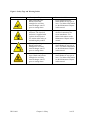


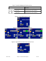

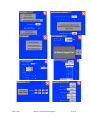
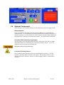


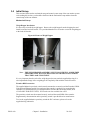
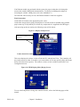

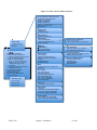
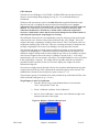
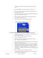


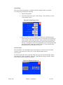
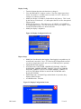


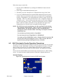

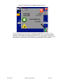


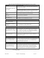


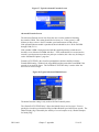
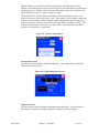
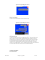
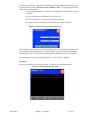


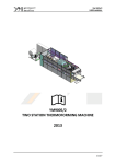


![sf-list [s]](http://vs1.manualzilla.com/store/data/005727021_1-5e70d84b679a2d9887789b982f459474-150x150.png)