1
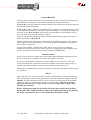
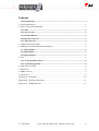
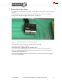
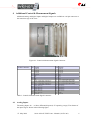
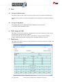
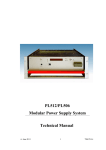
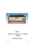
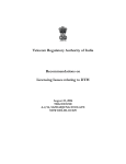
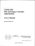
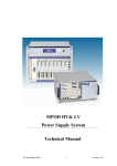
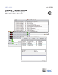
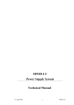
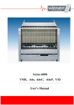
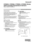
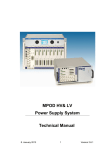
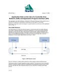
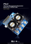
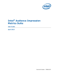
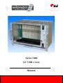
Series 3000 6U VME Crate Manual General Remarks The only purpose of this manual is a description of the product. It must not be interpreted as a declaration of conformity for this product including the product and software. W-Ie-Ne-R revises this product and manual without notice. Differences of the description in manual and product are possible. W-Ie-Ne-R excludes completely any liability for loss of profits, loss of business, loss of use or data, interrupt of business, or for indirect, special incidental, or consequential damages of any kind, even if W-Ie-Ne-R has been advises of the possibility of such damages arising from any defect or error in this manual or product. Any use of the product which may influence health of human beings requires the express written permission of W-Ie-Ne-R. Products mentioned in this manual are mentioned for identification purposes only. Product names appearing in this manual may or may not be registered trademarks or copyrights of their respective companies. No part of this product, including the product and the software may be reproduced, transmitted, transcribed, stored in a retrieval system, or translated into any language in any form by any means with the express written permission of W-Ie-Ne-R. Control Cabinet In the context of this user manual, the control cabinet must fulfill the requirements on fireprotective enclosures according to EN 60950 / IEC 60950 / UL 60950. All devices are intended for operation in control cabinets or in closed areas. The LAN connection and all wire connections between the different system parts must be done via shielded cable with conductive connector shells, which are fixed with screws. Furthermore, an additional fire-protective enclosure is required which must not affect proper air circulation. Safety After connecting the Crate to the mains, the mains input module is powered permanently. Filter and storage capacitors of the power factor correction module are charged with about 400VDC. The DC-On-Signal as well as a power switch at control board (if any installed) operates as a DC on/off switch only and not as a mains breaker. Therefore it becomes dangerous if the box cover is open. In this case a lot of components on high voltage potential get touchable! Before starting any kind of work inside the power box remove the unit from mains and wait a couple of minutes with your activities! Discharge the primary DC Filter-capacitors by use of a well isolated 22 ohm 10W resistor. 27. May 2009 Series 3000 6U VME Crate - Manual (*01785.A0) i Contents General Remarks...............................................................................................................i 1 General Information............................................................................................................1 2 CML 02 Front Panel Elements............................................................................................3 2.1 LEDs............................................................................................................................3 2.2 Power Switch...............................................................................................................3 2.3 Bus Reset Button........................................................................................................3 2.4 Ethernet Connector....................................................................................................4 2.5 USB Connector...........................................................................................................4 3 Temperature Sensor Inputs..................................................................................................5 4 Additional Control & Measurement Signals........................................................................6 4.1 Analog Inputs..............................................................................................................6 4.2 Digital Inputs..............................................................................................................7 4.3 Digital Outputs...........................................................................................................7 5 Fans.....................................................................................................................................8 5.1 Fan Speed Measurement............................................................................................8 5.2 Fan Speed Regulation.................................................................................................8 6 CML Setup via USB............................................................................................................8 7 Web Server..........................................................................................................................8 8 SNMP Control.....................................................................................................................9 9 OPC Server..........................................................................................................................9 Appendix A: Data Sheet.......................................................................................................10 Appendix B: Ordering Information......................................................................................11 Appendix C: SNMP OID Tree.............................................................................................11 27. May 2009 Series 3000 6U VME Crate - Manual (*01785.A0) ii Figures Figure 1.1: VME 3000 Block Diagram........................................................................2 Figure 3.1: Temperature Sensor Connection to CML02............................................5 Figure 4.1: Control & Measurement Signal Connector..............................................6 Figure 4.2: CML Analog Input Stage..........................................................................7 Tables Table 1: Ethernet Connector Pin Assignment............................................................4 Table 2: USB Connector Pin Assignment..................................................................4 Table 3: Control & Measurement Signal Connector...................................................6 27. May 2009 Series 3000 6U VME Crate - Manual (*01785.A0) iii 1 General Information Features ● 16 VME 64X slots 160mm with 80mm transition slots at the rear ● Voltage & Temperature measurement ● Ethernet connection IEEE 802.3 10BASE-T and IEEE 802.3u 100BASE-TX ● Fan tray removable, fully controlled ● Up to 2 CPIC power supplies (redundant operation, 500 W each) ● WWW-Server integrated, full control via SNMP protocol ● ON/OFF switch, VME/CPCI RESET button and 10 LEDs at the front panel ● 8 Digital inputs (2 optocouplers) ● 8 Digital outputs: (2 optocouplers) ● 4 Analog inputs ● PC-Control (connected to galvanic isolated USB) with free available software ● Switchable mains output (optional) ● Optional CAN-bus (galvanic isolated) ● ● Separate power supply for fan & control, independent from CPCI power Fully controlled, programmable trip thresholds (min./max. voltage, max. temperature) 27. May 2009 Series 3000 6U VME Crate - Manual (*01785.A0) 1 The W-IE-NE-R VME 3000 crates combine the advantages of standard Compact PCI power supplies with the features of our high-end VME 6000 systems. A VME 3000 crate is consisting of the 19”/7U bin with VME64x backplane, the control & measurement unit CML02, a removable fan tray and up to two 6U CPCI power supplies. Figure 1.1: VME 3000 Block Diagram The filtered mains is connected to an auxiliary power supply, which generates the necessary power to operate the CML02. If the system is switched on (with the front panel switch or via network) a power relay is closed and the CPCI power supplies are connected to the mains. The inrush current of CPCI power supplies can be quite high, so an optional inrush current limitation circuit is implemented. (This option is recommended if many VME 3000 crates are connected to a single fuse) After the VME voltages reach their correct values, VME SYSRESET is deactivated. From now on the voltages are compared with individual settable thresholds. If a failure is detected, the crate can switch off automatically. The fans inside the easy exchangeable fan tray are controlled and monitored by the CML, too. Because of the independent auxiliary power supply it is possible to cool down the crate after switching off the main supply, if required. Additional analog and digital input/output signals, which are provided by the CML02, are accessible at a 40 pin connector at the rear of the crate. 27. May 2009 Series 3000 6U VME Crate - Manual (*01785.A0) 2 2 CML 02 Front Panel Elements The V3000 crate is controlled by the CML02 (Control Measurement and Data Logging System) plugged into VME slot 17. 2.1 2.2 LEDs ● +3.3 V green LED, lighting if the 3.3 V system voltage is OK ● +5 V green LED, lighting if the 5 V system voltage is OK ● +12 V green LED, lighting if the +12 V system voltage is OK ● -12 V green LED, lighting if the -12 V system voltage is OK ● SYSRES red LED, lighting if the VME/CPCI bus reset signal is active ● SYSFAIL red LED, lighting if the VME SYSFAIL signal is active ● FAN 1 red LED, lighting if the left fan of the fan tray is defect ● FAN 2 red LED, lighting if the left fan of the fan tray is defect ● FAN 3 red LED, lighting if the right fan of the fan tray is defect ● STATUS green LED, lighting if the system is switched on Power Switch The power switch is used to switch the system power supply on (push the switch to the “ON” position) or off (push the switch to the “OFF” position. 2.3 Bus Reset Button If the bus reset button is pressed, the VME/CPCI RESET signal is activated for 200 ms. The button is sunk behind the front panel to prevent accidental activation. 27. May 2009 Series 3000 6U VME Crate - Manual (*01785.A0) 3 2.4 Ethernet Connector RJ45 Socket Pin Signal 1 2 3 4 5 6 7 8 Comment TX+ TXRX+ GND 1 GND 1 RXGND 2 GND 2 Table 1: Ethernet Connector Pin Assignment This is the standard NIC configuration. You need a 1:1-cable to connect a to a HUB, or a cross-over cable to connect to another NIC (e.g. a computer). There is no automatic signal crossing like with some routers. 2.5 USB Connector USB Socket Pin Signal 1 2 3 4 Comment VCC DD+ GND Table 2: USB Connector Pin Assignment This is the standard USB connector type B. The USB connection is galvanic isolated from the system to prevent ground loops. 27. May 2009 Series 3000 6U VME Crate - Manual (*01785.A0) 4 3 Temperature Sensor Inputs The CML02 has 8 temperature sensor inputs (semiconductor sensors with 1 kOhm resistance at 25°C). The System 3000 can be ordered with already installed sensors (option), for example one sensor at each CPCI power supply and one sensor at VME slot 1. Figure 3.1: Temperature Sensor Connection to CML02 The temperatures can be read with the SNMP network command (crate.sensor.sensorTemperature OID). Each temperature is compared with two threshold values (crate.sensor.sensorWarningThreshold and crate.sensor.sensorFailureThreshold OIDs). If the sensorWarningThreshold threshold of any connected sensor is reached, all fans will switched to their maximum speed. If the sensorFailureThreshold of any connected sensor is reached, the main power supply of the system is switched off. 27. May 2009 Series 3000 6U VME Crate - Manual (*01785.A0) 5 4 Additional Control & Measurement Signals Additional analog and digital inputs and digital outputs are available at a 40 pin connector at the transition cage of the crate. Figure 4.1: Control & Measurement Signal Connector 40 Pin Connector Pin Signal Pin Signal 1 3 5 7 9 11 13 15 17 19 21 23 25 27 29 31 33 35 37 39 2 4 6 8 10 12 14 16 18 20 22 24 26 28 30 32 34 36 38 40 reserved reserved reserved reserved reserved A1+ A1A3+ A3DO0+ (Optocoupler Transistor C) DO0- (Optocoupler Transistor E) DO1+ (Optocoupler Transistor C) DO1- (Optocoupler Transistor E) DO2 (TTL 5V) DO3 (TTL 5V) DO4 (TTL 5V) DO5 (TTL 5V) DO6 (TTL 5V) DO7 (TTL 5V) reserved reserved reserved reserved reserved A0+ A0A2+ A2DI0+ (Optocoupler LED anode) DI0- (Optocoupler LED cathode) DI1+ (Optocoupler LED anode) DI1- (Optocoupler LED cathode) DI2 (TTL) DI3 (TTL) DI4 (TTL) DI5 (TTL) DI6 (TTL) DI7 (TTL) GND reserved Table 3: Control & Measurement Signal Connector 4.1 Analog Inputs The analog inputs A0 ... A3 have differential inputs (0-3V operating range). The schema of the input stage is shown in the following figure. 27. May 2009 Series 3000 6U VME Crate - Manual (*01785.A0) 6 Figure 4.2: CML Analog Input Stage All resistors are low TK with 0.1% tolerance, so the input range can be changed by adding additional precision resistors without need for re-calibration. The external voltage range can be calculated with U XIN = R X 10 KΩ ⋅3V 10 KΩ The data can be accessed via SNMP (crate.signal.analogMeasurementVoltage OID). 4.2 Digital Inputs The digital inputs DI0 and DI1 are galvanic isolated with an optocoupler (SFH610). Both anode and cathode are accessible. To protect the device, a 120 ohm series resistor is implemented. The digital inputs DI2 ... DI7 are standard TTL inputs The inputs can be read by SNMP network commands (crate.signal.digitalInput OID) 4.3 Digital Outputs The digital outputs DO0 and DO1 are galvanic isolated with an optocoupler (SFH610). Both emitter and collector are accessible. The digital outputs DO2 ... DO7 are push/pull 5V CMOS TTL outputs The outputs can be set/reset by SNMP network commands (crate.signal.digitalOutput OID) 27. May 2009 Series 3000 6U VME Crate - Manual (*01785.A0) 7 5 5.1 Fans Fan Speed Measurement The rotation speed of each of the 3 fans inside of the fan tray is measured simultaneously. The fan rotation speed is accessible with SNMP network commands (crate.fantray.fanSpeed OID) 5.2 Fan Speed Regulation The nominal fan speed is changeable with the SNMP network commands (crate.fantray.fanNominalSpeed OID) 6 CML Setup via USB The CML02 is delivered completely configured for the system. If desired, the CML can be controlled with the MUSEcontrol software. The operation and usage of this software is described in a separate manual (CML01 – Control, Measurement & Data Logging System, document number *01773.A0). 7 Web Server The CML02 has a built-in web-server which allows the monitoring of the power supply with a standard web browser. 27. May 2009 Series 3000 6U VME Crate - Manual (*01785.A0) 8 Any write access to the web page (e.g. switch on/off) requires a user name and password. The user name is “private”, the default password is “private”, too. 8 SNMP Control The SNMP (Simple Network Management Protocol) is generally used to monitor and control computers and network routers. WIENER claimed a specific part of the SNMP namespace and implemented power supply specific items there. Protocol version 1 and 2c is implemented. The tree view of the implemented items is appended in 9 SNMP OID Tree. A detailed description of the SNMP functionality can be found in the corresponding MIB file (WIENER-CRATE-MIB.txt) If you are new to SNMP the www.Net-SNMP.org website is a good start. 9 OPC Server A server according to OPC Data Access V2.05 is optional available. OPC (OLE for Process Control) allows fast and secure access to data and information under Windows operating systems. As an industry-spanning, multi-vendor software interface, OPC minimizes connection and maintenance overheads. This server, running on a Computer with the Microsoft Windows XP operating system, enables access to all controllers which are connected to the network (TCP/IP). It is possible to ● ● ● ● access from any OPC Client application to the data of one or more servers encapsulating the properties specific to the server and type of communication commissioning support due to automatic scanning of the network and registration of communication stations restricting access rights by the underlying Microsoft DCOM. The details of the OPC server can be found in the manual delivered with the OPC server software. 27. May 2009 Series 3000 6U VME Crate - Manual (*01785.A0) 9 Appendix A: Data Sheet Analog Measurement Analog Input Range 0 ... 3 V unipolar Impedance 10 kOhm ± 0.1 % input to differential amplifier common mode range 0 ... 4 V accuracy 0.1 % resolution 12 bit typical, full scale Temperature Measurement Measurement Range -25 °C ... +125 °C accuracy ± 1 °C typical Communication Ethernet 10/100M BOOTP/DHCP or fixed IP address USB 2 isolated from system ground 27. May 2009 Series 3000 6U VME Crate - Manual (*01785.A0) 10 Appendix B: Ordering Information 0377.J177 VME 3000 BIN with the following options: • 3 temperature sensors at both CPCI power supply slots and VME slot 1 • Additional switched mains output connector at the rear • CPCI mains supply switchable via network • Additional front panels for unused slots • Fan speed programmable via network 0R00.0004 CML 02 VME 6U Control, Measurement and Data Logging System 0316.007C Fan Tray 0400.0000 Compact-PCI power supply 500W Appendix C: SNMP OID Tree Only a small part of general SNMP OIDs is implemented. This is the tree view: +--iso(1) | +--org(3) | +--dod(6) | +--internet(1) | +--directory(1) | +--mgmt(2) | | | +--mib-2(1) | | | +--system(1) | | | | | +-- -R-- String sysDescr(1) | | | Textual Convention: DisplayString | | | Size: 0..255 | | +-- -R-- ObjID sysObjectID(2) | | +-- -R-- TimeTicks sysUpTime(3) | | +-- -RW- String sysContact(4) | | | Textual Convention: DisplayString | | | Size: 0..255 | | +-- -RW- String sysName(5) | | | Textual Convention: DisplayString | | | Size: 0..255 | | +-- -RW- String sysLocation(6) | | | Textual Convention: DisplayString | | | Size: 0..255 | | +-- -R-- INTEGER sysServices(7) | | | Range: 0..127 This is the tree view of the W-IE-NE-R-specific SNMP namespace. It could be generated with the command „snmptranslate -w 80 -Tp WIENER-CRATE-MIB::wiener“. Because it's a general definition, usable for different types of crates, some items may be not implemented in the real hardware. Here the not relevant parts are omitted. The wiener OID is located at iso(1).org(3).dod(6).internet(1).private(4).enterprises(1). 27. May 2009 Series 3000 6U VME Crate - Manual (*01785.A0) 11 A detailed description of the SNMP functionality can be found in the corresponding MIB file (WIENER-CRATE-MIB.txt) +--crate(1) +--system(1) | +-- -RW- EnumVal sysMainSwitch(1) | | Values: off(0), on(1) | +-- -R-- BitString sysStatus(2) | | Values: mainOn(0), mainInhibit(1), localControlOnly(2), | | inputFailure(3), outputFailure(4), fantrayFailure(5), | | sensorFailure(6), vmeSysfail(7), | | plugAndPlayIncompatible(8) | +-- -RW- EnumVal sysVmeSysReset(3) | | Values: trigger(1) | +-- -RW- Integer32 sysDebugMemory8(1024) | | Range: 0..255 | +-- -RW- Integer32 sysDebugMemory16(1025) | | Range: 0..65535 | +-- -RW- Integer32 sysDebugMemory32(1026) | Range: -2147483648..2147483647 | +--input(2) +--output(3) | +-- -R-- Integer32 outputNumber(1) | | Range: 0..1999 | | | +--outputTable(2) | | | | | +--outputEntry(1) | | | Index: outputIndex | | | | | +-- ---- EnumVal outputIndex(1) | | | Values: u0(1), u1(2), u2(3), u3(4), u4(5), u5(6), u6(7), | | | u7(8) | | +-- -R-- String outputName(2) | | | Textual Convention: DisplayString | | | Size: 1..4 | | +-- -RW- Integer32 outputGroup(3) | | | Range: 0..1999 | | +-- -R-- BitString outputStatus(4) | | | Values: outputOn(0), outputInhibit(1), | | | outputFailureMinSenseVoltage(2), | | | outputFailureMaxSenseVoltage(3), | | | outputFailureMaxTerminalVoltage(4), | | | outputFailureMaxCurrent(5), | | | outputFailureMaxTemperature(6), | | | outputFailureMaxPower(7), | | | outputFailureTimeout(9), | | | outputCurrentLimited(10), outputRampUp(11), | | | outputRampDown(12) | | +-- -R-- Opaque outputMeasurementSenseVoltage(5) | | | Textual Convention: Float | | | Size: 7 | | +-- -R-- Opaque outputMeasurementTerminalVoltage(6) | | | Textual Convention: Float | | | Size: 7 | | +-- -R-- Opaque outputMeasurementCurrent(7) | | | Textual Convention: Float | | | Size: 7 | | +-- -R-- EnumVal outputMeasurementTemperature(8) | | | Values: ok(-128), failure(127) | | +-- -RW- EnumVal outputSwitch(9) | | | Values: off(0), on(1) | | +-- -RW- Opaque outputVoltage(10) | | | Textual Convention: Float | | | Size: 7 | | +-- -RW- Integer32 outputAdjustVoltage(11) | | | Range: -128..127 27. May 2009 Series 3000 6U VME Crate - Manual (*01785.A0) 12 | | +-- -RW- Opaque outputCurrent(12) | | | Textual Convention: Float | | | Size: 7 | | +-- -RW- Opaque outputVoltageRiseRate(13) | | | Textual Convention: Float | | | Size: 7 | | +-- -RW- Opaque outputVoltageFallRate(14) | | | Textual Convention: Float | | | Size: 7 | | +-- -RW- Integer32 outputSupervisionBehavior(15) | | | Range: 0..65535 | | +-- -RW- Opaque outputSupervisionMinSenseVoltage(16) | | | Textual Convention: Float | | | Size: 7 | | +-- -RW- Opaque outputSupervisionMaxSenseVoltage(17) | | | Textual Convention: Float | | | Size: 7 | | +-- -RW- Opaque outputSupervisionMaxTerminalVoltage(18) | | | Textual Convention: Float | | | Size: 7 | | +-- -RW- Opaque outputSupervisionMaxCurrent(19) | | | Textual Convention: Float | | | Size: 7 | | +-- -RW- Opaque outputConfigMaxSenseVoltage(21) | | | Textual Convention: Float | | | Size: 7 | | +-- -RW- Opaque outputConfigMaxTerminalVoltage(22) | | | Textual Convention: Float | | | Size: 7 | | +-- -RW- Opaque outputConfigMaxCurrent(23) | | | Textual Convention: Float | | | Size: 7 | | +-- -RW- Opaque outputSupervisionMaxPower(24) | | Textual Convention: Float | | Size: 7 | | | +-- -R-- Integer32 groupsNumber(3) | | Range: 1..1999 | | | +--groupsTable(4) | | | +--groupsEntry(1) | | Index: groupsIndex | | | +-- ---- Integer32 groupsIndex(1) | | Range: 0..1999 | +-- -RW- EnumVal groupsSwitch(9) | Values: undefined(-1), off(0), on(1) | +--sensor(4) | +-- -R-- Integer32 sensorNumber(1) | | Range: 0..8 | | | +--sensorTable(2) | | | +--sensorEntry(1) | | Index: sensorIndex | | | +-- ---- EnumVal sensorIndex(1) | | Values: temp1(1), temp2(2), temp3(3), temp4(4), temp5(5), | | temp6(6), temp7(7), temp8(8) | +-- -R-- Integer32 sensorTemperature(2) | | Range: -128..127 | +-- -RW- Integer32 sensorWarningThreshold(3) | | Range: 0..127 | +-- -RW- Integer32 sensorFailureThreshold(4) | Range: 0..127 | +--communication(5) | +--snmp(1) | | | | | +--snmpCommunityTable(1) | | | | | | | +--snmpCommunityEntry(1) | | | | Index: snmpAccessRight | | | | 27. May 2009 Series 3000 6U VME Crate - Manual (*01785.A0) 13 | | | +-- ---- EnumVal snmpAccessRight(1) | | | | Values: public(1), private(2), admin(3), guru(4) | | | +-- -RW- String snmpCommunityName(2) | | | Size: 0..14 | | | | | +-- -RW- Integer32 snmpPort(2) | | | +--can(2) | +-- -RW- Integer32 canBitRate(1) | +-- -R-- String canReceive(2) | | Size: 14 | +-- -RW- String canTransmit(3) | Size: 14 | +--powersupply(6) | +-- -R-- String psSerialNumber(2) | | Textual Convention: DisplayString | | Size: 0..255 | +-- -R-- Integer32 psOperatingTime(3) | +-- -RW- String psDirectAccess(1024) | Size: 1..14 | +--fantray(7) | +-- -RW- String fanSerialNumber(2) | | Textual Convention: DisplayString | | Size: 0..14 | +-- -R-- Integer32 fanOperatingTime(3) | +-- -R-- Integer32 fanAirTemperature(4) | +-- -RW- Integer32 fanSwitchOffDelay(5) | | Range: 0..900 | +-- -RW- Integer32 fanNominalSpeed(6) | | Range: 0..3600 | +-- -RW- Integer32 fanNumberOfFans(7) | | Range: 0..12 | | | +--fanSpeedTable(8) | | | +--fanSpeedEntry(1) | | Index: fanNumber | | | +-- ---- Integer32 fanNumber(1) | | Range: 1..12 | +-- -R-- Integer32 fanSpeed(2) | +--rack(8) +--signal(9) +-- -R-- Integer32 numberOfAnalogInputs(1) | Range: 0..8 | +--analogInputTable(2) | | | +--analogInputEntry(1) | | Index: analogInputIndex | | | +-- ---- Integer32 analogInputIndex(1) | | Range: 1..8 | +-- -R-- Opaque analogMeasurementVoltage(2) | Textual Convention: Float | Size: 7 | +-- -R-- BitString digitalInput(5) Values: d0(0), d1(1), d2(2), d3(3) 27. May 2009 Series 3000 6U VME Crate - Manual (*01785.A0) 14