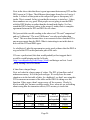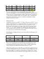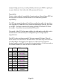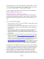
1
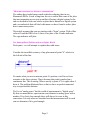
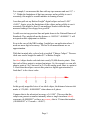
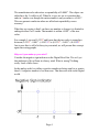
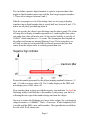
Jitter Bug - Watch your Shumatech DRO display dance
By Lawrence W. Gill and R. G. Sparber
Version 5
July 15, 2007
Copyleft protects this article.
Conclusion
With a careful choice of filter values, you can eliminate almost all of your
caliper jitter and not degrade your Shumatech DRO’s accuracy.
Overview
This article discusses the basics of trying to use digital means to measure
movement. Jitter is a natural result. Means are suggested to minimize this
side effect and their consequences discussed. A design choice that we
consider a minor software bug is explained and a work-around offered. The
impact of this bug on system accuracy and repeatability is presented.
Various sets of data are offered which were derived from using the quieted
Shumatech DRO.
Table of Contents
CONCLUSION .............................................................................................................................................. 1
OVERVIEW ................................................................................................................................................. 1
TABLE OF CONTENTS ................................................................................................................................. 1
"WHAT WE HAVE HERE IS A FAILURE TO COMMUNICATE" .......................................................................... 2
OUR ANALOG WORLD COLLIDES WITH OUR DIGITAL WORLD .................................................................. 2
WHY CAN'T YOU MAKE UP YOUR MIND?..................................................................................................... 4
THE THREE BEARS STORY ......................................................................................................................... 9
The Filter Value Section Procedure .................................................................................................. 10
THE 5 TENTHS INDICATOR FLICKER......................................................................................................... 10
THE ROUND OFF ERROR BUG ................................................................................................................... 13
ACCURACY VERSUS REPEATABILITY ....................................................................................................... 16
REAL DATA.............................................................................................................................................. 22
Setting Expectations........................................................................................................................... 22
Overview of the Data ......................................................................................................................... 23
A close up View.................................................................................................................................. 23
A View Over a Larger Range............................................................................................................. 24
Absolute Accuracy ............................................................................................................................. 25
Repeatability...................................................................................................................................... 26
MATCHING THE PROCEDURE TO THE DESIRED ACCURACY ...................................................................... 27
Page 1
"What we have here is a failure to communicate"
We authors have traded many emails related to reducing jitter in our
Shumatech DROs. It took a long time for use to realize that some of the jitter
that was tormenting us was just an artifact of having a digital system. In the
end we decided to write one article on jitter that is natural to a digital system
and a second article that will deal with means we have found to reduce jitter
due to unnecessary noise.
This article assumes that you are starting with a "clean" system. With a filter
value of 0 and the DRO set to 0, there is no jitter of the 5 tenths indicator.
The sign indicator will jitter.
Our Analog World Collides with our Digital World
Don't panic - we will attempt to explain these odd terms.
Consider the incredible accuracy of my placement of point "A" relative to
the left end of the line.
No matter what you use to measure point A's position, it will never be as
accurate as the above picture. That is because this point is marked on a
continuous line. This is analog. Where exactly is point A? It is right where I
drew it. The problem illustrated here is that we have no perfect numerical
way to represent this distance.
We live in "analog space" but the world of measurement is "digital space".
By this we mean that we represent an exact distance in analog space with a
number. If we look close enough, there will always be error in this
conversion. It is only when we consider how the measurement will be used
can we determine if it is good enough.
Page 2
For example, I can measure this line with my tape measure and read 1½" ±
1
/8". Within the limitations of that tape measure and my ability to use it
accurately, this might be a usable number in framing a house.
I can then pull out my Harbor Freight® digital caliper and read 1.490"
±0.001". Again, given the limitations of the caliper and my ability to use it
accurately, this might be fine if I am making a bracket while the tape
measure reading is too sloppy for a good fit.
I could even trot my precious line and point down to the National Bureau of
Standards. They might tell me the distance is 1.489369" ±0.000001". I will
not question their equipment or abilities.
Even in the case of the NBS reading, I might have an application where I
need one more digit of accuracy. The fact is all measurements are an
approximation.
With that in mind, take a closer look at an ideal "Chinese Caliper". The nonideal ones can be bought for under $17 at Harbor Freight.
An ideal caliper breaks each inch into exactly 20,480 discrete points. Note
that each of these points is assigned an integer. So, for example, we can talk
about a point at 2 or 3 but never at 2.4. In the analog work, there is a point at
2.4 but when the caliper converts this point to a digital approximation, it
finds that 2 is the closest value.
In this greatly magnified view of our ideal caliper, the distance between tick
marks is 1/20,480 = 0.00004883" when shown to 8 places.
Compare that to the advertised accuracy of ± 0.001". This says that the
caliper can generate a number internally where a single increment ideally
represents ±0.00004883" yet have an accuracy that is 23 times that number
(±0.00004883" x 23 counts = ±0.001").
Page 3
The manufacturer also advertises a repeatability of 0.0005". The caliper can
either have the 5 visible or off. When lit, it says we are at a position that
ends in 5 tenths even though the entire number is only accurate to ±0.001".
This can generate confusion when we talk about repeatability versus
accuracy.
What they are saying is that I can have any number as long as it is limited to
ending in either 0 or 5 tenths. That number is within ±0.001" of the true
value.
For example, I can read 0.1235" and know that the true value is someplace
between (0.1235" - 0.001" =) 0.01225" to (0.1235" + 0.001"=) 0.01245".
Just in case this is still a bit fuzzy in your mind, we will present this concept
again later using graphs.
Why can't you make up your mind?
Consider the negative sign indicator on the Digital Read Out. We set 0 yet
that indicator is like a flame in a heavy wind. What is wrong? Nothing
really. Look a little closer.
In the analog world, we define a positive number as being equal to or greater
than 0. A negative number is less than zero. That does not work in the digital
world.
Page 4
We can define a positive digital number as equal to or greater than 0 but
negative digital numbers must start with the first integer negative number, 1. There are no integers between 0 and -1.
What do you propose we do if the analog value we are trying to display
translates into a digital number that is exactly half way between 0 and -1? It
makes me all jittery just thinking about it.
Now lets overlay the caliper's specifications onto the above graph. The claim
of being able to display a number repeatable to 5 tenths implies that a jitter
just under that value will not be seen. So the implied stability is just shy of
±0.0005" which translates to ± 11 counts. This assumption does depend on
the caliper not having any internal filtering. Even if I am wrong here, we
will later see that we can use the DRO to directly measure the jitter that
comes from the caliper and it is certainly greater than zero.
Picture the number generated by the caliper jumping randomly between -11
and +11 with an average value of 0. The 5 tenths display on the DRO will
not change given a filter value of 0.
Now consider what is going on with the negative sign indicator. It should be
flickering wildly if tied directly to this number. It may annoy you, but it is
reflecting the true sign of the number being sent from the caliper.
One way to reduce the flickering is to buy a better caliper. Say you bought a
caliper accurate to ± 0.000005". That's ± 5 microns. If held completely still,
it would send the DRO a nice stable number. The sign indicator would then
be rock solid. Well, almost true.
Page 5
A physical motion of ±0.00005" (±50 microns) will produce a change in
caliper output of ±1 count to the DRO. This magnitude of vibration turns out
to be rather common. You just got your jitter back in the negative sign
indicator.
Now consider the overall system. You took a scale accurate to ±0.000005"
and put it into a DRO able to display to the nearest ±0.0005". This
effectively degrades the scale to an accuracy of ±0.00025". Ouch!
A more economical way to reduce flicker is to increase the DRO's filter
value. Given a caliper putting out a jitter of ±11, we can stop it with a filter
value of 12. You may recognize this number since it is the default.
If you feed the filter software with a range of counts from -11 to +11 and an
average value of 0, it will send a nice stable 0 to the DRO's display and the
negative sign indicator will not flicker. Lets look closer at how this works.
Say we have the filter value set to 12. Our caliper jitter is ± 11.
We zero the DRO's display. The value sent to the DRO by the caliper can be
Page 6
any value between -11 counts and +11 counts and is randomly moving
between these two values. A count of -11 represents a displacement of 0.0005" and a value of +11 represents a displacement of +0.0005" as shown
by the red vertical bar centered at 0,0. The filter software sees this ±11 jitter
and calculates an average of 0, which it sends to the DRO's display.
The caliper is then moved exactly 0.002" as shown by the blue arrow. The
filter watches the count change and looks for a family of values that are
within ±11 of the final number. When the caliper stops at 0.002", the filter
software has seen the count that corresponds to 0.0015", 0.002", and 0.0025"
float by. It therefore arrives at the correct answer of 0.002" and blocks the
±11 count jitter.
There is an implied assumption in using the filter. It is assumed that the jitter
from the caliper is centered on the correct value. That is a reasonable
assumption if analog forces cause the jitter. These forces have an equal
probability of raising the count as lowering it so are symmetric around the
true count. If the jitter has a component that is not symmetric, the filter will
pass that through as truth.
So filtering is good, right? If more is better, then too much is just right. Well,
like all good things, more is not always better. Look what happens if we set
the filter value at 12 but have no jitter.
Page 7
We zero the DRO's display. The caliper is then moved exactly 0.002" as
shown by the red arrow. The filter software watches the count change and
looks for a family of values that are within ±12 of the final number. When
the caliper stops at 0.002", the software has seen the count that corresponds
to 0.001", 0.0015", and 0.002". It therefore arrives at the incorrect answer of
0.0015".
Next consider what happens if the caliper approaches 0.002" from a higher
value.
Page 8
We start at 0.004" and move the caliper down the bar until it reads 0.002" as
shown by the blue arrow. When the caliper stops at 0.002", the software has
seen counts that correspond to 0.003", 0.0025", and 0.002". It therefore
arrives at the incorrect answer of 0.0025".
So if we have the filter value set to block jitters corresponding to ±0.0005"
but you have no jitter, we actually get a new error equal to the filter value.
The Three Bears Story
OK, now lets step way back and see what is going on here.
If the filter value is too small, the display will either have just the negative
sign indicator jittering or may also have the 5 tenths indicator jitter. If things
are very noisy, the first thou digit may even jitter. The negative sign
indicator jitter may be annoying but is really harmless. Jitter in the 5 tenths
indicator or thou digit causes ambiguity and therefore error.
Page 9
If the filter value is much larger than the jitter, we will get additional error
due to the filter action.
But if the filter value is matched (just right) to the jitter, we will get no jitter
and also have the best possible accuracy.
So the take home message is to match your filter value on each axis to the
jitter on that axis.
The Filter Value Section Procedure
This is the best procedure we have found to measure jitter and determine the
correct filter value. We use the HEX display mode here because it is more
sensitive to jitter than the decimal mode. You don't need to read the HEX,
just note if it is stable.
1.
2.
3.
4.
switch to HEX display mode (hit FCN and then INCH/MM)
set each scale to slow mode (FCN and scale select)
set all axes to 0
Watch each scale and record the maximum and minimum values. If you
see FFFFFF, move the axis until you read only numbers that start with 0.
5. Subtract the minimum value from the maximum value and add 1; this is
your filter value for this axis*. See the User's guide for how to input these
values.
6. When done, hit FCN and then INCH/MM to return the display to
decimal inches.
The 5 Tenths Indicator Flicker
Now lets consider flickering of the 5 tenths indicator. We are going to again
run head-on into the problems of a digital world of measurements.
*
If you see a max value that contains letters, you filter value is greater than 9. You may be able to reduce
this jitter by making a simple hardware change. See my article "Shumatech DRO Scale Power Noise
Injection".
Page 10
As I smoothly slide the caliper along, I will get numbers that approximate
my position. If I land at 0, then I expect the 5 tenths indicator to bc off . If I
land at 0.0005", I expect to see that indicator light up. But what do you want
me to do at 0.00025"? The standard answer is to minimize round off error,
so I place the transitions as shown above. When I sit at 0.00025", the
magnitude of the error will be 0.00025" regardless of whether the 0.0005"
indicator is on or off.
Now put the jitter back into the picture.
Page 11
With the DRO display set to 0 and a filter value of 0, the caliper can jitter by
±11 counts or just shy of ± 0.00025" and not bother the 5 tenths indicator.
We know that the jitter can't be greater than ± 11 counts or it would show.
Consider what it means to have a jitter of ± 11 counts. We are on the hairy
edge of causing the 5 tenths indicator to flicker. Any noise introduced into
the caliper that bumps that jitter by even one count will cause flickering. We
call this a zero noise margin situation. Even the smallest amount of noise
injected into the position sensor of the caliper can cause jitter in the 5 tenths
indicator.
Now look what happens when the caliper is moved slightly.
I have put the center of the jitter at 0.00025". The 5 tenths indicator is going
to jitter just as much as the negative sign indicator did at 0.
We can again look at our options. If we buy a near perfect caliper, tiny
physical motion will most likely cause jitter of the number sent to the DRO.
If we happen to land at one of these transition points, we will get jitter. We
have also wasted a lot of accuracy.
Alternately, we can set our filter values on each axis to match the jitter of its
caliper. This will minimize the jitter around these transition points.
Page 12
With each filter value set correctly, the negative sign indicator and the 5
tenths indicator should now both be as stable as possible.
The Round off Error Bug
One person's "bug" is another person's design decision. In an email from
Scott Shumate, the creative force behind the Shumatech DRO, I learned a
critical fact: He chose to do truncation rather than rounding. He also clearly
stated this fact in the User's manual on page 9 and in message #6532 in the
Shumatech archives.
Rounding off to the nearest 0 or 5 tenths would have taken 5% of the total
memory. Rightly so, that memory was spent instead on great features.
Technically we don't have a bug here, but I would not call it a feature either.
It does cause the DRO's display to not be as accurate as the caliper is by
itself and that gives us a twinge of pain.
Scott went with truncation, which uses much less memory. The result is that
numbers that end in a value less than 5 tenths have the tenths place set to 0.
Numbers that end in a value greater than or equal to 5 tenths but less x0
tenths have the tenths place set to 5. You can clearly see this in the data
shown on page 24.
Note that truncated numbers are always rounded towards 0.
This means we get a built-in average error with truncation that makes
displayed numbers smaller than they are internal to the DRO.
Ah, but we got ahead of ourselves. Let's step back a bit.
With our jitter under control we can now clearly see small changes in the
DRO’s display as we move the caliper. By using a push rod type of Dial
Test Indicator along side the DRO, it is possible to compare their readings.
Much to our surprise, they sometimes agreed very well but at other times the
DRO read low. The DRO never read high. Here is a non-symmetric error,
which is not often found in the analog world. We are looking at the effects
of truncation.
First lets consider what happens as counts are processed into decimal inches
when rounding is used. The caliper generates a Hexadecimal (HEX) number,
Page 13
which is sent to the DRO. The software takes this number and filters out the
jitter. It then adds an offset so we can set zero at any point. The result is a
HEX value that can be seen by hitting FCN and then INCH/MM. A single
increment in the HEX display represents a single count from the caliper so
ideally 0.00005". The final step for the software is to convert this HEX
number to decimal inches where the smallest indicator is 5 tenths.
On the graph shown below, it looks like the HEX numbers are analog and
the decimal numbers jump in large steps. The blue line is the ideal
conversion case if the decimal display had the same resolution as the HEX
display.
Rather than inflict HEX on you, we have used a pocket calculator to convert
the HEX into decimal. You can see that as the converted value moves to a
x.xxx25" or x.xxx75" point, the 5 tenths indicator changes state. We saw this
in detail as we looked at 5 tenths indicator jitter. Well, that is not exactly
what we get.
Page 14
Here you see the effects of truncating. Note, for example, that when the
converted HEX moves from 0 to 0.25 thou, we do not jump from 0 to 0.5
thou. Instead it happens when we reach 0.5 thou. Similarly, when we reach
0.75 thou, we should change the decimal display from 0.5 thou to 1 thou.
This does not happen until the converted HEX gets to 1 thou.
After all of our work to get the 5 tenths indicator to be stable, we now find
that this indicator can have an error of up to 50% due to truncation.
Maybe the best way to appreciate this error is to look at the system’s overall
performance. You may very likely decide that this bug is no big deal.
Page 15
Accuracy versus Repeatability
Our calipers have an advertised accuracy of ±0.001". The following graph
reflects this fact.
Say we set the display to 0 and then move the caliper exactly 0.001". We can
expect the DRO to display one of the following numbers: 0.0000", 0.0005",
0.0010", 0.0015", or 0.0020". This range of values represents all possible
decimal numbers within ±0.001" of the true value of 0.001".
If we move back to 0 and then back to 0.001" again, the display should read
the same number as seen the first time. That is because the repeatability is
0.0005". We get a consistent reading each time but it may still be off by as
much as ±0.001".
Stop for a moment and think about the
repeatability and accuracy of a finger type
Dial Test Indicator. Its value comes from
being able to consistently tell you when the
finger is in the same position relative to the
indicator's body. This is an extremely useful
Page 16
thing to know in machining. The finger DTI has excellent repeatability, but
its accuracy is limited. For more details, see
http://rick.sparber.org/Articles/DTI/DTI.htm.
Before we overlay the effects of truncation look again at its effect with an
ideal caliper.
Lets try out a few numbers to get our minds around this thing. Starting at 0,
move towards 0.0005" on the "thou moved" axis. The display will show
0.0000" until we hit 0.0005". Then it will jump to 0.0005". Now return to 0
and start moving towards -0.0005". The display will read 0.000" until we
reach -0.0005" and then jump to -0.0005". Can you see that numbers other
than zero will read smaller by 0.0005" unless you are right at a transition
point?
Now we will overlay the caliper's error limits of ±0.001" and see how
truncation effects it.
Page 17
The key thing to remember is that truncation causes numbers to always be
rounded towards 0. Looking at a few specific cases may help us understand
this rather complex graph.
Page 18
Consider the case of moving just shy of 0.001". I have shown the purple line
a bit off from 0.001" in order to make it easier to see which side of each
transition it is on.
Ideally, moving just shy of 0.001" should cause the display to show 0.001".
When we crank in just caliper error, we should expect the display to have a
number bounded by 0.001" ± 0.001". We find that 0.0000", 0.0005",
0.0010", 0.0015" and 0.0020" fall within these limits. Don't forget that we
would see just one of these numbers. Due to truncation, we loose that top
value of 0.0020". Our error limits actually improved when compared to just
the tolerance of the caliper. The caliper alone gave ±0.001" but the caliper
plus truncation gave the smaller range of +0.0005" -0.001". Can you see that
for displayed numbers between 0 and -0.001" that the error limits are
+0.001" -0.0005"?
Sure looks like truncation improves accuracy. Well it does if we don't move
more than 0.001" from a zero set point. What happens if we move beyond
this charmed range?
Page 19
Consider moving just shy of 0.0015".
Again I have positioned the purple line relatively far from 0.0015" so it is
clear which side of the transitions we are on.
We moved to just shy of 0.0015" and should expect to see 0.0000", 0.0005",
0.0010", 0.0015", or 0.0020". Note that the error limit this time is -0.0015" +
0.0005". The positive error limit benefited from truncation but the lower
error limit took a hit. While the caliper alone had a lower error limit of 0.001", adding the DRO increased the error limit to 0.0015".
Page 20
What is going on here? Look at it this way:
Truncation that reduces the gap between maximum and minimum is going to
help us. Those areas are show shaded in green. Truncation that increases the
gap is going to hurt us and is in red.
So it turns out that if we moves less than ± 0.001", truncation improves
accuracy. Outside of this range, it can cause numbers to be smaller by
0.0005".
If we happen to already be receiving a measurement from the caliper that is
at the bottom limit of permissible error (0.001 below ideal), truncation will
cause us to see a number on the display that is 0.0015" below ideal except as
noted above. Check the data on page 24 and you will see 2 cases where this
is true. If I can hit this condition twice out of 6 measurements, it can't be that
rare. Of course, you never know when you will hit truncation so must
assume that the DRO adds to the error limit by between 0 and -0.0005".
Have we tried to make a mountain out of a mole hill? Perhaps so, but this
widening of the error limit is due to a design choice as opposed to the real
Page 21
error caused by our non-ideal caliper. We really like the full feature set so
are not saying that it was a bad choice, only a painful one for us. We hope
that the upgraded Shumatech DRO will include a round off routine rather
than just doing truncation.
Real Data
Setting Expectations
Before we present any data, I want to set expectations correctly. People that
read this data will be coming from two very different "worlds".
In one world we have people making parts to absolute dimensions. They
make these parts which are combined with somebody else's parts. The parts
better fit. This can only happen reliably if all parties use measurement
instruments traceable back to organizations like the National Institute of
Standards and Technology.
Consider the accuracy necessary if two different companies make blocks
with a hole in the middle. With the outside of the blocks aligned, it will be
really hard to get the holes to be aligned to within 0.0001".
In the other world, dominated by hobbyists, are one-off parts that must fit to
other parts made by the same person. If this person has a mic that is off by
say 5%, then the first part will be 5% off. They then make the second part
using the same mic so it is 5% off too. The parts fit together just fine. High
accuracy really don't matter in this world. Reproducibility does matter.
Again consider the case of having two blocks with matching holes. As a
hobbyist, I would just line up the edges and drill a single hole through both
blocks at the same time. I could even bore it out. The resulting holes will be
almost perfectly aligned.
So if you are from the world of traceable accuracy, just skip to the third set
of data. The rest will only make you mad.
Page 22
Overview of the Data
The following three sets of data have varying degrees of rigger associated
with them. The first set compares the DRO to my recently rebuilt finger DTI
over a range of 0 to 3 thou. The second set uses an ENCO push rod DTI of
unknown accuracy. All I do know is that it has not been abused. The third
set uses 1-2-3 blocks good to ±0.0001".
In all cases, we are only showing a tiny snap shot of the total caliper's
accuracy. It is possible that by shifting the caliper just a few thou, the errors
might be different.
A close up View
Here is a comparison run using my recently factory rebuilt Starrett finger
type Dial Test Indicator as a reference. The finger was set so the force to
move it was perpendicular to it. This minimizes the error due to angular
displacement. For more on how to use one of these DTIs, see
http://rick.sparber.org/Articles/DTI/DTI.htm.
DTI (thou)
HEX
from
DRO
HEX converted
(thou)
DTI-Hex
converted
(thou)
Set 0
Set 0
0
0
-1.0
FEC
-1.0
0
-2.0
FD6
-2.1
-0.1
-3.0
FC3
-3.0
0
0.0
1
+0.05
-0.05
1.0
14
1.0
0
2.0
28
2.0
0
3.0
36
2.6
+0.4
4.0
50
3.9
+0.1
Retest: 3.0
38
2.7
+0.3
Page 23
Note in the above data that there is great agreement between my DTI and the
DRO except at 3.0 thou. The difference then jumps from close to 0 up to 4
tenths. A recheck of that point on the caliper still gave a discrepancy of 3
tenths. This is normal. In fact, given that the accuracy is stated as ± 1 thou,
these numbers are very good. Most people are not going to run the DRO
with the HEX display on rather than the decimal inch display. So if we
round the HEX converted values to the nearest 5 tenths, there is complete
agreement between the DTI and DRO for all values.
Did you catch the careful wording in the above text? We said "comparison"
and not "calibration". The word "difference" was also used rather than
"error". This was done because there is no reason to believe that the DTI is
any more accurate than the DRO. What is interesting to me in this data is
how well the DTI and DRO agree.
As a hobbyist, I take this agreement as pretty good evidence that the DRO is
as good as the DTI on this particular part of the scale.
If I were a professional, this data would probably at best suggest that it
would be worth bringing out the Jo blocks
(http://en.wikipedia.org/wiki/Gauge_block) and doing a real test. I can't
justify owning a set of Jo blocks.
A View Over a Larger Range
Next we looked at a larger range of values. The DTI is from Enco and of
unknown accuracy. It is of the push rod type. We really have the same
situation as in the last table of data. As a hobbyist I say that I was using this
DTI to measure movement of the table and the DRO is taking over this
function. If they agree, then I am no worse off for accuracy. Clearly Jo
blocks would give far more credible results. Now, when we are just talking
about seeing how the truncation effects, DTI accuracy is irrelevant.
DTI (inches) HEX from HEX converted
DRO
to decimal
Set 0
0.100
0.200
0
7F5
FE9
0
0.0995
0.1989
Page 24
HEX
Decimal
converted displayed on
and rounded
DRO
0
0
0.0995
0.0990
0.1990
0.1985
0.300
0.400
0.500
0.600
17F5
1FF1
27F7
2FE9
0.2995
0.3993
0.4996
0.5989
0.2995
0.3990
0.5000
0.5990
0.2990
0.3990
0.4995
0.5985
Do you see that in all cases the simulated DRO display value, "HEX
converted and rounded", is closer to the DTI than the DRO displayed value?
In two cases the “Decimal displayed on DRO” value showed a deviation of
1.5 thou while the simulated values were all within 1 thou. I consider this a
demonstration that the tiny error due to truncation can degrade readings
enough to put you out of spec.
Absolute Accuracy
And finally, we used a set of SPI 1-2-3 blocks. The box says 98-423-7. I was
unable to find information on exactly this number but it appears to be part of
a family with an accuracy of ±0.0001". The test was run at 80° F. The
blocks were bolted together to form an L shape with the horizontal surface
being 1", 2", or 3" wide. My finger DTI attached to the quill was used to
sense touchdown first on the left vertical face and then on the right vertical
face. The Z-axis was locked before each reading.
All of the above readings used my Z-axis caliper while the following use the
X-axis caliper.
Block dimension
±0.0001"
1.000"
2.000"
3.000"
DRO decimal
DRO HEX
HEX converted
1.0000"
2.0000"
2.9995"
5009
A007
EFFD
1.0005"
2.0004"
3.0000"
These blocks represent the most accurate dimensions in my shop. In all 3
measurements the HEX converted value is within ± 0.0005" of the block's
value. Certainly well within the advertised accuracy of ± 0.001".
If this software bug is just a “mole hill” to you, then life is good and you can
go back to making chips. If you are unwilling to accept the added error, then
one work around is to switch to hex when you get to within 0.002” of your
final value and do your own conversion. On the other hand, if you are really
Page 25
trying for high precision, you will probably not trust your DRO to guide you
on your finish cut. Lets look at the full spectrum of choices.
Repeatability
Next is a short study of repeatability. I again used my Starrett finger DTI but
an Optovisor was used to set the needle to 0 with the best possible
repeatability.
The DTI was secured to the quill and the assembly lowered to the top of my
vise. Both the DTI and DRO were zeroed at touchdown. Then the DRO was
set to HEX. Each pass consisted of starting with the DTI about 0.2" above
the surface. It was then lowered until the DTI read 0.
The needle of the DTI is the same width as the tick marks on the dial so it is
not that hard to tell when they are in alignment given enough optical
magnification.
The HEX value was then recorded. This was repeated 10 times. Then all
HEX values were converted to decimal inches. The table only shows the last
two HEX digits. The higher order digits were either all Fs for negative
decimal numbers and all 0s for positive decimal numbers. Color was used on
the decimal numbers to make it easier to count the zeros.
Pass
0
1
2
3
4
5
6
7
8
9
10
HEX HEX converted
value
to decimal
Set 0
0
FF
-0.00005"
FF
-0.00005"
FF
-0.00005"
FF
-0.00005"
FF
-0.00005"
02
+0.00010"
FF
-0.00005"
01
+0.00005"
02
+0.00010"
00
0.00000"
Page 26
This data says that I was able to hit touchdown repeatedly within +0.00010"
-0.00005". With a better magnifying glass, it might be possible to get down
to ±0.00005" which would be ± 1 count of the HEX display.
I want to remind you that the above data addresses observed repeatability
which has nothing to do with accuracy.
Matching the Procedure to the Desired Accuracy
It is good to decide how much accuracy you want before starting any job.
The Home Shop Machinist may not feel a “time is money” pressure, but we
all know that our time on this earth is finite. More accuracy will cost you
time.
Let’s review our accuracy options.
1. For an accuracy of ± 0.0015”, just use the DRO. You must still be careful
to accurately set your zero points.
2. For an accuracy of ± 0.001”, use the DRO until you get within 0.0015” of
your final position. Then switch to HEX and do your own conversion to
decimal inch.
3. For an accuracy of ±0.0005”, you must rely on at least your mic as you
go for your final position. You will then need to either use a DTI in
setting the depth of cut or may find that the DRO in HEX display mode is
good enough.
4. For an accuracy of better than ±0.0005”, you may wish to use a sine bar
and DTI as described at http://rick.sparber.org/Articles/sb/sb.htm. This
procedure seems to be good to ±0.0004” but often is good to better than
±0.0001”. The article deals with thickness at a point and does not address
the fact that practical machining is all about cutting surfaces. See
http://rick.sparber.org/Articles/PM/pm.pdf for the rest of the story. Using
these techniques I was able to cut a test cube using my RF30 to within
±0.0004” with a surface variation of ±0.0002” across all 3 dimensions.
The difference in time and effort is dramatic across these 4 options. Option 1
is essentially zero time. Option 2 may take you 15 seconds per reading if you
are using a programmable calculator to do the HEX to decimal conversion.
Option 3 might take 30 seconds to take the reading with the mic. Then it
may take a minute to set up the DTI or maybe 15 seconds to read and
convert the HEX display. Option 4 can take 3 minutes to set the desired
value. When you are going for the highest precision, much time is first spent
Page 27
being sure your machine and set up are true and solid so that 3 minutes may
be a small part of the total effort.
We welcome your comments and corrections. Please send them to
[email protected].
Even the two of us are not as smart as all of us.
Larry Gill
[email protected]
Rick Sparber
[email protected]
Web site: http://rick.sparber.org
Page 28