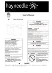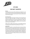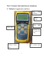
1
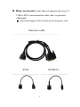
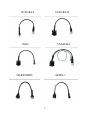
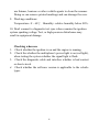
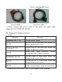
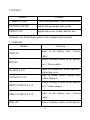
Part 1 Scanner Introduction & Attentions Multiplexer appearance and keys Diag. cable interface Display screen Pwr Signal Light light 燈 direction keys up down left right Perform(enter) ESC(return)key key key 1 Diag. accessories: total 10pcs of adaptors plus 1pcs of USB to R232 communication cable (have to purchase additional) ※ Stand-alone upgrade shall add other brands diagnostic cable Main test cable SYM KYMCO 2 SUZUKI-I SUZUKI-II PGO YAMAHA HARTFORD AEON-1 3 Power cable USB to R232 cable(OPT) Buttons descriptions ▲▼ Up down Arrow Keys:choose test items ◄ ►Left right arrow keys:choose test items,form feed YES Enter, perform NO ESC,Return 4 Attentions 1. 2. 3. 4. 5. 6. 7. 8. Use restrictions The displays screen and illustrations (such as key markings) in this manual are for illustrative purpose only, and may differ somewhat from the actual items they represent. The contents of this manual are subject to change without notice. In no event shall Shenzhen Zeus Technology Co., LTD be liable to anyone for special, collateral, incidental, or consequential damages in connection with or arising out of the purchase or use of these materials. Shall Shenzhen Zeus Technology Co., LTD not be liable for any claim of any kind whatsoever against the use of these materials by any other party. Avoid use and storage in areas subjected to temperature extremes. Very low temperatures can cause slow display response, total failure of the display. Also avoid leaving the scanner in direct sunlight, near anywhere else it might be exposed to very high temperatures. Heat can cause discoloration or deformation of the scanner's case, and damage to internal circuitry. Never attempt to disassemble the scanner or tamper with the connection settings without permission. Never press the keys of the scanner with a ballpoint pen or other pointed object. Use a soft, dry cloth to clean the exterior of the scanner. If the scanner becomes very dirty, wipe it off with a cloth moistened in a weak solution of water and a mild neutral household detergent. Wring out all excess moisture before wiping the scanner. Never 5 use thinner, benzene or other volatile agents to clean the scanner. Doing so can remove printed markings and can damage the case. 9. Working conditions: Temperature:0~60℃;Humidity: relative humidity below 80%. 10. Don't connect to diagnostic test sync when examine the ignition system sparking voltage Test, or high-pressure disturbance may result in equipment damage. Checking when use 1. Check whether the ignition is on and the engine is running. 2. Check the whether the multiplexer's power light is on (red light), when testing the system whether the signal light is flash. 3. Check the diagnostic cable and interface whether is bad contact or short-circuit. 4. Check whether the software version is applicable to the vehicle types 6 Part 2 Connection Specifications 1、Scanner accessories and adaptors positions Testing accessories Multiplexer 7 Main test cable 3pin diagnostic adaptor Connection methods: connect the main test cable 8 connect the diagnostic cable Connect to the car diagnostic cable 9 Power connect cable head Power cable main test cable ※Please connect the power cable to the main test cable when diagnosis new YAMAHA models. Diagnostic adaptor positions: 1. SYM Models Dayanhan RS21 150 R1 125 Hanjiang FI 125 RV180 FIGHTER 125/150 RX110 RV250 Position In the FRONT TRUNK On the top of Fuel-tank cap, inside the Philip's head screw cover On the top of Fuel-tank cap, inside the Philip's head screw cover Inside the right rearview mirror dredge-up with a small coverage On the center of front trunk, inside the Philip's head screw cover On the top left of front trunk, inside the Philip's head screw cover Under seating washer, inside the battery box ※Models not listed please refer to the original repair manual 10 2. KYMCO Models Position Common Scooter Under seating washer, inside the battery box XCITING 250/500 below the passenger right pedal VENOX 250 Right side cover, bellow battery box ※Models not listed please refer to the original repair manual 3. YAMAHA Models VINO 50 Position Pedal, in the battery box ( Green cable) Below Seating washer, in the battery RSZ100 MAJESTY 125 CYGNUS X 125 NEW CYGNUS X 125 NEW CYGNUS X 125 box(Green cable) Inside left handlebar, on the smal lift protecting cover Next to trunk, inside battery box (white adaptor) Below Seating washer, in the battery box(white adaptor) Pedal, in the battery box ( Green cable) GTR 125 Below Seating washer, in the battery 11 box (white adaptor) Pedal, in the battery box ( Green BWS 125 cable) ※Models not listed please refer to the original repair manual 4. PGO Models Common Scooter Position Under seating washer, inside the battery box ※Models not listed please refer to the original repair manual 5. SUZUKI Models Position X-STAR 125 Under seating washer, inside the battery box ADDRESS 125 Pedal, in the battery box(white adaptor) Part 3 Operation Descriptions (Take SYM RV250 as sample) 1. Connection Connect 25pin connector to connection socket,(connect DB9 side to 3pin adaptor’s DB9, another side is power cable don’t need to be connected.) 2. Perform function options 12 Start the scanner and enter, it will come out options as below 1.Diagnostic procedure 2.Updating software 3.Language selection 4.System info Perform : 1.Diagnostic procedure : Enter maintenance diagnostic procedure. Perform:2. Updating software:have to connect the main test cableto computer’s COM PORT, then connect to the power, and do software upgrade.(pls contact the service department for detailed update information). Perform:3. Language selection: at present support Traditional Chinese and Vietnamese switch. Perform:4. System info:can read out scanner’s S/N no. etc. information. 3.Diagnostic procedure ● Use ▲、▼ keys to select 1.Diagnostics, press YES to 13 enter, it will come out Models selection as below SYM KYMCO YAMAHA SUZUKI PGO Up▲Down▼;Previous◄Next► ● Select SYM with▲、▼keys, press YES to enter SYM main function list. Page 1 System info Numerical Analysis Freeze Data analysis Read trouble code Clear trouble code Up▲Down▼;Previous◄Next► Page 2 Idle speed CO adjustment Up▲Down▼;Previous◄Next► 14 System info Enter this option will display system ecu information, as below is RV250 detailed ECU information. Page 1 Scanner I D:00020000 00020 Software version:002 Diagnosis version No.: 03 Model: SYM LAA071211 Up▲Down▼;Previous◄Next► Page 2 003 Name: RV250 HMC Up▲Down▼;Previous◄Next► Numerical Analysis 15 System Info Numerical Analysis Freeze Data analysis Read trouble code Clear trouble code Up▲Down▼;Previous◄Next► Select Numerical Analysis to enter Numerical Analysis Engine RPM 0 Trouble code No. 9 Battery Voltage 12.0 Petrol Pump Status OFF Intake Mainfold Pressure 128 RPM V KPa Up▲Down▼;Previous◄Next► Engine RPM Throttle Position Throttle Position Engine Temperature 02 Voltage 0 0 0.00 N/A 4990 RPM % V ℃ Mv Up▲Down▼;Previous◄Next► 16 Engine RPM 0 02 Heater OFF Engine Water Temperature 72 Atmospheric Pressure 101.0 Intake Air Temperature 51 Up▲Down▼;Previous◄Next► Engine RPM Secondary Air Injection Time Ignition Angle Step Motor 0 RPM ON 0.0 ms -1 ° STABLE Up▲Down▼;Previous◄Next► Engine RPM Crankshaft Test Terminals Idling target ISC Steps 0 CW OPEN 1800 115 RPM RPM Up▲Down▼;Previous◄Next► 17 RPM ℃ kPa ℃ Engine RPM Learned Steps 0 0 RPM Up▲Down▼;Previous◄Next► Numerical analysis is the numeric figures of the working status for motor engine,through this analysis we can know whether motor works normally. For the convenience of users, by this scanner you can compare the current working value with standard value to confirm whether it's normal, for example: Engine RPM Throttle Position Throttle Position Engine Temperature 02 Voltage 0 0 0.00 N/A 4990 RPM % V ℃ mV Up▲Down▼;Previous◄Next► Select Throttle Posistion, click YES to enter option as below: Standard Value and Description Waveform Up▲Down▼;Previous◄Next► 18 Select Standard Value and Description will display: Standard Value:Idle speed withn 1.5% Description: Sensor is 3PIN, Middle Y/B line is 5V, the white coffee line under the Voltage input Previous◄ ;Next►<NO>Return is Signal Output(Full closed=0.56V Wide open=3.69V Upper G/R line is GND a) Working Voltage value=5.0V ±0.1V b) Previous◄ ;Next►<NO>Reture Throttle full-closed(throttle not rotated) →Volt value=0.6±0.2V.C) Throttle (rotate the throttle to wide-open)→ Volt value=3.77V ±0.1V) Previous◄ ;Next►<NO>Return According to the stardard value description, and compare with the current data to analyse whether the motor works normally. Select Waveform option, it will display current wave to help analysis. 19 Freeze Data Analysis In the function list select Freeze Data Analysis will display(The data shows here is the relevant data when the motor comes fault): Function List System Info Nunercial Analysis Freeze Data Analysis Read touble code Clear touble code Up▲Down▼;Previous◄Next► Freeze Data Analysis option (Page 1) Engien RPM Trouble code No. Trouble code Engine water Temperature Engine Temperature 0 RPM 9 P0351 5.0 V N/A Up▲Down▼;Previous◄Next► Freeze Data Analysis option (Page 2) 20 Engien RPM Throttle Position Throttle Position Engien Temperature 02 Voltage 0 0.0 5.00 5.0 4990 RPM % V V mV Up▲Down▼;Previous◄Next► Freeze Data Analysis option (Page 3) Engien RPM Battery Voltage 0 12.3 RPM V Up▲Down▼;Previous◄Next► Read trouble code In the function list select Read trouble code displays: Function List System Info Nunercial Analysis Freeze Data Analysis Read trouble code Clear trouble code Up▲Down▼;Previous◄Next► Read trouble code option 21 Current trouble code Freeze trouble code ALL Up▲Down▼;Previous◄Next► Select current trouble code to enter display trouble code, select the trouble code by up/down keys P0351 P0230 P0135 P0120 P0105 Up▲Down▼;Previous◄Next► Select the trouble code, press YES and enter trouble code description display Ignition circuit malfunction Action steps: 1. make sure if ignition circuit resistance conformce to specification? (3±0.3Ω,20℃) 2. Make sure connector or cable Up▲Down▼;Previous◄Next► 22 if circuit-open? ECU PIN18 &B/Y line 3. Make sure ignition coil power supply if normal(12~ 15V)?R/Y line(12V Power Relay) 4. follow the new component replacement Up▲Down▼;Previous◄Next► flow to make sure if ignition coil fault Up▲Down▼;Previous◄Next► Operation of reading freeze trouble code and all the trouble is the same as reading current trouble code, Some motors have options for past trouble code or history trouble code, the reading operation is the same too. Clear Trouble code Function list 23 System Info Numercial analysis Freeze Data Analysis Read trouble code Clear trouble code Up▲Down▼;Previous◄Next► In the function list select Clear trouble code will display: Swift Ignition ON, Engine stop running YES Perform Note! Before clear trouble code pls stop engine running and swift ignition ON. Press YES, clear trouble code successfully display Clear trouble code completed ﹤YES﹥Return 24 Idle speed CO adjustment Return to the Page 2 of main function list then select Idle speed CO adjustment. Main function list Idel sppeed CO adjustment Up▲Down▼;Previous◄Next► Idel speed Co adjustment options CO adjustment value: CO value reading: ▲:plus 0.5 or 1 ►:Plus 2.5 or 5 -64.0 -64.0 ▼:Minus 0.5 or 1 ◄:Minus 2.5 or 5 ﹤NO﹥Return 其他選項 General motors's enter main menu includes the above, because the different models, some motors may have different menu. ◆ Reset/Reset Instruction(SYM R1-125) The last selection is the “Reset/Reset Instruction” After entered into 25 Main menu of Model R1-125: Reset/Reset Instruction Up▲Down▼;Previous ◄Next► Select Reset/Reset selection: Reset Throttle Position Reset ABV Time Adjustment COFPC Reset Up▲Down▼;Previous ◄Next► 88 Press YES to reset throttle position, the presentation would be displayed: No engine on YES Perform Up▲Down▼;Previous ◄Next► 26 Press YES: Please switch key-off and then switch-on YES→ Up▲Down▼;Previous ◄Next► According to the presentation, switch off the Key and then switch on, select Yes,it will display as below: The action has been finished, enter into numerical value Analyse and confirm if the ACCEL ON value is 100%, if the ACCEL OFF value is 100% YES Return Up▲Down▼;Previous ◄Next► Select Reset ABV time adjustment, it will display: Reset Throttle Position Reset ABV Time Adjustment COFPC Reset Up▲Down▼;Previous ◄Next► 27 Setting has been finished YES Return The Operation of COFPC Reset and ABV reset are the same: ACCEL Reset has been finished,ABV Reset has been finished,please restart the engine of Vehicle YES Return Reset has been finished。 YAMAHA Operation guide: (Take BWS125 as sample) Function list Select the Simple Model from the function list: 28 Simple model Diagnostic Model Special Adjustment Up▲Down▼;Previous ◄Next► Press YES,then it displays:(Please switch off the Key according to the presentation) Please switch off the Key YES—〉 Press YES, it will show: Waiting the Key-on… If no connection Within 15 seconds, please try to make key-on again 29 when the connection is successful, the page will go to: Engine Speed Engine Temp. Trouble code 0 RPM 20 ℃ 28 Up▲Down▼;Previous ◄Next► Select the desired observation Fault code from the recurrent list, then press YES Enginee Speed Engine Temp. Fault code 0 RPM 20 ℃ 28 Up▲Down▼;Previous ◄Next► Display results 28. Engine Temp.Sensor becomes abnormal 〈NO〉Return Select the Simple model from the function list: 30 Simple Model Diagnostic Model Special Adjustment Up▲Down▼;Previous ◄Next► Press YES:(Pls Switch Key off according to the instruction) Please Switch key off YES—〉 Press YES: Pleas wait key-on… If no connection Within 15 seconds, please try to make key-on again (No Engine on) When the connection is esablished,it will go to: 31 DO1 Throttle Angle 0.0 ° ◄►Function Shift 〈NO〉Return DO3 Intake-Air Pressure 0.0 kPa ◄►Function Shift 〈NO〉Return DO5 Intake-Air Pressure 20 ℃ ◄►Function Shift 〈NO〉Return 32 DO7 Vehicle Speed Ripple 0 ◄►Function Shift 〈NO〉Return DO7 Vehicle Speed Ripple 0 ◄►Function Shift 〈NO〉Return DO9 Battery Monitoring Voltage 14 V ◄►Function Shift 〈NO〉Return 33 D30、D36、D52、D54 action test, press YES D30 Ignition coil 0 〈 YES 〉 Fuel Injector action times ON / OFF ◄►Function Shift 〈NO〉Return Review the stored trouble code: D61 Inspect record trouble code ◄►Function Shift 〈NO〉Return Press YES to clear the trouble code D62 Clear trouble code 12 〈YES〉Clear the trouble code ◄►Function Shift 〈NO〉Return 34 12 5 PART 4 Appendix Install USB to R232 communication cable (Have to purchase additional) driver 1、 Double click the driver Icon as photo When there is Devic dirverinstall/uninstall dialog box,click INSTALL 2、 If there is warning like photo as below, select continue install 35 3、 Clike OK after installation finishing 36 4、 Connect the USB to R232 cable to computer with the USB port, then it will automatically come out Welcome to search for new hardware wizard screen, when asking whether connect to windows update to search for software, select NO, not this time, click Next to continue. Select Install the software automoatically, click Next to continue 37 5、 Completing the Found New Hardware Wizard, click Finish. 38 6、 Confirm USB to R232 cable driver has been well installed. Right click My Computer, select Properties, When come out System Properties, select Hardware, Click Device Manager 39 In the Device Manager screen click +Ports (COM & LTP), if there is COM items in the drop-down menu, it's said the driver installation is ok, like the screen shows as below, 40