1
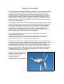
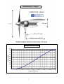
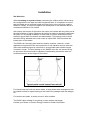
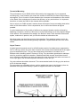
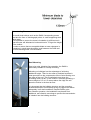
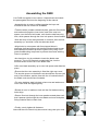
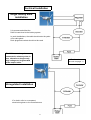
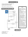
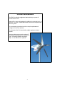
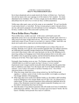
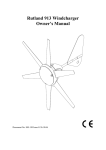
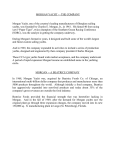
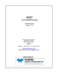
USER’S MANUAL
tle Here
D400
Wind
Generator
Serial Number:_______________
Voltage:_____________________
Safety Issues
• When installing the D400, exercise due care at all times. The turbine weighs 15
kilograms and is awkward in shape. It is best to plan the installation carefully in
advance and enlist some help when erecting the machine in order to avoid accidents.
• Complete as much of the installation procedure as possible at ground level.
• Choose a calm, dry day for your installation if possible.
• D400 blades are quite sharp, particularly on their trailing edges. Handle with care.
• D400 is robustly engineered, but contains high-energy ferrite magnets that can be damaged if the machine is dropped or handled heavily.
• When running, particularly if disconnected from the batteries, D400 is capable of
producing high voltages. Caution must be exercised at all times to avoid electric shocks.
• Always observe correct polarity when connecting D400 to an electrical circuit. Reverse
polarity connection will result in damage to the wind generator.
• The D400 must be appropriately fused at all times.
• Never approach the path of the blades when the machine is operating as severe
personal injury could result.
• Always stop the machine and secure the blades before
attempting maintenance.
• Ensure that all batteries are disconnected when undertaking maintenance.
PLEASE NOTE:
The D400 is designed to be permanently connected to a
suitable electrical load such as a battery bank, dump
regulator or inverter.
It should never be allowed to run unloaded,
ie. open-circuit, for more than a few minutes.
In an open-circuit condition, the D400 will overspeed, and
very high voltages can be produced.
There is also a risk of damage to the machine’s rectifiers.
1
Contents
Safety issues
1
Introduction
2
Features of the D400
3
Dimensions
4
Output
4
Checklist (parts, tools etc)
5
Principles of wind energy
5
Installation - Boats
6
Terrestrial mounting
7
Guyed towers
7
Freestanding towers
8
Roof mounting
8
Assembling the D400
9/10
Electrical connections
11
Regulation
11
Stopping the D400 / Braking switch
12
Electrical installation/ Circuit diagrams
13/14
Performance and expectation
15
Routine maintenance
16
CE Conformity
17
Guarantee
17
Thank you for purchasing the D400 Wind Generator,
designed and manufactured by Eclectic Energy Limited.
The D400 is one of the most efficient, powerful and well-engineered
turbines currently available. It is important, however, that you
thoroughly read the entire manual prior to installation to ensure
optimum safety and performance of the equipment.
Should you be left with any questions or uncertainties, having read
the manual, please contact your authorised dealer or Eclectic
Energy Ltd direct for further clarification.
2
Features of the D400
The D400 has been developed specifically to operate in close proximity to people.
The noise and vibration usually associated with small wind turbines has been
designed out of the D400. This has been achieved by making the turbine run
relatively slowly for a given electrical output. In a given wind speed and a given
electrical output, the D400 rotates at less than one quarter the speed of some
competitor units. Combined with its rugged engineering and advanced computerdesigned air blades, this makes the D400 the most reliable and benign turbine of
its class currently available.
The air blades are precision injection-moulded from glass reinforced nylon and as
well as featuring taper and twist incorporate a special low-Reynolds airfoil section
which varies continually in camber from tip to root. Because of the production
method used, the blades are extremely consistent in terms of mass and can be
replaced singly should damage occur without losing turbine balance. The
alternator and yaw shafts are precision-ground from 316 grade stainless steel,
and the D400’s body is a robust aluminium alloy casting.
The bearings are high quality and generously sized, and are protected by
twin-lipped radial shaft seals.
The tail is formed from aluminium sheet into a shallow ‘S’ section in order to
impart stiffness and prevent resonance. All aluminium parts are etched,
alachromed and finished in a tough polyester powder coat.
The D400 utilises a 12-pole, 3-phase axial field alternator of very high efficiency. It
comprises two large annular magnet rotors with stator coils positioned in between.
The stator coils themselves are wound from heavy gauge copper and are
encapsulated in a heat-inductive resin. This in turn is bolted to a machined shelf
within the aluminium housing, so ensuring excellent heat dissipation from the
machine. A combination of the advanced air blade and alternator design delivers
unparalleled efficiency in low wind speeds together with the ability to produce
sustained high outputs in high winds.
Eclectic Energy Ltd’s attention to
design and quality should ensure
your D400 gives years of
trouble-free service.
Congratulations on your purchase.
3
Dimensions, output
D400 Wind Generator Output
500
450
400
Power in watts
350
300
250
200
150
100
50
0
0
5
10
15
20
Wind speed in knots
4
25
30
35
40
Checklist
Check that you have received in your
delivery two cartons containing:
1 x alternator body
5 x air blades
1 x tail
2 x hub plates
1 x tower sleeve
1 x air hub spacer
Fasteners
Required for installation:
The principles of Wind Energy
Wind is a function of solar energy unevenly heating the
Earth’s surface. As warmer air rises at the equator, cooler
air flows in to replace it, setting in train global convective
currents. This circulation which we call wind distributes
both heat and moisture more evenly around the earth so
providing us with a comfortable planet to inhabit.
The same process of convection also happens more
locally, for example differential heating producing the
summer land and sea breezes. These streams of moving
air also provide us with an inexhaustible, if intermittent,
energy source.
A wind generator works by converting some of the kinetic
energy in wind stream to electricity. Air weighs about
1.2 kg per cubic metre at sea level, and kinetic energy is
expressed by mass times the square of its velocity.
Understanding this is a key to appreciating the energy
available to wind generators.
In short, the amount of energy available to the wind
generator rises dramatically with increasing wind speed.
Regrettably, the reverse is also true. In low wind speeds
there is very little energy to capture.
It is important, therefore, when considering the site of your
wind turbine, that you choose a site with the highest
possible wind speeds. In addition, the airflow should be as
free from turbulence as possible.
5
Mounting Tower
Extension cable
Batteries
Battery terminals
Connection blocks
Cable clips
Etc
Additional system items:
Regulator
Charge splitters
Volt and ammeters
Tools:
Spanners
Screwdriver
Wire strippers
Etc
Installation
Site Selection
When mounting on a yacht or boat, positioning the turbine will be influenced by
the configuration of the boat and other equipment fitted. It is important to ensure
that the blades are at sufficient height such that injury to the crew from rotating
blades is unlikely. A minimum height of the lowest point of the airblades above a
crewed area should be 2.4 metres.
Also ensure that no part of the turbine can come into contact with any other part of
the boat’s fittings or rigging. Because the turbine is subject to dynamic loads when
the yacht is in a seaway in addition to wind loads, the tower should be securely
braced or guyed both fore and aft and athwartships. The bracing struts or wires
should be firmly attached to the main tower at a point 200 –300 mm below the
lowest point of the blades.
The D400 is an inherently quiet and low vibration machine. However, certain
applications may benefit from the introduction of anti-vibration mounts under the
main tower and bracing struts. Note that no unsupported tower should exceed
2 metres in length. The wind loading on the D400’s rotor disc can exceed 50 kg,
so any tower structure should be capable of withstanding at least this load in a
horizontal direction at the height of the turbine.
For inland watercraft such as narrow boats, a hinge-down tower arrangement can
be utilised to allow for rapid lowering of the turbine for passage under low bridges
etc.
For ketches and yawls, a mizzen mount is often suitable.
The D400 is also suitable for mounting on stern arches and targas.
Contact your Dealer or Eclectic Energy Limited for further information.
6
Terrestrial Mounting
The performance of your D400 will be influenced by the topography of your proposed
mounting site. In any location, the nearer the surface of the Earth, the lower the prevailing
wind speed. This is a result of friction between the air stream and obstacles on the surface
of the Earth. Such turbulence will reduce the efficiency of any wind turbine. It is important,
therefore, to locate the D400 in the clearest airflow possible.
Aim to mount your D400 at least 8 metres above the height of any surrounding obstruction
within a 100 metre radius. If this is impractical, aim to mount the turbine as high as
possible.
A useful assessment of the quality of airflow at a proposed location can be achieved by
attaching a streamer, similar to a kite’s tail, to a pole and letting it fly at the proposed height
of the turbine. If the streamer flies straight, the airflow is clear. If the streamer flutters and
spirals, turbulence is present, and you should consider an alternative site.
Mounting towers can be either guyed or free-standing. Free-standing towers need to be
very substantial and are therefore generally expensive. Guyed towers are the more usual
choice.
Guyed Towers
A typical guyed terrestrial mount for a D400 would consist of a tubular tower supported by
four or more guy wires. No more than 2 metres of the tower should extend above the upper
guy wire attachment point. The guy wires themselves should be of at least 4 mm in
diameter with a breaking strain in excess of 50 kg. They should be galvanised or stainless
steel for protection against the weather. Shackles and bottle screws should be at least 5
mm in diameter and where guy lines are looped, the loop should be held with a minimum of
3 wire rope grips, and should incorporate a thimble to form the eye.
Guy wire radiuses should be observed. The recommended radius for the guy wire anchors
is 0.6 of the tower height.
Four guy wires are preferable to three, as this enables the tower to be hinged up from its
base with three guy wires already in place to support the tower as it ascends.
7
Freestanding Towers
For small wind turbines such as the D400, free-standing towers
can take the form of old telegraph poles, or a self-supporting steel
latice tower.
It is important to ensure the tower’s foundation is sufficient such
that the tower will withstand a horizontal load of 70 kg at the height
of the turbine.
In order to ensure that an acceptable blade to tower clearance is
maintained, a stub tower should be used between the D400 and
the free-standing tower. See illustration.
Roof Mounting
Due to its quiet, vibration-free operation, the D400 is
particularly suitable for rooftop mounting.
Mounting on buildings has the advantage of achieving
additional height. There is also often a localised increase in
wind speed due to the compression effect of wind flowing over
the ridge of the roof. This is particularly true when the
prevailing wind is at 90 º to the roofline. Generally speaking, a
mount height of 1.5 to 2.5 metres above the ridge line will
place the turbine in the best air flow.
It is important that the building structure and the mounting
bracket attachment is sufficiently strong to support the turbine
adequately in all wind conditions. Despite D400’s quiet,
low vibration operation, the installation may benefit from
additional, anti-vibration mountings to prevent the transmission
of vibration into the building structure.
8
Assembling the D400
Your D400 is supplied in two cartons. Unpack these and check
the parts against the list at the beginning of this manual.
•Assemble the air rotor by sliding together the keys and
mortises at the hub of the five air blades.
•Take the white, powder-coated hub plate, pass two 5mm bolts
and washers through the inner holes, and fit the rotor hub
spacer over the 5mm bolt heads, such that the shaft securing
hole, which passes through the rotor hub spacer, faces forward.
•With the body of the wind generator on its back, offer the hub
assembly up, and slide it onto the alternator shaft.
•Align holes in rotor spacer with 6mm tapped holes in
alternator shaft and secure with two 6mm button head screws
and shakeproof washers provided.Tighten firmly using a nut
grade threadlocking compound to prevent the screws working
loose in operation.
•An aluminium ring is provided to locate the blade roots
securely. The ring is inserted, rounded side first, into the
annular recess on the rear of the blade roots.
Offer rotor blade assembly up to rotor hub spacer and slide into
place.
•Ensure that the rotor assembly is fitted the right way round.
The annular groove on the blade roots should face the rear (tail
end) of the machine, and the face with the 10 conical holes in
the blade roots should face forewards.
•Fit outer stainless steel hub plate, place nuts and washers on
inner 5mm bolts and tighten gently.
•Rotate air rotor in relation to hub until the five blade securing
holes align.
•Pass a 5mm bolt through the inner powder-coated plate such
that it passes right through the rotor blade and outer hub plate,
fitting a washer and nut each time.
•Finally, evenly tighten all fasteners.
Note that the rotor should only be secured using new nyloc nuts.
9
Assembling the D400 (continued)
• Place the turbine face down on its rotor, and attach the tail
using the three M6 nuts and bolts provided. Note that the tail
should be fitted to the left-hand face of the casting flange
when the D400 is viewed from the rear. The large stainless
steel washers should also be fitted on the left-hand side.
• To fit the rotor spinner, offer up the axial splits in the
moulding to the leading edges of the blades while holding the
spinner square and central over the hub. Gently open each of
the axial splits, and encourage it to pass over the leading
edge of the blades.
• Finally, rotate the spinner anti-clockwise such that it
effectively screws onto the blade roots. Snap the rear edge of
the blades slot behind the trailing edge of the five blades (see
pictures).
• Remove the tower spacer from the D400’s yaw shaft, and
check it for fit with the proposed mounting tower. It is far
preferable to discover it does not fit at this juncture rather than
when you are actually attempting installation. The standard
tower liner has an outside diameter of 41 mm and is designed
to slide into standard aluminium or steel scaffolding tubing
with a nominal outside diameter of 48mm and inside diameter
of 41.5mm.
Should the tower liner not fit the tower tube correctly, consider sourcing an alternative
mount tower or contact your supplier to order an alternative tower liner.
On no account attempt an installation where the tower liner is a ‘sloppy’ fit in the tower,
as this will lead to instability when the machine is operating, and could lead to
machine damage.
• The tower liner is retained to the yaw
shaft by three grub screws. Once the
machine has been installed, the tower
liner should be secured by drilling two
holes through the top of the tower into the
tower liner to a depth of 12mm with a
4mm drill, finally securing with
two 8 x12mm self-tapping screws.
Your D400 is now ready for installation
10
Electrical Connections
Connecting cables between D400 and the battery bank or inverter should be appropriately
sized to minimise transmission losses. For low voltage machines transmission losses are
always a consideration, so it is advisable to keep cable runs as short as possible and be
prepared to use heavier gauge cable for longer runs.
Typically, you should use cable of at least 4.5 square mm conductor cross section (AWG
11). For longer runs approaching 30 metres you should consider 17 square mm cable
(AWG 5) for the 12 volt D400.
Note that the transmission losses associated with the 24 volt machine are lower, and 6
square mm (AWG 10) would suffice for a 30 metre run.
Where D400 is fitted to a tall mounting tower, ensure the weight of the hanging cable is
taken by a strain relieve arrangement within the tower, rather than simply hanging on the
D400 cable connection.
Fusing:
D400 is capable of producing very high currents. A line fuse must always be installed
in order to protect the D400.
A blade-type 50 amp rated fuse and holder is supplied with 12 volt machines.
A blade-type 30 amp rated fuse and holder is supplied with 24 volt machines.
Note: where a braking switch is fitted, the fuse should be installed between the switch and
the turbine.
Regulation
Where D400 is being used for battery charging we strongly recommend that a regulator
is installed as part of the system. The regulator’s function is to prevent battery damage
through overcharging. The regulator works by sensing battery terminal voltage and as a
pre-set upper limit is approached, the regulator progressively dumps output from D400
to a pair of large, foil-wound resistors, where the surplus energy is lost as heat.
The regulator unit supplied by the manufacturer incorporates a charge splitter so its
output can be connected to two independent battery banks simultaneously. It will
preferentially charge the lower of the two banks first. The unit will also accept the output
from up to 100 watts of solar panel.
The regulator should be installed within 1 metre of the battery bank and the dump
resistors mounted horizontally in an area where air is free to pass over them for cooling.
See wiring diagrams on pages 13 and 14.
11
Stopping the D400
The D400 is a robust machine and can safely be left operating in most windspeeds.
However, where extremestorm force winds are forecast, it is prudent to stop the machine
and secure the rotor blades with a rope lashing.
The D400 can be stopped by gripping the tail and turning the machine out of the wind,
securing the blades once they have stopped rotating.
Braking Switch:
A braking switch can be fitted which provides a convenient aid to stopping the D400.
The switch should be a double throw ‘break before make’ type, rated at least at
40 amps. When operated, the switch disconnects the batteries from the D400
before short-circuiting the turbine.
The short circuit slows the rotor blades making it easier to turn the machine out of the wind
and to secure the blades.
Please note: the D400 utilises a purpose-designed, highly efficient,axial field ironless
alternator. This configuration delivers exceptional power outputs coupled with smooth, low
friction running. These attributes are retained to some extent when the braking switch is
applied, and in consequence the braking effect is not as marked as with other
machines of more conventional alternator design.
In certain conditions, the rotor can overcome the braking effect altogether, which
produces damagingly high currents in the stator windings.
For this reason the braking switch should only be used to slow the unit prior to
manually stopping it. It is not a parking switch. If the machine is left to run with the
braking switch engaged, serious damage can occur to the generator.
PLEASE NOTE
The braking switch should only
be used to slow the unit prior to
manually stopping it.
If the machine is left to run with
the braking switch engaged,
serious damage can occur.
12
Electrical Installation
Single battery bank
installation
It is recommended that the
D400 is hard wired to the battery system.
In yacht installations, the cable should enter the yacht
via a cable gland.
Deck plugs and sockets should not be used.
The D400 must always be
connected to a battery when in
use, otherwise a dangerously
high voltage can be generated
at the output cable.
*For fuse sizes,
see note on page 11.
Unregulated installation
If in doubt, refer to a competent
electrical engineer or the manufacturers.
13
Electrical Installation
Connect the output cable to the battery bank(s) using
the suggested wiring diagrams for guidance.
Remember to observe the correct polarity.
RED to POSITIVE + and BLACK to NEGATIVE –
Where a battery monitor
is fitted
Twin Battery Bank Installation
If your system is fitted with a
digital battery monitor, a shunt
will have been installed close to
the batteries.
One side of the shunt is
connected directly to the battery
terminal or busbar.
All other connections are made
to the opposite side of the
shunt.
The shunt is most usually
connected in the negative line.
When wiring the D400 to a
system fitted with a shunt,
observe polarity and connect the
appropriate D400 output
cable to the non-battery side of
the shunt.
Again observing polarity, the
other D400 output cable should
be made directly to the battery
terminal or busbar.
The D400’s output will now pass
through the shunt and the
monitor will display a reading.
If the shunt is bypassed by
connecting both positive and
negative output leads directly to
the battery, the meter will fail to
‘see’ the D400, and register no
output.
*For fuse sizes,
see note on page 11.
The D400 is fitted with 4.5 sq.
mm. output cable.
Use extension cable of at
least this cross -section.
14
Performance and expectations
The D400 is extremely efficient by design, making it the most powerful and productive
wind generator of its rotor size currently available.
The D400 should perform in line with, or exceed, the values given in the output graph.
When monitoring the system, it is important that wind speed measurements are taken at
the same height as the turbine, and that the batteries are at least 40% discharged.
Note also that if a regulator is installed as part of the system, dumped output will not be
seen by shunt-sensed battery monitors.
Should outputs be below expectations, first suspect turbulence in the wind stream.
Turbulence at a given site can be specific to a particular wind direction where it is
caused by an obstruction either up or downwind of the turbine. When the wind direction
changes, and the obstruction is no longer in line with the turbine, outputs may return to
expected levels. The response in this instance might be to live with it if the turbulent
wind direction were not the prevailing wind direction. Alternatively, the D400 could be
re-sited or raised in height.
If poor output cannot be attributed to site conditions, re-check the whole installation
against the wiring diagram and also look for poor or loose connections.
Finally, ensure that the batteries are in good condition.
If you still suspect a problem with the machine, consider the following:
• Have the air blades been fitted the right way round? The tapered holes in the blade
roots should face forwards (see Assembly section) and the rotor should spin clockwise
when the D400 is viewed from the front.
• Do the air blades spin freely? The air rotor should spin without any undue noise or
friction. If not, is the braking switch engaged or could there be another short circuit in
the output cables? (Make sure you disconnect the batteries before trying to find out!)
• Is the D400 free to move about its yaw axis? It should move easily with no undue
noise or friction.
If in doubt, refer to your Dealer or the manufacturer.
Note that there is a short period of ‘running in’ with a new wind turbine. The bearings
and shaft seals of a new machine take 40 – 50 hours of operation before mechanical
friction falls to its design level. As a result, your D400 may seem a little slow to respond
in light winds until this ‘running in’ period has passed.
15
Routine Maintenance
The D400 is robustly engineered and should give years of
trouble-free service.
Bearing life in normal windspeed conditions is expected to be in
excess of 10 years. Shaft seals would benefit from replacement
after five years.
The yaw bearing brushes should not require replacement
during the life of the machine.
The alternator itself is hermetically sealed against moisture
ingress.
Routine maintenance would consist of
periodically examining the air blades for
signs of damage. Blades exhibiting
chips or nicks should be replaced.
16
www.eclectic-energy.co.uk
DECLARATION OF CONFORMITY
We declare that this product complies with the
following standards/directives:
89/336/EEC
Product description: D400 Alternator
Model number: EE400
Serial number:
Signed:
Eclectic Energy Limited
Edwinstowe House
High Street
Edwinstowe
Nottinghamshire
United Kingdom
NG21 9PR
+44 (0) 1623 821535
GUARANTEE
The D400 Wind Generator is guaranteed against faulty parts and manufacture for
a period of two years from date of purchase.
The unit should be returned prepaid to:
Eclectic Energy Ltd Edwinstowe House High Street Edwinstowe
Nottinghamshire United Kingdom NG21 9PR
Damage caused by mishandling, faulty installation or accident is not covered.
Eclectic Energy can not be liable for damage caused by the D400 in the event of
accidental contact, incorrect installation or insufficient care.
However, Eclectic Energy Limited is committed to provide after sales care as fully
and efficiently as possible in order to support our customers.
This guarantee does not affect your statutory rights.
17