1
Reference Manual
Micro800 Programmable Controllers General Instructions
Catalog Numbers 2080-LC10, 2080-LC20, 2080-LC30, 2080-LC50
Important User Information
Solid-state equipment has operational characteristics differing from those of electromechanical equipment. Safety
Guidelines for the Application, Installation and Maintenance of Solid State Controls (publication SGI-1.1 available from
your local Rockwell Automation sales office or online at http://www.rockwellautomation.com/literature/) describes
some important differences between solid-state equipment and hard-wired electromechanical devices. Because of this
difference, and also because of the wide variety of uses for solid-state equipment, all persons responsible for applying this
equipment must satisfy themselves that each intended application of this equipment is acceptable.
In no event will Rockwell Automation, Inc. be responsible or liable for indirect or consequential damages resulting from
the use or application of this equipment.
The examples and diagrams in this manual are included solely for illustrative purposes. Because of the many variables and
requirements associated with any particular installation, Rockwell Automation, Inc. cannot assume responsibility or
liability for actual use based on the examples and diagrams.
No patent liability is assumed by Rockwell Automation, Inc. with respect to use of information, circuits, equipment, or
software described in this manual.
Reproduction of the contents of this manual, in whole or in part, without written permission of Rockwell Automation,
Inc., is prohibited.
Throughout this manual, when necessary, we use notes to make you aware of safety considerations.
WARNING: Identifies information about practices or circumstances that can cause an explosion in a hazardous environment, which may lead to
personal injury or death, property damage, or economic loss.
ATTENTION: Identifies information about practices or circumstances that can lead to personal injury or death, property damage, or economic
loss. Attentions help you identify a hazard, avoid a hazard, and recognize the consequence
SHOCK HAZARD: Labels may be on or inside the equipment, for example, a drive or motor, to alert people that dangerous voltage may be
present.
BURN HAZARD: Labels may be on or inside the equipment, for example, a drive or motor, to alert people that surfaces may reach dangerous
temperatures.
Important:
Identifies information that is critical for successful application and understanding of the product.
Allen-Bradley, Rockwell Automation, Logix5000, RSLogix 5000, Studio 5000, Connected Components Workbench, ControlLogix, GuardLogix, CompactLogix,
Micro800, PowerFlex, SoftLogix, Rockwell Software, PLC-2, PLC-3, PLC-5, SLC, SLC 500, and TechConnect are trademarks of Rockwell Automation, Inc.
Trademarks not belonging to Rockwell Automation are property of their respective companies.
Table of Contents
Preface
In This Manual ................................................................................ 14
Supported Controllers ..................................................................... 15
Additional Resources ....................................................................... 16
Chapter 1
Finding information about
instructions and ladder
elements
Instruction blocks ............................................................................ 18
Operators ........................................................................................................ 18
Functions ........................................................................................................ 18
Function blocks.............................................................................................. 19
Instruction set in alphabetical order ................................................. 22
Instruction set by type and function ................................................. 27
Chapter 2
Ladder Diagram (LD)
language
LD program ..................................................................................... 34
LD program development environment............................................ 35
Chapter 3
Ladder Diagram (LD)
elements
Rung ................................................................................................................. 37
Block (LD) ...................................................................................................... 40
Coil................................................................................................................... 43
Contact............................................................................................................ 48
Return .............................................................................................................. 51
Jump ................................................................................................................. 51
Instruction blocks in LD programs .................................................. 53
Working in the LD language editor .................................................. 54
Ladder Diagram (LD) program examples ......................................... 56
Example: R_TRIG function block ............................................................. 56
Example: Comparing Real Values using Subtraction (-) ABS, and Less
than (<) ........................................................................................................... 56
LD Keyboard shortcuts .................................................................... 58
Chapter 4
Alarm instruction
LIM_ALRM .................................................................................... 62
RockwellAutomationPublication2080-RM001B-EN-E-March20144
3
Table of Contents
Chapter 5
Arithmetic instructions
ABS ................................................................................................. 66
ACOS .............................................................................................. 68
ACOS_LREAL ................................................................................ 70
Addition .......................................................................................... 72
ASIN ............................................................................................... 73
ASIN_LREAL ................................................................................. 75
ATAN ............................................................................................. 77
ATAN_LREAL................................................................................ 79
COS................................................................................................. 81
COS_LREAL................................................................................... 83
Division ........................................................................................... 85
EXPT .............................................................................................. 86
LOG ................................................................................................ 88
MOD ............................................................................................... 90
MOV ............................................................................................... 92
Multiplication.................................................................................. 93
Neg .................................................................................................. 94
POW ............................................................................................... 95
RAND ............................................................................................. 97
SIN .................................................................................................. 99
SIN_LREAL .................................................................................. 101
SQRT ............................................................................................ 103
Subtraction .................................................................................... 105
TAN .............................................................................................. 106
TAN_LREAL ................................................................................ 108
TRUNC ........................................................................................ 110
Chapter 6
ASCII serial port instructions
4
ABL ............................................................................................... 114
ACB............................................................................................... 116
ACL ............................................................................................... 118
AHL .............................................................................................. 120
ARD .............................................................................................. 122
ARL ............................................................................................... 124
AWA ............................................................................................. 126
AWT ............................................................................................. 128
ASCII parameter details ................................................................. 130
ABL error codes ........................................................................................... 130
ABLACB data type ..................................................................................... 130
RockwellAutomationPublication2080-RM001B-EN-E-March2014
Table of Contents
ACL data type .............................................................................................. 131
AHL ChannelSts data type........................................................................ 131
AHLI data type ............................................................................................ 132
ARDARL data type..................................................................................... 132
AWAAWT data type ................................................................................. 132
Chapter 7
Binary instructions
AND_MASK ................................................................................. 136
NOT_MASK ................................................................................. 138
OR_MASK .................................................................................... 140
ROL .............................................................................................. 142
ROR .............................................................................................. 144
SHL ............................................................................................... 146
SHR............................................................................................... 148
XOR_MASK ................................................................................. 150
Chapter 8
Boolean instructions
F_TRIG ......................................................................................... 154
R_TRIG ........................................................................................ 156
RS .................................................................................................. 158
OR ................................................................................................. 160
AND .............................................................................................. 161
XOR .............................................................................................. 162
NOT .............................................................................................. 163
SR .................................................................................................. 164
TTABLE ....................................................................................... 166
TTABLE input combinations .................................................................. 169
MUX8B ......................................................................................... 170
MUX4B ......................................................................................... 174
Chapter 9
Communication instructions
MSG_CIPGENERIC .................................................................... 178
CIPAPPCFG data type .............................................................................. 180
CIPCONTROLCFG data type ............................................................... 180
CIPSTATUS data type .............................................................................. 181
CIPTARGETCFG data type.................................................................... 183
MSG_CIPSYMBOLIC .................................................................. 187
CIPSYMBOLICCFG data type............................................................... 189
CIPAPPCFG data type .............................................................................. 191
RockwellAutomationPublication2080-RM001B-EN-E-March2014
5
Table of Contents
CIPCONTROLCFG data type ............................................................... 191
CIPSTATUS data type .............................................................................. 192
CIPTARGETCFG data type.................................................................... 194
MSG_MODBUS ........................................................................... 197
Modbus error codes ..................................................................................... 199
MODBUSLOCPARA data type ............................................................. 199
Message execution process (Rung = TRUE) .......................................... 201
MODBUSTARPARA data type.............................................................. 203
MSG_MODBUS2.......................................................................... 204
Modbus2 error codes .................................................................................. 206
MODBUS2LOCPARA data type ........................................................... 207
MODBUS2TARPARA data type ........................................................... 208
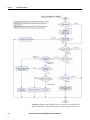
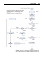
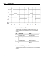
Message execution processes and timing diagrams .......................... 211
Message execution process (general) ........................................................ 211
Message execution sequence (general) ..................................................... 211
Message execution process (Rung = TRUE) .......................................... 212
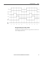
Message execution timing diagram (Rung = TRUE) ........................... 214
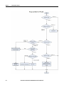
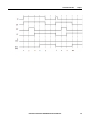
Message execution process (Rung = FALSE) ......................................... 215
Message execution timing diagram (Rung = FALSE)........................... 217
Message execution process (Error) ........................................................... 218
Message execution timing diagram (Error) ............................................. 218
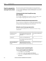
Using the communication (message) function blocks ..................... 220
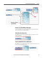
Configuring object data values for explicit messaging
(MSG_CIPGENERIC) ............................................................................. 220
Example: How to create a MSG_CIPGENERIC messaging program to
read data from a controller ......................................................................... 222
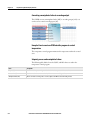
Example: How to create a MSG_CIPSYMBOLIC messaging program
to write a value to a variable ....................................................................... 232
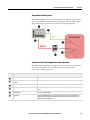
Example: How to configure Modbus communication to read from and
write to a drive .............................................................................................. 244
Communication protocol support .................................................. 249
Embedded communication channels ....................................................... 250
Chapter 10
Compare instructions
6
Equal ............................................................................................. 252
Greater than................................................................................... 254
Greater than or equal ..................................................................... 255
Less than ........................................................................................ 256
Less than or equal........................................................................... 257
Not equal ....................................................................................... 258
RockwellAutomationPublication2080-RM001B-EN-E-March2014
Table of Contents
Chapter 11
Counter instructions
CTD .............................................................................................. 260
CTU .............................................................................................. 262
CTUD ........................................................................................... 264
Chapter 12
Data conversion instructions
ANY_TO_BOOL .......................................................................... 268
ANY_TO_BYTE ........................................................................... 269
ANY_TO_DATE .......................................................................... 270
ANY_TO_DINT ........................................................................... 271
ANY_TO_DWORD...................................................................... 272
ANY_TO_INT .............................................................................. 273
ANY_TO_LINT ........................................................................... 274
ANY_TO_LREAL ......................................................................... 275
ANY_TO_LWORD ...................................................................... 276
ANY_TO_REAL ........................................................................... 277
ANY_TO_SINT ............................................................................ 278
ANY_TO_STRING ...................................................................... 279
ANY_TO_TIME ........................................................................... 280
ANY_TO_UDINT ........................................................................ 281
ANY_TO_UINT ........................................................................... 282
ANY_TO_ULINT ........................................................................ 283
ANY_TO_USINT ......................................................................... 284
ANY_TO_WORD......................................................................... 285
Chapter 13
Data manipulation
instructions
AVERAGE .................................................................................... 288
COP .............................................................................................. 290
COP operation status values ..................................................................... 293
Copying to a different data type ............................................................... 293
MIN .............................................................................................. 294
MAX ............................................................................................. 296
Chapter 14
High-Speed Counter (HSC)
instructions
What is a High-Speed Counter? ..................................................... 300
HSC .............................................................................................. 301
HSCCmd values .......................................................................................... 302
HSCAPP data type ..................................................................................... 303
RockwellAutomationPublication2080-RM001B-EN-E-March2014
7
Table of Contents
HSCSTS data type ...................................................................................... 310
PLS data type ................................................................................................ 318
HSC status codes (STS) ............................................................................. 320
HSC_SET_STS ............................................................................. 321
Using the High-Speed Counter instructions ................................... 324
Updating HSC application data ............................................................... 324
High-Speed Counter (HSC) User Interrupt dialog box ...................... 324
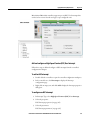
Configuring High-Speed Counter (HSC) user interrupts .................. 324
Add and configure a High-Speed Counter (HSC) User Interrupt .... 325
Configuring a Programmable Limit Switch (PLS) ................................ 328
Example: How to create a High-Speed Counter (HSC) program ..... 329
Add a Programmable Limit Switch (PLS) function.............................. 340
Example: Programmable Limit Switch (PLS) enabled ......................... 342
Chapter 15
Input/Output instructions
8
LCD .............................................................................................. 346
LCD_BKLT_REM ........................................................................ 349
LCD_BKLT_REM status codes .............................................................. 351
LCD_REM .................................................................................... 352
LCD_REM status codes ............................................................................ 356
RHC .............................................................................................. 357
RPC ............................................................................................... 359
DLG .............................................................................................. 360
DLG status codes ......................................................................................... 361
DLG error codes .......................................................................................... 362
IIM ................................................................................................ 363
IIM status codes ........................................................................................... 364
IOM .............................................................................................. 366
IOM status codes ......................................................................................... 368
KEY_READ .................................................................................. 369
KEY_READ_REM ........................................................................ 372
KEY_READ_REM operation .................................................................. 374
KEY_READ_REM status codes .............................................................. 374
KeyData bitfields table ............................................................................... 374
MM_INFO .................................................................................... 376
MMINFO data type ................................................................................... 377
PLUGIN_INFO ............................................................................ 379
PLUGIN_READ ........................................................................... 382
PLUGIN_READ status codes .................................................................. 383
PLUGIN_RESET .......................................................................... 385
PLUGIN_WRITE ......................................................................... 387
RockwellAutomationPublication2080-RM001B-EN-E-March2014
Table of Contents
RCP ............................................................................................... 389
RCP status codes ......................................................................................... 391
RCP error codes ........................................................................................... 391
RTC_READ .................................................................................. 393
RTC data type .............................................................................................. 394
RTC_SET...................................................................................... 396
RTC Set status values ................................................................................. 397
SYS_INFO .................................................................................... 398
SYS_INFO data type .................................................................................. 399
TRIMPOT_READ ........................................................................ 401
Trimpot ID definition ................................................................................ 402
Trimpot operation status values ............................................................... 402
Chapter 16
Interrupt instructions
STIS .............................................................................................. 406
UIC ............................................................................................... 408
UID ............................................................................................... 410
UIE................................................................................................ 412
UIF ................................................................................................ 414
Chapter 17
Motion control instructions
General rules for motion control function blocks ........................... 418
Motion control function block parameter details ........................... 421
Motion control axis states .......................................................................... 421
Motion control function block parameter numbers ............................. 423
Motion control function block error IDs ............................................... 424
Axis error scenarios ..................................................................................... 426
AXIS_REF data type .................................................................................. 426
Axis variables ................................................................................................ 427
MC_AbortTrigger ......................................................................... 429
MC_Halt ....................................................................................... 432
MC_Home .................................................................................... 436
Homing modes............................................................................................. 439
MC_MoveAbsolute........................................................................ 441
MC_MoveRelative ......................................................................... 446
MC_MoveVelocity......................................................................... 450
MC_Power .................................................................................... 455
MC_ReadAxisError ....................................................................... 460
AxisErrorID error codes ............................................................................. 462
MC_ReadBoolParameter ............................................................... 465
RockwellAutomationPublication2080-RM001B-EN-E-March2014
9
Table of Contents
MC_ReadParameter ...................................................................... 468
MC_ReadStatus ............................................................................. 471
MC_Reset ...................................................................................... 476
MC_SetPosition ............................................................................ 479
MC_Stop ....................................................................................... 483
MC_TouchProbe........................................................................... 487
Motion fixed input/output........................................................................ 491
MC_WriteBoolParameter.............................................................. 492
MC_WriteParameter ..................................................................... 496
Chapter 18
Process control instructions
DERIVATE ................................................................................... 502
HYSTER ....................................................................................... 504
INTEGRAL................................................................................... 506
PWM ............................................................................................. 512
PWM status codes ....................................................................................... 514
SCALER ........................................................................................ 516
STACKINT................................................................................... 519
TND .............................................................................................. 522
LIMIT ........................................................................................... 524
Chapter 19
Program control instruction
SUS ............................................................................................... 528
Chapter 20
Proportional Integral
Derivative (PID) instruction
10
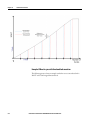
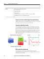
What is Proportional Integral Derivative (PID) control? ................ 532
How the IPIDController function block implements PID control . 533
IPIDCONTROLLER .................................................................... 535
GAIN_PID data type ................................................................................. 539
AT_Param data type ................................................................................... 540
IPIDController function block operation ...................................... 541
Using the Proportional Integral Derivative instruction .................. 543
Using auto-tune with the IPIDController function block .................. 543
Example: IPIDController with auto-tune .............................................. 550
Example: How to create a feedback loop for the manipulated value.. 552
Example: How to add a UDFB to a PID program ................................ 553
Example: How to create an IPIDController program to control
temperature................................................................................................... 554
RockwellAutomationPublication2080-RM001B-EN-E-March2014
Table of Contents
Example: How to create an IPIDController program to control water
supply level .................................................................................................... 556
Chapter 21
Real Time Clock (RTC)
instructions
RTC_READ .................................................................................. 562
RTC_SET...................................................................................... 564
RTC data type .............................................................................................. 565
RTC Set status values ................................................................................. 566
Chapter 22
String manipulation
instructions
ASCII ............................................................................................ 568
CHAR ........................................................................................... 570
DELETE........................................................................................ 572
FIND ............................................................................................. 574
INSERT ........................................................................................ 576
LEFT ............................................................................................. 578
MID .............................................................................................. 580
MLEN ........................................................................................... 582
RIGHT.......................................................................................... 584
REPLACE ..................................................................................... 586
Chapter 23
Timer instructions
Timer instruction configuration .................................................... 590
TOF............................................................................................... 591
TON .............................................................................................. 593
TONOFF ...................................................................................... 595
TP ................................................................................................. 598
DOY .............................................................................................. 600
DOYDATA data type ................................................................................ 601
TDF............................................................................................... 603
TOW ............................................................................................. 605
TOWDATA Data Type............................................................................ 607
Index
RockwellAutomationPublication2080-RM001B-EN-E-March2014
11
Preface
RockwellAutomationPublication2080-RM001B-EN-E-March2014
13
Preface
In This Manual
14
This guide provides reference information about the instruction set available for
developing programs for use in Micro800 control systems. The instruction set
includes Structured Text (ST), Ladder Diagram (LD) Function Block Diagram
(FBD) programming language support. Additionally, the ladder elements
supported in Connected Components Workbench development environment are
defined.
RockwellAutomationPublication2080-RM001B-EN-E-March2014
Preface
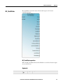
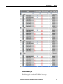
Supported Controllers
Connected Components Workbench™ includes configuration support for the
following Micro800™ controllers.
•
2080-LC10-12AWA
•
2080-LC30-24QBB
•
2080-LC10-12DWD
•
2080-LC30-24QVB
•
2080-LC10-12QBB
•
2080-LC30-24QWB
•
2080-LC10-12QWB
•
2080-LC30-48AWB
•
2080-LC20-20AWB
•
2080-LC30-48QBB
•
2080-LC20-20QBB
•
2080-LC30-48QVB
•
2080-LC20-20QWB
•
2080-LC30-48QWB
•
2080-LC30-10QVB
•
2080-LC50-24AWB
•
2080-LC30-10QWB
•
2080-LC50-24QBB
•
2080-LC30-16AWB
•
2080-LC50-24QVB
•
2080-LC30-16QVB
•
2080-LC50-24QWB
•
2080-LC30-16QWB
•
2080-LC50-48AWB
•
2080-LC50-48QBB
•
2080-LC50-48QVB
•
2080-LC50-48QWB
RockwellAutomationPublication2080-RM001B-EN-E-March2014
15
Preface
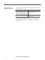
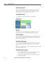
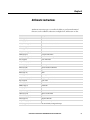
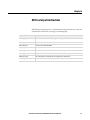
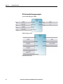
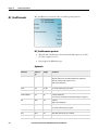
Additional Resources
These documents contain additional information concerning related Rockwell
Automation products.
Resource
Description
Industrial Automation Wiring and Grounding
Provides general guidelines for installing a Rockwell
Guidelines, publication 1770-4.1 available at
Automation industrial system.
http://literature.rockwellautomation.com/idc/grou
ps/literature/documents/in/1770-in041_-en-p.pdf.
Product Certifications website, http://www.ab.com
Provides declarations of conformity, certificates, and
other certification details.
You can view or download publications at
http://www.rockwellautomation.com/literature. To order paper copies of
technical documentation, contact your local Rockwell Automation distributor or
sales representative.
16
RockwellAutomationPublication2080-RM001B-EN-E-March2014
Chapter 1
Finding information about instructions and
ladder elements
Connected Components Workbench™ includes a comprehensive instruction set
with structures and arrays, development environments for ladder logic, structured
text, function block diagram, and user-defined function block programs .
Additionally, Connected Components Workbench includes user-interface
configuration tools for Micro800™ controllers, PowerFlex® drives, a Safety Relay
device, PanelView™ Component graphic terminals, and serial and network
connectivity options.
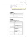
Instruction set
For information about a specific instruction, including a description, parameter
details, and language examples, locate the instruction from the table of contents, or
from the following reference topics.
Ladder Diagram elements
For a description of the ladder elements used in Connected Components
Workbench, see the following section:
RockwellAutomationPublication2080-RM001B-EN-E-March2014
17
Chapter 1
Finding informationabout instructionsand ladderelements
The Connected Components Workbench instruction set includes IEC 61131-3
compliant instruction blocks. Instruction blocks collectively include operators,
functions and function blocks.
Instruction blocks
•
Operators (on page 18)
•
Functions (on page 18)
•
Function blocks (on page 19)
Operators
An operator is a basic logical operation such as arithmetic, boolean, comparator, or
data conversion.
Functions
Functions have one or more input parameters and one output parameter.
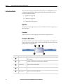
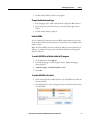
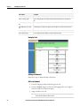
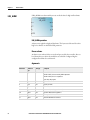
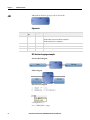
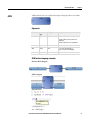
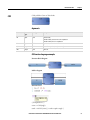
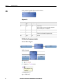
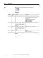
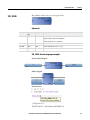
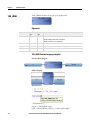
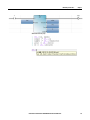
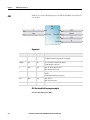
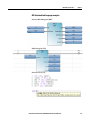
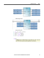
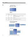
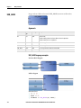
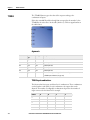
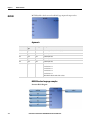
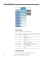
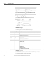
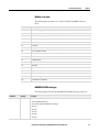
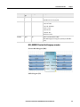
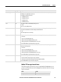
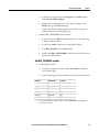
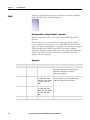
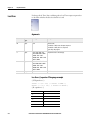
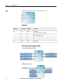
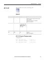
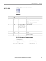
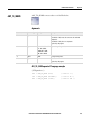
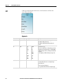
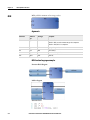
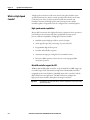
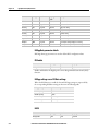
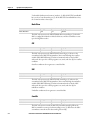
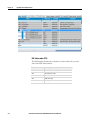
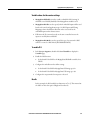
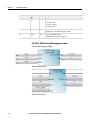
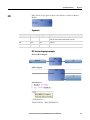
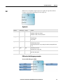
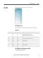
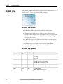
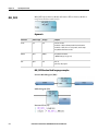
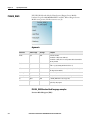
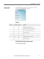
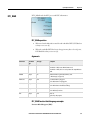
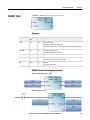
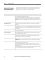
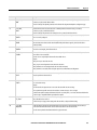
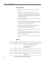
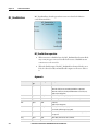
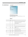
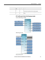
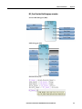
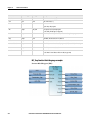
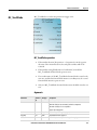
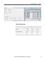
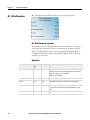
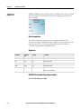
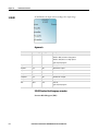
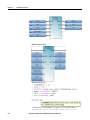
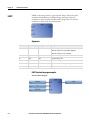
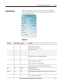
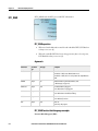
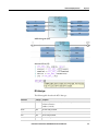
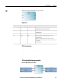
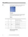
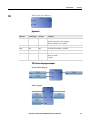
Instruction block format
An instruction block is represented by a single rectangle, and has a fixed number of
input connection points and output connection points. An elementary instruction
block performs a single function.
Item No.
18
Item
Description
Block name
The name of the function to be performed by the instruction block is written inside its rectangle
shape (at the top).
Input
Each input of an instruction block is labeled and has a defined type.
Input connection
Inputs are connected on the left border.
Output
Each output of an instruction block is labeled and has a defined type.
Output connection
Outputs are connected on the right border.
RockwellAutomationPublication2080-RM001B-EN-E-March2014March2014
Finding informationabout instructionsand ladderelements
Chapter 1
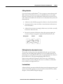
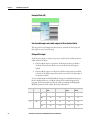
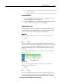
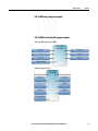
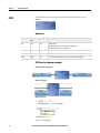
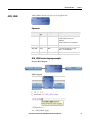
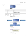
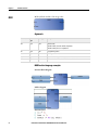
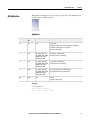
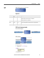
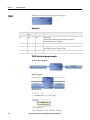
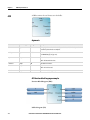
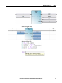
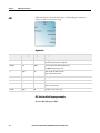
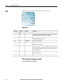
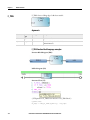
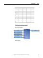
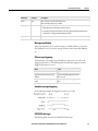
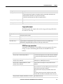
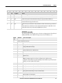
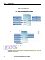
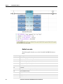
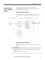
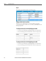
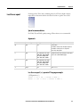
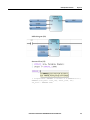
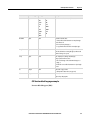
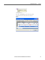
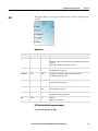
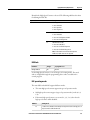
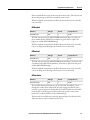
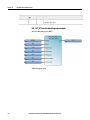
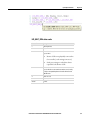
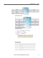
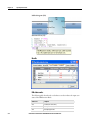
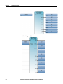
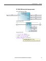
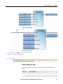
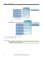
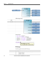
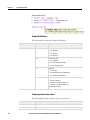
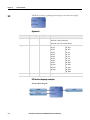
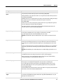
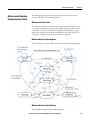
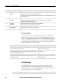
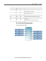
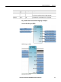
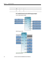
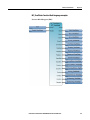
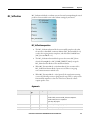
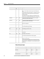
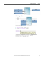
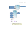
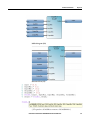
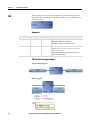
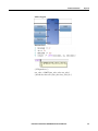
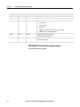
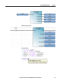
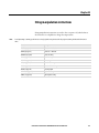
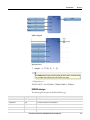
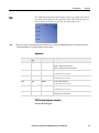
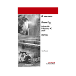
Calling a function
Connected Components WorkbenchTM does not support recursive function calls.
When a function of the Functions section is called by itself or one of its called
functions, a run-time error occurs. Furthermore, functions do not store the local
values of their local variables. Since functions are not instantiated, they cannot call
function blocks.
•
A function can be called by a program, by a function, or by a function block.
•
Any program of any section can call one or more functions. A function can
have local variables.
•
A function has no instance meaning local data is not stored and so is usually
lost from one call to the other.
•
Because the execution of a function is driven by its parent program, the
execution of the parent program is suspended until the function ends.
Main program
Function
Function
Defining function and parameter names
The interface of a function must be explicitly defined with a type and a unique
name for each of its calling (input) parameters or return (output) parameters. A
function has one return parameter. The value of a return parameter for a function
block is different for each programming language (FBD, LD, ST).
Function names and function parameter names can use up to 128 characters.
Function parameter names can begin with a letter or an underscore followed by
letters, numbers, and single underscores.
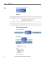
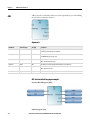
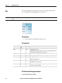
Function blocks
A function block is an instruction block that has input and output parameters and
works on internal data (parameters). It can be written in Structured Text, Ladder
Diagram, or Function Block Diagram languages.
RockwellAutomationPublication2080-RM001B-EN-E-March2014March2014
19
Chapter 1
Finding informationabout instructionsand ladderelements
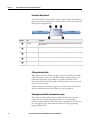
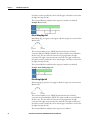
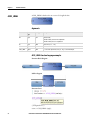
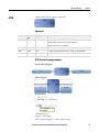
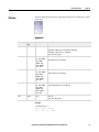
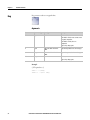
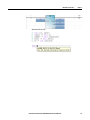
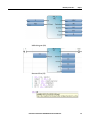
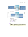
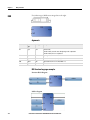
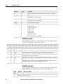
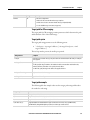
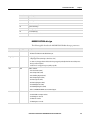
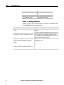
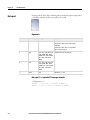
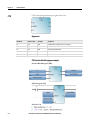
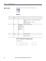
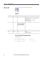
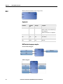
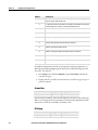
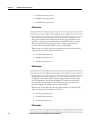
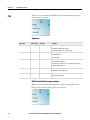
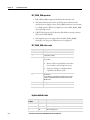
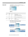
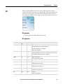
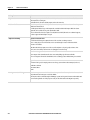
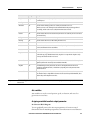
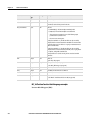
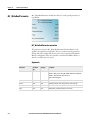
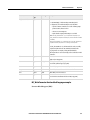
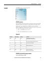
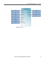
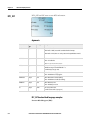
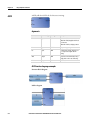
Instruction block format
An instruction block is represented by a single rectangle, and has a fixed number of
input connection points and output connection points. An elementary instruction
block performs a single function.
Item No.
Item
Description
Block name
The name of the function to be performed by the instruction block is written inside its rectangle
shape (at the top).
Input
Each input of an instruction block is labeled and has a defined type.
Input connection
Inputs are connected on the left border.
Output
Each output of an instruction block is labeled and has a defined type.
Output connection
Outputs are connected on the right border.
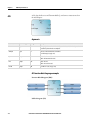
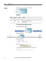
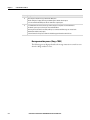
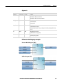
Calling a function block
When a function block is called in a program, an instance of the block is actually
called. The instance uses the same code, but the input and output parameters are
instantiated, which means local variables are copied for each instance of the
function block. The values of the variables of a function block instance are stored
from one cycle to the other.
A function block can be called by a program, or by another function block. They
cannot be called by functions because functions are not instantiated.
Defining function block and parameter names
The interface of a function block must be explicitly defined with a type and a
unique name for each of its calling (input) parameters or return (output)
parameters. Function blocks can have more than one output parameter. The value
of a return parameter for a function block is different for each programming
language (FBD, LD, ST).
20
RockwellAutomationPublication2080-RM001B-EN-E-March2014March2014
Finding informationabout instructionsand ladderelements
Chapter 1
Function block names and function block parameter names can use up to 128
characters. Function block parameter names can begin with a letter or an
underscore followed by letters, numbers, and single underscores.
RockwellAutomationPublication2080-RM001B-EN-E-March2014March2014
21
Chapter 1
Finding informationabout instructionsand ladderelements
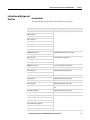
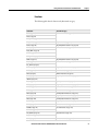
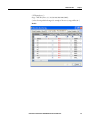
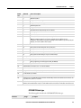
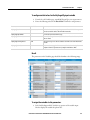
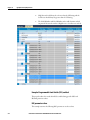
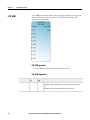
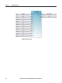
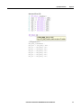
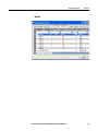
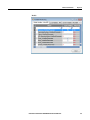
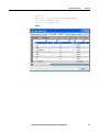
Instruction set in
alphabetical order
22
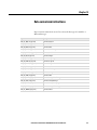
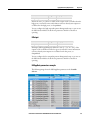
The following table lists the instruction set available in Connected Components
workbench in alphabetical order.
Instruction
Instruction block type
ABL (on page 114)
Function block
ABS (on page 66)
Function
ACB (on page 116)
Function block
ACL (on page 118)
Function block
ACOS (on page 68)
Function
ACOS_LREAL (on page 70)
Function
Addition (on page 72)
Operator
AHL (on page 120)
Function block
AND (on page 161)
Operator
AND_MASK (on page 136)
Function
ANY_TO_BOOL (on page 268)
Function
ANY_TO_BYTE (on page 269)
Function
ANY_TO_DATE (on page 270)
Function
ANY_TO_DINT (on page 271)
Function
ANY_TO_DWORD (on page 272)
Function
ANY_TO_INT (on page 273)
Function
ANY_TO_LINT (on page 274)
Function
ANY_TO_LREAL (on page 275)
Function
ANY_TO_LWORD (on page 276)
Function
ANY_TO_REAL (on page 277)
Function
ANY_TO_SINT (on page 278)
Function
ANY_TO_STRING (on page 279)
Function
ANY_TO_TIME (on page 280)
Function
ANY_TO_UDINT (on page 281)
Function
ANY_TO_UINT (on page 282)
Function
ANY_TO_ULINT (on page 283)
Function
ANY_TO_USINT (on page 284)
Function
ANY_TO_WORD (on page 285)
Function
ARD (on page 122)
Function block
ARL (on page 124)
Function block
ASCII (on page 568)
Function
ASIN (on page 73)
Function
ASIN_LREAL (on page 75)
Function
ATAN (on page 77)
Function
RockwellAutomationPublication2080-RM001B-EN-E-March2014March2014
Finding informationabout instructionsand ladderelements
Instruction
Instruction block type
ATAN_LREAL (on page 79)
Function
AVERAGE (on page 288)
Function block
AWA (on page 126)
Function
AWT (on page 128)
Function
CHAR (on page 570)
Function
COP (on page 290)
Function block
COS (on page 81)
Function
COS_LREAL (on page 83)
Function
CTD (on page 260)
Function
CTU (on page 262)
Function
CTUD (on page 264)
Function
DELETE (on page 572)
Function
DERIVATE (on page 502)
Function block
Division (on page 85)
Operator
DOY (on page 600)
Function
Equal (on page 252)
Operator
EXPT (on page 86)
Function
FIND (on page 574)
Function
F_TRIG (on page 154)
Function block
Greater Than (on page 254)
Operator
Greater Than or Equal (on page 255)
Operator
HSC (on page 301)
Function block
HSC_SET_STS (on page 321)
Function block
HYSTER (on page 504)
Function block
IIM (on page 363)
Function block
INSERT (on page 576)
Function
INTEGRAL (on page 506)
Function block
IOM (on page 366)
Function block
IPIDCONTROLLER (on page 535)
Function block
KEY_READ (on page 369)
Function block
LCD (on page 346)
Function
LEFT (on page 578)
Function
Less Than (on page 256)
Operator
Less Than or Equal (on page 257)
Operator
LIM_ALRM (on page 62)
Function block
LIMIT (on page 524)
Function
RockwellAutomationPublication2080-RM001B-EN-E-March2014March2014
Chapter 1
23
Chapter 1
24
Finding informationabout instructionsand ladderelements
Instruction
Instruction block type
LOG (on page 88)
Function
MAX (on page 296)
Function
MC_AbortTrigger (on page 429)
Function block
MC_Halt (on page 432)
Function block
MC_Home (on page 436)
Function block
MC_MoveAbsolute (on page 441)
Function block
MC_MoveRelative (on page 446)
Function block
MC_MoveVelocity (on page 450)
Function block
MC_Power (on page 455)
Function block
MC_ReadAxisError (on page 460)
Function block
MC_ReadBoolParameter (on page 465)
Function block
MC_ReadParameter (on page 468)
Function block
MC_ReadStatus (on page 471)
Function block
MC_Reset (on page 476)
Function block
MC_SetPosition (on page 479)
Function block
MC_Stop (on page 483)
Function block
MC_TouchProbe (on page 487)
Function block
MC_WriteBoolParameter (on page 492)
Function block
MC_WriteParameter (on page 496)
Function block
MID (on page 580)
Function
MIN (on page 294)
Function
MLEN (on page 582)
Function
MM_INFO (on page 376)
Function block
MOD (on page 90)
Function
MOV (on page 92)
Operator
MSG_CIPGENERIC (on page 178)
Function
MSG_CIPSYMBOLIC (on page 187)
Function
MSG_MODBUS (on page 197)
Function
MSG_MODBUS2 (on page 204)
Function
Multiplication (on page 93)
Operator
MUX4B (on page 174)
Function
MUX8B (on page 170)
Function
NOT (on page 163)
Operator
Not Equal (on page 258)
Operator
Neg (on page 94)
Operator
NOT_MASK (on page 138)
Function
RockwellAutomationPublication2080-RM001B-EN-E-March2014March2014
Finding informationabout instructionsand ladderelements
Instruction
Instruction block type
OR_MASK (on page 140)
Function
OR (on page 160)
Operator
PLUGIN_INFO (on page 379)
Function block
PLUGIN_READ (on page 382)
Function block
PLUGIN_RESET (on page 385)
Function block
PLUGIN_WRITE (on page 387)
Function block
POW (on page 95)
Function
R_TRIG (on page 156)
Function block
RAND (on page 97)
Function
REPLACE (on page 586)
Function
RHC (on page 357)
Function
RIGHT (on page 584)
Function
ROL (on page 142)
Function
ROR (on page 144)
Function
RPC (on page 359)
Function
RS (on page 158)
Function block
RTC_READ (on page 393)
Function block
RTC_SET (on page 396)
Function block
SCALER (on page 516)
Function block
SHL (on page 146)
Function
SHR (on page 148)
Function
SIN (on page 99)
Function
SIN_LREAL (on page 101)
Function
SQRT (on page 103)
Function
SR (on page 164)
Function block
STACKINT (on page 519)
Function block
STIS (on page 406)
Function
Subtraction (on page 105)
Operator
SUS (on page 528)
Function block
SYS_INFO (on page 398)
Function block
TAN (on page 106)
Function
TAN_LREAL (on page 108)
Function
TDF (on page 603)
Function
TND (on page 522)
Function
TOF (on page 591)
Function block
TON (on page 593)
Function block
RockwellAutomationPublication2080-RM001B-EN-E-March2014March2014
Chapter 1
25
Chapter 1
26
Finding informationabout instructionsand ladderelements
Instruction
Instruction block type
TONOFF (on page 595)
Function block
TOW (on page 605)
Function
TP (on page 598)
Function block
TRIMPOT_READ (on page 401)
Function block
TRUNC (on page 110)
Function
TTABLE (on page 166)
Function
UIC (on page 408)
Function
UID (on page 410)
Function
UIE (on page 412)
Function
UIF (on page 414)
Function
XOR_MASK (on page 150)
Function
XOR (on page 162)
Operator
RockwellAutomationPublication2080-RM001B-EN-E-March2014March2014
Finding informationabout instructionsand ladderelements
Chapter 1
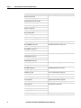
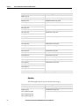
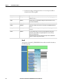
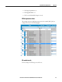
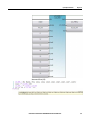
Instruction set by type and
Function blocks
function
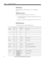
The following table lists the function blocks by functional category.
Instruction
Functional category
ABL (on page 114)
ASCII serial port instructions (on page 113)
ACB (on page 116)
ACL (on page 118)
AHL (on page 120)
ARD (on page 122)
ARL (on page 124)
AWA (on page 126)
AWT (on page 128)
AVERAGE (on page 288)
Data manipulation instructions (on page 287)
COP (on page 290)
CTD (on page 260)
Counter instructions (on page 259)
CTU (on page 262)
CTUD (on page 264)
DERIVATE (on page 502)
Process control instructions (on page 501)
F_TRIG (on page 154)
Boolean instructions (on page 153)
HSC (on page 301)
Input/Output instructions (on page 345)
HSC_SET_STS (on page 321)
HYSTER (on page 504)
Process control instructions (on page 501)
IIM (on page 363)
Input/Output instructions (on page 345)
INTEGRAL (on page 506)
Process control instructions (on page 501)
IOM (on page 366)
Input/Output instructions (on page 345)
IPIDCONTROLLER (on page 535)
Proportional Integral Derivative (PID) instruction (on page
531)
KEY_READ (on page 369)
Input/Output instructions (on page 345)
LIM_ALRM (on page 62)
Alarm instructions (see "Alarm instruction" on page 61)
MC_AbortTrigger (on page 429)
Motion control instructions (on page 417)
MC_Halt (on page 432)
MC_Home (on page 436)
MC_MoveAbsolute (on page 441)
MC_MoveRelative (on page 446)
MC_MoveVelocity (on page 450)
RockwellAutomationPublication2080-RM001B-EN-E-March2014March2014
27
Chapter 1
Finding informationabout instructionsand ladderelements
Instruction
Functional category
MC_Power (on page 455)
MC_ReadAxisError (on page 460)
MC_ReadBoolParameter (on page 465)
MC_ReadParameter (on page 468)
MC_ReadStatus (on page 471)
MC_Reset (on page 476)
MC_SetPosition (on page 479)
MC_Stop (on page 483)
MC_TouchProbe (on page 487)
MC_WriteBoolParameter (on page 492)
MC_WriteParameter (on page 496)
MM_INFO (on page 376)
Input/Output instructions (on page 345)
MSG_CIPGENERIC (on page 178)
Communication instructions (on page 177)
MSG_CIPSYMBOLIC (on page 187)
MSG_MODBUS (on page 197)
MSG_MODBUS2 (on page 204)
PLUGIN_INFO (on page 379)
Input/Output instructions (on page 345)
PLUGIN_READ (on page 382)
PLUGIN_RESET (on page 385)
PLUGIN_WRITE (on page 387)
R_TRIG (on page 156)
Boolean instructions (on page 153)
RS (on page 158)
RTC_READ (on page 393)
Input/Output instructions (on page 345)
RTC_SET (on page 396)
SCALER (on page 516)
Process control instructions (on page 501)
SR (on page 164)
Boolean instructions (on page 153)
STACKINT (on page 519)
Process control instructions (on page 501)
SUS (on page 528)
Program control instruction (on page 527)
SYS_INFO (on page 398)
Input/Output instructions (on page 345)
TOF (on page 591)
Timer instructions (on page 589)
TON (on page 593)
TONOFF (on page 595)
TP (on page 598)
TRIMPOT_READ (on page 401)
28
Input/Output instructions (on page 345)
RockwellAutomationPublication2080-RM001B-EN-E-March2014March2014
Finding informationabout instructionsand ladderelements
Chapter 1
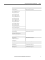
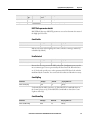
Functions
The following table lists the functions by functional category.
Instruction
Functional category
ABS (on page 66)
Arithmetic instructions (on page 65)
ACOS (on page 68)
ACOS_LREAL (on page 70)
AND_MASK (on page 136)
Binary instructions (on page 135)
ASCII (on page 568)
String manipulation instructions (on page 567)
ASIN (on page 73)
Arithmetic instructions (on page 65)
ASIN_LREAL (on page 75)
ATAN (on page 77)
ATAN_LREAL (on page 79)
CHAR (on page 570)
String manipulation instructions (on page 567)
COS (on page 81)
Arithmetic instructions (on page 65)
COS_LREAL (on page 83)
DELETE (on page 572)
String manipulation instructions (on page 567)
DOY (on page 600)
Timer instructions (on page 589)
EXPT (on page 86)
Arithmetic instructions (on page 65)
FIND (on page 574)
String manipulation instructions (on page 567)
INSERT (on page 576)
LCD (on page 346)
Input/Output instructions (on page 345)
LEFT (on page 578)
String manipulation instructions (on page 567)
LIMIT (on page 524)
Process control instructions (on page 501)
LOG (on page 88)
Arithmetic instructions (on page 65)
MAX (on page 296)
Data manipulation instructions (on page 287)
MID (on page 580)
String manipulation instructions (on page 567)
MIN (on page 294)
Data manipulation instructions (on page 287)
MLEN (on page 582)
String manipulation instructions (on page 567)
MOD (on page 90)
Arithmetic instructions (on page 65)
MUX4B (on page 174)
Boolean instructions (on page 153)
MUX8B (on page 170)
NOT_MASK (on page 138)
Binary instructions (on page 135)
OR_MASK (on page 140)
POW (on page 95)
Arithmetic instructions (on page 65)
RockwellAutomationPublication2080-RM001B-EN-E-March2014March2014
29
Chapter 1
Finding informationabout instructionsand ladderelements
Instruction
Functional category
RAND (on page 97)
REPLACE (on page 586)
String manipulation instructions (on page 567)
RHC (on page 357)
Input/Output instructions (on page 345)
RIGHT (on page 584)
String manipulation instructions (on page 567)
ROL (on page 142)
Binary instructions (on page 135)
ROR (on page 144)
RPC (on page 359)
Input/Output instructions (on page 345)
SHL (on page 146)
Binary instructions (on page 135)
SHR (on page 148)
SIN (on page 99)
Arithmetic instructions (on page 65)
SIN_LREAL (on page 101)
SQRT (on page 103)
STIS (on page 406)
Interrupt instructions (on page 405)
TAN (on page 106)
Arithmetic instructions (on page 65)
TAN_LREAL (on page 108)
TDF (on page 603)
Timer instructions (on page 589)
TND (on page 522)
Process control instructions (on page 501)
TOW (on page 605)
Timer instructions (on page 589)
TRUNC (on page 110)
Arithmetic instructions (on page 65)
TTABLE (on page 166)
Boolean instructions (on page 153)
UIC (on page 408)
Interrupt instructions (on page 405)
UID (on page 410)
UIE (on page 412)
UIF (on page 414)
XOR_MASK (on page 150)
Binary instructions (on page 135)
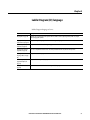
Operators
The following table lists the operators by functional category.
Instruction
Functional category
Addition (on page 72)
Arithmetic instructions (on page 65)
AND (on page 161)
Boolean instructions (on page 153)
ANY_TO_BOOL (on page 268)
Data conversion instructions (on page 267)
ANY_TO_BYTE (on page 269)
ANY_TO_DATE (on page 270)
30
RockwellAutomationPublication2080-RM001B-EN-E-March2014March2014
Finding informationabout instructionsand ladderelements
Instruction
Functional category
Addition (on page 72)
Arithmetic instructions (on page 65)
Chapter 1
ANY_TO_DINT (on page 271)
ANY_TO_DWORD (on page 272)
ANY_TO_INT (on page 273)
ANY_TO_LINT (on page 274)
ANY_TO_LREAL (on page 275)
ANY_TO_LWORD (on page 276)
ANY_TO_REAL (on page 277)
ANY_TO_SINT (on page 278)
ANY_TO_STRING (on page 279)
ANY_TO_TIME (on page 280)
ANY_TO_UDINT (on page 281)
ANY_TO_UINT (on page 282)
ANY_TO_ULINT (on page 283)
ANY_TO_USINT (on page 284)
ANY_TO_WORD (on page 285)
Division (on page 85)
Arithmetic instructions (on page 65)
Equal (on page 252)
Compare instructions (on page 251)
Greater Than (on page 254)
Greater Than or Equal (on page 255)
Less Than (on page 256)
Less Than or Equal (on page 257)
MOV (on page 92)
Arithmetic instructions (on page 65)
Multiplication (on page 93)
Neg (on page 94)
NOT (on page 163)
Boolean instructions (on page 153)
Not Equal (on page 258)
Compare instructions (on page 251)
OR (on page 160)
Boolean instructions (on page 153)
Subtraction (on page 105)
Arithmetic instructions (on page 65)
XOR (on page 162)
Boolean instructions (on page 153)
RockwellAutomationPublication2080-RM001B-EN-E-March2014March2014
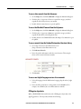
31
Chapter 2
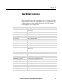
Ladder Diagram (LD) language
Ladder Diagram language reference.
Element
Description
LD program (on page 34)
Graphical representation of Boolean equations which combines contacts (input arguments) with coils (output
results) using graphic symbols.
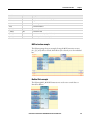
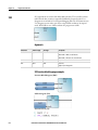
LD program development Example showing the language editor for an Ladder Diagram (LD) program.
environment (on page 35)
Ladder Diagram (LD)
elements (on page 37)
Components used to build a Ladder Diagram program.
Instruction blocks in LD
programs (on page 53)
IEC 61131-3 compliant instruction blocks collectively include function blocks, functions and operators.
Working in the LD
language editor (on page
54)
Adding elements to a LD program.
Ladder Diagram (LD)
program examples (on
page 56)
Examples of Ladder Diagram (LD) programs.
LD Keyboard shortcuts (on Keyboard shortcuts available for the Ladder Diagram (LD) language.
page 58)
RockwellAutomationPublication2080-RM001B-EN-E-March2014March2014
33
Chapter 2
LadderDiagram(LD) language
LD program
A Ladder Diagram (LD) is a graphical representation of Boolean equations that
combines contacts (input arguments) with coils (output results). Using graphic
symbols in a program chart (organized like a relay ladder wiring diagram), the LD
language describes the tests and modifications of Boolean data.
LD graphic symbols are organized within the chart as an electrical contact
diagram. The term "ladder" comes from the concept of rungs connected to vertical
power rails at both ends where each rung represents an individual circuit.
Connected Components Workbench™ support for Ladder Diagram (LD)
Connected Components Workbench™ provides an LD language editor and
supports the elements and instructions that are supplied with the Connected
Components Workbench software only.
34
RockwellAutomationPublication2080-RM001B-EN-E-March2014March2014
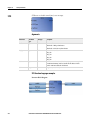
LadderDiagram(LD) language
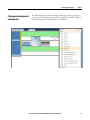
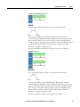
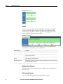
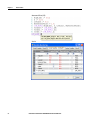
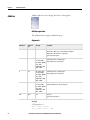
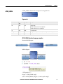
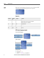
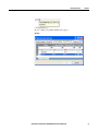
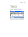
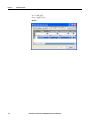
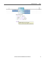
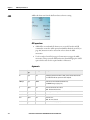
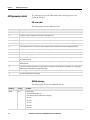
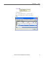
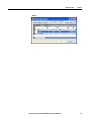
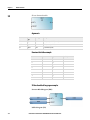
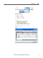
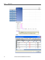
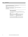
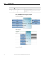
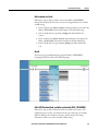
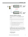
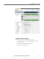
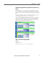
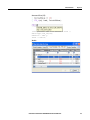
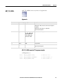
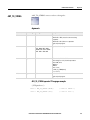
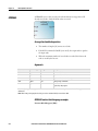
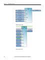
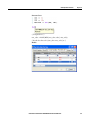
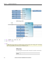
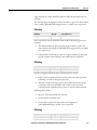
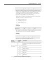
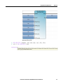
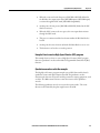
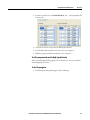
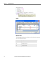
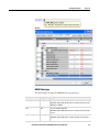
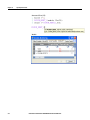
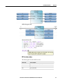
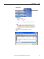
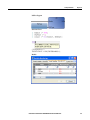
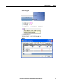
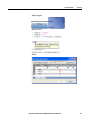
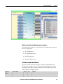
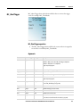
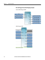
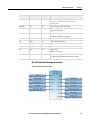
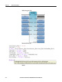
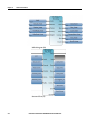
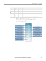
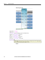
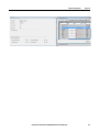
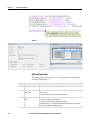
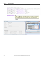
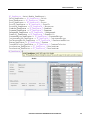
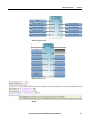
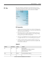
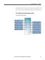
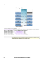
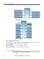
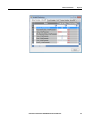
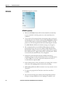
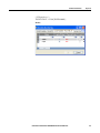
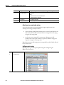
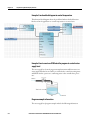
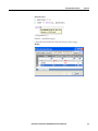
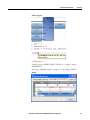
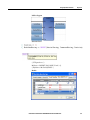
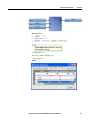
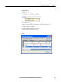
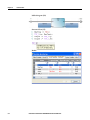
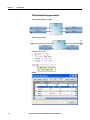
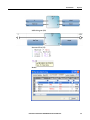
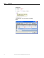
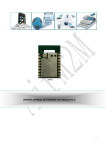
LD program development
environment
Chapter 2
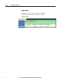
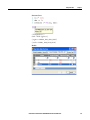
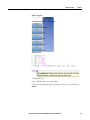
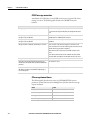
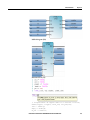
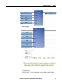
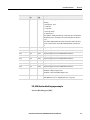
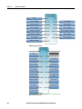
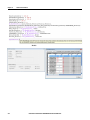
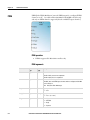
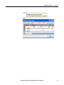
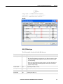
The following illustration shows the language editor for an LD program where
you develop an LD Program Organizational Unit (POU). Use the LD Toolbox or
LD keyboard shortcuts to add elements to your LD POU.
RockwellAutomationPublication2080-RM001B-EN-E-March2014March2014
35
Chapter 3
Ladder Diagram (LD) elements
Ladder diagram elements are the components that you use to build a ladder
diagram program. All the elements listed in the following table can be added to
your ladder diagram from the LD Toolbox within Connected Components
Workbench.
Element
Description
Rung (on page 37)
Represents a group of circuit elements that lead to the activation of a coil.
Block (LD) (on page 40)
Instructions include operators, functions, and function blocks including user-defined function blocks.
Branch (on page 39)
Two or more instructions in parallel.
Coil (on page 43)
Represents the assignment of outputs or internal variables. In an LD program, a coil represents an action.
Contact (on page 48)
Represents the value or function of an input or internal variable.
Return (on page 51)
Represents the conditional end of a diagram output.
Jump (on page 51)
Represents the conditional and unconditional logic in the LD program that control the control the execution of
diagrams.
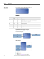
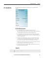
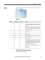
Rung
Rungs are graphic components of an LD diagram that represent a group of circuit
elements that lead to the activation of a coil. Rungs can have labels to identify
them within the diagram. Labels, along with jumps, control the execution of a
diagram. You can enter comments (free-format text) above the rung for
documentation purposes.
Change the default width of rungs
Follow these steps to use a new width for rungs. You cannot adjust the width of
existing rungs within a project.
1. From the Tools menu, select Options.
2. Click IEC Languages, and then Ladder Diagram.
3. Under View Settings, click Default Cell Width.
4. Increase the cell width value, and then click OK.
5. Create and open a new LD program.
6. Hold down the Ctrl key while rolling the thumb wheel down on your
mouse until the entire rung is visible on your computer.
RockwellAutomationPublication2080-RM001B-EN-E-March2014
37
Chapter 3
LadderDiagram(LD)elements
Rung comments
Comments you enter in the space above the rung are saved in rich text format and
stored in the controller.
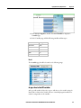
1. In the Language Editor, double-click the rectangular area above the rung,
then type comments.
2. Click anywhere in the Language Editor workspace to save the comments.
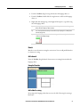
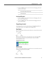
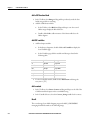
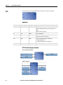
Add a label to a rung
Every rung in the language editor has an area to the left of the rung for entering a
label name.
Label name requirements
Labels can be an unlimited number of characters, beginning with a letter or
underscore character followed by letters, numbers, and underscore characters.
Labels cannot have spaces or special characters (for example, ’+’, ’-’, or ’\’).
To add a label for a rung
•
Click the area to the left of the rung, then type a label name.
Example: Label
To add an element to an LD program
To add a rung to the LD language editor, do one of the following:
38
RockwellAutomationPublication2080-RM001B-EN-E-March2014March2014
LadderDiagram(LD)elements
Chapter 3
•
From the Toolbox, drag the rung element into the language editor, or
•
From the Toolbox, double-click the rung element to add it to the language
editor, or
•
Right-click and existing rung, select Copy and then paste a copy of the rung
into the language editor.
Tip:
A plus sign (+) appears on top of a Toolbox element when you hover over a valid target.
Release the mouse button to add the element.
Tip:
You can use keyboard shortcut keys to add elements to your LD program. See LD Keyboard
shortcuts (on page 58).
Tip:
If your ladder diagram contains more than 355 rungs, use the down triangle rather than the
scroll bar to view additional rungs.
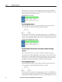
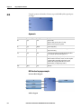
Branch
Branches create alternative routing for connections. You can add parallel branches
to elements on a rung.
Add a branch
From the Toolbox, drag the branch element onto an existing element within the
language editor.
Example: Branches
Add a label to a rung
Every rung in the language editor has an area to the left of the rung for entering a
label name.
RockwellAutomationPublication2080-RM001B-EN-E-March2014March2014
39
Chapter 3
LadderDiagram(LD)elements
Label name requirements
Labels can be an unlimited number of characters, beginning with a letter or
underscore character followed by letters, numbers, and underscore characters.
Labels cannot have spaces or special characters (for example, ’+’, ’-’, or ’\’).
To add a label for a rung
•
Click the area to the left of the rung, then type a label name.
Example: Label
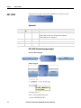
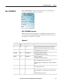
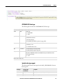
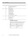
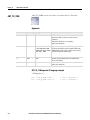
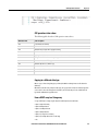
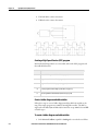
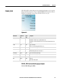
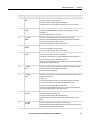
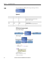
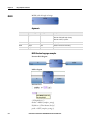
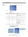
Block (LD)
A LD block element is a functional element in a LD diagram that can be a
function block, a function, a user-defined function block, or an operator.
LD instruction blocks
The Connected Components Workbench instruction set includes IEC 61131-3
compliant instruction blocks. Instruction blocks collectively include operators,
functions and function blocks.
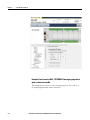
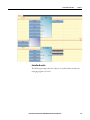
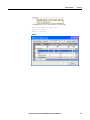
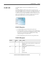
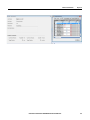
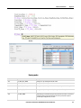
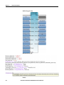
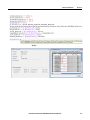
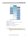
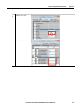
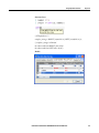
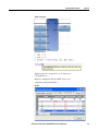
Add a Block to an LD program
Use the LD Toolbox to add a Block to an LD program. After you add the Block,
you can configure its variables from the Block selector or from the Variable
selector.
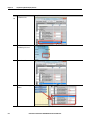
Follow these steps to add a block element to an LD program, or change an existing
block element to a different type.
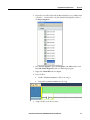
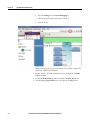
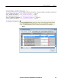
Add a block element to a program
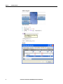
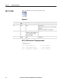
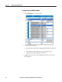
1. From the Toolbox, drag the block element into the language editor and
place it in the correct location to display the Block Selector.
2. In Search type the name of the block you want to add or sort and scroll
through the list to find it.
40
RockwellAutomationPublication2080-RM001B-EN-E-March2014March2014
LadderDiagram(LD)elements
Chapter 3
3. Double-click the block to add it to the program.
Change the block element type
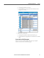
1. In the language editor, double-click the block to display the Block Selector.
2. In Search type the name of the block or sort and scroll through the list to
find it.
3. Double-click the block to update it.
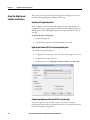
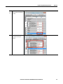
Enable EN/ENO
You can enable the EN input parameter and ENO output parameter so they will
always be added with the instruction block even when there is an available boolean
input or output.
Note: The EN and ENO parameters will only be added to instruction blocks you
add after you enable the setting - instructions blocks already in the LD program
will not be affected.
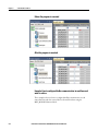
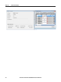
To enable EN/ENO for all blocks added to LD program
1. On the Tool menu, click Options.
2. Select IEC Languages > Ladder Diagram (LD) to display the language
editor properties.
3. In Block Settings, set Enable EN/ENO to True.
4. Click OK.
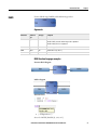
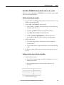
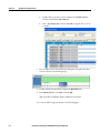
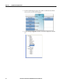
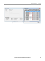
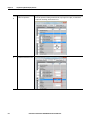
To enable EN/ENO for the block
1. After selecting a block in the Block Selector, select EN/ENO (located at the
bottom of the list).
2. In the Block Selector, after selecting at the bottom of the list of instructions,
select EN/ENO.
RockwellAutomationPublication2080-RM001B-EN-E-March2014March2014
41
Chapter 3
LadderDiagram(LD)elements
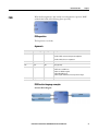
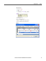
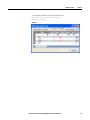
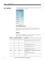
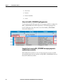
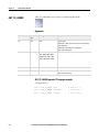
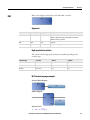
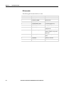
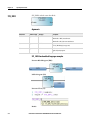
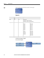
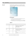
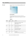
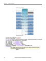
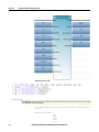
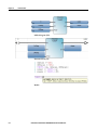
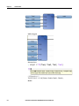
Example: Block (LD)
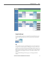
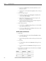
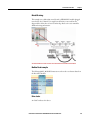
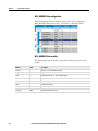
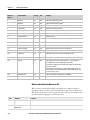
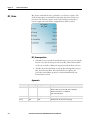
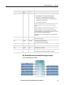
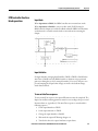
Use of enable inputs and enable outputs in LD instruction blocks
The rung state in an LD diagram is always boolean, and a block's first input and
first output is connected to the rung.
EN input/EN output
If a first boolean input or output is not present, an EN and/or an ENO parameter
will be added to the block.
•
If the first block input is not boolean, an EN input parameter is added to
the block. The instruction block is executed only when the EN input is
TRUE.
•
If the first block output is not boolean, an ENO output parameter is added
to the block. The ENO output always has the same state as the first input of
the instruction block.
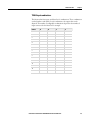
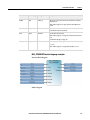
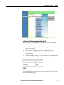
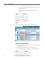
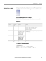
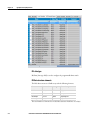
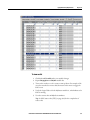
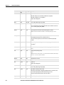
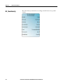
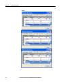
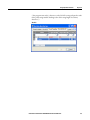
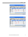
You can enable/disable the EN/ENO block settings for an individual instruction
block in the Block Selector, or in Block Settings for the Ladder Diagram (LD)
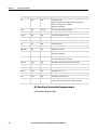
program. The following table describes the results of enabling and disabling the
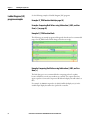
EN/ENO parameters in the blocks shown in the illustration.
Rung
EN/ENO
1
False
2
42
True
Block
1st boolean
input
EN input added? 1st boolean
output
ENO output
added?
<=
No
Yes
Yes
No
ACB
Yes
No
Yes
No
<=
No
Yes
Yes
Yes
ACB
Yes
Yes
Yes
Yes
RockwellAutomationPublication2080-RM001B-EN-E-March2014March2014
LadderDiagram(LD)elements
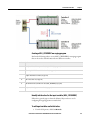
Chapter 3
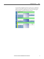
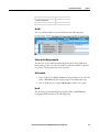
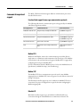
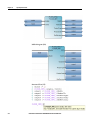
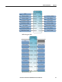
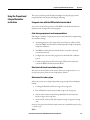
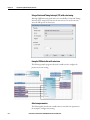
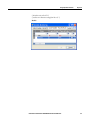
Example: Enable input
In some cases, Enable parameters are required for instruction blocks that execute
on call. The following example shows an SUS instruction block with an Enable
input.
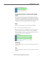
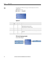
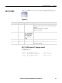
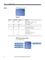
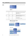
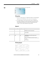
Coil
Coils are graphic components of an LD diagram that represent the assignment of
an output or of an internal variable. In an LD diagram, a coil represents an action.
A coil must be connected on the left to a Boolean symbol, such as a contact, or to a
Boolean output of an instruction block. Consequently, coils can only be added to a
defined rung in the LD language editor. After a coil is added, its definition can be
modified.
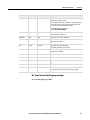
You can add the following coil element types to your LD program from the
Toolbox.
RockwellAutomationPublication2080-RM001B-EN-E-March2014March2014
43
Chapter 3
LadderDiagram(LD)elements
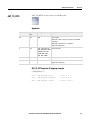
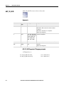
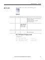
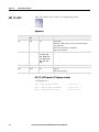
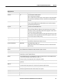
Coil element
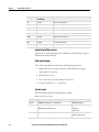
Description
Direct coil (on page 45)
Direct coils support a Boolean output of a connection line Boolean state.
Reverse coil (on page 45)
Reverse coils support a Boolean output according to the Boolean negation of a connection line
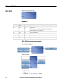
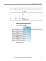
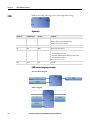
state.
Pulse rising edge coil (on page
46)
Pulse rising edge (or positive) coils support a Boolean output of a connection line Boolean state.
Pulse falling edge coil (on page
46)
Pulse falling edge (or negative) coils support a Boolean output of a connection line Boolean state.
Set coil (on page 47)
Set coils support a Boolean output of a connection line Boolean state.
Reset coil (on page 47)
Reset coils support a Boolean output of a connection line Boolean state.
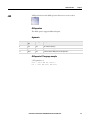
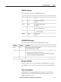
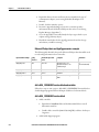
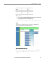
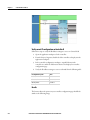
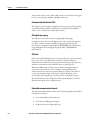
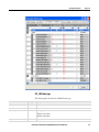
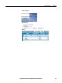
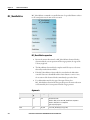
Example: Coils
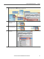
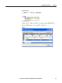
Adding coil elements
Follow these steps to add and modify coil elements.
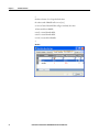
Add a coil element
1. Verify the LD program has a defined rung for the coil.
2. From the Toolbox, drag the coil into the LD language editor to the right of
a Boolean symbol or of a Boolean output.
3. Assign a variable to the coil.
Tip:
44
A plus sign (+) appears on top of a Toolbox element when you hover over a valid target.
Release the mouse button to add the element.
RockwellAutomationPublication2080-RM001B-EN-E-March2014March2014
LadderDiagram(LD)elements
Tip:
Chapter 3
You can use keyboard shortcut keys to add elements to your LD program. See LD Keyboard
shortcuts (on page 58).
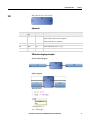
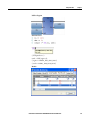
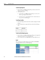
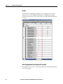
Insert a parallel coil
1. From the Toolbox, drag the branch element into the language editor, and
place it just slightly above the rung element.
2. From the Toolbox, drag a coil element into the language editor, and place it
on the branch element to display the coil on the branch.
Change the type of coil
In the language editor, select the coil, then press the space bar until the new coil
type is available. Every time the space bar is pressed the type changes from direct,
to reverse, to set, to reset, to pulse rising edge, to pulse falling edge.
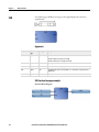
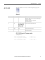
Direct Coil
A direct coil supports a Boolean output of a connection line Boolean state.
The associated variable is assigned with the Boolean state of the left connection.
The state of the left connection is propagated into the right connection. The right
connection must be connected to the right vertical power rail (unless you have
parallel coils, where only the upper coil must be connected to the right vertical
power rail).
The associated Boolean variable must be an output or it must be user-defined.
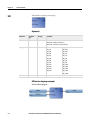
Example: Direct coil
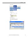
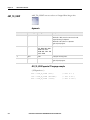
Reverse Coil
A reverse coil element supports a Boolean output according to the Boolean
negation of a connection line state.
The associated variable is assigned with the Boolean negation of the state of the
left connection. The state of the left connection is propagated into the right
connection. The right connection must be connected to the right vertical power
RockwellAutomationPublication2080-RM001B-EN-E-March2014March2014
45
Chapter 3
LadderDiagram(LD)elements
rail (unless you have parallel coils, where only the upper coil must be connected to
the right vertical power rail).
The associated Boolean variable must be output or it must be user-defined.
Example: Reverse Coil
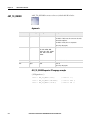
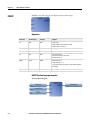
Pulse Falling Edge Coil
Pulse falling edge (or negative) coils support a Boolean output of a connection line
Boolean state.
The associated variable is set to TRUE when the Boolean state of the left
connection falls from TRUE to FALSE. The output variable resets to FALSE in
all other cases. The state of the left connection is propagated into the right
connection. The right connection must be connected to the right vertical power
rail (unless you have parallel coils, where only the upper coil must be connected to
the right vertical power rail).
The associated Boolean variable must be output or it must be user-defined.
Example: Pulse Falling Edge Coil
Pulse Rising Edge Coil
Pulse rising edge (or positive) coils support a Boolean output of a connection line
Boolean state.
The associated variable is set to TRUE when the Boolean state of the left
connection rises from FALSE to TRUE. The output variable resets to FALSE in
all other cases. The state of the left connection is propagated into the right
connection. The right connection must be connected to the right vertical power
rail (unless you have parallel coils, where only the upper coil must be connected to
the right vertical power rail).
The associated Boolean variable must be output or user-defined.
46
RockwellAutomationPublication2080-RM001B-EN-E-March2014March2014
LadderDiagram(LD)elements
Chapter 3
Example: Pulse Rising Edge Coil
Set Coil
Set coils support a Boolean output of a connection line Boolean state.
The associated variable is set to TRUE when the Boolean state of the left
connection becomes TRUE. The output variable keeps this value until an inverse
order is made by a Reset coil. The state of the left connection is propagated into
the right connection. The right connection must be connected to the right vertical
power rail (unless you have parallel coils, where only the upper coil must be
connected to the right vertical power rail).
The associated Boolean variable must be output or it must be user-defined.
Example: Set Coil
Reset Coil
Reset coils support a Boolean output of a connection line Boolean state.
The associated variable is reset to FALSE when the Boolean state of the left
connection becomes TRUE. The output variable keeps this value until an inverse
order is made by a Set coil. The state of the left connection is propagated into the
right connection. The right connection must be connected to the right vertical
power rail (unless you have parallel coils, where only the upper coil must be
connected to the right vertical power rail).
The associated Boolean variable must be output or user-defined.
RockwellAutomationPublication2080-RM001B-EN-E-March2014March2014
47
Chapter 3
LadderDiagram(LD)elements
Example: Reset Coil
Contact
Contacts are graphic components of an LD diagram. Depending on the type, a
contact represents the value or function of an input or of an internal variable.
Contacts can only be added to a defined rung in the LD language editor. After a
contact is added, its definition can be modified.
Example: Contacts
You can add the following contact element types to your LD program from the
LD Toolbox in Connected Components Workbench.
Contact element
Description
Direct contact (on page 49)
Direct contacts support a Boolean operation between a connection line state and a Boolean variable.
Reverse contact (on page 49)
Reverse contacts support a Boolean operation between a connection line state and the Boolean
negation of a Boolean variable.
Pulse rising edge contact (on
page 50)
Pulse rising edge (or positive) contacts support a Boolean operation between a connection line state
and the rising edge of a Boolean variable.
Pulse falling edge contact
Pulse falling edge (negative) contacts enable a Boolean operation between a connection line state and
the falling edge of a Boolean variable.
Adding contact elements
Follow these steps to add a contact element to the ladder rung or change the type
of contact used.
Add a contact element
1. Verify the LD program has a defined rung for the contact.
48
RockwellAutomationPublication2080-RM001B-EN-E-March2014March2014
LadderDiagram(LD)elements
Chapter 3
2. From the Toolbox, drag the contact element into the language editor and
position it on the rung.
Tip:
A plus sign (+) appears on top of a Toolbox element when you hover over a valid target.
Release the mouse button to add the element.
Tip:
You can use keyboard shortcut keys to add elements to your LD program. See LD Keyboard
shortcuts (on page 58).
Insert a parallel contact
1. From the Toolbox, drag the branch element into the language editor, and
place it on the existing contact.
2. From the Toolbox, drag a contact element into the language editor, and
place it on the branch.
Change the type of contact
In the language editor, select the contact, then press the space bar until the the
contact type you want to use is displayed in the language editor.
Direct Contact
Direct contacts support a Boolean operation between a connection line state and a
Boolean variable.
The state of the connection line on the right of the contact is the logical AND
between the state of the left connection line and the value of the variable
associated with the contact.
Example: Direct Contact
Reverse Contact
Reverse contacts support a Boolean operation between a connection line state and
the Boolean negation of a Boolean variable.
RockwellAutomationPublication2080-RM001B-EN-E-March2014March2014
49
Chapter 3
LadderDiagram(LD)elements
The state of the connection line on the right of the contact is the logical AND
between the state of the left connection line and the Boolean negation of the value
of the variable associated with the contact.
Example: Reverse Contact
Pulse Rising Edge Contact
Pulse rising edge (or positive) contacts support a Boolean operation between a
connection line state and the rising edge of a Boolean variable.
The state of the connection line on the right of the contact is set to TRUE when
the state of the connection line on the left is TRUE, and the state of the associated
variable rises from FALSE to TRUE. The state is reset to FALSE in all other cases.
Example: Pulse Rising Edge Contact
Recommendation: Restrict the use of output variables with edge
contacts
We recommend you do not use outputs or variables with a Pulse rising edge
contact (positive) or a Pulse falling edge contact (negative). These contacts are for
physical inputs in a ladder diagram. If you need to detect the edge of a variable or
an output, we recommend you use the R_TRIG/F_TRIG function block, which
is supported and works in any language at any location in your program.
Pulse Falling Edge Contact
Pulse falling edge (or negative) contacts support a Boolean operation between a
connection line state and the falling edge of a Boolean variable.
The state of the connection line on the right of the contact is set to TRUE when
the state of the connection line on the left is TRUE, and the state of the associated
variable falls from TRUE to FALSE. The state is reset to FALSE in all other cases.
50
RockwellAutomationPublication2080-RM001B-EN-E-March2014March2014
LadderDiagram(LD)elements
Chapter 3
Example: Pulse Falling Edge Contact
Recommendation: Restrict the use of output variables with edge
contacts
We recommend you do not use outputs or variables with a Pulse rising edge
contact (positive) or a Pulse falling edge contact (negative). These contacts are for
physical inputs in a ladder diagram. If you need to detect the edge of a variable or
an output, we recommend you use the R_TRIG/F_TRIG function block, which
is supported and works in any language at any location in your program.
Return
Returns are outputs that represent a conditional end of an LD diagram.
Note:
You cannot place connections to the right of a return element.
When the left connection line has the TRUE Boolean state, the diagram ends
without executing the instructions located on the next lines of the diagram.
When the LD diagram is a function, its name is associated with an output coil to
set the return value (returned to the calling diagram).
Example: Return
Insert a return
From the Toolbox, drag the return element into the language editor and place it
on the rung.
Jump
Jumps are conditional or unconditional elements that control the execution of an
LD diagram.
RockwellAutomationPublication2080-RM001B-EN-E-March2014March2014
51
Chapter 3
LadderDiagram(LD)elements
Jump notation
The following notation indicates a jump to the LAB label:
>>LAB - Jump to a label where the label name is "LAB"
Example: Jump
52
RockwellAutomationPublication2080-RM001B-EN-E-March2014March2014
LadderDiagram(LD)elements
Instruction blocks in LD
programs
Chapter 3
The Connected Components Workbench instruction set includes IEC 61131-3
compliant instruction blocks. Instruction blocks collectively include function
blocks, functions and operators. You can connect instruction block inputs and
outputs to variables, contacts, coils, or other instruction block inputs and outputs.
Instruction block conventions
The IEC61131-3 programming language specification addresses numerous aspects
of programmable controllers including the operating system execution, data
definitions, programming languages, and instruction sets. The IEC61131-3
specification provides a minimum set of functionality that can be extended to
meet end user applications.
Instruction block names
Functions and function blocks are represented by a box that displays the name of
the instruction, and the short version of the parameter names. For function blocks,
the instance name is displayed in italics.
Instruction block return parameters
•
The return parameter of a function has the same name as the function. The
return parameter is the only output.
•
The return parameters of a function block can have any name. Multiple
return parameters can provide multiple outputs.
•
You can define the parameters of programs for multiple devices by
navigating the tabs for individual devices displayed in the Parameter view.
RockwellAutomationPublication2080-RM001B-EN-E-March2014March2014
53
Chapter 3
LadderDiagram(LD)elements
Working in the LD language How elements are added to a ladder diagram
editor
When you add items to a rung in the LD program, they are added according to the
following criteria.
•
The first element on a rung is inserted at the position you select in the
ladder diagram.
•
Subsequent elements are inserted to the right of the selected item on the
rung.
•
If the element is too large for the current rung, the element is placed on the
next rung.
Add an element to an LD program
From the LD Toolbox, drag the element into the LD language editor, and place it
on a rung.
Tip:
A plus sign (+) appears on top of a Toolbox element when you hover over a valid target.
Release the mouse button to add the element.
Tip:
You can use keyboard shortcut keys to add elements to your LD program. See LD Keyboard
shortcuts (on page 58).
Replace a variable assigned to an element
You can replace an assigned variable directly from the language editor, or from the
Variable Selector.
To modify a variable from the language editor
1. In the language editor, click the variable name to display a drop-down list of
global and local variables.
2. Do one of the following:
•
Type a new variable name in the text box.
-Or-
•
Select a different variable name from the drop-down list.
To modify a variable from the Variable Selector
1. In the language editor, double-click the variable to open the Variable
Selector.
2. Click the variable name, then select a different variable from the drop-down
list of global and local variables.
54
RockwellAutomationPublication2080-RM001B-EN-E-March2014March2014
LadderDiagram(LD)elements
Chapter 3
3. Click an existing variable, then type constant values in the text box
provided.
RockwellAutomationPublication2080-RM001B-EN-E-March2014March2014
55
Chapter 3
LadderDiagram(LD)elements
Ladder Diagram (LD)
program examples
See the following examples of Ladder Diagram (LD) programs.
Example: R_TRIG function block (on page 56)
Example: Comparing Real Values using Subtraction (-) ABS, and Less
than (<) (on page 56)
Example: R_TRIG function block
The following is an example program in debug mode that shows the recommended
usage of an R_TRIG function block being used to detect an edge.
Example: Comparing Real Values using Subtraction (-) ABS, and Less
than (<)
The Real data type is not recommended when comparing values for equality
because of differences in the way numbers are rounded. Two output values may
appear equal in a Connected Components Workbench display, but will evaluate as
false.
For example, 23.500001 compared to 23.499999 will both display as 23.5 in the
variable input display, but will not be equal in the controller.
56
RockwellAutomationPublication2080-RM001B-EN-E-March2014March2014
LadderDiagram(LD)elements
Chapter 3
To test whether two Real data type values are equal, you can use a Subtraction
instruction to get the difference between the values and then determine if the
difference is Less Than an established precision value. See the following LD
program example for comparing two Real data type values.
RockwellAutomationPublication2080-RM001B-EN-E-March2014March2014
57
Chapter 3
LadderDiagram(LD)elements
LD Keyboard shortcuts
58
The following keyboard shortcuts are available for use with the LD language.
Shortcut
Description
Ctrl+0
Inserts a rung after a selected rung.1
Ctrl+Alt+0
Inserts a rung before a selected rung.1
Ctrl+ 1
Inserts a branch after a selected element.
Ctrl+Alt+ 1
Inserts a branch before a selected element.
Ctrl+2
Inserts an instruction block after a selected element.2
Ctrl+Alt+2
Inserts an instruction block before a selected element.2
Ctrl+3
Inserts a contact after a selected element.2
Ctrl+Alt+3
Inserts a contact before a selected element.2
Ctrl+4
Inserts a coil after a selected element**.
Ctrl+Alt+4
Inserts a coil after a selected element**.
Ctrl+5
Inserts a jump after a selected element**.
Ctrl+Alt+5
Inserts a jump after a selected element**.
Ctrl+6
Inserts a return after a selected element**.
Ctrl+Alt+6
Inserts a return after a selected element**.
Space bar
For coils or contacts, toggles between the available types.
Shift+Ctrl+Alt+G
Selects/clears the grid in the Language Editor workspace.
Ctrl+Down Arrow
Moves to the next rung. When an element is selected on a rung, moves to the
next rung containing the selected element.
Ctrl+R
Opens the block selector.
Ctrl+Up Arrow
Moves to the previous rung. When an element is selected on a rung, moves to
the previous rung containing the selected element.
Down, Up, Right, Left
Moves between branches and sub-.
Delete
Removes a selected rung or element.
Enter
Calls the Variable/ Block Selector (depending on the selected element).
Shift+Enter
Inserts a line break
Ctrl+Enter
Opens a line above the current line
Ctrl+Shift+Enter
Opens a line below the current line
Ctrl+Shift+L
Removes the current line
Ctrl+Delete
Removes the next word in the current line
Backspace
Removes the character on the left
Ctrl+Backspace
Removes the previous word in the current line
Ctrl+C
Copies the selected text to the clipboard
RockwellAutomationPublication2080-RM001B-EN-E-March2014March2014
LadderDiagram(LD)elements
Shortcut
Description
Ctrl+Insert
Copies the selected text to the clipboard
Ctrl+L
Cuts the current line to the clipboard
Ctrl+X
Cuts the selected text to the clipboard
Shift+Delete
Cuts the selected text to the clipboard
Ctrl+V
Pastes text saved on the clipboard to the insertion point
Shift+Insert
Pastes text saved on the clipboard to the insertion point
Ctrl+Z
Undoes the previous command
Ctrl+Y
Redoes the previous command
Ctrl+Shift+Z
Redoes the previous command
Ctrl+Left
Moves to the previous statement or word
Ctrl+Right
Moves to the next statement or word
Home
Moves to the start of the line
End
Moves to the end of the line
Ctrl+Home
Moves to the start of the document
Ctrl+End
Moves to the end of the document
Page Up
Moves to the top of the visible code
Page Down
Moves to the bottom of the visible code
Ctrl+Page Up
Moves to the top of the visible code
Ctrl+Page Down
Moves to the bottom of the visible code
Ctrl+J
moves to the matching bracket
Ctrl+Down
Scrolls down
Ctrl+Up
Scrolls up
Shift+Down
Selects down
Shift+Up
Selects up
Shift+Left
Selects left
Shift+Right
Selects right
Ctrl+Shift+Left
Selects to the previous statement or word
Ctrl+Shift+Right
Selects to the next statement or word
Shift+Home
Selects from the insertion point until the start of the line
Shift+End
Selects from the insertion point until the end of the line
Ctrl+Shift+Home
Selects from the insertion point until the start of the document
Ctrl+Shift+End
Selects from the insertion point until the end of the document
Shift+Page Up
Selects from the insertion point until the top of the visible code
Shift+Page Down
Selects from the insertion point until the end of the visible code
Ctrl+Shift+Page Up
Selects from the insertion point until the top of the visible code
Ctrl+Shift+Page Down
Selects from the insertion point until the end of the visible code
RockwellAutomationPublication2080-RM001B-EN-E-March2014March2014
Chapter 3
59
Chapter 3
LadderDiagram(LD)elements
Shortcut
Description
Ctrl+A
Selects the entire document
Ctrl+Shift+W
Selects the next word
Ctrl+Shift+J
Selects to the matching bracket
Shift+Alt+Down
Selects the current and next lines
Shift+Alt+Up
Selects the current and previous lines
Shift+Alt+Left
Selects left on the current line
Shift+Alt+Right
Selects right on the current line
Ctrl+Shift+Alt+ Left
Selects available columns in lines of code from the left to right
Ctrl+Shift+Alt+Right
Selects available columns in lines of code from the right to left
Ctrl+Space
Accesses the autocomplete function
Ctrl+Shift+Space
Accesses the autocomplete function
Ctrl+Shift+U
Changes the selected text into uppercase
Ctrl+U
Changes the selected text into lowercase
Esc
Deselects the selected text
Ctrl+I
Opens the variable selector
Ctrl+Shift+I
Opens the variable selector
Ctrl+Alt+R
Opens the block selector
Ctrl+Shift+Alt+R
Opens the block selector
Insert
Toggles between the overwrite/insert typing mode
Ctrl+Shift+T
Transposes the current and previous word
Ctrl+Shift+Alt+T
Transposes the current and next line
1
2
60
When no rung is selected, a rung is added at the end of the rung list.
When a branch is selected, an element is inserted at the end of the branch.
RockwellAutomationPublication2080-RM001B-EN-E-March2014March2014
Chapter 4
Alarm instruction
Alarm instruction is used to provide alerts when a configured high or a configured
low limit has been reached.
Function block
Description
LIM_ALRM (on page 62)
Hysteresis on a real value for high and low limits.
RockwellAutomationPublication2080-RM001B-EN-E-March2014March2014
61
Chapter 4
Alarm instruction
LIM_ALRM is an alarm with hysteresis on a Real value for high and low limits.
LIM_ALRM
LIM_ALRM operation
A hysteresis is applied on high and low limits. The hysteresis delta used for either
high or low limit is one half of the EPS parameter.
Process alarms
An alarm occurs when a fault is received and processed by the controller. Process
level alarms alert you when the module has exceeded the configured high or
configured low limits for each channel.
Arguments
62
Parameter
Parameter
type
Data type
Description
EN
Input
BOOL
Function block enable.
When EN = TRUE, execute current LIM_ALRM computation.
When EN = FALSE, there is no computation.
Applies only to LD programs.
H
Input
REAL
High limit value.
X
Input
REAL
Input: any real value.
L
Input
REAL
Low limit value.
EPS
Input
REAL
Hysteresis value (must be greater than zero).
QH
Output
BOOL
High alarm: TRUE if X above high limit H.
Q
Output
BOOL
Alarm output: TRUE if X out of limits.
QL
Output
BOOL
Low alarm: TRUE if X below low limit L.
RockwellAutomationPublication2080-RM001B-EN-E-March2014March2014
Alarm instruction
Chapter 4
LIM_ALRM timing diagram example
LIM_ALRM function block language examples
Function Block Diagram (FBD)
Ladder Diagram (LD)
RockwellAutomationPublication2080-RM001B-EN-E-March2014March2014
63
Chapter 4
Alarm instruction
Structured Text (ST)
Results
64
RockwellAutomationPublication2080-RM001B-EN-E-March2014March2014
Chapter 5
Arithmetic instructions
Arithmetic instructions give a controller the ability to perform mathematical
functions, such as addition, subtraction, multiplication, and division on data.
Function
Description
ABS (on page 66)
Absolute value of a Real value
ACOS (on page 68)
Arc cosine of a Real value
ACOS_LREAL (on page 70)
Perform 64-bit real arc-cosine calculation
Addition (on page 72)
Add a value
ASIN (on page 73)
Arc sine of a Real value
ASIN_LREAL (on page 75)
Perform 64-bit real arc-sine calculation
ATAN (on page 77)
Arc tangent of a Real value
ATAN_LREAL (on page 79)
Perform 64-bit Real arc-tangent calculation
COS (on page 81)
Cosine of a Real value
COS_LREAL (on page 83)
Perform 64-bit Real cosine calculation
Division (on page 85)
Divide Integer or Real value
EXPT (on page 86)
Exponent calculation of Real values
LOG (on page 88)
Logarithm of a Real value
MOD (on page 90)
Module
MOV (on page 92)
Move a copy of a value
Multiplication (on page 93)
Multiply an Integer or Real value
Neg (on page 94)
Negate a value
POW (on page 95)
Power calculation of Real values
RAND (on page 97)
Random value
SIN (on page 99)
Sine of a Real value
SIN_LREAL (on page 101)
Perform 64-bit real sine calculation
SQRT (on page 103)
Square root of a Real value
Subtraction (on page 105)
Subtract a value
TAN (on page 106)
Tangent of a Real value
TAN_LREAL (on page 108)
Perform 64-bit real tangent calculation
TRUNC (on page 110)
Truncates Real values, leaving just the integer.
RockwellAutomationPublication2080-RM001B-EN-E-March2014March2014
65
Chapter 5
Arithmetic instructions
ABS yields the absolute (positive) value of a Real value.
ABS
Arguments
Parameter
Parameter
Type
Data Type
Description
EN
Input
BOOL
Function enable.
When EN = TRUE, execute current absolute computation.
When EN = FALSE, there is no computation.
IN
Input
REAL
Any signed Real value.
ENO
Output
BOOL
Enable out.
ABS
Output
REAL
Absolute value (always positive).
ABS function language examples
Function block diagram
Ladder diagram
Structured text diagram
(* ST Equivalence: *)
over := (ABS (delta) > range);
66
RockwellAutomationPublication2080-RM001B-EN-E-March2014March2014
Arithmetic instructions
Chapter 5
Results
RockwellAutomationPublication2080-RM001B-EN-E-March2014March2014
67
Chapter 5
Arithmetic instructions
ACOS yields the Arc Cosine of a Real value. Input and output values are in
radians.
ACOS
Arguments
Parameter
Parameter
Type
Data Type
Description
EN
Input
BOOL
Function enable.
When EN = TRUE, execute current arc-cosine computation.
When EN = FALSE, there is no computation.
IN
Input
REAL
Must be in set [-1.0 .. +1.0].
ENO
Output
BOOL
Enable out.
ACOS
Output
REAL
Arc-cosine of the input value(in set [-p1/2..+p1/2])=0 for invalid input
ACOS function language examples
Function block diagram
Ladder diagram
Structured text
(* ST Equivalence: *)
cosine := COS (angle);
68
RockwellAutomationPublication2080-RM001B-EN-E-March2014March2014
Arithmetic instructions
Chapter 5
result := ACOS (cosine); (* result is equal to angle *)
Results
RockwellAutomationPublication2080-RM001B-EN-E-March2014March2014
69
Chapter 5
Arithmetic instructions
ACOS_LREAL calculates the Arc cosine of a Long Real value.
ACOS_LREAL
Arguments
Parameter
Parameter
Type
Data Type
Description
EN
Input
BOOL
Function enable.
When EN = TRUE, execute current computation.
When EN = FALSE, there is no computation.
IN
Input
LREAL
Must be in set [-1.0 .. +1.0].
ENO
Output
BOOL
Enable out.
ACOS_LREAL
Output
LREAL
Arc-cosine of the input value (in set [0.0 .. PI]) = 0.0 for invalid input.
ACOS_LREAL function language examples
Function block diagram
Ladder diagram
Structured text
(* ST Equivalence: *)
cosine := COS_LREAL (angle);
70
RockwellAutomationPublication2080-RM001B-EN-E-March2014March2014
Arithmetic instructions
Chapter 5
result := ACOS_LREAL (cosine); (* result is equal to angle *)
Results
RockwellAutomationPublication2080-RM001B-EN-E-March2014March2014
71
Chapter 5
Arithmetic instructions
Addition adds two or more Integer, Real, Time, or String values.
Addition
Addition operation
The Addition function supports additional inputs.
Arguments
Parameter
Parameter
Type
Data Type
Description
EN
Input
BOOL
Function enable.
When Enable = TRUE, execute current addition computation.
When Enable = FALSE, there is no computation.
Applies only to LD programs.
i1
Input
SINT - USINT - BYTE - Addend in Real, Time, or String data type.
INT - UINT - WORD All inputs must be the same data type.
DINT - UDINT - DWORD
- LINT - ULINT LWORD - REAL - LREAL
- TIME - STRING
i2
Input
SINT - USINT - BYTE - Addend in Real, Time, or String data type.
INT - UINT - WORD All inputs must be the same data type.
DINT - UDINT - DWORD
- LINT - ULINT LWORD - REAL - LREAL
- TIME - STRING
o1
Output
SINT - USINT - BYTE - Sum of the input values in Real, Time, or String fomat.
INT - UINT - WORD Input and output must use the same data type.
DINT - UDINT - DWORD
- LINT - ULINT LWORD - REAL - LREAL
- TIME - STRING
ENO
Output
BOOL
Enable out.
Applies only to LD programs.
Example
(* ST equivalence: *)
ao10 := ai101 + ai102;
ao5 := (ai51 + ai52) + ai53;
72
RockwellAutomationPublication2080-RM001B-EN-E-March2014March2014
Arithmetic instructions
ASIN
Chapter 5
ASIN yields the Arc sine of a Real value. Input and output values are in radians.
Arguments
Parameter
Parameter
Type
Data Type
Description
EN
Input
BOOL
Function enable.
When EN = TRUE, execute current arc sine
computation.
When EN = FALSE, there is no computation.
IN
Input
REAL
Must be in set [-1.0 .. +1.0].
ASIN
Output
REAL
Arc-sine of the input value(in set
[-p1/2..+p1/2])=0 for invalid input.
ENO
Output
BOOL
Enable out.
ASIN function language examples
Function block diagram
Ladder diagram
Structured text
(* ST Equivalence: *)
sine := SIN (angle);
RockwellAutomationPublication2080-RM001B-EN-E-March2014March2014
73
Chapter 5
Arithmetic instructions
result := ASIN (sine); (* result is equal to angle *)
Results
74
RockwellAutomationPublication2080-RM001B-EN-E-March2014March2014
Arithmetic instructions
ASIN_LREAL
Chapter 5
ASIN_LREAL calculates the Arc sine of a Long Real value.
Arguments
Parameter
Parameter
Type
Data Type
Description
EN
Input
BOOL
Function enable.
When EN = TRUE, execute current
computation.
When EN = FALSE, there is no computation.
IN
Input
LREAL
Must be in set [-1.0 .. +1.0].
ASIN_LREAL
Output
LREAL
Arc-sine of the input value (in set [-PI/2 ..
+PI/2]) = 0.0 for invalid input.
ENO
Output
BOOL
Enable out.
ASIN_LREAL function language examples
Function block diagram
Ladder diagram
Structured text
(* ST Equivalence: *)
sine := SIN_LREAL (angle);
RockwellAutomationPublication2080-RM001B-EN-E-March2014March2014
75
Chapter 5
Arithmetic instructions
result := ASIN_LREAL (sine); (* result is equal to angle *)
Results
76
RockwellAutomationPublication2080-RM001B-EN-E-March2014March2014
Arithmetic instructions
Chapter 5
ATAN yields the Arc Tangent of a Real value.
ATAN
Arguments
Parameter
Parameter
Type
Data Type
Description
EN
Input
BOOL
Function enable.
When EN = TRUE, execute current arc-tangent computation.
When EN = FALSE, there is no computation.
IN
Input
REAL
Any Real value.
ATAN
Output
REAL
Arc-tangent of the input value (in set [-PI/2 .. +PI/2]) = 0.0 for invalid input.
ENO
Output
BOOL
Enable out.
ATAN function language examples
Function block diagram
Ladder diagram
Structured text
(* ST Equivalence: *)
tangent := TAN (angle);
result := ATAN (tangent); (* result is equal to angle*)
RockwellAutomationPublication2080-RM001B-EN-E-March2014March2014
77
Chapter 5
Arithmetic instructions
Results
78
RockwellAutomationPublication2080-RM001B-EN-E-March2014March2014
Arithmetic instructions
Chapter 5
ATAN_LREAL calculates the Arc tangent of a Long Real value.
ATAN_LREAL
Arguments
Parameter
Parameter
Type
Data Type
Description
EN
Input
BOOL
Function enable.
When EN = TRUE, execute current computation.
When EN = FALSE, there is no computation.
IN
Input
LREAL
Any Long Real value.
ATAN_LREAL
Output
LREAL
Arc-tangent of the input value (in set [-PI/2 .. +PI/2]) = 0.0 for invalid input.
ENO
Output
BOOL
Enable out.
ATAN_LREAL function language examples
Function block diagram
Ladder diagram
Structured text
(* ST Equivalence: *)
tangent := TAN_LREAL (angle);
result := ATAN_LREAL (tangent); (* result is equal to angle*)
RockwellAutomationPublication2080-RM001B-EN-E-March2014March2014
79
Chapter 5
Arithmetic instructions
Results
80
RockwellAutomationPublication2080-RM001B-EN-E-March2014March2014
Arithmetic instructions
Chapter 5
COS yields the Cosine of a Real value.
COS
Arguments
Parameter
Parameter
Type
Data Type
Description
EN
Input
BOOL
Function enable.
When EN = TRUE, execute current cosine computation.
When EN = FALSE, there is no computation.
IN
Input
REAL
Any Real value.
COS
Output
REAL
Cosine of the input value (in set [-1.0 .. +1.0]).
ENO
Output
BOOL
Enable out.
COS function language examples
Function block diagram
Ladder diagram
Structured text
(* ST Equivalence: *)
cosine := COS (angle);
result := ACOS (cosine); (* result is equal to angle *)
RockwellAutomationPublication2080-RM001B-EN-E-March2014March2014
81
Chapter 5
Arithmetic instructions
Results
82
RockwellAutomationPublication2080-RM001B-EN-E-March2014March2014
Arithmetic instructions
Chapter 5
COS_LREAL calculates the cosine of a Long Real value.
COS_LREAL
Arguments
Parameter
Parameter
Type
Data Type
Description
EN
Input
BOOL
Function enable.
When EN = TRUE, execute current computation.
When EN = FALSE, there is no computation.
IN
Input
LREAL
Any Long Real value.
COS_LREAL
Output
LREAL
Cosine of the input value (in set [-1.0 .. +1.0]).
ENO
Output
BOOL
Enable out.
COS_LREAL function language example
Function block diagram
Ladder diagram
Structured text
(* ST Equivalence: *)
cosine := COS_LREAL (angle);
RockwellAutomationPublication2080-RM001B-EN-E-March2014March2014
83
Chapter 5
Arithmetic instructions
result := ACOS_LREAL (cosine); (* result is equal to angle *)
Results
84
RockwellAutomationPublication2080-RM001B-EN-E-March2014March2014
Arithmetic instructions
Chapter 5
Division divides the first Integer or Real input value by the second Integer or Real
input value.
Division
Arguments
Parameter
Parameter
Type
Data Type
Description
EN
Input
BOOL
Function enable.
When Enable = TRUE, execute current division computation.
When Enable = FALSE, there is no computation.
Applies only to LD programs.
i1
Input
SINT - USINT - BYTE - Dividend in non-zero Integer or Real data type.
INT - UINT - WORD - All inputs must be the same data type.
DINT - UDINT DWORD - LINT ULINT - LWORD REAL - LREAL
i2
Input
SINT - USINT - BYTE - Divisor in non-zero Integer or Real data type.
INT - UINT - WORD - All inputs must be the same data type.
DINT - UDINT DWORD - LINT ULINT - LWORD REAL - LREAL
o1
Output
SINT - USINT - BYTE - Quotient of the inputs in non-zero Integer or Real data type.
INT - UINT - WORD - Input and output must use the same data type.
DINT - UDINT DWORD - LINT ULINT - LWORD REAL - LREAL
ENO
Output
BOOL
Enable out.
Applies only to LD programs.
Example
(* ST Equivalence: *)
ao10 := ai101 / ai102;
ao5 := (ai5 / 2) / ai53;
RockwellAutomationPublication2080-RM001B-EN-E-March2014March2014
85
Chapter 5
Arithmetic instructions
Where 'base' is the first argument and 'exponent' is the second argument, EXPT
yields the Real result of the following operation: (base exponent).
EXPT
Arguments
Parameter
Parameter
Type
Data Type
Description
EN
Input
BOOL
Function enable.
When EN = TRUE, execute current exponent computation.
When EN = FALSE, there is no computation.
IN
Input
REAL
Any signed Real value.
EXP
Input
DINT
Integer exponent.
EXPT
Output
REAL
(IN EXP).
ENO
Output
BOOL
Enable out.
EXPT function language examples
Function block diagram
Ladder diagram
Structured text
86
RockwellAutomationPublication2080-RM001B-EN-E-March2014March2014
Arithmetic instructions
Chapter 5
(* ST Equivalence: *)
tb_size := ANY_TO_DINT (EXPT (2.0, range) );
Results
RockwellAutomationPublication2080-RM001B-EN-E-March2014March2014
87
Chapter 5
Arithmetic instructions
LOG yields the logarithm (base 10) of a Real value.
LOG
Arguments
Parameter
Parameter
Type
Data Type
Description
EN
Input
BOOL
Function enable.
When EN = TRUE, execute current logarithm computation.
When EN = FALSE, there is no computation.
IN
Input
REAL
Must be greater than zero.
LOG
Output
REAL
Logarithm (base 10) of the input value. The returned result is
-3.4E+38 for a zero IN value and negative IN value.
ENO
Output
BOOL
Enable out.
LOG function language examples
Function block diagram
Ladder diagram
Structured text
(* ST Equivalence: *)
xpos := ABS (xval);
88
RockwellAutomationPublication2080-RM001B-EN-E-March2014March2014
Arithmetic instructions
Chapter 5
xlog := LOG (xpos);
Results
RockwellAutomationPublication2080-RM001B-EN-E-March2014March2014
89
Chapter 5
Arithmetic instructions
MOD yields the module of an integer value.
MOD
Arguments
Parameter
Parameter
Type
Data Type
Description
EN
Input
BOOL
Function enable.
When EN = TRUE, execute the module computation.
When EN = FALSE, there is no computation.
IN
Input
DINT
Any signed integer value.
Base
Input
DINT
Must be greater than zero.
MOD
Output
DINT
Module calculation (input MOD base) / returns -1 if Base <= 0.
ENO
Output
BOOL
Enable out.
MOD function language examples
Function block diagram
Ladder diagram
Structured text
90
RockwellAutomationPublication2080-RM001B-EN-E-March2014March2014
Arithmetic instructions
Chapter 5
(* ST Equivalence: *)
division_result := (value / divider); (* integer division *)
rest_of_division := MOD (value, divider); (* rest of the division *)
Results
RockwellAutomationPublication2080-RM001B-EN-E-March2014March2014
91
Chapter 5
Arithmetic instructions
MOV moves a copy of the value in input (i1) to the output (o1).
MOV
Arguments
Parameter
Parameter
Type
Data Type
Description
EN
Input
BOOL
Function enable.
When EN = TRUE, execute the direct link to an output
computation.
When EN = FALSE, there is no computation.
Applies only to LD programs.
Applies only to LD programs.
i1
Input
BOOL - DINT - REAL - TIME - STRING - SINT USINT - INT - UINT - UDINT - LINT - ULINT DATE - LREAL - BYTE - WORD - DWORD LWORD
Input and output must use the same data type.
o1
Output
BOOL - DINT - REAL - TIME - STRING - SINT USINT - INT - UINT - UDINT - LINT - ULINT DATE - LREAL - BYTE - WORD - DWORD LWORD
Input and output must use the same data type.
ENO
Output
BOOL
Enable out.
Applies only to LD programs.
Example
(* ST equivalence: *)
ao23 := ai10;
92
RockwellAutomationPublication2080-RM001B-EN-E-March2014March2014
Arithmetic instructions
Chapter 5
Multiplication multiplies two or more Integer or Real values. The Multiplication
function supports additional inputs.
Multiplication
Arguments
Parameter
Parameter
Type
Data Type
Description
EN
Input
BOOL
Function enable.
When Enable = TRUE, execute current multiplication computation.
When Enable = FALSE, there is no computation.
Applies only to LD programs.
i1
Input
SINT - USINT - BYTE - INT - Factor in Integer or Real data type.
UINT - WORD - DINT - UDINT All inputs must be the same data type.
- DWORD - LINT - ULINT LWORD - REAL - LREAL
i2
Input
SINT - USINT - BYTE - INT - Factor in Integer or Real data type.
UINT - WORD - DINT - UDINT All inputs must be the same data type.
- DWORD - LINT - ULINT LWORD - REAL - LREAL
o1
Output
SINT - USINT - BYTE - INT - Product of the inputs in Integer or Real data type.
UINT - WORD - DINT - UDINT Input and output must use the same data type.
- DWORD - LINT - ULINT LWORD - REAL - LREAL
ENO
Output
BOOL
Enable out.
Applies only to LD programs.
Example
(* ST equivalence *)
ao10 := ai101 * ai102;
ao5 := (ai51 * ai52) * ai53;
RockwellAutomationPublication2080-RM001B-EN-E-March2014March2014
93
Chapter 5
Arithmetic instructions
Neg converts a value to a negated value.
Neg
Arguments
Parameter
Parameter Type
Data Type
Description
EN
Input
BOOL
Function enable.
When Enable = TRUE, execute current convert
to negative computation.
When Enable = FALSE, there is no
computation.
Applies only to LD programs.
i1
Input
SINT - INT - DINT - LINT - REAL LREAL
Input and output must be the same data type.
o1
Output
SINT - INT - DINT - LINT - REAL LREAL
Input and output must be the same data type.
ENO
Output
BOOL
Enable out.
Applies only to LD programs.
Example
(* ST equivalence: *)
ao23 := - (ai10);
ro100 := - (ri1 + ri2);
94
RockwellAutomationPublication2080-RM001B-EN-E-March2014March2014
Arithmetic instructions
Chapter 5
When the first argument is 'base' and the second argument is 'exponent', POW
yields the Real result of the following: (base exponent).
POW
POW operation
The Exponent is a real value.
Arguments
Parameter
Parameter Type
Data Type
Description
EN
Input
BOOL
Function enable.
When EN = TRUE, execute current exponent computation.
When EN = FALSE, there is no computation.
IN
Input
REAL
Real number to be raised.
EXP
Input
REAL
Power (exponent).
POW
Output
REAL
(IN EXP)
1.0 if IN is not 0.0 and EXP is 0.0
0.0 if IN is 0.0 and EXP is negative
0.0 if both IN and EXP are 0.0
0.0 if IN is negative and EXP does not correspond to an integer.
ENO
Output
BOOL
Enable out.
POW function language examples
Function block diagram
RockwellAutomationPublication2080-RM001B-EN-E-March2014March2014
95
Chapter 5
Arithmetic instructions
Ladder diagram
Structured text
(* ST Equivalence: *)
result := POW (xval, power);
Results
96
RockwellAutomationPublication2080-RM001B-EN-E-March2014March2014
Arithmetic instructions
Chapter 5
From a defined range, RAND yields random integer values.
RAND
Arguments
Parameter
Parameter
Type
Data Type
Description
EN
Input
BOOL
Function enable.
When EN = TRUE, execute the random integer value computation
When EN = FALSE, there is no computation.
base
Input
DINT
Defines the supported set of numbers.
RAND
Output
DINT
Random value in set [0..base-1].
ENO
Output
BOOL
Enable out.
RAND function language examples
Function block diagram
Ladder diagram
Structured text
•
(* ST Equivalence: *)
selected := MUX4 ( RAND (4), 1, 4, 8, 16 );
RockwellAutomationPublication2080-RM001B-EN-E-March2014March2014
97
Chapter 5
Arithmetic instructions
(*
random selection of 1 of 4 pre-defined values
the value issued of RAND call is in set [0..3],
so 'selected' issued from MUX4, will get 'randomly' the value
1 if 0 is issued from RAND,
or 4 if 1 is issued from RAND,
or 8 if 2 is issued from RAND,
or 16 if 3 is issued from RAND,
*)
Results
98
RockwellAutomationPublication2080-RM001B-EN-E-March2014March2014
Arithmetic instructions
Chapter 5
SIN yields the Sine of a Real value.
SIN
Arguments
Parameter
Parameter
Type
Data Type
Description
EN
Input
BOOL
Function enable.
When EN = TRUE, execute current sine computation.
When EN = FALSE, there is no computation.
IN
Input
REAL
Any Real value.
SIN
Output
REAL
Sine of the input value (in set [-1.0 .. +1.0]).
ENO
Output
BOOL
Enable out.
SIN function language examples
Function block diagram
Ladder diagram
Structured text
(* ST Equivalence: *)
sine := SIN (angle);
RockwellAutomationPublication2080-RM001B-EN-E-March2014March2014
99
Chapter 5
Arithmetic instructions
result := ASIN (sine); (* result is equal to angle *)
Results
100
RockwellAutomationPublication2080-RM001B-EN-E-March2014March2014
Arithmetic instructions
Chapter 5
SIN_LREAL calculates the sine of a Long Real value.
SIN_LREAL
Arguments
Parameter
Parameter
Type
Data Type
Description
EN
Input
BOOL
Function enable.
When EN = TRUE, execute current computation.
When EN = FALSE, there is no computation.
IN
Input
LREAL
Any Long Real value.
SIN_LREAL
Output
LREAL
Sine of the input value (in set [-1.0 .. +1.0]).
ENO
Output
BOOL
Enable out.
SIN_LREAL function language examples
Function block diagram
Ladder diagram
Structured text
(* ST Equivalence: *)
TESTOUTPUT1 := SIN_LREAL(TESTINPUT1) ;
RockwellAutomationPublication2080-RM001B-EN-E-March2014March2014
101
Chapter 5
Arithmetic instructions
Results
102
RockwellAutomationPublication2080-RM001B-EN-E-March2014March2014
Arithmetic instructions
Chapter 5
SQRT yields the square root of a Real value.
SQRT
Arguments
Parameter
Parameter
Type
Data Type
Description
EN
Input
BOOL
Function enable.
When EN = TRUE, execute current square root computation.
When EN = FALSE, there is no computation.
IN
Input
REAL
Must be greater than or equal to zero.
SQRT
Output
REAL
Square root of the input value. The returned result is 0 for a negative IN value.
ENO
Output
BOOL
Enable out.
SQRT function language examples
Function block diagram
Ladder diagram
Structured text
(* ST Equivalence: *)
RockwellAutomationPublication2080-RM001B-EN-E-March2014March2014
103
Chapter 5
Arithmetic instructions
xpos := ABS (xval);
xroot := SQRT (xpos);
Results
104
RockwellAutomationPublication2080-RM001B-EN-E-March2014March2014
Arithmetic instructions
Chapter 5
Subtraction subtracts an Integer, Real, or Time value from another Integer, Real
or Time value.
Subtraction
Arguments
Parameter
Parameter
Type
Data Type
Description
EN
Input
BOOL
Function enable.
When Enable = TRUE, execute current addition computation.
When Enable= FALSE, there is no computation.
Applies only to LD programs.
i1
Input
SINT - USINT - BYTE - INT - UINT Minuend in any Integer, Real or Time data type.
- WORD - DINT - UDINT All inputs must be the same data type.
DWORD - LINT - ULINT - LWORD
- REAL - LREAL - TIME
i2
Input
SINT - USINT - BYTE - INT - UINT Subtrahend in any Integer, Real or Time data type.
- WORD - DINT - UDINT All inputs must be the same data type.
DWORD - LINT - ULINT - LWORD
- REAL - LREAL - TIME
o1
Output
SINT - USINT - BYTE - INT - UINT Difference of the minuend and the subtrahend in any Integer, Real or
- WORD - DINT - UDINT Time data type.
DWORD - LINT - ULINT - LWORD Output must be the same data type as inputs.
- REAL - LREAL - TIME
ENO
Output
BOOL
Enable out.
Applies only to LD programs.
Example
(* ST equivalence: *)
ao10 := ai101 - ai102;
ao5 := (ai51 - 1) - ai53;
RockwellAutomationPublication2080-RM001B-EN-E-March2014March2014
105
Chapter 5
Arithmetic instructions
TAN yields the tangent of a Real value.
TAN
Arguments
Parameter
Parameter
Type
Data Type
Description
EN
Input
BOOL
Function enable.
When EN = TRUE, perform current tangent computation.
When EN = FALSE, there is no computation.
IN
Input
REAL
Cannot be equal to PI/2 modulo PI.
TAN
Output
REAL
Tangent of the input value = 1E+38 for invalid input.
ENO
Output
BOOL
Enable out.
TAN function language examples
Function block diagram
Ladder diagram
Structured text
(* ST Equivalence: *)
tangent := TAN (angle);
106
RockwellAutomationPublication2080-RM001B-EN-E-March2014March2014
Arithmetic instructions
Chapter 5
result := ATAN (tangent); (* result is equal to angle*)
Results
RockwellAutomationPublication2080-RM001B-EN-E-March2014March2014
107
Chapter 5
Arithmetic instructions
TAN_LREAL calculates the tangent of a Long Real value.
TAN_LREAL
Arguments
Parameter
Parameter
Type
Data
Type
Description
EN
Input
BOOL
Function enable.
When EN = TRUE, perform current computation.
When EN = FALSE, there is no computation.
IN
Input
LREAL
Cannot be equal to PI/2 modulo PI.
TAN_LREAL
Output
LREAL
Tangent of the input value = 1E+38 for invalid input.
ENO
Output
BOOL
Enable out.
TAN_LREAL function language examples
Function block diagram
Ladder diagram
Structured text
(* ST Equivalence: *)
tangent := TAN_LREAL (angle);
result := ATAN_LREAL (tangent); (* result is equal to angle*)
108
RockwellAutomationPublication2080-RM001B-EN-E-March2014March2014
Arithmetic instructions
Chapter 5
Results
RockwellAutomationPublication2080-RM001B-EN-E-March2014March2014
109
Chapter 5
Arithmetic instructions
TRUNC truncates Real values, leaving just the integer.
TRUNC
Arguments
Parameter
Parameter
Type
Data Type
Description
EN
Input
BOOL
Function enable.
When EN = TRUE, perform the truncation of Real value computation.
When EN = FALSE, there is no computation.
IN
Input
REAL
Any Real value.
TRUNC
Output
REAL
If IN>0, biggest integer less or equal to the input.
If IN<0, least integer greater or equal to the input.
ENO
Output
BOOL
Enable out.
TRUNC function language examples
Function block diagram
Ladder diagram
Structured text
(* ST Equivalence: *)
result := TRUNC (+2.67) + TRUNC (-2.0891);
110
RockwellAutomationPublication2080-RM001B-EN-E-March2014March2014
Arithmetic instructions
Chapter 5
(* means: result := 2.0 + (-2.0) := 0.0; *)
Results
RockwellAutomationPublication2080-RM001B-EN-E-March2014March2014
111
Chapter 6
ASCII serial port instructions
ASCII serial port instructions are communication instructions that use or alter the
communication channel for receiving or transmitting data.
Function block
Description
ABL (on page 114)
Determine number of characters in buffer (up to and including end of line character)
ACB (on page 116)
Determine total number of characters in buffer
ACL (on page 118)
Clear the receive and transmit buffers
AHL (on page 120)
Set or reset modem handshake lines
ARD (on page 122)
Read characters from the input buffer and place them into a string
ARL (on page 124)
Read one line of characters from the input buffer and place them into a string
AWA (on page 126)
Write a string with user-configured characters appended to an external device
AWT (on page 128)
Write characters from a source string to an external device
RockwellAutomationPublication2080-RM001B-EN-E-March2014March2014
113
Chapter 6
ASCIIserial port instructions
ABL counts the total number of characters in the input buffer up to and including
the end-of-line termination character.
ABL
Arguments
Parameter
Parameter type
Data type
Description
IN
Input
BOOL
If Rising Edge (IN) turns from FALSE to TRUE, start the function block with the precondition
that the last operation has been completed.
ABLInput
Input
ABLACB
The channel to be operated.
See ABLACB data type (on page 130).
Q
Output
BOOL
FALSE - The function block is not done.
TRUE - The function block is done.
Characters
Output
UINT
The number of characters displayed in the buffer up to 82 characters.
Error
Output
BOOL
FALSE - No error.
TRUE - An error is detected.
ErrorID
Output
UINT
See ABL error codes (on page 130).
ABL function block language examples
Function Block Diagram (FBD)
Ladder Diagram (LD)
114
RockwellAutomationPublication2080-RM001B-EN-E-March2014March2014
ASCIIserial port instructions
Chapter 6
Structured Text (ST)
RockwellAutomationPublication2080-RM001B-EN-E-March2014March2014
115
Chapter 6
ASCIIserial port instructions
ACB determines the total characters in the buffer.
ACB
Arguments
Parameter
Parameter type
Data type
Description
IN
Input
BOOL
If Rising Edge (IN turns from FALSE to TRUE), start the function block with the precondition
that the last operation has been completed.
ACBInput
Input
ABLACB
The channel to be operated.
See ABLACB data type (on page 130).
Q
Output
BOOL
FALSE - The function block is not done.
TRUE - The function block is done.
Characters
Output
UINT
The number of characters.
Error
Output
BOOL
FALSE - No error.
TRUE - An error is detected.
ErrorID
Output
UINT
See ABL error codes (on page 130).
ACB function block language examples
Function Block Diagram (FBD)
Ladder Diagram (LD)
116
RockwellAutomationPublication2080-RM001B-EN-E-March2014March2014
ASCIIserial port instructions
Chapter 6
Structured Text (ST)
RockwellAutomationPublication2080-RM001B-EN-E-March2014March2014
117
Chapter 6
ASCIIserial port instructions
ACL clears the Receive and Transmit buffer(s), and removes instructions from
the ASCII queue.
ACL
Arguments
Parameter
Parameter type
Data type
Description
IN
Input
BOOL
If Rising Edge (IN turns from FALSE to TRUE), start the function block with the precondition
that the last operation has been completed.
ACLInput
Input
ACL
The state of the transmit and receive buffers.
See ACL data type (on page 131)
Q
Output
BOOL
FALSE - The function block is not done.
TRUE - The function block is done.
Error
Output
BOOL
FALSE - No error.
TRUE - An error is detected.
ErrorID
Output
UINT
See ABL error codes (on page 130).
ACL function block language examples
Function Block Diagram (FBD)
Ladder Diagram (LD)
118
RockwellAutomationPublication2080-RM001B-EN-E-March2014March2014
ASCIIserial port instructions
Chapter 6
Structured Text (ST)
RockwellAutomationPublication2080-RM001B-EN-E-March2014March2014
119
Chapter 6
ASCIIserial port instructions
AHL sets or resets the RS-232 Request to Send (RTS) handshake control lines for
your modem.
AHL
Arguments
Parameter
Parameter type Data type
Description
IN
Input
BOOL
If Rising Edge (IN turns from FALSE to TRUE), start the function block with the
precondition that the last operation has been completed.
AHLInput
Input
AHLI
Set or reset the RTS control line for the modem.
See AHLI data type (on page 132).
Q
Output
BOOL
FALSE - The function block is not done.
TRUE - The function block is done.
ChannelSts
Output
WORD
Displays the current status (0000 to 001F) of the handshake lines for the channel
specified.
See AHL ChannelSts data type (on page 131).
Error
Output
BOOL
FALSE - No error.
TRUE - An error is detected.
ErrorID
Output
UINT
See ABL error codes (on page 130).
AHL function block language examples
Function Block Diagram (FBD)
120
RockwellAutomationPublication2080-RM001B-EN-E-March2014March2014
ASCIIserial port instructions
Chapter 6
Ladder Diagram (LD)
Structured Text (ST)
RockwellAutomationPublication2080-RM001B-EN-E-March2014March2014
121
Chapter 6
ASCIIserial port instructions
ARD reads characters from the buffer and stores them in a string.
ARD
ARD operations
•
ARD will be executed until all characters are received. If another ASCII
command is executed, it will be queued until ARD is finished. An ACL (on
page 118) instruction can be executed in order to abort the ARD
instruction.
•
Use the results of an ACB (on page 116) instruction to trigger the ARD
instruction. This prevents the ARD instruction from holding up the ASCII
queue while it waits for the required number of characters.
Arguments
122
Parameter
Parameter
type
Data type
Description
IN
Input
BOOL
If Rising Edge (IN turns from FALSE to TRUE), start the function block with the
precondition that the last operation has been completed.
ARDInput
Input
ARDARL
Read characters from the buffer (maximum is 82).
See ARDARL data type (on page 132).
Q
Output
BOOL
FALSE - The function block is not done.
TRUE - The function block is done.
Destination
Output
ASCIILOCADDR
The string element where you want the characters stored.
NumChar
Output
UINT
The number of characters.
Error
Output
BOOL
FALSE - No error.
TRUE - An error is detected.
ErrorID
Output
UINT
See ABL error codes (on page 130).
RockwellAutomationPublication2080-RM001B-EN-E-March2014March2014
ASCIIserial port instructions
Chapter 6
ARD function block language examples
Function Block Diagram (FBD)
Ladder Diagram (LD)
Structured Text (ST)
RockwellAutomationPublication2080-RM001B-EN-E-March2014March2014
123
Chapter 6
ASCIIserial port instructions
ARL reads characters from the buffer (up to and including the termination
characters) and stores them in a string.
ARL
Arguments
Parameter
Parameter type
Data type
Description
IN
Input
BOOL
If Rising Edge (IN turns from FALSE to TRUE), start the function block with the precondition
that the last operation has been completed.
ARLInput
Input
ARDARL
Read characters from the buffer (maximum is 82).
See ARDARL data type (on page 132).
Q
Output
BOOL
FALSE - The function block is not done.
TRUE - The function block is done.
Destination
Output
ASCIILOCADDR
The string element where you want the characters stored.
NumChar
Output
UINT
The number of characters.
Error
Output
BOOL
FALSE - No error.
TRUE - An error is detected.
ErrorID
Output
UINT
See ABL error codes (on page 130).
ARL function block language examples
Function Block Diagram (FBD)
124
RockwellAutomationPublication2080-RM001B-EN-E-March2014March2014
ASCIIserial port instructions
Chapter 6
Ladder Diagram (LD)
Structured Text (ST)
RockwellAutomationPublication2080-RM001B-EN-E-March2014March2014
125
Chapter 6
ASCIIserial port instructions
AWA writes characters from a source string to an external device. This instruction
adds the two appended characters that you configure on the configuration dialog
box.
AWA
Arguments
Parameter
Parameter
type
Data type
Description
IN
Input
BOOL
If Rising Edge (IN turns from FALSE to TRUE), start the function block with the
precondition that the last operation has been completed.
AWAInput
Input
AWAAWT
The channel and length to be operated.
See AWAAWT data type (on page 132).
Source
Input
ASCIILOCADDR
The source string: char array.
Q
Output
BOOL
FALSE - The function block is not done.
TRUE - The function block is done.
NumChar
Output
UINT
The number of characters.
Error
Output
BOOL
FALSE - No error.
TRUE - An error is detected.
ErrorID
Output
UINT
See ABL error codes (on page 130).
AWA function block language examples
Function Block Diagram (FBD)
126
RockwellAutomationPublication2080-RM001B-EN-E-March2014March2014
ASCIIserial port instructions
Chapter 6
Ladder Diagram (LD)
Structured Text (ST)
RockwellAutomationPublication2080-RM001B-EN-E-March2014March2014
127
Chapter 6
ASCIIserial port instructions
AWT writes characters from a source string to an external device.
AWT
Arguments
Parameter
Parameter
type
Data type
Description
IN
Input
BOOL
If Rising Edge (IN turns from FALSE to TRUE), start the function block with the
precondition that the last operation has been completed.
AWTInput
Input
AWAAWT
The channel and length to be operated.
See AWAAWT data type (on page 132).
Source
Input
ASCIILOCADDR
The source string: char array.
Q
Output
BOOL
FALSE - The function block is not done.
TRUE - The function block is done.
NumChar
Output
UINT
Indicates the number of characters transmitted. Updates when the
transmission is complete and Q is TRUE. NumChar may be less than the Length
requested to be transmitted if the length of the Source String is shorter than
the requested Length.
Error
Output
BOOL
FALSE - No error.
TRUE - An error is detected.
ErrorID
Output
UINT
See ABL error codes (on page 130).
AWT function block language examples
Function Block Diagram (FBD)
128
RockwellAutomationPublication2080-RM001B-EN-E-March2014March2014
ASCIIserial port instructions
Chapter 6
Ladder Diagram (LD)
Structured Text (ST)
RockwellAutomationPublication2080-RM001B-EN-E-March2014March2014
129
Chapter 6
ASCIIserial port instructions
The following topics provide additional details for ASCII parameters and
structured data types.
ASCII parameter details
ABL error codes
The following table describes ABL error codes.
Error code
Error description
02
Operation cannot be completed because the modem went offline.
03
Transmission cannot be completed because the Clear-to-Send signal was lost.
04
Cannot complete ASCII receives because the communications channel is configured for System Mode.
05
While attempting to complete an ASCII transmission, System Mode (DF1) communication was detected.
06
Illegal parameter was detected.
07
Cannot complete ASCII send or receive because channel configuration has been shut down via the channel configuration dialog box.
08
Cannot complete ASCII Write due to an ASCII transmission already in progress.
09
ASCII communication requested is not supported by current channel configuration.
10
The Cancel was set, stopping instruction execution. No action required.
11
The requested length for the string is either invalid, a negative number, greater than 82, or 0. Applies to ARD (on page 122) and ARL (on
page 124) function blocks.
12
The length of the source string is either invalid, a negative number, greater than 82, or 0. Applies to AWA (on page 126) and AWT (on page
128) function blocks.
13
The requested (.LEN) in the control block is a negative number or a value greater than the string size stored with the source string. Applies
to AWA (on page 126) and AWT (on page 128) function blocks.
14
The ACL (on page 118) function block was aborted.
15
The channel configuration mode was changed.
ABLACB data type
The following table describes the ABLACB data type.
Parameter
Data type
Description
Channel
UINT
Serial port number:
• 2 for the embedded serial port, or
• 5-9 for serial port plug-ins installed in slots 1 through 5:
• 5 for slot 1
• 6 for slot 2
• 7 for slot 3
• 8 for slot 4
• 9 for slot 5
130
RockwellAutomationPublication2080-RM001B-EN-E-March2014March2014
ASCIIserial port instructions
Parameter
Data type
Description
TriggerType
USINT
Represents one of the following:
• 0: Msg Triggered Once (when IN goes from False to True)
Chapter 6
• 1: Msg triggered continuously when IN is True
• Other value: Reserved
Cancel
BOOL
When this input is set to TRUE, this function block does not execute.
ACL data type
The following table describes the ACL data type.
Parameter
Data type
Description
Channel
UINT
Serial port number:
• 2 for the embedded serial port, or
• 5-9 for serial port plug-ins installed in slots 1 through 5:
• 5 for slot 1
• 6 for slot 2
• 7 for slot 3
• 8 for slot 4
• 9 for slot 5
RXBuffer
BOOL
Clears the receive buffer when set to TRUE and removes the receive ASCII function blocks (ARL and ARD) from the ASCII
queue.
TXBuffer
BOOL
Clears the transmit buffer when set TRUE and removes the transmit ASCII function blocks (AWA and AWT) from the ASCII
queue.
AHL ChannelSts data type
The following table describes the AHL ChannelSts data type.
Parameter
Data type
Description
DTRstatus
UINT
Used for the DTR signal (reserved)
DCDstatus
UINT
Used for the DCD signal (bit 3 of word)
1 indicates active
DSRstatus
UINT
Used for the DSR signal (reserved)
RTSstatus
UINT
Used for the RTS signal (bit 1 of word)
1 indicates active
CTSstatus
UINT
Used for the CTS signal (bit 0 of word)
1 indicates active
RockwellAutomationPublication2080-RM001B-EN-E-March2014March2014
131
Chapter 6
ASCIIserial port instructions
AHLI data type
The following table describes the AHL data type.
Parameter
Data type
Description
Channel
UINT
Serial port number:
• 2 for the embedded serial port, or
• 5-9 for serial port plug-ins installed in slots 1 through 5:
• 5 for slot 1
• 6 for slot 2
• 7 for slot 3
• 8 for slot 4
• 9 for slot 5
ClrRts
BOOL
Used to reset the RTS control line.
SetRts
BOOL
Used to set the RTS control line.
Cancel
BOOL
When this input is set to TRUE, this function block does not execute.
ARDARL data type
The following table describes the ARDARL data type.
Parameter
Data type
Description
Channel
UINT
Serial port number:
• 2 for the embedded serial port, or
• 5-9 for serial port plug-ins installed in slots 1 through 5:
• 5 for slot 1
• 6 for slot 2
• 7 for slot 3
• 8 for slot 4
• 9 for slot 5
Length
UINT
The number of characters that you want to read from the buffer (maximum is 82).
Cancel
BOOL
When this input is set to TRUE, this function block does not execute. If already executing, operation ceases.
AWAAWT data type
The following table describes the AWAAWT data type.
Parameter
132
Data type
Description
RockwellAutomationPublication2080-RM001B-EN-E-March2014March2014
ASCIIserial port instructions
Parameter
Data type
Description
Channel
UINT
Serial port number:
• 2 for the embedded serial port, or
Chapter 6
• 5-9 for serial port plug-ins installed in slots 1 through 5:
• 5 for slot 1
• 6 for slot 2
• 7 for slot 3
• 8 for slot 4
• 9 for slot 5
Length
UINT
The number of characters that you want to write to the buffer (maximum is 82).
Note: If you set the Length to 0, AWA sends 0 bytes of user data and 2 bytes of appended characters to the buffer.
Cancel
BOOL
When this input is set to TRUE, this function block does not execute. If already executing, operation ceases.
RockwellAutomationPublication2080-RM001B-EN-E-March2014March2014
133
Chapter 7
Binary instructions
Binary instructions perform mathematical operations in which two elements are
combined to yield a single result.
Operator
Description
AND_MASK (on page 136)
Integer bit-to-bit AND_MASK
NOT_MASK (on page 138)
Integer bit-to-bit negation NOT_MASK
OR_MASK (on page 140)
Integer bit-to-bit OR_MASK
ROL (on page 142)
Rotate Left an integer value
ROR (on page 144)
Rotate Right an integer value
SHL (on page 146)
Shift Left an integer value
SHR (on page 148)
Shift Right an integer value
XOR_MASK (on page 150)
Integer bit-to-bit Exclusive OR mask
RockwellAutomationPublication2080-RM001B-EN-E-March2014March2014
135
Chapter 7
Binary instructions
Integer bit-to-bit AND mask.
AND_MASK
Arguments
Parameter
Parameter
Type
Data Type
Description
EN
Input
BOOL
Function enable.
When EN = TRUE, execute the Integer AND bit-to-bit mask computation.
When EN = FALSE, there is no computation.
IN
Input
DINT
Must have integer format.
MSK
Input
DINT
Must have integer format.
AND_MASK
Output
DINT
Bit-to-bit logical AND between IN and MSK.
ENO
Output
BOOL
Enable out.
AND_MASK function language examples
Function block diagram
Ladder diagram
Structured text
136
RockwellAutomationPublication2080-RM001B-EN-E-March2014March2014
Binary instructions
Chapter 7
(* ST Equivalence: *)
parity := AND_MASK (xvalue, 1); (* 1 if xvalue is odd *)
result := AND_MASK (16#abc, 16#f0f); (* equals 16#a0c *)
Results
RockwellAutomationPublication2080-RM001B-EN-E-March2014March2014
137
Chapter 7
Binary instructions
Integer bit-to-bit negation mask, NOT_MASK inverts a parameter value.
NOT_MASK
Arguments
Parameter
Parameter
Type
Data Type
Description
EN
Input
BOOL
Function enable.
When EN = TRUE, execute the bit-to-bit negation mask computation.
When EN = FALSE, there is no computation.
IN
Input
DINT
Must have integer format.
NOT_MASK
Output
DINT
Bit-to-bit negation on 32 bits of IN.
ENO
Output
BOOL
Enable out.
NOT_MASK function language example
Function block diagram
Ladder diagram
Structured text
(*ST equivalence: *)
result := NOT_MASK (16#1234);
(* result is 16#FFFF_EDCB *)
138
RockwellAutomationPublication2080-RM001B-EN-E-March2014March2014
Binary instructions
Chapter 7
Results
RockwellAutomationPublication2080-RM001B-EN-E-March2014March2014
139
Chapter 7
Binary instructions
Integer OR bit-to-bit mask, OR_MASK turns bits on.
OR_MASK
Arguments
Parameter
Parameter
Type
Data Type
Description
EN
Input
BOOL
Function enable.
When EN = TRUE, execute the Integer OR bit-to-bit mask computation.
When EN = FALSE, there is no computation.
IN
Input
DINT
Must have integer format.
MSK
Input
DINT
Must have integer format.
OR_MASK
Output
DINT
Bit-to-bit logical OR between IN and MSK.
ENO
Output
BOOL
Enable out.
OR_MASK function language examples
Function block diagram
Ladder diagram
Structured text
140
RockwellAutomationPublication2080-RM001B-EN-E-March2014March2014
Binary instructions
Chapter 7
(* ST Equivalence: *)
parity := OR_MASK (xvalue, 1); (* makes value always odd *)
result := OR_MASK (16#abc, 16#f0f); (* equals 16#fbf *)
Results
RockwellAutomationPublication2080-RM001B-EN-E-March2014March2014
141
Chapter 7
Binary instructions
For 32-bit integers, ROL rotates integer bits to the left.
ROL
Arguments
Parameter
Parameter
Type
Data Type
Description
EN
Input
BOOL
Function enable.
When EN = TRUE, execute the rotate bits left integer value computation.
When EN = FALSE, there is no computation.
IN
Input
DINT
Integer value.
NbR
Input
DINT
Number of 1-bit rotations (in set [1..31]).
ROL
Output
DINT
Left rotated value. When NbR <= 0, no change occurs.
ENO
Output
BOOL
Enable out.
ROL function language examples
Function block diagram
Ladder diagram
142
RockwellAutomationPublication2080-RM001B-EN-E-March2014March2014
Binary instructions
Chapter 7
Structured text
(* ST Equivalence: *)
result := ROL (register, 1);
(* register = 2#0100_1101_0011_0101*)
(* result = 2#1001_1010_0110_1010*)
Results
RockwellAutomationPublication2080-RM001B-EN-E-March2014March2014
143
Chapter 7
Binary instructions
For 32-bit integers, ROR rotates integer bits to the right.
ROR
Arguments
Parameter
Parameter
Type
Data Type
Description
EN
Input
BOOL
Function enable.
When EN = TRUE, execute the rotate bit right integer value computation.
When EN = FALSE, there is no computation.
IN
Input
DINT
Any integer value.
NbR
Input
DINT
Number of 1-bit rotations (in set [1..31]).
ROR
Output
DINT
Right rotated value. There is no effect if NbR <= 0.
ENO
Output
BOOL
Enable out.
ROR function language examples
Function block diagram
Ladder diagram
144
RockwellAutomationPublication2080-RM001B-EN-E-March2014March2014
Binary instructions
Chapter 7
Structured text
(* ST Equivalence: *)
result := ROR (register, 1);
(* register = 2#0100_1101_0011_0101 *)
(* result = 2#1010_0110_1001_1010 *)
Results
RockwellAutomationPublication2080-RM001B-EN-E-March2014March2014
145
Chapter 7
Binary instructions
For 32-bit integers, SHL moves integers to the left and places 0 in the least
significant bit.
SHL
Arguments
Parameter
Parameter
Type
Data Type
Description
EN
Input
BOOL
Function enable.
When EN = TRUE, move integers to the left.
When EN = FALSE, there is no integer movement.
IN
Input
DINT
Any integer value.
NbS
Input
DINT
Number of 1 bit shifts (in set [1..31]).
SHL
Output
DINT
Left shifted value. There is no effect if NbS <= 0. If a value of 0, replaces the least
significant bit.
ENO
Output
BOOL
Enable out.
SHL function language examples
Function block diagram
146
RockwellAutomationPublication2080-RM001B-EN-E-March2014March2014
Binary instructions
Chapter 7
Ladder diagram
Structured text
(* ST Equivalence: *)
result := SHL (register,1);
(* register = 2#0100_1101_0011_0101 *)
(* result = 2#1001_1010_0110_1010 *)
Results
RockwellAutomationPublication2080-RM001B-EN-E-March2014March2014
147
Chapter 7
Binary instructions
For 32-bit integers, SHR moves integers to the right and places 0 in the most
significant bit.
SHR
Arguments
Parameter
Parameter
Type
Data Type
Description
EN
Input
BOOL
Function enable.
When EN = TRUE, move integers to the right.
When EN = FALSE, there is no integer movement.
IN
Input
DINT
Any integer value.
NbS
Input
DINT
Number of 1 bit shifts (in set [1..31]).
SHR
Output
DINT
Right shifted value. There is no effect if NbS <= 0. If a value of 0, replaces the most
significant bit.
ENO
Output
BOOL
Enable out.
SHR function language examples
Function block diagram
148
RockwellAutomationPublication2080-RM001B-EN-E-March2014March2014
Binary instructions
Chapter 7
Ladder diagram
Structured text
(* ST Equivalence: *)
result := SHR (register,1);
(* register = 2#1100_1101_0011_0101 *)
(* result = 2#0110_0110_1001_1010 *)
Results
RockwellAutomationPublication2080-RM001B-EN-E-March2014March2014
149
Chapter 7
Binary instructions
Integer exclusive OR bit-to-bit mask, XOR_MASK returns inverted bit values.
XOR_MASK
Arguments
Parameter
Parameter
Type
Data Type
Description
EN
Input
BOOL
Function enable.
When EN = TRUE, perform the exclusive OR bit-to-bit mask computation.
When EN = FALSE, there is no computation.
IN
Input
DINT
Must have integer format.
MSK
Input
DINT
Must have integer format.
XOR_MASK
Output
DINT
Bit-to-bit logical Exclusive OR between IN and MSK.
ENO
Output
BOOL
Enable out.
XOR_MASK language examples
Function block diagram
Ladder diagram
Structured text
150
RockwellAutomationPublication2080-RM001B-EN-E-March2014March2014
Binary instructions
Chapter 7
(* ST Equivalence: *)
crc32 := XOR_MASK (prevcrc, nextc);
result := XOR_MASK (16#012, 16#011); (* equals 16#003 *)
Results
RockwellAutomationPublication2080-RM001B-EN-E-March2014March2014
151
Chapter 8
Boolean instructions
Boolean instructions determine a value output based on some logical calculation
from inputs. The module outputs can be directly controlled from the program or
independently controlled by the module using the Boolean instructions.
Function
Description
MUX4B (on page 174)
Similar to MUX4, but can accept BOOL type input and output BOOL type value
MUX8B (on page 170)
Similar to MUX8, but can accept BOOL type input and output BOOL type value
TTABLE (on page 166)
Provides the value of the output according to the combination of inputs
Function block
Description
F_TRIG (on page 154)
Falling edge detection
RS (on page 158)
Reset dominant bistable
R_TRIG (on page 156)
Rising edge detection
SR (on page 164)
Set dominant bistable
Operator
Description
AND (on page 161)
Performs a boolean AND operation between two or more values.
NOT (on page 163)
For Boolean expressions, converts values to negated values.
XOR (on page 162)
Boolean exclusive OR of two values.
OR (on page 160)
Boolean OR of two or more values.
RockwellAutomationPublication2080-RM001B-EN-E-March2014March2014
153
Chapter 8
Boolean instructions
F_TRIG detects a falling edge of a Boolean variable.
F_TRIG
Arguments
Parameter
Parameter
type
Data type
Description
CLK
Input
BOOL
Any Boolean variable.
Q
Output
BOOL
TRUE when CLK changes from TRUE to FALSE.
FALSE in all other cases.
F_TRIG function block language examples
Function Block Diagram (FBD)
Ladder Diagram (LD)
Structured Text (ST)
(* ST Equivalence: F_TRIG1 is an instance of a F_TRIG block *)
F_TRIG1(cmd);
nb_edge := ANY_TO_DINT(F_TRIG1.Q) + nb_edge;
154
RockwellAutomationPublication2080-RM001B-EN-E-March2014March2014
Boolean instructions
Chapter 8
Results
RockwellAutomationPublication2080-RM001B-EN-E-March2014March2014
155
Chapter 8
Boolean instructions
R_TRIG detects a rising edge of a Boolean variable.
R_TRIG
Arguments
Parameter
Parameter
type
Data type
Description
CLK
Input
BOOL
Any Boolean variable.
Q
Output
BOOL
TRUE when CLK rises from FALSE to TRUE.
FALSE in all other cases.
R_TRIG function block language examples
Function Block Diagram (FBD)
Ladder Diagram (LD)
Structured Text (ST)
(* ST Equivalence: R_TRIG1 is an instance of a R_TRIG block *)
R_TRIG1(cmd);
nb_edge := ANY_TO_DINT(R_TRIG1.Q) + nb_edge;
156
RockwellAutomationPublication2080-RM001B-EN-E-March2014March2014
Boolean instructions
Chapter 8
Results
RockwellAutomationPublication2080-RM001B-EN-E-March2014March2014
157
Chapter 8
Boolean instructions
RS resets dominant bistable.
RS
Arguments
Parameter
Parameter
type
Data type
Description
SET
Input
BOOL
If TRUE, sets Q1 to TRUE.
RESET1
Input
BOOL
If TRUE, resets Q1 to FALSE (dominant).
Q1
Output
BOOL
Boolean memory state.
RS function block language examples
Function Block Diagram (FBD)
Ladder Diagram (LD)
Structured Text (ST)
158
RockwellAutomationPublication2080-RM001B-EN-E-March2014March2014
Boolean instructions
Chapter 8
(* ST Equivalence: RS1 is an instance of a RS block *)
RS1(start_cmd, (stop_cmd OR alarm));
command := RS1.Q1;
Results
RockwellAutomationPublication2080-RM001B-EN-E-March2014March2014
159
Chapter 8
Boolean instructions
Boolean OR of two or more values.
OR
OR operation
The OR operator supports additional inputs.
Arguments
Parameter
Parameter
Type
Data Type
i1
Input
BOOL
i2
Input
BOOL
o1
Output
BOOL
Description
Boolean OR of the input terms.
OR operator ST language example
(* ST equivalence: *)
bo10 := bi101 OR NOT (bi102);
bo5 := (bi51 OR bi52) OR bi53;
160
RockwellAutomationPublication2080-RM001B-EN-E-March2014March2014
Boolean instructions
Chapter 8
AND performs a boolean AND operation between two or more values.
AND
AND operation
The AND operator supports additional inputs.
Arguments
Parameter
Parameter
Type
Data Type
Description
i1
Input
BOOL
Value in Boolean data type.
i2
Input
BOOL
Value in Boolean data type.
o1
Output
BOOL
Result of the Boolean AND operation of the input values.
AND operator ST language example
(* ST equivalence: *)
bo10 := bi101 AND NOT (bi102);
bo5 := (bi51 AND bi52) AND bi53;
RockwellAutomationPublication2080-RM001B-EN-E-March2014March2014
161
Chapter 8
Boolean instructions
Boolean exclusive OR of two values.
XOR
Arguments
Parameter
Parameter
Type
Data Type
i1
Input
BOOL
i2
Input
BOOL
o1
Output
BOOL
Description
Boolean exclusive OR of the two input terms.
XOR operator ST language example
(* ST equivalence: *)
bo10 := bi101 XOR NOT (bi102);
bo5 := (bi51 XOR bi52) XOR bi53;
162
RockwellAutomationPublication2080-RM001B-EN-E-March2014March2014
Boolean instructions
Chapter 8
For Boolean expressions, NOT converts values to negated values.
NOT
Arguments
Parameter
Parameter
Type
Data Type
Description
i1
Input
BOOL
Any Boolean value or complex expression.
o1
Output
BOOL
TRUE when IN is FALSE.
FALSE when IN is TRUE.
NOT operator ST language example
(* ST equivalence: *)
bo10 := bi101 NOT;
RockwellAutomationPublication2080-RM001B-EN-E-March2014March2014
163
Chapter 8
Boolean instructions
SR sets dominant bistable.
SR
Arguments
Parameter
Parameter
type
Data type
Description
SET1
Input
BOOL
If TRUE, sets Q1 to TRUE (dominant).
RESET
Input
BOOL
If TRUE, resets Q1 to FALSE.
Q1
Output
BOOL
Boolean memory state.
Dominant bistable example
Set1
Reset
Q1
Result Q1
0
0
0
0
0
0
1
1
0
1
0
0
0
1
1
0
1
0
0
1
1
0
1
1
1
1
0
1
1
1
1
1
SR function block language examples
Function Block Diagram (FBD)
Ladder Diagram (LD)
164
RockwellAutomationPublication2080-RM001B-EN-E-March2014March2014
Boolean instructions
Chapter 8
Structured Text (ST)
(* ST Equivalence: SR1 is an instance of a SR block *)
SR1((auto_mode & start_cmd), stop_cmd);
command := SR1.Q1;
Results
RockwellAutomationPublication2080-RM001B-EN-E-March2014March2014
165
Chapter 8
Boolean instructions
The TTABLE function gives the value of the output according to the
combination of inputs.
TTABLE
If the value is 0xABCD and In3 through In0 corresponds to the number 7, then
TTABLE is the value of bit 7 in the table (which is 1). The least significant bit in
the table is bit 0.
Arguments
Parameter
Parameter
Type
Data Type
Description
Table
Input
UINT
Truth table of BOOLEAN function.
IN0
Input
BOOL
Any BOOL input value.
IN1
Input
BOOL
Any BOOL input value.
IN2
Input
BOOL
Any BOOL input value.
IN3
Input
BOOL
Any BOOL input value.
TTABLE
Output
BOOL
The value of the output according to the combination of inputs.
See TTABLE input combinations (on page 169).
TTABLE input combinations
The function has four inputs, and therefore 16 combinations. These combinations
can be found in a truth table; for each combination, the output value can be
adjusted. The number of configurable combinations depends on the number of
inputs connected to the function. For example:
166
Number
In3
In2
In1
In0
0
0
0
0
0
1
0
0
0
1
2
0
0
1
0
3
0
0
1
1
4
0
1
0
0
RockwellAutomationPublication2080-RM001B-EN-E-March2014March2014
Boolean instructions
Number
In3
In2
In1
In0
5
0
1
0
1
6
0
1
1
0
7
0
1
1
1
8
1
0
0
0
9
1
0
0
1
10
1
0
1
0
11
1
0
1
1
12
1
1
0
0
13
1
1
0
1
14
1
1
1
0
15
1
1
1
1
Chapter 8
TTABLE function language examples
Function block diagram
Ladder diagram
RockwellAutomationPublication2080-RM001B-EN-E-March2014March2014
167
Chapter 8
Boolean instructions
Structured text
Results
168
RockwellAutomationPublication2080-RM001B-EN-E-March2014March2014
Boolean instructions
Chapter 8
TTABLE input combinations
The function has four inputs, and therefore 16 combinations. These combinations
can be found in a truth table; for each combination, the output value can be
adjusted. The number of configurable combinations depends on the number of
inputs connected to the function. For example:
Number
In3
In2
In1
In0
0
0
0
0
0
1
0
0
0
1
2
0
0
1
0
3
0
0
1
1
4
0
1
0
0
5
0
1
0
1
6
0
1
1
0
7
0
1
1
1
8
1
0
0
0
9
1
0
0
1
10
1
0
1
0
11
1
0
1
1
12
1
1
0
0
13
1
1
0
1
14
1
1
1
0
15
1
1
1
1
RockwellAutomationPublication2080-RM001B-EN-E-March2014March2014
169
Chapter 8
Boolean instructions
MUX8B yields a value between eight BOOL type input and output values.
MUX8B
Arguments
Parameter
Parameter
Type
Data Type
Description
Selector
Input
USINT
Selector integer value, must be in set [0...7].
IN0
Input
BOOL
Any BOOL input value.
IN1
Input
BOOL
Any BOOL input value.
IN2
Input
BOOL
Any BOOL input value.
IN3
Input
BOOL
Any BOOL input value.
IN4
Input
BOOL
Any BOOL input value.
IN5
Input
BOOL
Any BOOL input value.
IN6
Input
BOOL
Any BOOL input value.
IN7
Input
BOOL
Any BOOL input value.
MUX8B
Output
BOOL
Can be:
• In0 if Selector = 0
• In1 if Selector = 1
• In2 if Selector = 2
• In3 if Selector = 3
• In4 if Selector = 4
• In5 if Selector = 5
• In6 if Selector = 6
• In7 if Selector = 7
Will be FALSE for all other values of the selector.
170
RockwellAutomationPublication2080-RM001B-EN-E-March2014March2014
Boolean instructions
Chapter 8
MUX8B function language examples
Function block diagram
RockwellAutomationPublication2080-RM001B-EN-E-March2014March2014
171
Chapter 8
Boolean instructions
Ladder diagram
Structured text
172
RockwellAutomationPublication2080-RM001B-EN-E-March2014March2014
Boolean instructions
Chapter 8
(* ST Equivalence: *)
range := MUX8 (choice, 1, 5, 10, 50, 100, 500, 1000, 5000);
(* select from 8 predefined ranges, for example, if choice is 3, range will be 50 *)
Results
RockwellAutomationPublication2080-RM001B-EN-E-March2014March2014
173
Chapter 8
Boolean instructions
MUX4B yields a value between four BOOL type input and output values.
MUX4B
Arguments
Parameter
Parameter
Type
Data Type
Description
Selector
Input
USINT
Selector integer value, must be in set [0...3].
IN0
Input
BOOL
Any BOOL input value.
IN1
Input
BOOL
Any BOOL input value.
IN2
Input
BOOL
Any BOOL input value.
IN3
Input
BOOL
Any BOOL input value.
MUX4B
Output
BOOL
Can be:
• In0 if Selector = 0
• In1 if Selector = 1
• In2 if Selector = 2
• In3 if Selector = 3
Will be FALSE for all other values of the selector.
MUX4B function language examples
Function block diagram
174
RockwellAutomationPublication2080-RM001B-EN-E-March2014March2014
Boolean instructions
Chapter 8
Ladder diagram
Structured text
(* ST Equivalence: *)
range := MUX4 (choice, 1, 10, 100, 1000);
(* select from 4 predefined ranges, for example, if choice is 1, range will be 10 *)
Results
RockwellAutomationPublication2080-RM001B-EN-E-March2014March2014
175
Chapter 8
176
Boolean instructions
RockwellAutomationPublication2080-RM001B-EN-E-March2014March2014
Chapter 9
Communication instructions
Communication instructions read, write, compare, and convert communication
strings.
Function block
Description
MSG_CIPGENERIC (on page 178)
Send a CIP generic explicit message
MSG_CIPSYMBOLIC (on page 187)
Send a CIP symbolic explicit message
MSG_MODBUS (on page 197)
Send a Modbus message
MSG_MODBUS2 (on page 204)
Send a MODBUS/TCP message over an Ethernet Channel
RockwellAutomationPublication2080-RM001B-EN-E-March2014March2014
177
Chapter 9
Communication instructions
MSG_CIPGENERIC sends a common industrial protocol (CIP) explicit message
over an Ethernet channel or a serial port.
MSG_CIPGENERIC
MSG_CIPGENERIC operation
A maximum of four message requests per channel can be processed in one scan.
For Ladder Diagram programs, message requests are executed at the end of a
ladder scan.
Arguments
When the MSG_CIPGENERIC function block is enabled, the receive buffers for
Read operations are cleared on the rising edge of Enable.
178
Parameter
Parameter type Data type
Description
IN
Input
BOOL
If Rising Edge (IN turns from FALSE to TRUE), start the function block
with the precondition that the last operation has been completed.
CtrlCfg
Input
CIPCONTROLCFG
Function block execution control configuration
See CIPCONTROLCFG data type (on page 180).
AppCfg
Input
CIPAPPCFG
CIP service and application path (EPATH) configuration
See CIPAPPCFG data type (on page 180).
TargetCfg
Input
CIPTARGETCFG
Target device configuration
See CIPTARGETCFG data type (on page 183).
ReqData
Input
USINT[1..1]
CIP message request data. The array size should not be less than the
‘ReqLength’ size
See MSG_CIPGENERIC message behavior.
ReqLength
Input
UINT
CIP message request data length:
• 0 - 490
RockwellAutomationPublication2080-RM001B-EN-E-March2014March2014
Communication instructions
Chapter 9
Parameter
Parameter type Data type
Description
ResData
Input
USINT[1..1]
CIP message response data. The array size should not be less than the
‘ResLength’ size.
When a MSG is triggered or re-triggered, data in the ResData array is
cleared.
Q
Output
BOOL
TRUE - MSG instruction is finished.
FALSE - MSG instruction is not finished.
Status
Output
CIPSTATUS
Function block execution status
When a MSG is triggered, or re-triggered, all elements inside Status are
reset.
See CIPSTATUS data type (on page 181).
ResLength
Output
UINT
CIP message response data length:
• 0 - 490
When a MSG is triggered, or re-triggered, ResLength is reset to 0.
MSG_CIPGENERIC function language examples
Function block diagram
Ladder diagram
RockwellAutomationPublication2080-RM001B-EN-E-March2014March2014
179
Chapter 9
Communication instructions
CIPAPPCFG data type
The following table describes the CIPAPPCFG data type.
Parameter
Data type
Description
Service
USINT
Service code:
1 – 127
Class
UINT
Logical segment’s Class ID value:
1 – 65535
Instance
UDINT
Logical segment’s Instance ID value:
0 – 4294967295
Attribute
UINT
Logical segment’s Attribute ID value:
1 - 65535, 0 - No Attribute ID used
MemberCnt
USINT
Members ID count. Maximum Member ID values used:
1 - 3, 0 - No Member ID used
MemberId
UINT[3]
Member ID values:
0 - 65535
CIPCONTROLCFG data type
The following table describes the CIPCONTROLCFG data type.
180
RockwellAutomationPublication2080-RM001B-EN-E-March2014March2014
Communication instructions
Parameter
Data type
Description
Cancel
BOOL
TRUE - Cancel the execution of the function block.
Bit is cleared when the message is enabled.
TriggerType
USINT
Represents one of the following:
• 0: Msg Triggered Once (when IN goes from False to True)
Chapter 9
• 1 to 65535: Cyclic trigger value in milliseconds. Msg is triggered periodically when IN is True.
Set the value to 1 to trigger the MSG as quickly as possible.
StrMode
USINT
Reserved for future use.
Message cancellation
If the Cancel parameter is set, and the message is enabled (EN bit is set) and not
done (DN bit is not set), then the message execution is aborted and the ER bit is
set.
CIP message triggering
A CIP message can be triggered periodically by setting a non-zero value to the
TriggerType parameter. The following table describes what happens when the
TriggerType parameter is used.
Action
Results
Message is enabled
Trigger timer starts
Trigger timer expires before the message
completes
Message is immediately triggered in the next
ladder scan cycle.
Message completes before the trigger time Message is triggered when the trigger time
expires
expires.
Example: message triggering
In the following example, the TriggerType value is set to 100.
CIPSTATUS data type
The following table describes the CIPSTATUS data type.
RockwellAutomationPublication2080-RM001B-EN-E-March2014March2014
181
Chapter 9
Communication instructions
Parameter
Data type
Description
Error
BOOL
This bit is set to TRUE when the function block execution encounters an error condition.
ErrorID
UINT
Error code value.
See CIPSTATUS error codes (on page 182).
SubErrorID
UINT
Sub Error code value.
See CIPSTATUS error codes (on page 182).
ExtErrorID
UINT
CIP extended status error code value.
StatusBits
UINT
This parameter can be used to verify control bits:
• Bit 0: EN – Enable
• Bit 1: EW – Enable Wait
• Bit 2: ST – Start
• Bit 3: ER – Error
• Bit 4: DN – Done
• Other bits are reserved
• See CIPSTATUS status bits (on page 182).
CIPSTATUS status bits
The CIPSTATUS status bits are set based on the status of the message execution,
the communication buffers, and the rung conditions.
-
-
-
-
-
-
-
-
-
-
-
4
3
2
1
0
Bit
Name
Description
Behavior
0
EN
Enable
Set when the rung goes true and remains set until either the DN bit or the ER bit is set and the rung goes false.
1
EW
Enable Waiting
Set when the communication buffer is allocated for the message request. Cleared when the ST bit is set.
2
ST
Start
Set when the message has been transmitted and is waiting for a reply. Cleared when the DN bit is set.
3
ER
Error
Set when message transmission fails. An error code is written to ErrorID. The ER bit and error code values are
cleared the next time the rung goes from false to true.
4
DN
Done
Set when the message is transmitted successfully. The DN bit is cleared the next time the rung goes from false to
true.
When the Done bit is set, all other bits are cleared to indicate the MSG completed successfully. When an error is
detected and the Error bit is set, the other status bits (EN/EW/ST) are not cleared.
CIPSTATUS error codes
The following table describes the error codes that are displayed in the ErrorID and
SubErrorID fields of the CIPSTATUS parameter when the ER bit is set.
182
ErrorID
code
SubErrorID
Error code description
33
Parameter configuration related errors
RockwellAutomationPublication2080-RM001B-EN-E-March2014March2014
Communication instructions
ErrorID
code
55
69
Chapter 9
SubErrorID
Error code description
32
Bad Channel number.
36
Unsupported CIP connection type.
40
Unsupported CIP symbolic data type.
41
Invalid CIP symbol name.
43
Unsupported CIP Class value or MemberID count.
48
The instruction block’s input data array size is not sufficient.
49
Invalid target path.
50
Bad service code.
51
The instruction block’s transmit data array size is too big for CIP communication.
Note: The maximum length for the user data to be transmitted varies for different message
configurations. If the total CIP message payload (including user data and CIP message overload) is beyond
504 bytes, an error 0x21 (subError 0x33) is reported.
Timeout related errors
112
Message timed out while waiting in the message wait queue.
113
Message timed out while waiting for the a connection to the link layer to be established.
114
Message timed out while waiting to transmit to the link layer.
115
Message timed out while waiting for a response from the link layer.
Server response format related error codes
65
Message reply does not match request.
68
Message reply data type not valid/supported. (MSG_CIPSYMBOLIC).
208
No IP address configured for the network.
209
Maximum number of connections used – no connections available.
210
Invalid internet address or node address.
217
Message execution was canceled by user. (Cancel parameter was set to TRUE).
218
No network buffer space available.
222
Reserved.
224
CIP response error code. SubErrorID specifies the CIP status and ExtErrorID specifies the CIP extended status value. Refer to the
CIP specification for possible error code values.
255
Channel is shutdown or recon figuration is in progress. Error code occurs immediately after power on until a connection is
established, and is normal behavior. It may also occur if an Ethernet cable is disconnected or an IP address cannot be detected.
CIPTARGETCFG data type
The following table describes the CIPTARGETCFG data type.
Parameter
Data type
Description
RockwellAutomationPublication2080-RM001B-EN-E-March2014March2014
183
Chapter 9
Communication instructions
Parameter
Data type
Description
Path
STRING[80]
Path for the target. A maximum of two hops can be specified. The path syntax is:
• {"<port>,<node/slot address>"}2
See also Target path for CIP messaging (on page 184).
CipConnMode
USINT
CIP Connection type.
• 0 - Unconnected (default)
• 1 - Class3 connection
See also CIP/EIP message connections (on page 185)
UcmmTimeout
UDINT
Unconnected message timeout (in milliseconds). The amount of time to wait for a reply for
unconnected messages, including connection establishment for connected message.
• Valid values: 250-10,000.
• Set to 0 to use the default value of 3000.
• A value set to less than 250 will be set to 250 (minimum).
• A value set to greater than 10,000 will be set to 10,000 (maximum).
See also CIP message timeout timers (on page 186).
ConnMsgTimeout
UDINT
Class3 Connection timeout (in milliseconds). The amount of time to wait for a reply for connected
messages. The connection closes when the timeout expires.
• Valid values: 800-10,000
• Set to 0 to use the default value of 3000
• A value set to less than 800 will be set to 800 (minimum)
• A value set to greater than 10,000 will be set to 10,000 (maximum)
See also CIP message timeout timers (on page 186).
ConnClose
BOOL
Connection closing behavior:
• TRUE - Close the connection when the message completes.
• FALSE - Do not close the connection when the message completed (default).
• See also CIP/EIP message connections (on page 185).
Target path for CIP messaging
The target path for CIP messaging contains parameters which determine the path
and destination of the of the CIP message.
Target path syntax
The target path string parameter uses the following syntax:
•
"<local port>, <1st target’s address>, [<1st target’s local port>, <2nd
target’s address>]"
The 1st hop must be present; the 2nd hop is optional.
184
String element
Description
Local port
Local port used to send out the message. The port should be an active EtherNet/IP or CIP Serial port - USB ports
are not supported.
RockwellAutomationPublication2080-RM001B-EN-E-March2014March2014
Communication instructions
Chapter 9
String element
Description
1st Target address
Target address of the 1st hop.
• For EIP, specify the target’s IP address. The IP address should be a unicast address and should not be 0,
multicast, broadcast, local address or a loop back (127.x.x.x) address.
• For CIP Serial, specify the target’s node address. The supported value is 1.
Local port of the 1st Target
Local port used to send out the message.
2nd Target address
Target address of the 2nd hop.
Target path example
The following table lists example values used in a target path string and describes
the results for each string.
String example
Results
"0,0"
The target device is the local device.
"6,1"
Through Port 6 (Micro830 UPM Serial port) reach the Node at 1.
"4,192.168.1.100"
Through Port 4 (Micro850 embedded Ethernet port) reach the Node at 192.168.1.100.
"4,192.168.1.100,1,0"
Through Port 4 (Micro850 embedded Ethernet port) reach the Node at 192.168.0.100 (Logix ENET module).
From ENET module, through the Backplane port (Port 1) reach the Logix controller at Slot 0.
CIP/EIP message connections
A maximum of 16 CIP (class 3) and 16 EIP connections are supported for client
message execution. The following table describes the CIP/EIP connection
behavior.
Scenario
Results
Message request is enabled and CipConnMode=1.
If a connection to the target does not exist, a CIP connection is established.
If a connection to the target already exists, the existing CIP connection is
used.
Message request is enabled, CipConnMode=1, and the
message's local port is Ethernet.
If an EIP connection to the target does not exist, an EIP connection is
established prior to establishing a CIP connection.
Message request is enabled, CipConnMode=0, and the
message's local port is Ethernet.
If an EIP connection to the target does not exist, an EIP connection is
established.
Message execution is completed, and ConnClose is set to True.
If there is only one connection to the target, the connection is closed.
If there is more than one connection to the target, the connection is closed
when the last message execution is completed.
When a CIP connection is closed, any associated EIP connection is also
closed.
If more than one CIP connection uses the same EIP connection, the EIP
connection will be closed after all associated CIP connections are closed.
Message execution is completed, and ConnClose is set to False.
The connection is not closed.
RockwellAutomationPublication2080-RM001B-EN-E-March2014March2014
185
Chapter 9
Communication instructions
Scenario
Results
Connection is not associated with an active message, and
remains idle for the amount of time specified in ConnTimeOut
parameter.
The connection is closed.
Controller transitions from an executing mode (Run, Remote
Run, Remote Test Single Scan and Remote Single Rung) to a
non-executing mode.
All active connections are forcibly closed.
CIP message timeout timers
The following table describes how timers for CIPTARGETCFG timeout
parameters (UcmmTimeout and ConnMsgTimeout) behave based on message
requests and status.
186
Action
Results
Message is enabled
UcmmTimeout timer is activated
Connection is requested
ConnMsgTimeout timer is activated
ConnMsgTimeout timer is active
UcmmTimeout timer is disabled
Connection request is completed
UcmmTimeout timer is reactivated
RockwellAutomationPublication2080-RM001B-EN-E-March2014March2014
Communication instructions
Chapter 9
MSG_CIPSYMBOLIC sends a common industrial protocol (CIP) symbolic
message over an Ethernet channel or a serial port.
MSG_CIPSYMBOLIC
MSG_CIPSYMBOLIC operation
When the function block is enabled, the receive buffers for the Read operations
are cleared on the rising edge of Enable. See the Message execution processes and
timing diagrams (on page 211) for examples.
Arguments
Parameter
Parameter
type
Data type
Description
IN
Input
BOOL
If Rising Edge (IN turns from FALSE to TRUE), start the function block
with the precondition that the last operation has been completed.
CtrlCfg
Input
CIPCONTROLCFG
Function block execution control configuration.
See CIPCONTROLCFG data type (on page 180).
SymbolicCfg
Input
CIPSYMBOLICCFG
Information for the symbol to Read/Write.
See CIPSYMBOLICCFG data type (on page 189).
TargetCfg
Input
CIPTARGETCFG
Target device configuration.
See CIPTARGETCFG data type (on page 183).
Data
Input
USINT[490]
Read command stores the data returned from the server.
Write command buffers the data to be sent to the server.
When a MSG is triggered or retriggered, Data is cleared for the MSG Read
command.
Q
Output
BOOL
FALSE - The function block is not done.
TRUE - The function block is done.
Status
Output
CIPSTATUS
Function block execution status
When a MSG is triggered, or re-triggered, all elements inside Status are
reset.
See CIPSTATUS data type (on page 181).
RockwellAutomationPublication2080-RM001B-EN-E-March2014March2014
187
Chapter 9
Communication instructions
Parameter
Parameter
type
Data type
Description
DataLength
Output
UDINT
Number of data bytes Read/Written.
When a MSG is triggered or retriggered, DataLength is reset to 0 for MSG
Read command.
MSG_CIPSYMBOLIC function language examples
Function block diagram
Ladder diagram
Structured Text (ST)
188
RockwellAutomationPublication2080-RM001B-EN-E-March2014March2014
Communication instructions
Chapter 9
CIPSYMBOLICCFG data type
The following table describes the CIPSYMBOLICCFG data type.
Parameter
Data type
Description
Service
USINT
Service code:
• 0 - Read (default)
• 1 - Write
Symbol
STRING
Name of the variable to Read/Write.
• Maximum of 80 characters.
• Field cannot be empty.
See Symbolic Read/Write syntax (on page 190).
Count
UINT
Number of variable elements to Read/Write:
• Valid values: 1 - 490
• 1 is used if the value is set to 0.
Type
User-defined
User-defined data type for the target variable.
See Symbolic data type support (on page 189).
Offset
USINT
Reserved for future use.
A byte offset of Read/Write variable used to Read/Write a large size variable that cannot be
processed in one message.
• 0 – 0xFF
Reserved for future use.
Symbolic data type support
The following table lists the data types that the MSG_CIPSYMBOLIC function
block supports.
Data type
Data type value
(hexadecimal)
Description
BOOL
193 (0xC1)
Logical Boolean with values TRUE (1) and FALSE (0)
SINT
194 (0xC2)
Signed 8–bit integer value
RockwellAutomationPublication2080-RM001B-EN-E-March2014March2014
189
Chapter 9
Communication instructions
Data type
Data type value
(hexadecimal)
Description
INT
195 (0xC3)
Signed 16–bit integer value
DINT
196 (0xC4)
Signed 32–bit integer value
LINT
197 (0xC5)
Signed 64–bit integer value
USINT
198 (0xC6)
Unsigned 8–bit integer value
UINT
199 (0xC7)
Unsigned 16–bit integer value
UDINT
200 (0xC8)
Unsigned 32–bit integer value
ULINT
201 (0xC9)
Unsigned 64–bit integer value
REAL
202 (0xCA)
32–bit floating point value
LREAL
203 (0xCB)
64–bit floating point value
Symbolic Read/Write syntax
Syntax is the set of rules that defines the combinations of symbols that comprise a
valid read/write function block.
Valid symbol names
To be valid, each symbol name must meet the following requirements.
•
Begin with a letter or underscore character followed by a letter, digit, or
single underscore character.
•
Be 40 characters or less.
•
Not contain two consecutive underscore characters.
•
Use special characters [ ] . , as separators.
Symbol syntax
The following table defines the valid syntax for symbols.
Note: Only global variables are supported.
190
Symbol
Syntax
Example
Variable
PROGRAM:<program name>,<symbol name>
PROGRAM:POU1.MyTag
Array
<symbol name>[dim3, dim2, dim1]
(Maximum supported dimension is 3.
MyTag1[0]
MyTag2[3,6]
MyTag3[1,0,4]
Structure
<symbol name>.<symbol name of struct field>
MyTag4.time.year
MyTag5.local.time[1].year
RockwellAutomationPublication2080-RM001B-EN-E-March2014March2014
Communication instructions
Chapter 9
CIPAPPCFG data type
The following table describes the CIPAPPCFG data type.
Parameter
Data type
Description
Service
USINT
Service code:
1 – 127
Class
UINT
Logical segment’s Class ID value:
1 – 65535
Instance
UDINT
Logical segment’s Instance ID value:
0 – 4294967295
Attribute
UINT
Logical segment’s Attribute ID value:
1 - 65535, 0 - No Attribute ID used
MemberCnt
USINT
Members ID count. Maximum Member ID values used:
1 - 3, 0 - No Member ID used
MemberId
UINT[3]
Member ID values:
0 - 65535
CIPCONTROLCFG data type
The following table describes the CIPCONTROLCFG data type.
Parameter
Data type
Description
Cancel
BOOL
TRUE - Cancel the execution of the function block.
Bit is cleared when the message is enabled.
TriggerType
USINT
Represents one of the following:
• 0: Msg Triggered Once (when IN goes from False to True)
• 1 to 65535: Cyclic trigger value in milliseconds. Msg is triggered periodically when IN is True.
Set the value to 1 to trigger the MSG as quickly as possible.
StrMode
USINT
Reserved for future use.
Message cancellation
If the Cancel parameter is set, and the message is enabled (EN bit is set) and not
done (DN bit is not set), then the message execution is aborted and the ER bit is
set.
CIP message triggering
A CIP message can be triggered periodically by setting a non-zero value to the
TriggerType parameter. The following table describes what happens when the
TriggerType parameter is used.
RockwellAutomationPublication2080-RM001B-EN-E-March2014March2014
191
Chapter 9
Communication instructions
Action
Results
Message is enabled
Trigger timer starts
Trigger timer expires before the message
completes
Message is immediately triggered in the next
ladder scan cycle.
Message completes before the trigger time Message is triggered when the trigger time
expires
expires.
Example: message triggering
In the following example, the TriggerType value is set to 100.
CIPSTATUS data type
The following table describes the CIPSTATUS data type.
Parameter
Data type
Description
Error
BOOL
This bit is set to TRUE when the function block execution encounters an error condition.
ErrorID
UINT
Error code value.
See CIPSTATUS error codes (on page 182).
SubErrorID
UINT
Sub Error code value.
See CIPSTATUS error codes (on page 182).
ExtErrorID
UINT
CIP extended status error code value.
StatusBits
UINT
This parameter can be used to verify control bits:
• Bit 0: EN – Enable
• Bit 1: EW – Enable Wait
• Bit 2: ST – Start
• Bit 3: ER – Error
• Bit 4: DN – Done
• Other bits are reserved
• See CIPSTATUS status bits (on page 182).
CIPSTATUS status bits
The CIPSTATUS status bits are set based on the status of the message execution,
the communication buffers, and the rung conditions.
192
RockwellAutomationPublication2080-RM001B-EN-E-March2014March2014
Chapter 9
Communication instructions
-
-
-
-
-
-
-
-
-
-
-
4
3
2
1
0
Bit
Name
Description
Behavior
0
EN
Enable
Set when the rung goes true and remains set until either the DN bit or the ER bit is set and the rung goes false.
1
EW
Enable Waiting
Set when the communication buffer is allocated for the message request. Cleared when the ST bit is set.
2
ST
Start
Set when the message has been transmitted and is waiting for a reply. Cleared when the DN bit is set.
3
ER
Error
Set when message transmission fails. An error code is written to ErrorID. The ER bit and error code values are
cleared the next time the rung goes from false to true.
4
DN
Done
Set when the message is transmitted successfully. The DN bit is cleared the next time the rung goes from false to
true.
When the Done bit is set, all other bits are cleared to indicate the MSG completed successfully. When an error is
detected and the Error bit is set, the other status bits (EN/EW/ST) are not cleared.
CIPSTATUS error codes
The following table describes the error codes that are displayed in the ErrorID and
SubErrorID fields of the CIPSTATUS parameter when the ER bit is set.
ErrorID
code
SubErrorID
33
Parameter configuration related errors
55
69
Error code description
32
Bad Channel number.
36
Unsupported CIP connection type.
40
Unsupported CIP symbolic data type.
41
Invalid CIP symbol name.
43
Unsupported CIP Class value or MemberID count.
48
The instruction block’s input data array size is not sufficient.
49
Invalid target path.
50
Bad service code.
51
The instruction block’s transmit data array size is too big for CIP communication.
Note: The maximum length for the user data to be transmitted varies for different message
configurations. If the total CIP message payload (including user data and CIP message overload) is beyond
504 bytes, an error 0x21 (subError 0x33) is reported.
Timeout related errors
112
Message timed out while waiting in the message wait queue.
113
Message timed out while waiting for the a connection to the link layer to be established.
114
Message timed out while waiting to transmit to the link layer.
115
Message timed out while waiting for a response from the link layer.
Server response format related error codes
65
Message reply does not match request.
68
Message reply data type not valid/supported. (MSG_CIPSYMBOLIC).
RockwellAutomationPublication2080-RM001B-EN-E-March2014March2014
193
Chapter 9
Communication instructions
ErrorID
code
SubErrorID
Error code description
208
No IP address configured for the network.
209
Maximum number of connections used – no connections available.
210
Invalid internet address or node address.
217
Message execution was canceled by user. (Cancel parameter was set to TRUE).
218
No network buffer space available.
222
Reserved.
224
CIP response error code. SubErrorID specifies the CIP status and ExtErrorID specifies the CIP extended status value. Refer to the
CIP specification for possible error code values.
255
Channel is shutdown or recon figuration is in progress. Error code occurs immediately after power on until a connection is
established, and is normal behavior. It may also occur if an Ethernet cable is disconnected or an IP address cannot be detected.
CIPTARGETCFG data type
The following table describes the CIPTARGETCFG data type.
Parameter
Data type
Description
Path
STRING[80]
Path for the target. A maximum of two hops can be specified. The path syntax is:
• {"<port>,<node/slot address>"}2
See also Target path for CIP messaging (on page 184).
CipConnMode
USINT
CIP Connection type.
• 0 - Unconnected (default)
• 1 - Class3 connection
See also CIP/EIP message connections (on page 185)
UcmmTimeout
UDINT
Unconnected message timeout (in milliseconds). The amount of time to wait for a reply for
unconnected messages, including connection establishment for connected message.
• Valid values: 250-10,000.
• Set to 0 to use the default value of 3000.
• A value set to less than 250 will be set to 250 (minimum).
• A value set to greater than 10,000 will be set to 10,000 (maximum).
See also CIP message timeout timers (on page 186).
ConnMsgTimeout
UDINT
Class3 Connection timeout (in milliseconds). The amount of time to wait for a reply for connected
messages. The connection closes when the timeout expires.
• Valid values: 800-10,000
• Set to 0 to use the default value of 3000
• A value set to less than 800 will be set to 800 (minimum)
• A value set to greater than 10,000 will be set to 10,000 (maximum)
See also CIP message timeout timers (on page 186).
194
RockwellAutomationPublication2080-RM001B-EN-E-March2014March2014
Communication instructions
Parameter
Data type
Description
ConnClose
BOOL
Connection closing behavior:
• TRUE - Close the connection when the message completes.
Chapter 9
• FALSE - Do not close the connection when the message completed (default).
• See also CIP/EIP message connections (on page 185).
Target path for CIP messaging
The target path for CIP messaging contains parameters which determine the path
and destination of the of the CIP message.
Target path syntax
The target path string parameter uses the following syntax:
•
"<local port>, <1st target’s address>, [<1st target’s local port>, <2nd
target’s address>]"
The 1st hop must be present; the 2nd hop is optional.
String element
Description
Local port
Local port used to send out the message. The port should be an active EtherNet/IP or CIP Serial port - USB ports
are not supported.
1st Target address
Target address of the 1st hop.
• For EIP, specify the target’s IP address. The IP address should be a unicast address and should not be 0,
multicast, broadcast, local address or a loop back (127.x.x.x) address.
• For CIP Serial, specify the target’s node address. The supported value is 1.
Local port of the 1st Target
Local port used to send out the message.
2nd Target address
Target address of the 2nd hop.
Target path example
The following table lists example values used in a target path string and describes
the results for each string.
String example
Results
"0,0"
The target device is the local device.
"6,1"
Through Port 6 (Micro830 UPM Serial port) reach the Node at 1.
"4,192.168.1.100"
Through Port 4 (Micro850 embedded Ethernet port) reach the Node at 192.168.1.100.
"4,192.168.1.100,1,0"
Through Port 4 (Micro850 embedded Ethernet port) reach the Node at 192.168.0.100 (Logix ENET module).
From ENET module, through the Backplane port (Port 1) reach the Logix controller at Slot 0.
RockwellAutomationPublication2080-RM001B-EN-E-March2014March2014
195
Chapter 9
Communication instructions
CIP/EIP message connections
A maximum of 16 CIP (class 3) and 16 EIP connections are supported for client
message execution. The following table describes the CIP/EIP connection
behavior.
Scenario
Results
Message request is enabled and CipConnMode=1.
If a connection to the target does not exist, a CIP connection is established.
If a connection to the target already exists, the existing CIP connection is
used.
Message request is enabled, CipConnMode=1, and the
message's local port is Ethernet.
If an EIP connection to the target does not exist, an EIP connection is
established prior to establishing a CIP connection.
Message request is enabled, CipConnMode=0, and the
message's local port is Ethernet.
If an EIP connection to the target does not exist, an EIP connection is
established.
Message execution is completed, and ConnClose is set to True.
If there is only one connection to the target, the connection is closed.
If there is more than one connection to the target, the connection is closed
when the last message execution is completed.
When a CIP connection is closed, any associated EIP connection is also
closed.
If more than one CIP connection uses the same EIP connection, the EIP
connection will be closed after all associated CIP connections are closed.
Message execution is completed, and ConnClose is set to False.
The connection is not closed.
Connection is not associated with an active message, and
remains idle for the amount of time specified in ConnTimeOut
parameter.
The connection is closed.
Controller transitions from an executing mode (Run, Remote
Run, Remote Test Single Scan and Remote Single Rung) to a
non-executing mode.
All active connections are forcibly closed.
CIP message timeout timers
The following table describes how timers for CIPTARGETCFG timeout
parameters (UcmmTimeout and ConnMsgTimeout) behave based on message
requests and status.
196
Action
Results
Message is enabled
UcmmTimeout timer is activated
Connection is requested
ConnMsgTimeout timer is activated
ConnMsgTimeout timer is active
UcmmTimeout timer is disabled
Connection request is completed
UcmmTimeout timer is reactivated
RockwellAutomationPublication2080-RM001B-EN-E-March2014March2014
Communication instructions
Chapter 9
MSG_MODBUS sends a Modbus message over a serial port.
MSG_MODBUS
MSG_MODBUS operation
A maximum of four message requests per channel can be processed in one scan.
For Ladder Diagram programs, message requests are executed at the end of a
ladder scan.
Arguments
Parameter
Parameter
type
Data type
Description
IN
Input
BOOL
If Rising Edge (IN turns from FALSE to TRUE), start the function block
with the precondition that the last operation has been completed.
Cancel
Input
BOOL
TRUE - Cancel the execution of the function block.
LocalCfg
Input
MODBUSLOCPARA
Define structure input (local device).
Defines the input structure for the local device.
See MODBUSLOCPARA data type (on page 199).
TargetCfg
Input
MODBUSTARPARA
Define structure input (target device).
Defines the input structure for the target device.
See MODBUSTARPARA data type (on page 203).
LocalAddr
Input
MODBUSLOCADDR
MODBUSLOCADDR is a 125 Word array that is used by Read commands
to store the data (1-125 words) returned by the Modbus slave and by
Write commands to buffer the data (1-125 words) to be sent to the
Modbus slave.
Q
Output
BOOL
TRUE - MSG instruction is finished.
FALSE - MSG instruction is not finished.
Error
Output
BOOL
TRUE - When error occurs.
FALSE - No error.
ErrorID
Output
UINT
Show the error code when message transfer failed.
See Modbus error codes (on page 199).
RockwellAutomationPublication2080-RM001B-EN-E-March2014March2014
197
Chapter 9
Communication instructions
Note:
If a trigger is set to continuous, error codes are also continuously cleared. To view error codes,
add a rung before the MSG_MODBUS instruction.
MSG_MODBUS function block language examples
Function Block Diagram (FBD)
Ladder Diagram (LD)
Structured Text (ST)
198
RockwellAutomationPublication2080-RM001B-EN-E-March2014March2014
Communication instructions
Chapter 9
Modbus error codes
The following table describes error codes for the MSG_MODBUS function
block.
Error code
Error description
3
The value of the TriggerType has been changed from 2 - 255.
20
The local communication driver is incompatible with the MSG instruction.
21
A local channel configuration parameter error exists.
22
The Target or Local Bridge address is higher than the maximum node address.
33
A bad MSG file parameter exists.
54
A lost modem.
55
The message timed out in the local processor. A link layer timeout.
217
The user cancelled the message.
129
An illegal function.
130
An illegal data address.
131
An illegal data value.
132
A slave device failure.
133
Acknowledge.
134
The slave device is busy.
135
Negative acknowledge.
136
A memory parity error.
137
A non-standard reply.
255
The channel has been shut down.
MODBUSLOCPARA data type
The following table describes the MODBUSLOCPARA data type parameters.
Parameter
Data type
Description
Channel
UINT
Micro800 PLC serial port number:
• 2 for the embedded serial port, or
• 5-9 for serial port plug-ins installed in slots 1 through
• 5 for slot 1
• 6 for slot 2
• 7 for slot 3
• 8 for slot 4
• 9 for slot 5
RockwellAutomationPublication2080-RM001B-EN-E-March2014March2014
199
Chapter 9
Communication instructions
Parameter
Data type
Description
TriggerType
USINT
Represents one of the following:
• 0: Msg Triggered Once (when IN goes from False to True)
• 1: Msg triggered continuously when IN is True
• Other value: Reserved
Cmd
USINT
Represents one of the following:
• 01: Read Coil Status (0xxxx)
• 02: Read Input Status (1xxxx)
• 03: Read Holding Registers (4xxxx)
• 04: Read Input Registers (3xxxx)
• 05: Write Single Coil (0xxxx)
• 06: Write Single Register (4xxxx)
• 15: Write Multiple Coils (0xxxx)
• 16: Write Multiple Registers (4xxxx)
• Others: See MODBUSLOCPARA custom command support.
ElementCnt
UINT
Limits
• For Read Coil/Discrete inputs: 2000 bits
• For Read Register: 125 words
• For Write Coil: 1968 bits
• For Write Register: 123 words
MSG_MODBUS message triggering
A Modbus message can be triggered periodically by setting a non-zero value to the
TriggerType parameter. The following table describes what happens when the
TriggerType parameter is used with the MSG_MODBUS function block.
Action
Results
Message is enabled
Trigger timer starts
Trigger timer expires before the message
completes
Message is immediately triggered in the next
ladder scan cycle.
Message completes before the trigger time Message is triggered when the trigger time
expires
expires.
200
RockwellAutomationPublication2080-RM001B-EN-E-March2014March2014
Communication instructions
Chapter 9
Example: message triggering
In the following example, the TriggerType value is set to 100.
MODBUSLOCPARA custom command support
Custom Commands in the range of 0-255 that are not already assigned to a
Modbus command are also supported. If a custom command is used then the
LocalCfg:ElementCnt contains the number of bytes received.
The response is received into the Local Address Data and overwrites the request
data.
Example for CMD=0x2B
•
Local Address Data 1:0x0E, READ_DEVICE_ID_MEI
•
Local Address Data 2:0x01, READ_DEV_ID_BASIC
•
Local Address Data 3:0x00, Read Vendor Object
Message execution process (Rung = TRUE)
The following process diagram describes the message instruction events that occur
when the Rung condition is True.
RockwellAutomationPublication2080-RM001B-EN-E-March2014March2014
201
Chapter 9
Communication instructions
Com queue: Message requests added to the Com queue have a buffer allocated
and processed by the communication task. The maximum queue size limit is 4.
202
RockwellAutomationPublication2080-RM001B-EN-E-March2014March2014
Communication instructions
Chapter 9
Wait queue: Messages that cannot be added to the Com queue are added to the
Wait queue to be processed at a later time. The Wait queue does not have a
maximum size limit.
MODBUSTARPARA data type
The following table describes the MODBUSTARPARA data type.
Parameter
Data type
Description
Addr
UDINT
Target data address (1 - 65536). Decreases by one when sending.
Node
USINT
The default slave node address is 1. The range is 1- 247. Zero is the Modbus broadcast address and is only valid for
Modbus write commands (for example, 5, 6, 15 and 16).
RockwellAutomationPublication2080-RM001B-EN-E-March2014March2014
203
Chapter 9
Communication instructions
MSG_MODBUS2 sends a MODBUS/TCP message over an Ethernet Channel.
MSG_MODBUS2
MSG_MODBUS2 operation
A maximum of four message requests per channel can be processed in one scan.
For Ladder Diagram programs, message requests are executed at the end of a
ladder scan.
Arguments
When the MSG_MODBUS2 function block is enabled, the receive buffers for
Read operations are cleared on the rising edge of Enable.
204
Parameter
Parameter
type
Data type
Description
IN
Input
BOOL
If Rising Edge (IN turns from FALSE to TRUE), start the function block with
the precondition that the last operation has been completed.
Cancel
Input
BOOL
TRUE - Cancel the execution of the function block.
LocalCfg
Input
MODBUS2LOCPARA
Define structure input (local device).
Defines the input structure for the local device.
See MODBUS2LOCPARA data type (on page 207).
TargetCfg
Input
MODBUS2TARPARA
Define structure input (target device).
Defines the input structure for the target device.
See MODBUS2TARPARA data type (on page 208).
LocalAddr
Input
MODBUSLOCADDR
MODBUSLOCADDR data type is a 125 Word array that is used by Read
commands to store the data (1-125 words) returned by the Modbus slave
and by Write commands to buffer the data (1-125 words) to be sent to the
Modbus slave.
Q
Output
BOOL
TRUE - MSG instruction is finished.
FALSE - MSG instruction is not finished.
Error
Output
BOOL
TRUE - When error occurs.
FALSE - No error.
RockwellAutomationPublication2080-RM001B-EN-E-March2014March2014
Communication instructions
Parameter
Parameter
type
Data type
Description
ErrorID
Output
UINT
Show the error code when message transfer failed.
See Modbus2 error codes (on page 206).
SuberrorID
Output
UINT
Used to verify status bits:
• Bit 0: EN – Enable
Chapter 9
• Bit 1: EW – Enable Wait
• Bit 2: ST – Start
• Bit 3: ER – Error
• Bit 4: DN – Done
Other bits are reserved.
StatusBits
Output
UINT
Sub Error code value when Error is TRUE.
When a MSG is triggered, or re-triggered, a previously set SubErrorID is
cleared.
MSG_MODBUS2 function block language examples
Function Block Diagram (FBD)
Ladder Diagram (LD)
RockwellAutomationPublication2080-RM001B-EN-E-March2014March2014
205
Chapter 9
Communication instructions
Structured Text (ST)
Modbus2 error codes
The following table describes error codes for the MSG_MODBUS2 function
block.
206
Error code
Error description
3
The value of the TriggerType has been changed from 2 - 255.
20
The local communication driver is incompatible with the MSG instruction.
21
A local channel configuration parameter error exists.
22
The Target or Local Bridge address is higher than the maximum node address.
33
A bad MSG file parameter exists.
54
A lost modem.
55
The message timed out in the local processor. A link layer timeout.
217
The user cancelled the message.
129
An illegal function.
130
An illegal data address.
131
An illegal data value.
RockwellAutomationPublication2080-RM001B-EN-E-March2014March2014
Communication instructions
Error code
Error description
132
A slave device failure.
133
Acknowledge.
134
The slave device is busy.
135
Negative acknowledge.
136
A memory parity error.
137
A non-standard reply.
255
The channel has been shut down.
Chapter 9
MODBUS2LOCPARA data type
The following table describes the MODBUSLOCPARA data type parameters.
Parameter
Data type
Description
Channel
UINT
Local Ethernet port number:
• 4 for Micro850 & Micro820 embedded Ethernet port
TriggerType
UDINT
Message trigger type:
• 0: Msg Triggered Once (when IN goes from False to True)
• 1 to 65535 - Cyclic trigger value in milliseconds. Message triggered periodically when IN is true and the previous
message execution completes.
• Set the value to 1 to trigger messages as quickly as possible.
Cmd
USINT
Modbus command:
• 01: Read Coil Status (0xxxx)
• 02: Read Input Status (1xxxx)
• 03: Read Holding Registers (4xxxx)
• 04: Read Input Registers (3xxxx)
• 05: Write Single Coil (0xxxx)
• 06: Write Single Register (4xxxx)
• 15: Write Multiple Coils (0xxxx)
• 16: Write Multiple Registers (4xxxx)
• Others: See MODBUS2LOCPARA custom command support
ElementCnt
UINT
Limits
• For Read Coil/Discrete inputs: 2000 bits
• For Read Register: 125 words
• For Write Coil: 1968 bits
• For Write Register: 123 words
RockwellAutomationPublication2080-RM001B-EN-E-March2014March2014
207
Chapter 9
Communication instructions
MSG_MODBUS2 message triggering
A Modbus message can be triggered periodically by setting a non-zero value to the
TriggerType parameter. The following table describes what happens when the
TriggerType parameter is used with the MSG_MODBUS2 function block.
Action
Results
Message is enabled
Trigger timer starts
Trigger timer expires before the message
completes
Message is immediately triggered in the next
ladder scan cycle.
Message completes before the trigger time Message is triggered when the trigger time
expires
expires.
MODBUS2LOCPARA custom command support
Custom Commands in the range of 0-255 that are not already assigned to a
Modbus command are also supported. If a custom command is used then the
LocalCfg:ElementCnt contains the number of bytes received.
The response is received into the Local Address Data and overwrites the request
data.
Example for CMD=0x2B
•
Local Address Data 1:0x0E, READ_DEVICE_ID_MEI
•
Local Address Data 2:0x01, READ_DEV_ID_BASIC
•
Local Address Data 3:0x00, Read Vendor Object
MODBUS2TARPARA data type
The following table describes the MODBUSTARPARA data type parameters.
Parameter
Data type
Description
Addr
UDINT
Target device’s Modbus data address:
• 1 - 65536.
• Decreases by one when sending.
• Firmware uses low-word of address if the address value is greater than 65536.
208
RockwellAutomationPublication2080-RM001B-EN-E-March2014March2014
Communication instructions
Chapter 9
Parameter
Data type
Description
NodeAddress[4]
USINT
Target device’s IP address. The IP address should be a valid unicast address and cannot be 0, multicast, broadcast,
local address or loop back address (127.x.x.x).
For example, to specify 192.168.2.100:
• NodeAddress[0]=192
• NodeAddress[1]=168
• NodeAddress[2]=2
• NodeAddress[3]=100
Port
UINT
Target TCP port number. Standard Modbus/TCP port is 502.
1 - 65535
Set to 0 to use the default value 502
UnitId
USINT
Unit Identifier. Used to communicate with slave devices through a Modbus bridge. Refer Modbus specification for
more details. Note that Micro800 shall not attempt to validate this value.
0 - 255
Set to 255 if Target device is not a bridge.
MsgTimeOut
UDINT
Message timeout (in milliseconds). Amount of time to wait for a reply for an initiated command.
• 250-10,000
• Set to 0 to use the default value 3000.
• A value less than 250 (minimum) will be set to 250.
• A value greater than 10,000 (maximum) will be set to 10,000.
See also Modbus/TCP message timeout timers (on page 209).
ConnTimeOut
UDINT
TCP Connection establishment timeout (in milliseconds). Amount of time to wait for establishing successful TCP
connection to the Target device.
• 250-10,000
• Set to 0 to use the default value 3000.
• A value less than 250 (minimum) will be set to 250.
• A value greater than 10,000 (maximum) will be set to 10,000.
See also Modbus/TCP message timeout timers (on page 209).
ConnClose
BOOL
TCP connection closing behavior.
• True: Close the TCP connection upon message completion.
• False: Do not close the TCP connection upon message completion [Default].
See also Modbus/TCP message connections (on page 210).
Modbus/TCP message timeout timers
The following table describes how timers for MODBUS2TARPARA timeout
parameters (UcmmTimeout and ConnMsgTimeout) behave based on message
requests and status.
Action
Results
Message is enabled
UcmmTimeout timer is activated
RockwellAutomationPublication2080-RM001B-EN-E-March2014March2014
209
Chapter 9
Communication instructions
Action
Results
Connection is requested
ConnMsgTimeout timer is activated
ConnMsgTimeout timer is active
UcmmTimeout timer is disabled
Connection request is completed
UcmmTimeout timer is reactivated
Modbus/TCP message connections
Modbus/TCP client supports a maximum of 16 connections. The following table
describes Modbus/TCP connection behavior.
Scenario
Results
Message request is enabled, and a connection to the target does If a connection to the target does not exist, a new connection is
not exist. .
established.
If a connection to the target already exists, the existing connection is used.
210
Message execution is completed, and ConnClose is set to True.
If there is only one connection to the target, the connection is closed.
If there is more than one connection to the target, the connection is closed
when the last message execution is completed.
Message execution is completed, and ConnClose is set to False.
The connection is not closed.
Connection is not associated with an active message, and
remains idle for the amount of time specified in ConnTimeOut
parameter.
The connection is closed.
Controller transitions from an executing mode (Run, Remote
Run, Remote Test Single Scan and Remote Single Rung) to a
non-executing mode.
All active connections are forcibly closed.
RockwellAutomationPublication2080-RM001B-EN-E-March2014March2014
Communication instructions
Message execution
processes and timing
diagrams
Chapter 9
The following topics describe how and when MSG_CIPGENERIC,
MSG_CIPSYMBOLIC and MSG_MODBUS2 message instructions execute
based on their bit and rung conditions.
Message execution process (general)
The following diagram shows how and when messages execute based on the status
of the Com queue. See the table below for a detailed description of each the
sequence.
Message execution sequence (general)
The following table describes the sequence of events identified in the preceding
diagram.
No.
1
Description of events
The message is enabled.
If the Com queue is empty, the buffer is allocated for the message and the message is added to the Com queue for
transmission.
The Com queue size is 4 and each channel has a separate queue.
RockwellAutomationPublication2080-RM001B-EN-E-March2014March2014
211
Chapter 9
Communication instructions
No.
Description of events
2
If the Com queue is full, the message is added to the Wait Queue.
When the Com queue is empty, the message in the Wait queue is added to the Com queue.
There is no size limit for the Wait Queue and each channel has a separate queue.
3
The communication task executes the messages in the Com queue on every End-of-Scan for transmission.
Each channel's queue is processed one by one in a round robin fashion.
One message from each channel is executed, and the process continues until all messages are executed or the
communication schedule (10ms) expires.
The channel next to the last processed channel is scheduled to appear first in the next End-of-Scan.
Message execution process (Rung = TRUE)
The following process diagram describes the message instruction events that occur
when the Rung condition is True.
212
RockwellAutomationPublication2080-RM001B-EN-E-March2014March2014
Communication instructions
Chapter 9
Com queue: Message requests added to the Com queue have a buffer allocated
and processed by the communication task. The maximum queue size limit is 4.
RockwellAutomationPublication2080-RM001B-EN-E-March2014March2014
213
Chapter 9
Communication instructions
Wait queue: Messages that cannot be added to the Com queue are added to the
Wait queue to be processed at a later time. The Wait queue does not have a
maximum size limit.
Message execution timing diagram (Rung = TRUE)
The following table describes the message conditions and bit status for each
execution step identified in the timing diagram while the rung condition remains
true.
Step
Message description
Bit status
1
Rung condition goes TRUE.
Message execution is enabled.
EN bit is set.
All other bits are cleared.
2
Message control buffer is acquired. At this time, input data (that is, the
"data" parameter for write messages) is copied for transmission.
Subsequent changes to the input data will not be reflected in the
transmitted message.
EW bit is set.
3
Message transmission starts.
EW bit is cleared.
ST bit is set.
4
Message response is received.
ST bit is cleared.
DN bit is set.
5
Rung condition goes FALSE.
EN bit is cleared.
Timing diagram for (Rung = TRUE)
214
RockwellAutomationPublication2080-RM001B-EN-E-March2014March2014
Communication instructions
Chapter 9
Message execution process (Rung = FALSE)
The following process diagram describes the message instruction events that occur
when the Rung condition is True.
RockwellAutomationPublication2080-RM001B-EN-E-March2014March2014
215
Chapter 9
216
Communication instructions
RockwellAutomationPublication2080-RM001B-EN-E-March2014March2014
Communication instructions
Chapter 9
Message execution timing diagram (Rung = FALSE)
The following table describes the message conditions and bit status for each
execution step identified in the timing diagram when the rung goes to FALSE
during execution.
Step
Message description
Bit status
1
Rung condition goes TRUE.
Message executioy is enabled.
EN bit is set.
All other bits are cleared.
2
Rung condition goes FALSE.
Message execution continues.
3
Message buffer is acquired.At this time, input data (that is, the "data" EW bit is set.
parameter for write messages) is copied for transmission. Subsequent
changes to the input data will not be reflected in the transmitted
message.
4
Message transmission starts.
EW bit is cleared.
ST bit is set.
5
Message response is received.
ST bit is cleared.
DN bit is set.
6
Message is scanned again after step 5.
EN bit is cleared.
Timing diagram for (Rung = FALSE)
RockwellAutomationPublication2080-RM001B-EN-E-March2014March2014
217
Chapter 9
Communication instructions
Message execution process (Error)
The following table describes the message conditions and bit status for each
execution step identified in the timing diagram when an error occurs during
execution.
Step
Message description
Bit status
1
Rung condition goes TRUE.
Message execution is enabled.
EN bit is set.
All other bits are cleared.
2
Message buffer is acquired.
EW bit is set.
3
Message transmission starts.
EW bit is cleared.
ST bit is set.
4
Message transmission times out.
EW and ST bits do not change.
4-6
As rung condition goes FALSE.
EN bit is cleared.
ER bit is set.
Message execution timing diagram (Error)
The following timing diagram shows a typical pattern when an error occurs during
execution.
218
RockwellAutomationPublication2080-RM001B-EN-E-March2014March2014
Communication instructions
RockwellAutomationPublication2080-RM001B-EN-E-March2014March2014
Chapter 9
219
Chapter 9
Communication instructions
Using the communication
(message) function blocks
This section provides specific details and examples for using communication
instructions in logic programs. See the following topics for details of and examples
for using the MSG_CIPGENERIC and MSG_CIPSYMBOLIC function blocks
to create programs.
Configuring object data values for explicit messaging
(MSG_CIPGENERIC)
To use the MSG_CIPGENERIC function block for explicit messaging, you will
need to configure the AppCfg parameter with the correct values.
For additional information about message communication
There are several sources of information covering the implementation and use of
message communication, including Connected Components Workbench Help,
user manuals and the Rockwell Automation Literature Library.
Information sources for message communication
The following table lists additional sources of information relevant to message
communication.
Information source
Description
How to find the information
User manual for your specific
communication device
Contains important information about messaging
and specific information for configuring message
function blocks.
Connected Components Workbench Help
menu
EtherNet/IP Adapter 22-COMM-E FRN
1.xxx, Appendix C
Provides information about the EtherNet/IP objects
that can be accessed using Explicit Messages.
Connected Components Workbench Help
menu
EtherNet/IP specification
Defines the objects to be included in every CIP
device: Identity object, Messsage Router object and
the Network object.
ODVA web site (http://www.odva.org)
Micro800 Programmable Controllers:
Getting Started with CIP Client
Messaging
Provides quickstart instructions for using CIP
Rockwell Automation Literature Library
GENERIC and CIP Symbolic Messaging in Micro830
and Micro850 programmable logic controllers (PLC).
Accessing user manuals and quickstart guides
To access quickstart guide from the Help Menu
1. On the Help menu, click View Help.
2. Double-click on Connected Components Workbench.
3. Double-click on Getting Started with Connected Components
Workbench.
220
RockwellAutomationPublication2080-RM001B-EN-E-March2014March2014
Communication instructions
Chapter 9
To access drive manuals from the Help menu
1. On the Help menu, click User Manuals to display the Manuals dialog box.
2. Click the plus (+) sign next to Drives to expand the category, and then
expand the class until you locate your manual.
3. Double-click the manual name to open the pdf file.
To access the EtherNet/IP manual from the Help menu
1. On the Help menu, click User Manuals to display the Manuals dialog box.
2. Click the plus (+) sign next to Drives to expand the category, and then
expand the PowerFlex 4-class Peripherals class.
3. Double-click the 22-COMM-E EtherNet/IP Adapter User Manual to open
the pdf file.
To access manuals from the Rockwell Automation Literature Library
1. Go to http://literature.rockwellautomation.com
(http://literature.rockwellautomation.com).
2. Click Advanced Search.
3. Enter the product information and other search criteria. This example
shows search criteria for Kinetix manuals:
4. Click Search.
To access non-English language versions of user manuals
1. Select the language from the Publication Language drop-down box (right
corner).
2. Enter the full or partial device catalog number in the Search box. For
example, enter 2080-LC30 to view Micro830 user manuals.
CIP Register object data
MSG_CIPGENERIC function blocks use the CIP Register object data in the
AppCfg parameter. The object data includes the following:
RockwellAutomationPublication2080-RM001B-EN-E-March2014March2014
221
Chapter 9
Communication instructions
•
Class Code
•
Instance
•
Instance Attribute
•
Service
Values for the MSG_CIPGENERIC AppCfg parameter
Use the values from the CIP register object in your input variables to configure the
MSG_CIPGENERIC function block parameters. The following image shows
how the CIP register object data values are used in the MSG_CIPGENERIC
function block parameters.
Example: How to create a MSG_CIPGENERIC messaging program to
read data from a controller
This example shows you how to create a message program to retrieve Controller
B's catalog information from Controller A using a MSG_CIPGENERIC function
block and a COP function block.
222
RockwellAutomationPublication2080-RM001B-EN-E-March2014March2014
Communication instructions
Chapter 9
Creating a MSG_CIPGENERIC messaging program
Perform the following tasks to create a MSG_CIPGENERIC messaging program
that can be used to read information from a different controller.
No
Task
1
Identify initial values for the input variables (MSG_CIPGENERIC) (on page 223)
2
Add a MSG_CIPGENERIC function block and variables (on page 224)
3
Configure initial values for variables (on page 226)
4
Add a contact and a coil (on page 229)
5
Add a COP function block, variables and contact (MSG_CIPGENERIC) (on page 229)
6
Verify correct IP configuration on Controller B (on page 231)
Identify initial values for the input variables (MSG_CIPGENERIC)
Follow these general steps to obtain the Identity Object values to use for
configuring the AppCfg parameter initial values.
To add input variables and initial values
1. From the Help menu, click User Manuals.
RockwellAutomationPublication2080-RM001B-EN-E-March2014March2014
223
Chapter 9
Communication instructions
2. Expand the Drives selection and locate the user manual for the type of
communication adapter you are using (EtherNet/IP Adapter User
Manual).
3. Double- click the manual to open it.
4. Review the Appendix headings to locate the section that provides
information about the EtherNet/IP objects that can be accessed using
Explicit Messages (Appendix C).
5. Go to the Appendix section and identify the object type related to your
explicit message (Identity object).
6. Identify the initial values for the AppCfg parameters based on the type
information you will be retrieving.
Ethernet/IP object data and AppCfg parameters example
The following table identifies the specific Ethernet/IP object data that will be used
to read catalog information from a controller.
Input variable example AppCfg
parameter
Ethernet/IP object data
option
Description
Initial value
MyAppCfg.Service
Service
Service code
Implement for class = Yes
Implement for Instance = Yes
Get attribute single
14
(0x0E in hexadecimal)
MyAppCfg.Class
Class
Class code
EtherNet/IP object class = Identity object
01
MyAppCfg.Instance
Instance
Instances
22-COMM-E
01
MyAppCfg.Attribute
Attribute
Instance attribute
Get product name and rating as SHORT
STRING
07
Add a MSG_CIPGENERIC function block and variables
Follow these steps to start a project, add a MSG_CIPGENERIC function block to
a ladder diagram program and then add input variables to the function block.
Add a MSG_CIPGENERIC function block
1. Add a controller:
•
Expand the Controllers folder and the Micro850 folder to view all
Micro850 controllers.
•
Double-click a controller (2080-LC50-48QVB) to add it to the Project
Organizer.
2. Add a ladder diagram program:
224
RockwellAutomationPublication2080-RM001B-EN-E-March2014March2014
Communication instructions
Chapter 9
•
In the Project Organizer, right-click Programs, click Add, and then
click New LD: Ladder Diagram.
•
Right-click the ladder diagram icon in the Project Organizer, click
Rename and type CIPExplicitMessage.
•
Double-click the ladder diagram program in the Project Organizer to
display the LD POU in the language editor.
3. Add the MSG_CIPGENERIC function block:
•
In the Toolbox, select Block and drag and drop it onto the ladder rung
to display the Block Selector.
•
In Search, type MSG to display the message function blocks.
•
Type MSG_ReadDrive in the Instance field.
•
Double-click MSG_CIPGENERIC to add an instance of the function
block to the ladder diagram.
Add MSG_CIPGENERIC variables
1. Add local input variables:
•
In the Project Organizer, double-click Local Variables to display the
Local Variables page.
•
In the Variables page, add the variables and data types listed in the table.
Parameter
Variable Name
Data Type
CtrlCfg
MyCtrlCfg
CIPCONTROLCFG
AppCfg
MyAppCfg
CIPAPPCFG
TargetCfg
MyTargetCfg
CIPTARGETCFG
ReqData
MyReqData
USINT
ReqLength
MyReqLength
UINT
ResData
MyResData
USINT (array)
2. For the MyResData variable, double click in Dimension and change the
array size to [1..81].
RockwellAutomationPublication2080-RM001B-EN-E-March2014March2014
225
Chapter 9
Communication instructions
Result
The Variables page should look similar to the following image.
Configure initial values for variables
Follow these steps to add initial values to the input variables you previously
created and then assign the variables to the correct MSG_CIPGENERIC function
block input parameter.
To configure initial values for the MyCtrlCfg input variable
1. From the Local Variables page, expand MyCtrlCfg to view its parameters.
2. Enter the following values in the Initial Value column for each parameter.
Parameter
Initial value
Comments
MyCtrlCfg.Cancel
Leave blank
Not needed.
MyCtrlCfg.TriggerType
0
We only need to retrieve the catalog
number once.
MyCtrlcfg.StrMode
Leave blank
Not needed.
To configure initial values for the MyAppCfg input variable
1. From the Local Variables page, expand MyAppCfg to view its parameters.
2. Enter the following values in the Initial Value column for each parameter.
226
Parameter
Initial value
MyAppCfg.Service
14
MyAppCfg.Class
01
MyAppCfg.Instance
01
MyAppCfg.Attribute
07
RockwellAutomationPublication2080-RM001B-EN-E-March2014March2014
Communication instructions
Chapter 9
To configure initial values for the MyTargetCfg input variable
1. From the Local Variables page, expand MyTargetCfg to view its parameters.
2. Enter the following values in the Initial Value column for each parameter.
Parameter
Initial Value
Comments
MyTargetCfg.Path
‘4,192.168.100.4’
The first ‘4’ indicates the message is being sent out of the embedded Ethernet port.
192.168.100.4 is the IP address of the drive Ethernet interface.
MyTargetCfg.CipConnMode
0
Unconnected is preferred for CIP messages.
MyTargetCfg.UcmmTimeout
blank
Unconnected messages have a timeout default of 3000 milliseconds if their Initial
Values are blank.
MyTargetCfg.ConnMsgTimeout
blank
Connected messages have a timeout default of 3000 milliseconds if their Initial Values
are blank.
MyTargetCfg.ConnClose
FALSE
For Connected messaging, the CIP connection could be closed immediately after
completion of the message instruction by setting the Initial Value to TRUE.
Result
The parameters in the Variables page should look similar to the following image.
To assign the variables to the parameters
1. In the ladder diagram POU, click the top portion of the variable input
block to display the variable drop-down list.
RockwellAutomationPublication2080-RM001B-EN-E-March2014March2014
227
Chapter 9
Communication instructions
2. From the list, assign each input parameter to its correct input variable as
identified in the following table.
Parameter
Input variable
Comments
CtrlCfg
MyCtrlCfg
The catalog number must only be retrieved one time so the MyCtrlCfg.TriggerType
initial value is set to 0.
AppCfg
MyAppCfg
The initial values were determined by looking up the object data values for Service,
Class, Instance and Attribute.
Target
MyTargetCfg
The initial values are for target device configuration.
ReqData
MyReqData
Because this is a Read message, there is no request data so the ReqData parameters is
not used.
ReqLength
MyReqLength
Because this is a Read message, there is no request data so the ReqLength parameters
is not used.
ResData
MyResData
The catalog number string is stored in the array in the ODVA short string format.
The first array element defines the strength length and the rest store the string
character's hexadecimal value.
The maximum number of characters is 80, plus the length element so MyResData is
defined as a 1 dimension array with 81 elements.
Result
Your instance of the MSG_CIPGENERIC function block should look similar to
the following image.
228
RockwellAutomationPublication2080-RM001B-EN-E-March2014March2014
Communication instructions
Chapter 9
Add a contact and a coil
Follow these steps to add a coil and a contact to the MSG_CIPGENERIC
function block, which will be used to convert the catalog information to a human
readable string.
1. In the Toolbox, select Direct Contact and drag and drop it to the left of the
MSG_CIPGENERIC function block input on the first ladder rung.
2. In the Variable Selector, type Get_Catalog in the Name field for the
contact.
3. In the Toolbox, select Direct Coil and drag and drop it to the right of the
MSG_CIPGENERIC function block output on the first ladder rung.
4. In the Variable Selector, type Convert_String in the Name field for the
coil.
Result
The first rung of your ladder diagram program for MSG_CIPGENERIC
messaging should look similar to the following image.
Add a COP function block, variables and contact (MSG_CIPGENERIC)
Follow these steps to add a COP function block, variables and a contact. The
COP instruction is used to convert data from the source data type (for example,
DINT or REAL) to the destination data type. In this example, the catalog
information will be converted to a human readable string.
RockwellAutomationPublication2080-RM001B-EN-E-March2014March2014
229
Chapter 9
Communication instructions
Add a COP function block
1. In the Toolbox, select Rung and drag and drop it directly under the first
ladder rung to add a second rung.
2. Add the COP function block:
•
In the Toolbox, select Block and drag and drop it onto the second
ladder rung to display the Block Selector.
•
Double-click COP to add an instance of the function block to the
ladder diagram.
Add COP variables
1. Add local input variables:
•
In the Project Organizer, double-click Local Variables to display the
Local Variables page.
•
In the Variables page, add the variables and data types listed in the
following table.
Parameter
Variable name
Data type
Src
MyResData
Array USINT
SrcOffset
0
UINT
Dest
CatalogID
Array STRING
DestOffset
0
UINT
Length
1
UINT
Swap
FALSE
BOOLEAN
2. For the CatalogID variable, double click in Dimension and change the
array size to [1..1]
Add a contact
1. In the Toolbox, select Direct Contact and drag and drop it to the left of the
COP function block input on the second ladder rung.
2. In the Variable Selector, select the Convert_String variable for the contact.
Result
The second rung of your ladder diagram program for MSG_CIPGENERIC
messaging should look similar to the following image.
230
RockwellAutomationPublication2080-RM001B-EN-E-March2014March2014
Communication instructions
Chapter 9
Verify correct IP configuration on Controller B
Follow these steps to verify the IP address settings are correct on Controller B.
1. Open the application workspace for the controller:
2. From the Project Organizer, double-click the controller to display it in the
application workspace.
3. In the controller configuration workspace, expand Ethernet in the
controller tree and then click Internet Protocol to display the controller
configuration page.
4. Verify the IP address settings are correct as identified in the following table.
IP configuration option
Value
IP address
192.168.1.19
Subnet Mask
255.255.255.0
Gateway address
192.168.1.1
Results
The Internet Protocol options in your controller configuration page should look
similar to the following image.
RockwellAutomationPublication2080-RM001B-EN-E-March2014March2014
231
Chapter 9
Communication instructions
Example: How to create a MSG_CIPSYMBOLIC messaging program to
write a value to a variable
This example shows you how to create a message program to write a value to a
Controller B global variable from Controller A.
232
RockwellAutomationPublication2080-RM001B-EN-E-March2014March2014
Communication instructions
Chapter 9
Creating a MSG_CIPSYMBOLIC messaging program
Perform the following tasks to create a MSG_CIPSYMBOLIC messaging
program that can be used to write a value to a global variable on another
controller.
No
Task
1
Add a COP function block, variables and a contact (MSG_CIPSYMBOLIC) (on page 233)
2
Add an Equal operator and a coil (on page 235)
3
Add a MSG_CIPSYMBOLIC function block, variables and a contact (on page 237)
4
Verify correct IP configuration on Controller B (on page 231)
5
Create global variable for Controller B (on page 241)
6
Review the complete program results (on page 242)
Add a COP function block, variables and a contact (MSG_CIPSYMBOLIC)
Follow these steps to add a COP function block, variables and a contact. The
COP instruction is used to convert the data you enter to the destination data type
so it will be compatible with the controller variable.
Add a COP function block
1. Add a controller:
RockwellAutomationPublication2080-RM001B-EN-E-March2014March2014
233
Chapter 9
Communication instructions
•
Expand the Controllers folder and the Micro850 folder to view all
Micro850 controllers.
•
Double-click a controller (2080-LC50-48QVB) to add it to the Project
Organizer.
2. Add a ladder diagram program:
•
In the Project Organizer, right-click Programs, click Add, and then
click New LD: Ladder Diagram.
•
Right-click the ladder diagram icon in the Project Organizer, click
Rename and type CIPSymbolicMessage.
•
Double-click the ladder diagram program in the Project Organizer to
display the LD POU in the language editor.
3. Add a COP function block:
•
In the Toolbox, select Block and drag and drop it onto the first ladder
rung to display the Block Selector.
•
In Search, type COP, and double-click COP to add an instance of the
function block to the ladder diagram.
Add COP variables and initial values
1. Add variables:
•
In the ladder diagram POU, double-click Local Variables to display
the Local Variables page.
•
In the Variables page, add the variables and data types listed in the table
below.
2. Create Arrays:
•
For ValueToWrite, double-click in Dimension and change the array
size to [1..1].
•
For A_Data, double-click in Dimension and change the array size to
[1..4].
3. Enter the data from the Value column of the table below into the Initial
Value field for each variable.
234
Parameter
Variable name
Data type
Src
ValueToWrite
Array UINT
SrcOffset
0
UINT
Dest
A_Data
Array USINT
RockwellAutomationPublication2080-RM001B-EN-E-March2014March2014
Communication instructions
Parameter
Variable name
Data type
DestOffset
0
UINT
Length
4
UINT
Swap
TRUE
BOOLEAN
STS
COPsts
Array UINT
Chapter 9
Add a contact
1. In the Toolbox, select Direct Contact and drag and drop it to the left of the
COP function block input on the first ladder rung.
2. In the Variable Selector, assign a variable named Convert_Data to contact.
Result
The first rung of your ladder diagram program for MSG_CIPSYMBOLIC
messaging should look similar to the following image.
Add an Equal operator and a coil
Follow these steps to add an Equal (=) operator, variables and a coil. The Equal
instruction is used to trigger writing a value if the data type conversion was
successful.
RockwellAutomationPublication2080-RM001B-EN-E-March2014March2014
235
Chapter 9
Communication instructions
To add an Equal operator
1. In the Toolbox, select Rung and drag and drop it directly under the first
ladder rung to add a second rung.
2. Add an Equal operator:
•
In the Toolbox, select Block and drag and drop it onto the second
ladder rung to display the Block Selector.
•
In Search, type the '=' sign and double-click '=' to add an instance of
the operator to the ladder diagram.
To add Equal variables
1. In the ladder diagram POU, double-click a variable to display the Variable
Selector.
2. In the Variable Selector, assign variable names as listed in the following
table.
Parameter
Variable name
i1
COPsts
i2
1
To add a coil to the Equal operator
1. In the Toolbox, select Direct Coil and drag and drop it to the right of the
Equal operator output on the second ladder rung.
2. In the Variable Selector, type WriteValue in the Name field for the coil.
Result
The second rung of your ladder diagram program for MSG_CIPGENERIC
messaging should look similar to the following image.
236
RockwellAutomationPublication2080-RM001B-EN-E-March2014March2014
Communication instructions
Chapter 9
Add a MSG_CIPSYMBOLIC function block, variables and a contact
Follow these steps to add a MSG_CIPSYMBOLIC function block, input variables
and a contact to a ladder diagram.
Add function block and variables
1. In the Toolbox, select Rung and drag and drop it directly under the second
ladder rung to add a third rung.
2. Add the MSG_CIPSYMBOLIC function block:
•
In the Toolbox, select Block and drag and drop it onto the ladder rung
to display the Block Selector.
•
In Search, type MSG to display the message function blocks.
•
Type MSG_WriteVariable in the Instance field.
•
Double-click MSG_CIPSYMBOLIC to add an instance of the
function block called MSG_WriteVariable to the ladder diagram.
3. Assign variable names:
•
In the ladder diagram POU, double-click a variable to display the
Variable Selector.
•
In the Variable Selector, assign variable names as listed in the following
table.
4. For the Data variable, double click in Dimension and change the array size
to [1..4].
Configure initial values for the local variables
1. Add CtrlCfg initial values:
•
From the Local Variables page, expand the CtrlCfg parameter to view
additional parameters.
•
Enter the following values in the Initial Value column for each
parameter.
Parameter
Initial value
A_CtrlCfg.Cancel
Leave blank
A_CtrlCfg.TriggerType
300
A_Ctrlcfg.StrMode
Leave blank
2. Add SymCfg initial values:
RockwellAutomationPublication2080-RM001B-EN-E-March2014March2014
237
Chapter 9
Communication instructions
•
From the Local Variables page, expand the SymCfg parameter to view
additional parameters.
•
Enter the following values in the Initial Value column for each
parameter.
Parameter
Initial value
A_SymCfg.Service
1
A_SymCfg.Symbol
'UDINT_FromA'
A_SymCfg.Count
Leave blank
A_SymCfg.DataType
200
A_SymCfg.Offset
Leave blank
Results
The Local Variables selector should look similar to the following image.
Configure initial values for TargetCfg
1. From the ladder diagram POU, double-click the A_TarCfg variable to open
the global variables selector.
2. Expand the TargetCfg parameter to view additional parameters.
3. Enter the following values in the Initial Value column for each parameter.
238
Parameter
Initial value
A_TarCfg.Path
'4,192.168.1.19'
A_TarCfg.CipConnMode
1
RockwellAutomationPublication2080-RM001B-EN-E-March2014March2014
Communication instructions
A_TarCfg.UcmmTimeout
0
A_TarCfg.ConnMsgTimeout
0
A_TarCfg.ConnClose
Leave blank
Chapter 9
Results
The User Global Variables selector should similar to the following image.
Values for the Data parameter
The values for A_Data will be automatically obtained from the COP function
block on Rung 1. Also, notice that A UDINT is 32 bit data, USINT is 8 bit data,
so A_Data is a one dimension array with 4 elements
Add a contact
1. In the Toolbox, select Direct Contact and drag and drop it to the left of the
MSG_CIPSYMBOLIC function block input on the third ladder rung.
2. In the Variable Selector, assign the WriteValue variable to the contact.
Result
The third rung of your ladder diagram program for MSG_CIPSYMBOLIC
messaging should look similar to the following image.
RockwellAutomationPublication2080-RM001B-EN-E-March2014March2014
239
Chapter 9
Communication instructions
Verify correct IP configuration on Controller B
Follow these steps to verify the IP address settings are correct on Controller B.
1. Open the application workspace for the controller:
2. From the Project Organizer, double-click the controller to display it in the
application workspace.
3. In the controller configuration workspace, expand Ethernet in the
controller tree and then click Internet Protocol to display the controller
configuration page.
4. Verify the IP address settings are correct as identified in the following table.
IP configuration option
Value
IP address
192.168.1.19
Subnet Mask
255.255.255.0
Gateway address
192.168.1.1
Results
The Internet Protocol options in your controller configuration page should look
similar to the following image.
240
RockwellAutomationPublication2080-RM001B-EN-E-March2014March2014
Communication instructions
Chapter 9
Create global variable for Controller B
Follow these steps to create a Global variable for controller B.
1. In the Project Organizer, double-click Global Variables to display the
global variables selector.
2. Click in the name column and type UDINT_ToA.
3. Configure the remaining parameters:
RockwellAutomationPublication2080-RM001B-EN-E-March2014March2014
241
Chapter 9
Communication instructions
•
Verify the data type is UDINT.
•
Type 123456789 in the Initial Value field.
•
Verify the Read/Write attribute is selected.
Results
The Global Variables selector should look similar to the following image.
Review the complete program results
The following example shows the complete MSG_CIPSYMBOLIC messaging
program after it has executed.
242
RockwellAutomationPublication2080-RM001B-EN-E-March2014March2014
Communication instructions
Chapter 9
Controller B results
The following two images show the values for Controller B before and after the
messaging program is executed.
RockwellAutomationPublication2080-RM001B-EN-E-March2014March2014
243
Chapter 9
Communication instructions
Before the program is executed
After the program is executed
Example: How to configure Modbus communication to read from and
write to a drive
These examples show you how to configure Modbus communication to read
status data from and write control data to a PowerFlex 4 drive using the
MSG_MODBUS function block.
244
RockwellAutomationPublication2080-RM001B-EN-E-March2014March2014
Communication instructions
Chapter 9
Micro830 wiring
This example uses a Micro830 controller with a SERIALISOL module plugged
into the first slot (Channel 5). A single PowerFlex 40 is connected, but the
diagram below shows how to wire for multi-drop. Refer to the user manual for
additional wiring information.
Modbus Read example
The following MSG_MODBUS instruction can be used to read status data from
the PowerFlex 40 drive.
Drive status
An "1807" indicates the drive is
RockwellAutomationPublication2080-RM001B-EN-E-March2014March2014
245
Chapter 9
Communication instructions
•
Ready (bit 0 ON),
•
Active (bit 1 ON)
•
Commanded Forward (bit 2 ON)
•
Rotating Forward (bit 3 ON)
•
Status of some digital inputs on the drive
A "278" indicates 27.8Hz.
Refer to the PowerFlex user manual for additional information about Logic Status
word bits, error code descriptions, commanded and actual speeds, and other status
codes.
MSG_MODBUS Read configuration
The following image shows the variable options for the MSG_MODBUS
instruction block used to read status data from a PowerFlex 40 drive.
MSG_MODBUS Read variables
The following table identifies the variables and the values used to configure the
MSG_MODBUS instruction to read status data from a PowerFlex 4 drive.
Variable
Value
Description
*.Channel
5
Channel 5 - location of SERIALISOL module
*.TriggerType
0
Trigger on False-to-True transition
246
RockwellAutomationPublication2080-RM001B-EN-E-March2014March2014
Communication instructions
Variable
Value
Description
*.Cmd
3
Modbus Function Code "03" - Read Holding Registers
*.ElementCnt
4
Length
*.Addr
8449
PowerFlex Logic Status word address + 1
*.Node
2
PowerFlex Node address
*_laddr[1]
{data}
PowerFlex Logic Status word
*_laddr[2]
{data}
PowerFlex Error Code
*_laddr[3]
{data}
PowerFlex Commanded Speed (Speed Reference)
*_laddr[4]
{data}
PowerFlex Speed Feedback (Actual Speed)
Chapter 9
MOV instruction example
The following images shows an example of using the MOV instruction to move
the *_l[1] array value to a Word, which allows you to directly access the individual
bits.
Modbus Write example
The following MSG_MODBUS instruction is used to write control data to a
PowerFlex 40 drive.
RockwellAutomationPublication2080-RM001B-EN-E-March2014March2014
247
Chapter 9
Communication instructions
MSG_MODBUS Write configuration
The following image shows the variables and the values used to configure the
MSG_MODBUS instruction to write control data to a PowerFlex 4 drive.
MSG_MODBUS Write variables
The following table lists the variables, values and describes the purpose of each
variable.
248
Variable
Value
Description
*.Channel
5
Channel 5 - location of SERIALISOL module
*.TriggerType
0
Trigger on False-to-True transition
*.Cmd
16
Modbus Function Code "16" - Write Holding Registers
*.ElementCnt
2
Length
*.Addr
8193
PowerFlex Logic Status word address + 1
*.Node
2
PowerFlex Node address
*_laddr[1]
{data}
PowerFlex Logic Command word
*_laddr[2]
{data}
PowerFlex Speed Reference word
RockwellAutomationPublication2080-RM001B-EN-E-March2014March2014
Communication instructions
Chapter 9
The MSG_CIP function blocks support different communication protocols as
described in this section.
Communication protocol
support
Function block support for message communication protocols
The following table lists the communication protocols supported by the Modbus
and CIP message function blocks.
Messaging Protocol
Communication media
Use this function block
Modbus/RTU client and server
Through a Serial port configured as Modbus RTU
MSG_MODBUS (on page 197)
Modbus/TCP client and server
Over the Ethernet instead of through a serial port
MSG_MODBUS2 (on page 204)
Ethernet IP client and server
Through an embedded Ethernet channel
MSG_CIPSYMBOLIC (on page 187)
MSG_CIPGENERIC (on page 178)
CIP Serial client and server
Ethernet cable or Serial cable
MSG_CIPSYMBOLIC (on page 187)
ASCII
Through an RS-232 port configured with an ASCII
driver
See ASCII serial port instructions
(on page 113)
Modbus RTU
Modbus is a half-duplex, master-slave communications protocol that allows a
single master to communicate with a maximum of 247 slave devices. The Modbus
network master reads and writes bits and registers. Modbus RTU is supported by
configuring the Serial port as Modbus RTU.
For more information about the Modbus protocol, refer to the Modbus Protocol
Specifications (available from http://www.modbus.org).
Modbus/TCP
The Modbus/TCP Server communication protocol uses the same Modbus
mapping features as Modbus RTU, but it is supported over the Ethernet instead of
through a Serial port.
The Micro850 controller supports up to 16 simultaneous Modbus TCP Server
connections. No protocol configuration is required other than configuring the
Modbus mapping table.
EtherNet/IP
Micro850 controllers support up to 16 simultaneous EtherNet/IP server
connections through an embedded Ethernet communication channel. The
RockwellAutomationPublication2080-RM001B-EN-E-March2014March2014
249
Chapter 9
Communication instructions
channel can be used to connect a Micro850 controller to various devices through a
local area network using a 10 Mbps/100 Mbps transfer rate.
Common Industrial Protocol (CIP)
The CIP protocol is a transport and application layer protocol used for messaging
over EtherNet/IP, ControlNet, and DeviceNet networks that allows HMIs to
easily connect to a Micro830 or a Micro850 controller.
CIP explicit messaging
The CIP protocol is used for explicit messaging. Explicit Messaging
(configuration, data collection, and diagnostics) is used to transfer data that does
not require continuous updates. Explicit messaging is supported using CIP
Generic client messaging through the MSG_CIPGENERIC function block and
using CIP Symbolic client messaging through the MSG_CIPSYMBOLIC
function block.
CIP Serial
CIP serial uses DF1 Full Duplex protocol, and provides point-to-point connection
between two devices. It combines data transparency (American National
Standards Institute ANSI - X3.28-1976 specification subcategory D1) and 2-way
simultaneous transmission with embedded responses (subcategory F1)
Micro830 and Micro850 controllers support CIP Serial through an RS-232
connection to external devices, such as computers running RSLinx Classic
software, PanelView Component terminals (firmware revisions 1.70 and above),
or other controllers that support CIP Serial over DF1 Full-Duplex, such as
ControlLogix and CompactLogix controllers that have embedded serial ports.
The Serial Port driver can be configured as CIP Serial, Modbus RTU, ASCII or
Shutdown through the device configuration tree.
Embedded communication channels
The Micro830 and Micro850 controllers have the following additional embedded
communication channels:
250
•
A non-isolated RS-232/485 combo port
•
A non-isolated USB programming port
•
An RJ-45 ethernet port (Micro850 only)
RockwellAutomationPublication2080-RM001B-EN-E-March2014March2014
Chapter 10
Compare instructions
Compare instructions compare values using an expression or a specific compare
instruction.
Operator
Description
(=) Equal (on page 252)
Compares the first input to the second input to determine equality for Integer,
Real, Time, Date, and String data types.
(>) Greater Than (on page 254)
For Integer, Real, Time, Date, and String values, compares input values to
determine whether the first is greater than the second.
(>=) Greater Than or Equal (on page 255)
For Integer, Real, Time, Date, and String values, compares input values to
determine whether the first is greater than or equal to the second.
(<) Less Than (on page 256)
For Integer, Real, Time, Date, and String values, compares input values to
determine whether the first is less than the second.
(<=) Less Than or Equal (on page 257)
For Integer, Real, Time, Date, and String values, compares input values to
determine whether the first is less than or equal to the second.
(<>) Not Equal (on page 258)
For Integer, Real, Time, Date, and String values, compares input values to
determine whether the first is not equal to the second.
RockwellAutomationPublication2080-RM001B-EN-E-March2014March2014
251
Chapter 10
Compare instructions
Equal (=) compares the first input to the second input to determine equality for
Integer, Real, Time, Date, and String data types.
Equal
Recommendation: Using the Equal (=) operator
Equality testing of Time values is not recommended for TON, TP, and TOF
functions.
The Real data type is not recommended when comparing values for equality
because numbers in the math operation are rounded differently than those that
appear in the variable output display. Consequently, two output values may appear
equal in the display, but will still evaluate as false. For example, 23.500001
compared to 23.499999 will both display as 23.5 in the variable input display, but
will not be equal in the controller. For an alternative method to determine
equality, see the following topic.
Arguments
252
Parameter
Parameter Type
Data Type
Description
EN
Input
BOOL
Function enable.
When Enable = TRUE, execute the equality comparison.
When Enable = FALSE, there is no comparison.
Applies only to LD programs.
i1
Input
BOOL - SINT - USINT - BYTE - INT UINT - WORD - DINT - UDINT DWORD - LINT - ULINT - LWORD REAL - LREAL - TIME - DATE STRING
All inputs must be the same data type.
The Time input applies to the ST, LD and FBD languages.
Note: The Real data type is not recommended.
i2
Input
BOOL - SINT - USINT - BYTE - INT UINT - WORD - DINT - UDINT DWORD - LINT - ULINT - LWORD REAL - LREAL - TIME - DATE STRING
o1
Output
BOOL
TRUE if i1 = i2.
RockwellAutomationPublication2080-RM001B-EN-E-March2014March2014
Compare instructions
Chapter 10
Example: Comparing Real Values using Subtraction (-) ABS, and Less
than (<)
The Real data type is not recommended when comparing values for equality
because of differences in the way numbers are rounded. Two output values may
appear equal in a Connected Components Workbench display, but will evaluate as
false.
For example, 23.500001 compared to 23.499999 will both display as 23.5 in the
variable input display, but will not be equal in the controller.
To test whether two Real data type values are equal, you can use a Subtraction
instruction to get the difference between the values and then determine if the
difference is Less Than an established precision value. See the following LD
program example for comparing two Real data type values.
Equal (=) operator ST language example
Example
(* ST Equivalence: *)
aresult := (10 = 25); (* aresult is FALSE *)
mresult := ('ab' = 'ab'); (* mresult is TRUE *)
RockwellAutomationPublication2080-RM001B-EN-E-March2014March2014
253
Chapter 10
Compare instructions
For Integer, Real, Time, Date, and String values, Greater Than compares input
values to determine whether the first is greater than the second.
Greater than
Arguments
Parameter
Parameter
Type
Data Type
Description
EN
Input
BOOL
Function enable.
When Enable = TRUE, execute the input comparison.
When Enable = FALSE, there is no comparison.
Applies only to LD programs.
i1
Input
SINT - USINT - BYTE - All inputs must be the same data type.
INT - UINT - WORD DINT - UDINT DWORD - LINT ULINT - LWORD REAL - LREAL - TIME DATE - STRING
i2
Input
SINT - USINT - BYTE INT - UINT - WORD DINT - UDINT DWORD - LINT ULINT - LWORD REAL - LREAL - TIME DATE - STRING
o1
Output
BOOL
TRUE if i1 > i2.
Greater than (>) operator ST language example
(* ST Equivalence: *)
aresult := (10 > 25); (* aresult is FALSE *)
mresult := ('ab' > 'a'); (* mresult is TRUE *)
254
RockwellAutomationPublication2080-RM001B-EN-E-March2014March2014
Compare instructions
Chapter 10
For Integer, Real, Time, Date, and String values, Greater Than or Equal compares
input values to determine whether the first is greater than or equal to the second.
Greater than or equal
Special recommendations for >= operator
For TON, TP, and TOF, equality testing of Time values is not recommended.
Arguments
Parameter
Parameter
Type
Data Type
Description
EN
Input
BOOL
Function enable.
When Enable = TRUE, execute the input comparison.
When Enable = FALSE, there is no comparison.
Applies only to LD programs.
i1
Input
SINT - USINT - BYTE - INT - All inputs must be the same data type. The Time input applies to the ST,
UINT - WORD - DINT - UDINT LD and FBD languages.
- DWORD - LINT - ULINT LWORD - REAL - LREAL TIME - DATE - STRING
i2
Input
SINT - USINT - BYTE - INT UINT - WORD - DINT - UDINT
- DWORD - LINT - ULINT LWORD - REAL - LREAL TIME - DATE - STRING
o1
Output
BOOL
TRUE if i1 >= i2.
>= operator ST language example
(* ST Equivalence: *)
aresult := (10 >= 25); (* aresult is FALSE *)
mresult := ('ab' >= 'ab'); (* mresult is TRUE *)
RockwellAutomationPublication2080-RM001B-EN-E-March2014March2014
255
Chapter 10
Compare instructions
For Integer, Real, Time, Date, and String values, Less Than compares input values
to determine whether the first is less than the second.
Less than
Arguments
Parameter
Parameter
Type
Data Type
Description
EN
Input
BOOL
Function enable.
When Enable = TRUE, execute the input comparison.
When Enable = FALSE, there is no comparison.
Applies only to LD programs.
i1
Input
SINT - USINT - BYTE - INT All inputs must be the same data type.
UINT - WORD - DINT - UDINT DWORD - LINT - ULINT LWORD - REAL - LREAL - TIME
- DATE - STRING
i2
Input
SINT - USINT - BYTE - INT UINT - WORD - DINT - UDINT DWORD - LINT - ULINT LWORD - REAL - LREAL - TIME
- DATE - STRING
o1
Output
BOOL
TRUE if i1 < i2.
Less than (<) operator ST language example
(* ST Equivalence: *)
aresult := (10 < 25); (* aresult is TRUE *)
mresult := ('z' < 'B'); (* mresult is FALSE *)
(* IL equivalence: *)
256
LD
10
LT
25
ST
aresult
LD
'z'
LT
'B'
ST
mresult
RockwellAutomationPublication2080-RM001B-EN-E-March2014March2014
Compare instructions
Chapter 10
For Integer, Real, Time, Date, and String values, Less Than or Equal compares
input values to determine whether the first is less than or equal to the second.
Less than or equal
Special recommendations
For TON, TP, and TOF, equality testing of Time values is not recommended.
Arguments
Parameter
Parameter Type
Data Type
Description
EN
Input
BOOL
Function enable.
When Enable = TRUE, execute the input comparison.
When Enable = FALSE, there is no comparison.
Applies only to LD programs.
i1
Input
SINT - USINT - BYTE - INT - UINT - All inputs must be the same data type. The Time input
WORD - DINT - UDINT - DWORD - applies to the ST, LD and FBD languages.
LINT - ULINT - LWORD - REAL LREAL - TIME - DATE - STRING
i2
Input
SINT - USINT - BYTE - INT - UINT WORD - DINT - UDINT - DWORD LINT - ULINT - LWORD - REAL LREAL - TIME - DATE - STRING
o1
Output
BOOL
TRUE if i1 <= i2.
Less than or equal (<=) operator ST language example
(* ST Equivalence: *)
aresult := (10 <= 25); (* aresult is TRUE *)
mresult := ('ab' <= 'ab'); (* mresult is TRUE *)
RockwellAutomationPublication2080-RM001B-EN-E-March2014March2014
257
Chapter 10
Compare instructions
For Integer, Real, Time, Date, and String values, Not Equal compares input values
to determine whether the first is not equal to the second.
Not equal
Arguments
Parameter
Parameter Type
Data Type
Description
EN
Input
BOOL
Function enable.
When Enable = TRUE, execute current compare
computation.
When Enable = FALSE, there is no computation.
Applies only to LD programs.
i1
Input
BOOL - SINT - USINT - BYTE - INT All inputs must be the same data type.
- UINT - WORD - DINT - UDINT DWORD - LINT - ULINT - LWORD REAL - LREAL - TIME - DATE STRING
i2
Input
BOOL - SINT - USINT - BYTE - INT
- UINT - WORD - DINT - UDINT DWORD - LINT - ULINT - LWORD REAL - LREAL - TIME - DATE STRING
o1
Output
BOOL
TRUE if first <> second
Not equal (<>) operator ST language example
(* ST Equivalence: *)
aresult := (10 <> 25); (* aresult is TRUE *)
mresult := ('ab' <> 'ab'); (* mresult is FALSE *)
258
RockwellAutomationPublication2080-RM001B-EN-E-March2014March2014
Chapter 11
Counter instructions
Counter instructions are used to control operations based on the number of
events.
Function
Description
CTD (on page 260)
Block counts (integers) from a given value down to 0, 1 by 1.
CTU (on page 262)
Counts (integers) from 0 up to a given value, 1 by 1.
CTUD (on page 264)
Counts (integers) from 0 up to a given value, 1 by 1, or from a given value down to 0 (1 by
1).
RockwellAutomationPublication2080-RM001B-EN-E-March2014March2014
259
Chapter 11
Counter instructions
CTD counts (integers) from a given value down to 0, 1 by 1.
CTD
Arguments
Parameter
Parameter type
Data type
Description
CD
Input
BOOL
Counting input
(down-counting when CD is a rising edge).
LOAD
Input
BOOL
Load command (dominant)
(CV = PV when LOAD is TRUE).
PV
Input
DINT
Programmed initial value.
Q
Output
BOOL
Underflow: TRUE when CV <= 0.
CV
Output
DINT
Counter result.
CTD function block language examples
Function Block Diagram (FBD)
Ladder Diagram (LD)
260
RockwellAutomationPublication2080-RM001B-EN-E-March2014March2014
Counter instructions
Chapter 11
Structured Text (ST)
(*ST Equivalence: CTD1 is an instance of block *)
CTD1(trigger,load_cmd,100);
underflow := CTD1.Q;
result := CTD1.CV;
Results
RockwellAutomationPublication2080-RM001B-EN-E-March2014March2014
261
Chapter 11
Counter instructions
CTU counts (integers) from 0 up to a given value, 1 by 1.
CTU
Arguments
Parameter
Parameter type
Data type
Description
CU
Input
BOOL
Counting input (counting when CU is a rising edge).
RESET
Input
BOOL
Reset dominant command.
PV
Input
DINT
Programmed maximum value.
Q
Output
BOOL
Overflow: TRUE when CV >= PV.
CV
Output
DINT
Counter result.
CTU function block language examples
Function Block Diagram (FBD)
Ladder Diagram (LD)
Structure Text
262
RockwellAutomationPublication2080-RM001B-EN-E-March2014March2014
Counter instructions
Chapter 11
(* ST Equivalence: CTU1 is an instance of CTU block*)
CTU1(trigger,NOT(auto_mode),100);
overflow := CTU1.Q;
result := CTU1.CV;
Results
RockwellAutomationPublication2080-RM001B-EN-E-March2014March2014
263
Chapter 11
Counter instructions
CTUD counts (integers) from 0 up to a given value, 1 by 1, or from a given value
down to 0 (1 by 1).
CTUD
Arguments
Parameter
Parameter type
Data type
Description
CU
Input
BOOL
Up-counting (when CU is a rising edge).
CD
Input
BOOL
Down-counting (when CD is a rising edge).
RESET
Input
BOOL
Reset dominant command.
(CV = 0 when RESET is TRUE).
LOAD
Input
BOOL
Load command (CV = PV when LOAD is TRUE).
PV
Input
DINT
Programmed maximum value.
QU
Output
BOOL
Overflow: TRUE when CV >= PV.
QD
Output
BOOL
Underflow: TRUE when CV <= 0.
CV
Output
DINT
Counter result.
CTUD function block language examples
Function Block Diagram (FBD)
264
RockwellAutomationPublication2080-RM001B-EN-E-March2014March2014
Counter instructions
Chapter 11
Ladder Diagram (LD)
Structured Text (ST)
(* ST Equivalence: We suppose CTUD1 is an instance of block*)
CTUD1(trigger1, trigger2, reset_cmd, load_cmd,100);
full := CTUD1.QU;
empty := CTUD1.QD;
nb_elt := CTUD1.CV;
RockwellAutomationPublication2080-RM001B-EN-E-March2014March2014
265
Chapter 11
266
Counter instructions
RockwellAutomationPublication2080-RM001B-EN-E-March2014March2014
Chapter 12
Data conversion instructions
Data conversion instructions are used to convert the data type of a variable to a
different data type.
Operator
Description
ANY_TO_BOOL (on page 268)
Converts to Boolean
ANY_TO_BYTE (on page 269)
Converts to BYTE
ANY_TO_DATE (on page 270)
Converts to Date
ANY_TO_DINT (on page 271)
Converts to Double Integer
ANY_TO_DWORD (on page 272)
Converts to Double Word
ANY_TO_INT (on page 273)
Converts to Integer
ANY_TO_LINT (on page 274)
Converts to Long Integer
ANY_TO_LREAL (on page 275)
Converts to Long real
ANY_TO_LWORD (on page 276)
Converts to Long Word
ANY_TO_REAL (on page 277)
Converts to Real
ANY_TO_SINT (on page 278)
Converts to Short Integer
ANY_TO_STRING (on page 279)
Converts to String
ANY_TO_TIME (on page 280)
Converts to Time
ANY_TO_UDINT (on page 281)
Converts to Unsigned Double Integer
ANY_TO_UINT (on page 282)
Converts to Unsigned Integer
ANY_TO_ULINT (on page 283)
Converts to Unsigned Long Integer
ANY_TO_USINT (on page 284)
Converts to Unsigned Short Integer
ANY_TO_WORD (on page 285)
Converts to Word
RockwellAutomationPublication2080-RM001B-EN-E-March2014March2014
267
Chapter 12
Dataconversion instructions
ANY_TO_BOOL
ANY_TO_BOOL converts a value to a Boolean value.
Arguments
Parameter
Parameter
Type
Data Type
Description
EN
Input
BOOL
Function enable.
When Enable = TRUE, execute the conversion to BOOLEAN
computation.
When Enable = FALSE, there is no computation.
i1
Input
SINT - USINT - BYTE - INT - UINT Any non-Boolean value.
WORD - DINT - UDINT - DWORD - LINT
- ULINT - LWORD - REAL - LREAL TIME - DATE - STRING
o1
Output
BOOL
Boolean value.
ANY_TO_BOOL operator ST language example
(* ST Equivalence: *)
268
ares := ANY_TO_BOOL (10);
(* ares is TRUE *)
tres := ANY_TO_BOOL (t#0s);
(* tres is FALSE *)
mres := ANY_TO_BOOL ('FALSE');
(* mres is FALSE *)
RockwellAutomationPublication2080-RM001B-EN-E-March2014March2014
Dataconversion instructions
Chapter 12
ANY_TO_BYTE converts a value to an 8-bit Byte value.
ANY_TO_BYTE
Arguments
Parameter
Parameter
Type
Data Type
Description
EN
Input
BOOL
Function enable.
When Enable = TRUE, execute the conversion to the 8-bit BYTE
computation.
When Enable = FALSE, there is no computation.
Applies only to LD programs.
i1
Input
BOOL - SINT -USINT - INT Any non-Byte value.
UINT - WORD - DINT - UDINT
- DWORD - LINT - ULINT LWORD - REAL - LREAL TIME - DATE - STRING
o1
Output
BYTE
An 8-bit Byte value.
ENO
Output
BOOL
Enable out.
Applies only to LD programs.
ANY_TO_BYTE operator ST language example
(* ST Equivalence: *)
bres := ANY_TO_BYTE (true);
(* bres is 1 *)
tres := ANY_TO_BYTE (t#0s46ms);
(* tres is 46 *)
mres := ANY_TO_BYTE ('0198');
(* mres is 198 *)
RockwellAutomationPublication2080-RM001B-EN-E-March2014March2014
269
Chapter 12
Dataconversion instructions
ANY_TO_DATE
ANY_TO_DATE converts a value to a Date value.
Arguments
Parameter
Parameter
Type
Data Type
Description
EN
Input
BOOL
Function enable.
When Enable = TRUE, execute the conversion to the Date
computation.
When Enable = FALSE, there is no computation.
Applies only to LD programs.
i1
Input
BOOL - SINT - USINT - BYTE Any value other than Date.
- INT - UINT - WORD - DINT
- UDINT - DWORD - LINT ULINT - LWORD - REAL LREAL - TIME - STRING
o1
Output
DATE
Date represented by IN. A value of -1 indicates an invalid date.
ENO
Output
BOOL
Enable out.
Applies only to LD programs.
ANY_TO_DATE operator ST language example
(* ST Equivalence: *)
270
ares := ANY_TO_DATE (1109110199);
(* ares := d#2005-02-22 *)
rres := ANY_TO_DATE (1109110199.3);
(*rres := d#2005-02-22 *)
RockwellAutomationPublication2080-RM001B-EN-E-March2014March2014
Dataconversion instructions
ANY_TO_DINT
Chapter 12
ANY_TO_DINT converts a value to 32-bit Double Integer value.
Arguments
Parameter
Parameter Type
Data Type
Description
EN
Input
BOOL
Function enable.
When Enable = TRUE, execute the conversion to the 32-bit
Double Integer computation.
When Enable = FALSE, there is no computation.
Applies only to LD programs.
i1
Input
BOOL - SINT - USINT - BYTE - Any value other than a Double Integer.
INT - UINT - WORD - UDINT DWORD - LINT - ULINT LWORD - REAL - LREAL TIME - DATE - STRING
o1
Output
DINT
A 32-bit Double Integer value.
ENO
Output
BOOL
Enable out.
Applies only to LD programs.
ANY_TO_DINT operator ST language example
(* ST Equivalence: *)
bres := ANY_TO_DINT (true);
(* bres is 1 *)
tres := ANY_TO_DINT (t#1s46ms);
(* tres is 1046 *)
mres := ANY_TO_DINT ('0198');
(* mres is 198 *)
RockwellAutomationPublication2080-RM001B-EN-E-March2014March2014
271
Chapter 12
Dataconversion instructions
ANY_TO_DWORD converts a value to a 32-bit double Word value.
ANY_TO_DWORD
Arguments
Parameter
Parameter Type
Data Type
Description
EN
Input
BOOL
Function enable.
When Enable = TRUE, execute the conversion to the 32-bit
double Word computation.
When Enable = FALSE, there is no computation.
Applies only to LD programs.
i1
Input
BOOL - SINT - USINT - BYTE Any value other than a double word.
INT - UINT - WORD - DINT UDINT - LINT - ULINT - LWORD REAL - LREAL - TIME - DATE STRING
o1
Output
DWORD
A 32-bit double Word value.
ENO
Output
BOOL
Enable out.
Applies only to LD programs.
ANY_TO_DWORD operator ST language example
(* ST Equivalence: *)
272
bres := ANY_TO_DWORD (true);
(* bres is 1 *)
tres := ANY_TO_DWORD (t#1s46ms);
(* tres is 1046 *)
mres := ANY_TO_DWORD ('0198');
(* mres is 198 *)
RockwellAutomationPublication2080-RM001B-EN-E-March2014March2014
Dataconversion instructions
Chapter 12
ANY_TO_INT converts a value to a 16-bit Integer value.
ANY_TO_INT
Arguments
Parameter
Parameter Type
Data Type
Description
EN
Input
BOOL
Function enable.
When Enable = TRUE, execute the conversion to the 16-bit
Integer computation.
When Enable = FALSE, there is no computation.
Applies only to LD programs.
i1
Input
BOOL - SINT - USINT - BYTE - Any non-16-bit Integer value.
UINT - WORD - DINT - UDINT DWORD - LINT - ULINT LWORD - REAL - LREAL - TIME
- DATE - STRING
o1
Output
INT
A 16-bit Integer value.
ENO
Output
BOOL
Enable out.
Applies only to LD programs.
ANY_TO_INT operator ST language example
(* ST Equivalence: *)
bres := ANY_TO_INT (true);
(* bres is 1 *)
tres := ANY_TO_INT (t#0s46ms);
(* tres is 46 *)
mres := ANY_TO_INT ('0198');
(* mres is 198 *)
RockwellAutomationPublication2080-RM001B-EN-E-March2014March2014
273
Chapter 12
Dataconversion instructions
ANY_TO_LINT converts a value to a 64-bit Long Integer value.
ANY_TO_LINT
Arguments
Parameter
Parameter
Type
Data Type
Description
EN
Input
BOOL
Function enable.
When Enable = TRUE, execute the conversion to the 64-bit Long Integer
computation.
When Enable = FALSE, there is no computation.
Applies only to LD programs.
i1
Input
BOOL - SINT - USINT - Any value other than a Long Integer.
BYTE - INT - UINT WORD - DINT - UDINT DWORD - LINT - ULINT
- LWORD - REAL LREAL - TIME - DATE STRING
o1
Output
LINT
A 64-bit Long Integer value.
ENO
Output
BOOL
Enable out.
Applies only to LD programs.
ANY_TO_LINT operator ST language example
(* ST Equivalence: *)
274
bres := ANY_TO_LINT (true);
(* bres is 1 *)
tres := ANY_TO_LINT (t#0s46ms);
(* tres is 46 *)
mres := ANY_TO_LINT ('0198');
(* mres is 198 *)
RockwellAutomationPublication2080-RM001B-EN-E-March2014March2014
Dataconversion instructions
Chapter 12
ANY_TO_LREAL converts any value to a Long Real value.
ANY_TO_LREAL
Arguments
Parameter
Parameter Type Data Type
Description
EN
Input
BOOL
Function enable.
When Enable = TRUE, execute the conversion to the long Real
computation.
When Enable = FALSE, there is no computation.
Applies only to LD programs.
i1
Input
BOOL - SINT - USINT - BYTE - Any value other than a long Real.
INT - UINT - WORD - DINT UDINT - DWORD - LINT ULINT - LWORD - REAL TIME - DATE - STRING
o1
Output
LREAL
A long real value.
ENO
Output
BOOL
Enable out.
Applies only to LD programs.
ANY_TO_LREAL operator ST language example
(* ST Equivalence: *)
bres := ANY_TO_LREAL (true);
(* bres is 1.0 *)
tres := ANY_TO_LREAL (t#1s46ms);
(* tres is 1046.0 *)
ares := ANY_TO_LREAL (198);
(* ares is 198.0 *)
RockwellAutomationPublication2080-RM001B-EN-E-March2014March2014
275
Chapter 12
Dataconversion instructions
ANY_TO_LWORD converts a value to a 64-bit Long Word value.
ANY_TO_LWORD
Arguments
Parameter
Parameter
Type
Data Type
Description
EN
Input
BOOL
Function enable.
When Enable = TRUE, execute the conversion to the 64-bit long
Word computation.
When Enable = FALSE, there is no computation.
Applies only to LD programs.
i1
Input
BOOL - SINT - USINT - BYTE - INT UINT - WORD - DINT - UDINT DWORD - LINT - ULINT - REAL LREAL - TIME - DATE - STRING
Any value other than a long Word.
o1
Output
LWORD
A 64-bit long Word value.
ENO
Output
BOOL
Enable out.
Applies only to LD programs.
ANY_TO_LWORD operator ST language example
(* ST Equivalence: *)
276
bres := ANY_TO_LWORD (true);
(* bres is 1 *)
tres := ANY_TO_LWORD (t#0s46ms);
(* tres is 46 *)
mres := ANY_TO_LWORD ('0198');
(* mres is 198 *)
RockwellAutomationPublication2080-RM001B-EN-E-March2014March2014
Dataconversion instructions
Chapter 12
ANY_TO_REAL converts a value to a Real value.
ANY_TO_REAL
Arguments
Parameter
Parameter
Type
Data Type
Description
EN
Input
BOOL
Function enable.
When Enable = TRUE, execute the conversion to the Real
computation.
When Enable = FALSE, there is no computation.
Applies only to LD programs.
i1
Input
BOOL - SINT - USINT - BYTE - INT Any value other than Real.
- UINT - WORD - DINT - UDINT DWORD - LINT - ULINT - LWORD LREAL - TIME - DATE - STRING
o1
Output
REAL
A real value.
ENO
Output
BOOL
Enable out.
Applies only to LD programs.
ANY_TO_REAL operator ST language example
(* ST Equivalence: *)
bres := ANY_TO_REAL (true);
(* bres is 1.0 *)
tres := ANY_TO_REAL (t#1s46ms);
(* tres is 1046.0 *)
ares := ANY_TO_REAL (198);
(* ares is 198.0 *)
RockwellAutomationPublication2080-RM001B-EN-E-March2014March2014
277
Chapter 12
Dataconversion instructions
ANY_TO_SINT converts a value to a Short Integer value.
ANY_TO_SINT
Arguments
Parameter
Parameter Type Data Type
Description
EN
Input
BOOL
Function enable.
When Enable = TRUE, execute the conversion to the 8-bit Short
Integer computation.
When Enable = FALSE, there is no computation.
Applies only to LD programs.
i1
Input
BOOL - USINT - BYTE - INT - UINT Any non-Short Integer value.
- WORD - DINT - UDINT - DWORD
- LINT - ULINT - LWORD - REAL LREAL - TIME - DATE - STRING
o1
Output
SINT
A Short Integer value.
ENO
Output
BOOL
Enable out.
Applies only to LD programs.
ANY_TO_SINT operator ST language example
(* ST Equivalence: *)
278
bres := ANY_TO_SINT (true);
(* bres is 1 *)
tres := ANY_TO_SINT (t#0s46ms);
(* tres is 46 *)
mres := ANY_TO_SINT ('0198');
(* mres is 198 *)
RockwellAutomationPublication2080-RM001B-EN-E-March2014March2014
Dataconversion instructions
Chapter 12
ANY_TO_STRING converts a value to a String value.
ANY_TO_STRING
Arguments
Parameter
Parameter Type
Data Type
Description
EN
Input
BOOL
C Function enable.
When Enable = TRUE, execute the conversion to String
computation.
When Enable = FALSE, there is no computation.
Applies only to LD programs.
i1
Input
BOOL - SINT - USINT - BYTE - INT UINT - WORD - DINT - UDINT DWORD - LINT - ULINT - LWORD REAL - LREAL - TIME - DATE
Any value other than String.
o1
Output
STRING
If IN is a Boolean, 'FALSE' or 'TRUE'.
If IN is an Integer or a real, a decimal representation.
If IN is a TIME, can be:
TIME time1
STRING s1
time1 :=13 ms;
s1:=ANY_TO_STRING(time1);
(* s1 = '0s13' *).
ENO
Output
BOOL
Enable out.
Applies only to LD programs.
ANY_TO_STRING operator ST language example
(* ST Equivalence: *)
bres := ANY_TO_STRING (TRUE);
(* bres is 'TRUE' *)
ares := ANY_TO_STRING (125);
(* ares is '125' *)
RockwellAutomationPublication2080-RM001B-EN-E-March2014March2014
279
Chapter 12
Dataconversion instructions
ANY_TO_TIME converts a non-Time or non-Date value to a Time value.
ANY_TO_TIME
Arguments
Parameter
Parameter Type Data Type
Description
EN
Input
BOOL
Function enable.
When Enable = TRUE, execute the conversion to the Time
computation.
When Enable = FALSE, there is no computation.
Applies only to LD programs.
i1
Input
BOOL - SINT - USINT - BYTE - INT
- UINT - WORD - DINT - UDINT DWORD - LINT - ULINT - LWORD REAL - LREAL - STRING
Any positive value other than a Time or Date data type.
IN (or integer part of IN if it is real) is the number of milliseconds.
STRING (number of milliseconds, for example, a value of 300032
represents 5 minutes and 32 milliseconds).
o1
Output
TIME
Time value represented by IN. A value of 1193h2m47s295ms
indicates an invalid time.
ENO
Output
BOOL
Enable out.
Applies only to LD programs.
ANY_TO_TIME operator ST language example
(* ST Equivalence: *)
280
ares := ANY_TO_TIME (1256);
(* ares := t#1s256ms *)
rres := ANY_TO_TIME (1256.3);
(* rres := t#1s256ms *)
RockwellAutomationPublication2080-RM001B-EN-E-March2014March2014
Dataconversion instructions
Chapter 12
ANY_TO_UDINT converts a value to a 32-bit Unsigned Double Integer value.
ANY_TO_UDINT
Arguments
Parameter
Parameter Type Data Type
Description
EN
Input
BOOL
Function enable.
When Enable = TRUE, execute the conversion to the 32-bit Double Integer
computation.
When Enable = FALSE, there is no computation.
Applies only to LD programs.
i1
Input
BOOL - SINT - USINT Any value other than an Unsigned Double Integer.
BYTE - INT - UINT - WORD
- DINT - DWORD - LINT ULINT - LWORD - REAL LREAL - TIME - DATE STRING
o1
Output
UDINT
A 32-bit Unsigned Double Integer value.
ENO
Output
BOOL
Enable out.
Applies only to LD programs.
ANY_TO_UDINT operator ST language example
(* ST Equivalence: *)
bres := ANY_TO_UDINT (true);
(* bres is 1 *)
tres := ANY_TO_UDINT (t#1s46ms);
(* tres is 1046 *)
mres := ANY_TO_UDINT ('0198');
(* mres is 198 *)
RockwellAutomationPublication2080-RM001B-EN-E-March2014March2014
281
Chapter 12
Dataconversion instructions
ANY_TO_UINT converts a value to an Unsigned Integer value.
ANY_TO_UINT
Arguments
Parameter
Parameter
Type
Data Type
Description
EN
Input
BOOL
Function enable.
When Enable = TRUE, execute the conversion to the 16-bit Unsigned
Integer computation.
When Enable = FALSE, there is no computation.
Applies only to LD programs.
i1
Input
BOOL - SINT - USINT - BYTE Any non-Unsigned Integer value.
- INT - WORD - DINT UDINT - DWORD - LINT ULINT - LWORD - REAL LREAL - TIME - DATE STRING
o1
Output
UINT
An Unsigned Integer value.
ENO
Output
BOOL
Enable out.
Applies only to LD programs.
ANY_TO_UINT operator ST language example
(* ST Equivalence: *)
282
bres := ANY_TO_UINT (true);
(* bres is 1 *)
tres := ANY_TO_UINT (t#0s46ms);
(* tres is 46 *)
mres := ANY_TO_UINT ('0198');
(* mres is 198 *)
RockwellAutomationPublication2080-RM001B-EN-E-March2014March2014
Dataconversion instructions
Chapter 12
ANY_TO_ULINT converts a value to a 64-bit Unsigned Long Integer value.
ANY_TO_ULINT
Arguments
Parameter
Parameter Type Data Type
Description
EN
Input
BOOL
Function enable.
When Enable = TRUE, execute the conversion to the 64-bit Unsigned
Long Integer computation.
When Enable = FALSE, there is no computation.
Applies only to LD programs.
i1
Input
BOOL - SINT - USINT - BYTE - Any value other than an Unsigned Long Integer.
INT - UINT - WORD - DINT UDINT - DWORD - LINT LWORD - REAL - LREAL TIME - DATE - STRING
o1
Output
ULINT
A 64-bit Unsigned Long Integer value.
ENO
Output
BOOL
Enable out.
Applies only to LD programs.
ANY_TO_ULINT operator ST language example
(* ST Equivalence: *)
bres := ANY_TO_ULINT (true);
(* bres is 1 *)
tres := ANY_TO_ULINT (t#0s46ms);
(* tres is 46 *)
mres := ANY_TO_ULINT ('0198');
(* mres is 198 *)
RockwellAutomationPublication2080-RM001B-EN-E-March2014March2014
283
Chapter 12
Dataconversion instructions
ANY_TO_USINT converts a value to an Unsigned Short Integer value.
ANY_TO_USINT
Arguments
Parameter
Parameter Type
Data Type
Description
EN
Input
BOOL
Function enable.
When Enable = TRUE, execute the conversion to the 8-bit
Unsigned Short Integer computation.
When Enable = FALSE, there is no computation.
Applies only to LD programs.
i1
Input
BOOL - SINT - BYTE - INT Any non-Short Integer value.
UINT - WORD - DINT - UDINT DWORD - LINT - ULINT LWORD - REAL - LREAL - TIME
- DATE - STRING
o1
Output
USINT
An Unsigned Short Integer value.
ENO
Output
BOOL
Enable out.
Applies only to LD programs.
ANY_TO_USINT operator ST language example
(* ST Equivalence: *)
284
bres := ANY_TO_USINT (true);
(* bres is 1 *)
tres := ANY_TO_USINT (t#0s46ms);
(* tres is 46 *)
mres := ANY_TO_USINT ('0198');
(* mres is 198 *)
RockwellAutomationPublication2080-RM001B-EN-E-March2014March2014
Dataconversion instructions
Chapter 12
ANY_TO_WORD converts a value to a 16-bit Word value.
ANY_TO_WORD
Arguments
Parameter
Parameter Type
Data Type
Description
EN
Input
BOOL
Function enable.
When Enable = TRUE, execute the conversion to the 16-bit Word
computation.
When Enable = FALSE, there is no computation.
Applies only to LD programs.
i1
Input
BOOL - SINT - USINT - BYTE - Any non-Unsigned Integer value.
INT - - DINT - UDINT DWORD - LINT - ULINT LWORD - REAL - LREAL TIME - DATE - STRING
o1
Output
WORD
An Unsigned Integer value.
ENO
Output
BOOL
Enable out.
Applies only to LD programs.
ANY_TO_WORD operator ST language example
(* ST Equivalence: *)
bres := ANY_TO_WORD (true);
(* bres is 1 *)
tres := ANY_TO_WORD (t#0s46ms);
(* tres is 46 *)
mres := ANY_TO_WORD ('0198');
(* mres is 198 *)
RockwellAutomationPublication2080-RM001B-EN-E-March2014March2014
285
Chapter 13
Data manipulation instructions
Data manipulation instructions are used to alter the output data to change the
status without altering the program.
Function block
Description
AVERAGE (on page 288)
Running average over N samples.
COP (on page 290)
Copy binary data in the Source (Src) to the Destination (Dest).
Function
Description
MAX (on page 296)
Maximum
MIN (on page 294)
Minimum
RockwellAutomationPublication2080-RM001B-EN-E-March2014March2014
287
Chapter 13
Datamanipulation instructions
AVERAGE stores a value at each cycle and calculates the average value of all
already stored values. Only the N last values are stored.
AVERAGE
Average function block operation
•
The number of samples (N) cannot exceed 128.
•
If the RUN command is FALSE (reset mode), the output value is equal to
the input value.
•
When the maximum number of stored values is reached, the first stored
value is erased by the last one.
Arguments
Parameter
Parameter type
Data type
Description
RUN
Input
BOOL
TRUE = run/FALSE = reset.
XIN
Input
REAL
Any real variable.
N
Input
DINT
Application defined number of samples.
XOUT
Output
REAL
Running average of XIN value.
ENO
Output
BOOL
Enable out.
Applies only to LD programs.
Note: Using floating-point data types could result in inaccurate calculations due to the rounding limitations inherent in floating-point
mathematics.
Note: When setting or changing the value for N, you need to set RUN to FALSE, then set it back to TRUE.
AVERAGE function block language examples
Function Block Diagram (FBD)
288
RockwellAutomationPublication2080-RM001B-EN-E-March2014March2014
Datamanipulation instructions
Chapter 13
Ladder Diagram (LD)
Structured Text (ST)
(* ST Equivalence: AVERAGE1 an instance of an AVERAGE block *)
AVERAGE1((auto_mode & store_cmd), sensor_value, 100);
ave_value := AVERAGE1.XOUT;
RockwellAutomationPublication2080-RM001B-EN-E-March2014March2014
289
Chapter 13
Datamanipulation instructions
COP copies the binary data in the Source to the Destination, and leaves the
source value unchanged.
COP
Arguments
Parameter
Parameter type
Data type
Description
Enable
Input
BOOL
Function block enable. This FB is level triggered.
When Enable=TRUE, perform copy.
When Enable=FALSE, the function block will not be
executed.
Src
Input
BOOL
SINT
USINT
BYTE
INT
UINT
WORD
DINT
UDINT
SrcOffset
Input
UINT
DWORD
REAL
TIME
DATE
STRING
LWORD
ULINT
LINT
LREAL
Initial element to copy.
If the source or destination is a String data type, the other
party must also be a String data type, or a USINT (UCHAR
and BYTE) data type. If it is not, a data type mismatch will
be reported.
See also Copying to a different data type (on page 293).
Source element offset.
The element offset if the source is an array data type.
Set the offset to 0 if:
• If it is not an array data type, or
• To copy from the first element for an array data type.
290
RockwellAutomationPublication2080-RM001B-EN-E-March2014March2014
Datamanipulation instructions
Parameter
Parameter type
Data type
Dest
Input
BOOL
SINT
USINT
BYTE
INT
UINT
WORD
DINT
UDINT
DestOffset
Input
UINT
Chapter 13
Description
DWORD
REAL
TIME
DATE
STRING
LWORD
ULINT
LINT
Initial element to be overwritten by the source.
Destination element offset.
The element offset if the destination is an array data type.
Set the offset to 0 if:
• If it is not an array data type, or
• To copy from the first element for an array data type.
Length
Input
UINT
Number of Destination Elements to copy.
When the destination is a String data type, it indicates the
number of strings to be copied.
Swap
Input
BOOL
TRUE: Swap bytes according to the Data Type.
A swap operation will not occur if:
• The source data type or the destination data type is a
String, or
• If both the source and the destination are 1-byte length
data.
Sts
Output
UINT
Status of the copy operation.
See COP operation status values (on page 293)
ENO
Output
BOOL
Enable out.
Applies only to LD programs.
COP function block language examples
Function Block Diagram (FBD)
RockwellAutomationPublication2080-RM001B-EN-E-March2014March2014
291
Chapter 13
Datamanipulation instructions
Ladder Diagram (LD)
Structured Text (ST)
292
RockwellAutomationPublication2080-RM001B-EN-E-March2014March2014
Datamanipulation instructions
Chapter 13
COP operation status values
The following table describes COP operation status values:
COP Status value
Status description
0x00
No action taken (not enabled).
0x01
COP function block success.
0x02
Destination has spare bytes when copying from String.
0x03
Source data are truncated.
0x04
Copy length is invalid.
0x05
Data type mismatch when there is String Data type as either source or destination.
0x06
Source data size is too small for copy.
0x07
Destination data size is too small for copy.
0x08
Source Data offset is invalid.
0x09
Destination Data offset is invalid.
0x0A
Data is invalid in either source or destination.
Copying to a different data type
When a copy to or from a String data type is performed, the ODVA short String format is used for data in the
USINT array.
When COP is used between any other pair of data types, the copy operation is valid, even if the data type in the
source is not the same as the data type in the destination, and even when they are not in a valid format. The
logic must be validated at the application level.
From a USINT array to a String array
To copy a USINT array to a String array, the data in the USINT array must be in this format:
• Byte1: Length of first String
• Byte2: First Byte Character
• Byte3: Second Byte Character
• Byte n: Last Byte Character
• Byte (n+1): Length of second String
• Byte (n+2): First Byte Character for second String
• Etc.
RockwellAutomationPublication2080-RM001B-EN-E-March2014March2014
293
Chapter 13
Datamanipulation instructions
MIN yields the minimum of two integer values.
MIN
Arguments
Parameter
Parameter
Type
Data Type
Description
EN
Input
BOOL
Function enable.
When EN = TRUE, execute the minimum integer value computation
When EN = FALSE, there is no computation.
IN1
Input
DINT
Any signed integer value.
IN2
Input
DINT
Cannot be Real.
MIN
Output
DINT
Minimum of both input values.
ENO
Output
BOOL
Enable out.
MIN function language examples
Function block diagram
Ladder diagram
Structured text
294
RockwellAutomationPublication2080-RM001B-EN-E-March2014March2014
Datamanipulation instructions
Chapter 13
(* ST Equivalence: *)
new_value := MAX (MIN (max_value, value), min_value);
(* bounds the value to the [min_value..max_value] set *)
Results
RockwellAutomationPublication2080-RM001B-EN-E-March2014March2014
295
Chapter 13
MAX
Datamanipulation instructions
MAX yields the maximum of two integer values.
Arguments
Parameter
Parameter
Type
Data Type
Description
EN
Input
BOOL
Function enable.
When EN = TRUE, execute maximum integer
value computation.
When EN = FALSE, there is no computation.
IN1
Input
DINT
Any signed integer value.
IN2
Input
DINT
Cannot be Real.
MAX
Output
DINT
Maximum of both input values.
ENO
Output
BOOL
Enable out.
MAX function language examples
Function block diagram
Ladder diagram
296
RockwellAutomationPublication2080-RM001B-EN-E-March2014March2014
Datamanipulation instructions
Chapter 13
Structured text
(* ST Equivalence: *)
new_value := MAX (MIN (max_value, value), min_value);
(* bounds the value to the [min_value..max_value] set *)
Results
RockwellAutomationPublication2080-RM001B-EN-E-March2014March2014
297
Chapter 14
High-Speed Counter (HSC) instructions
High-speed counter instructions are used to monitor and control the high-speed
counter.
Function block
Description
HSC (on page 301)
HSC applies high presets, low presets and output source values to the high-speed counter.
HSC_SET_STS (on page
321)
HSC_SET_STS manually sets or resets the HSC counting status.
RockwellAutomationPublication2080-RM001B-EN-E-March2014March2014
299
Chapter 14
High-SpeedCounter (HSC)instructions
What is a High-Speed
Counter?
A high-speed counter detects and counts narrow (fast) pulses and then issues
specialized instructions to initiate control operations when the detected counts
reach their preset values. Control operations include the automatic and
immediate execution of the high-speed counter interrupt routine and the
immediate update of outputs based on the configured source and mask pattern.
High-speed counter capabilities
Because HSC instructions have high-performance requirements, their operation is
performed by custom circuitry that runs in parallel with the main system
processor. Enhanced capabilities of High-Speed Counters include:
•
100 kHz operation high-speed direct control of outputs
•
32-bit signed integer data (count range of ± 2,147,483,647)
•
Programmable high and low presets
•
Overflow and underflow setpoints
•
Automatic interrupt processing based on accumulated count
•
Run-time editable parameters (from the user control program) HSC
instruction operation
Micro800 controller support for HSC
All Micro830 and Micro850 controllers, except for 2080-LCxx-AWB, support up
to six HSC inputs. HSC functionality is implemented in Micro800 controllers
using high-speed counter hardware (embedded inputs in the controller), and the
HSC instruction in the application. The HSC instruction configures the
high-speed counter hardware and updates the image accumulator.
Important:
300
The HSC function can only be used with the controller's embedded I/O. It cannot be used with
expansion I/O modules.
RockwellAutomationPublication2080-RM001B-EN-E-March2014March2014
High-SpeedCounter (HSC)instructions
Chapter 14
HSC applies high presets, low presets and output source values to the high-speed
counter.
HSC
Arguments
Parameter
Parameter type Data type
Description
Enable
Input
BOOL
Function block enable.
When Enable = TRUE, execute the HSC operation specified in the HSC command
parameter.
When Enable = FALSE, no HSC commands are issued.
HscCmd
Input
USINT
Issues commands to the HSC.
See HSCCmd values (on page 302).
HSCAppData
Input
HSCAPP
HSC application configuration, which is usually only needed once.
See HSCAPP data type (on page 303).
HSCStsInfo
Input
HSCSTS
HSC dynamic status, which is continuously updated during HSC counting.
See HSCSTS data type (on page 310).
PlsData
Input
DINT
UDINT
Programmable Limit Switch (PLS) data structure.
See PLS data type (on page 318)
Sts
Output
UINT
HSC execution status.
See HSC status codes (Sts) (on page 320).
ENO
Output
BOOL
Enable out.
Applies only to LD programs.
HSC function block language examples
Function Block Diagram (FBD)
RockwellAutomationPublication2080-RM001B-EN-E-March2014March2014
301
Chapter 14
High-SpeedCounter (HSC)instructions
Ladder Diagram (LD)
Structured Text (ST)
HSCCmd values
The following table describes the HSC commands for each HSC command value.
HSC
command
302
Command description
RockwellAutomationPublication2080-RM001B-EN-E-March2014March2014
High-SpeedCounter (HSC)instructions
HSC
command
Command description
0x01
HSC RUN
• Start HSC (if HSC is in Idle mode and the rung is enabled).
Chapter 14
• Update HSC Status Information only (if HSC in Run mode and the rung is
enabled).
0x02
HSC Stop: Stop a HSC counting (if HSC is in Run mode and the rung is enabled).
0x03
HSC Load/Set: reload the HSC Application Data (if rung is enabled) for 6 input
elements: HPSetting, LPSetting, HPOutput, LPOutput, OFSetting, and UFSetting.
Note: This command does not re-load the following input element: HSC
accumulator.
0x04
HSC Accumulator Reset (if rung is enabled).
HSC command results
The following table describes the results of issuing HSC commands in different
situations.
Command value Result
Conditions
HscCmd =1
Starts the HSC mechanism, and the HSC
transitions to running mode.
Setting the Enable input parameter to False does not stop
counting while in running mode.
HscCmd =2 must be issued to stop counting.
The HSC mechanism automatically updates
values.
HSC AppData.Accumalator is updated with HSC Sts.Accumulator
Sets the HSC Acc value to the HSC
AppData.Accumalator value.
HscCmd =4 does not stop HSC counting.
If HSC is counting when HscCmd =4 is issued, some counting may
be lost
HscCmd =4
(reset)
To set a specific value to HSC Acc while counting, write the value
to HSC AppData.Accumalator immediately before HscCmd =4 is
issued.
HSCAPP data type
HSCAppData (data type HSCAPP) is used to configure the HSC application.
HSCAppData parameters
The following table lists the HSCAppData parameters.
Parameter
Data type
Data format
User program
access
Description
PLSEnable
BOOL
bit
read/write
Enable or disable the Programmable Limit Switch (PLS).
HSCID
UINT
word
read/write
Defines the HSC.
RockwellAutomationPublication2080-RM001B-EN-E-March2014March2014
303
Chapter 14
High-SpeedCounter (HSC)instructions
Parameter
Data type
Data format
User program
access
Description
HSCMode
UINT
word
read/write
Defines the HSC mode.
Accumulator
DINT
long word
read/write
Initial accumulator value.
HPSetting
DINT
long word
read/write
High preset setting.
LPSetting
DINT
long word
read/write
Low preset setting.
OFSetting
DINT
long word
read/write
Overflow setting.
UFSetting
DINT
long word
read/write
Underflow setting.
OutputMask
UDINT
word
read/write
Out mask for output.
HPOutput
UDINT
long word
read/write
32-bit output setting for High preset reaching.
LPOutput
UDINT
long word
read/write
32-bit output setting for Low preset reaching.
HSCAppData parameter details
HSCApp data type parameters are used to define HSC configuration data.
PLSEnable
Parameter
Data type
Data format
User program access
HSCApp.PLSEnable
BOOL
bit
read/write
Enables and disables the High-Speed Counter Programmable Limit Switch (PLS)
function.
HSCApp settings versus PLSData settings
When the PLS function is enabled, relevant HSCApp settings are superseded by
the corresponding PLSData settings as shown in the following table.
HSCApp setting
PLSData setting
HSCAPP.HpSetting
HSCHP
HSCAPP.LpSetting
HSCLP
HSCAPP.HPOutput
HSCHPOutput
HSCAPP.LPOutput
HSCLPOutput
HSCID
304
Parameter
Data type
Data format
User program access
HSCApp.HSCID
UINT
word
read/write
RockwellAutomationPublication2080-RM001B-EN-E-March2014March2014
High-SpeedCounter (HSC)instructions
Chapter 14
Identifies the High-Speed Counter to be used. The following table lists the values
for defining the HSC ID:
Output Selection
Bit
Description
First word of HSC Function Data
15-13
Module type of HSC:
• 0x00 - Embedded.
• 0x01 - Expansion.
• 0x02 - Plug-in Port.
12-8
Slot ID of the module:
• 0x00 - Embedded.
• 0x01-0x1F - ID of Expansion Module.
• 0x01-0x05 - ID of Plug-in Port.
7-0
HSC ID inside the module:
• 0x00-0x0F - Embedded.
• 0x00-0x07 - ID of HSC for Expansion.
• 0x00-0x07 - ID of HSC for Plug-in Port.
Note: For the initial version of Connected Components
Workbench, only IDs 0x00-0x05 are supported.
HSCMode
Parameter
Data type
User program access
HSCApp.HSCMode
UINT
read/write
Set the High-Speed Counter to one of 10 types of counting modes. The mode
value is configured through the programming device and is accessible in the
control program.
HSC operating modes
The main HSC and sub HSC support different modes.
•
The main high-speed counters support 10 types of operation modes.
•
Sub high-speed counters support 5 types of operation modes (mode 0, 2, 4,
6, 8).
•
If the main high-speed counter is set to mode 1, 3, 5, 7 or 9, then the sub
high-speed counter will be disabled.
HSCMode
0
Counting mode
Up counter. The accumulator is immediately cleared (0) when it reaches the high preset. A
low preset cannot be defined in this mode.
RockwellAutomationPublication2080-RM001B-EN-E-March2014March2014
305
Chapter 14
High-SpeedCounter (HSC)instructions
HSCMode
Counting mode
0
Up counter. The accumulator is immediately cleared (0) when it reaches the high preset. A
low preset cannot be defined in this mode.
1
Up counter with external reset and hold. The accumulator is immediately cleared (0) when
it reaches the high preset. A low preset cannot be defined in this mode.
2
Counter with external direction.
3
Counter with external direction, reset and hold.
4
Two input counter (up and down).
5
Two input counter (up and down) with external reset and hold.
6
Quadrature counter (phased inputs A and B).
7
Quadrature counter (phased inputs A and B) with external reset and hold.
8
Quadrature X4 counter (phased inputs A and B).
9
Quadrature X4 counter (phased inputs A and B) with external reset and hold.
For additional information on HSC operating modes and input assignments, see
HSC Inputs and Wiring Mapping in the Micro830 and Micro850 Programmable
Controllers User Manual.
1. In the Help menu, click User Manuals, expand Controllers and then the
controller category.
2. Double-click the controller user manual in the controller category to open a
pdf of the manual.
Accumulator
Parameter
Data type
User program access
HSCApp.Accumulator
DINT
read/write
Sets the initial accumulator value when the High-Speed Counter starts. When the
HSC is in Counting mode, the Accumulator is automatically updated by the HSC
sub-system to reflect the actual HSC accumulator value.
HPSetting
306
Parameter
Data type
User program access
HSCApp.HPSetting
DINT
read/write
RockwellAutomationPublication2080-RM001B-EN-E-March2014March2014
High-SpeedCounter (HSC)instructions
Chapter 14
Upper setpoint (in counts) that defines when the HSC sub-system generates an
interrupt.
The data loaded into the high preset must be less than or equal to the data resident
in the overflow (HSCAPP.OFSetting) parameter or an HSC error is generated.
LPSetting
Parameter
Data type
User program access
HSCApp.LPSetting
DINT
read/write
Lower setpoint (in counts) that defines when the HSC sub-system generates an
interrupt.
•
The data loaded into the low preset must be greater than or equal to the
data resident in the underflow (HSCAPP.UFSetting) parameter or an HSC
error is generated.
•
If the underflow and low preset values are negative numbers, the low preset
must be a number with an absolute value smaller than the underflow.
OFSetting
Parameter
Data type
User program access
HSCApp.OFSetting
DINT
read/write
Overflow setting that defines the upper count limit for the counter.
•
If the counter's accumulated value increments above the value specified in
OFSetting, an overflow interrupt is generated.
•
When the overflow interrupt is generated, the HSC sub-system resets the
accumulator value to the underflow value and the counter continues
counting from the underflow value (counts are not lost in this transition).
OFSetting values must be:
•
Between -2,147,483,648 and 2,147,483,647.
•
Greater than the underflow value.
•
Greater than or equal to the data resident in the high preset
(HSCAPP.HPSetting) or an HSC error is generated.
UFSetting
Parameter
Data type
User program access
HSCApp.UFSetting
DINT
read/write
RockwellAutomationPublication2080-RM001B-EN-E-March2014March2014
307
Chapter 14
High-SpeedCounter (HSC)instructions
Underflow setting that defines the lower count limit for the counter.
•
If the counter's accumulated value decrements below the value specified in
UFSetting, an underflow interrupt is generated.
•
When the underflow interrupt is generated, the HSC sub-system resets the
accumulated value to the overflow value and the counter starts counting
from the overflow value (counts are not lost in the transition).
UFSetting values must be:
•
Between -2,147,483,648 and 2,147,483,647.
•
Less than the overflow value.
•
Less than or equal to the data resident in the low preset
(HSCAPP.LPSetting) or an HSC error is generated.
OutputMask
Parameter
Data type
User program access
HSCApp.OutputMask
UDINT
read/write
Defines the embedded outputs on the controller that the High-Speed Counter
can directly control. The HSC sub-system can, without control program
interaction, turn outputs ON or OFF based on the High or Low presets of the
HSC accumulator.
OutputMask bit patterns
The bit pattern stored in HSCApp.OutputMask defines which outputs are
controlled by the HSC and which outputs are not controlled by the HSC.
The HSCAPP.OutputMask bit pattern corresponds to the output bits on the
controller, and can only be configured during initial setup.
•
Bits that are set (1) are enabled and can be turned on or off by the HSC
sub-system.
•
Bits that are set (0) cannot be turned on or off by the HSC sub-system.
For example, to use the HSC to control outputs 0, 1, 3, assign:
•
HscAppData.OutputMask = 2#1011, or
•
HscAppData.OutputMask = 11
HPOutput
Parameter
308
Data type
User program access
RockwellAutomationPublication2080-RM001B-EN-E-March2014March2014
High-SpeedCounter (HSC)instructions
Parameter
Data type
User program access
HSCApp.HPOutput
UDINT
read/write
Chapter 14
Defines the state (1 = ON or 0 = OFF) of the outputs on the controller when the
high preset is reached. For more information on how to directly turn outputs on
or off based on the high preset, see OutputMask.
You can configure the high output bit pattern during initial setup, or you can use
the HSC function block to load the new parameters while the controller is
operating.
LPOutput
Parameter
Data type
User program access
HSCApp.LPOutput
UDINT
read/write
LPOutput (HSCApp.LPOutput) defines the state (1 = "on", 0 = "off ") of the
outputs on the controller when the low preset is reached. For more information
on how to directly turn outputs on or off based on the low preset, see
OutputMask.
You can configure the low output bit pattern during initial setup, or you can use
the HSC function block to load the new parameters while the controller is
operating.
HSCAppData parameters example
The following image shows the HSCAppData parameters in the Variable
Selector.
RockwellAutomationPublication2080-RM001B-EN-E-March2014March2014
309
Chapter 14
High-SpeedCounter (HSC)instructions
HSCSTS data type
HSCSTSInfo (data type HSCSTS) displays the status of the High-Speed
Counter.
HSCSTSInfo status actions
During HSC counting, the following HSC status actions occur.
•
If the HSC function block is counting with command 0x01, the HSC status
is continuously updated.
•
If an error occurs, the Error_Detected flag is turned on and an error code is
set.
HSCSTSInfo parameters
The following table describes the HSCSTSInfo parameters.
310
Parameter
Data
type
HSC mode
User program
access
Description
CountEnable
BOOL
0...9
read only
Counting enabled.
ErrorDetected
BOOL
0...9
read/write
Non-zero means error detected.
CountUpFlag
BOOL
0...9
read only
Count up flag.
CountDwnFlag
BOOL
2...9
read only
Count down flag.
Mode1Done
BOOL
0 or 1
read/write
HSC is Mode 1A or Mode 1B; accumulator counts up to the HP value.
OVF
BOOL
0...9
read/write
Overflow is detected.
UNF
BOOL
0...9
read/write
Underflow is detected.
CountDir
BOOL
0...9
read only
1: count up; 0: count down.
HPReached
BOOL
2...9
read/write
High preset reached.
LPReached
BOOL
2...9
read only
Low preset reached.
OFCauseInter
BOOL
0...9
read/write
Overflow caused a HSC interrupt.
UFCauseInter
BOOL
2...9
read/write
Underflow caused a HSC. interrupt.
HPCauseInter
BOOL
0...9
read/write
High preset reached, causing a HSC interrupt.
LPCauseInter
BOOL
2...9
read/write
Low Preset reached, causing a HSC interrupt.
PlsPosition
UINT
0...9
read only
Position of the Programmable Limit Switch (PLS).
ErrorCode
UINT
0...9
read/write
Displays the error codes detected by the HSC sub-system.
Accumulator
DINT
read/write
Actual accumulator reading.
HP
DINT
read only
Last high preset setting.
LP
DINT
read only
Last low preset setting.
HPOutput
UDINT
read/write
Last high preset output setting.
RockwellAutomationPublication2080-RM001B-EN-E-March2014March2014
High-SpeedCounter (HSC)instructions
Parameter
Data
type
HSC mode
User program
access
Description
CountEnable
BOOL
0...9
read only
Counting enabled.
LPOutput
UDINT
read/write
Last low preset output setting.
Chapter 14
HSCSTSInfo parameter details
HSCSTSInfo (data type HSCSTS) parameters are used to determine the status of
the High-Speed Counter.
CountEnable
Parameter
Data type
HSC mode
User program access
HSCSTS.CountEnable
BOOL
0...9
read only
Indicates the status of the High-Speed Counter, whether counting is enabled (1)
or disabled (0, default).
ErrorDetected
Parameter
Data type
HSC mode
User program access
HSCSTS.ErrorDetected
BOOL
0...9
read/write
Detects if an error is present in the HSC sub-system. Configuration errors are the
most common types of error represented by the ErrorDetectedr. When the bit is
set (1), look at the specific error code in parameter HSCSTS.ErrorCode, which is
maintained by the controller. You can clear the ErrorDetected bit when necessary.
CountUpFlag
Parameter
Data type
HSC mode
User program access
HSCSTS.CountUpFlag
BOOL
0...9
read only
Used with all of the HSCs (modes 0...9). If the HSCSTS.CountEnable bit is set,
the Count Up bit is set (1). If the HSCSTS.CountEnable is cleared, the Count
Up bit is cleared (0).
CountDownFlag
Parameter
Data type
HSC mode
User program access
HSCSTS.CountDownFlag
BOOL
2...9
read only
RockwellAutomationPublication2080-RM001B-EN-E-March2014March2014
311
Chapter 14
High-SpeedCounter (HSC)instructions
Used with the bidirectional counters (modes 2...9). If the HSCSTS.CountEnable
bit is set, the Count Down bit is set (1). If the HSCSTS.CountEnable bit is clear,
the Count Down bit is cleared (0).
Mode1Done
Parameter
Data type
HSC mode
User program access
HSCSTS.Mode1Done
BOOL
0 or 1
read/write
The HSC sub-system sets the HSCSTS.Mode1Done status flag to (1) when the
HSC is configured for Mode 0 or Mode 1 behavior, and the accumulator counts
up to the High Preset value.
OVF
Parameter
Data type
HSC mode
User program access
HSCSTS.OVF
BOOL
0...9
read/write
The HSC sub-system sets the HSCSTS.OVF status flag to (1) whenever the
accumulated value (HSCSTS.Accumulator) has counted through the overflow
variable (HSCAPP.OFSetting). This bit is transitional and is set by the HSC
sub-system. It is up to the control program to use, track, and clear (0) the overflow
condition.
Overflow conditions do not generate a controller fault.
UNF
Parameter
Data type
HSC mode
User program access
HSCSTS.UNF
BOOL
0...9
read/write
The HSC sub-system sets the HSCSTS.UNF status flag to (1) whenever the
accumulated value (HSCSTS.Accumulator) has counted through the underflow
variable (HSCAPP.UFSetting). This bit is transitional and is set by the HSC
sub-system. It is up to the control program to use, track, and clear (0) the
underflow condition.
Underflow conditions do not generate a controller fault.
CountDir
Parameter
Data type
HSC mode
User program access
HSCSTS.CountDir
BOOL
0...9
read only
The HSC sub-system controls the HSCSTS.CountDir status flag. When the
HSC accumulator counts up, the direction flag is set to (1). Whenever the HSC
accumulator counts down, the direction flag is cleared (0).
312
RockwellAutomationPublication2080-RM001B-EN-E-March2014March2014
High-SpeedCounter (HSC)instructions
Chapter 14
If the accumulated value stops, the direction bit retains its value. The only time the
direction flag changes is when the accumulated count reverses.
This bit is updated continuously by the HSC sub-system whenever the controller
is in a run mode.
HPReached
Parameter
Data type
HSC mode
User program access
HSCSTS.HPReached
BOOL
2...9
read/write
The HSC sub-system sets the HSCSTS.HPReached status flag to (1) whenever
the accumulated value (HSCSTS.Accumulator) is greater than or equal to the
high preset variable (HSCAPP.HPSetting).
This bit is updated continuously by the HSC sub-system whenever the controller
is in an executing mode. Writing to this element is not recommended.
LPReached
Parameter
Data type
HSC mode
User program access
HSCSTS.LPReached
BOOL
2...9
read only
The HSC sub-system sets the HSCSTS.LPReached status flag to (1) whenever the
accumulated value (HSCSTS.Accumulator) is less than or equal to the low preset
variable (HSCAPP.LPSetting).
This bit is updated continuously by the HSC sub-system whenever the controller
is in an executing mode. Writing to this element is not recommended.
OFCauseInter
Parameter
Data type
HSC mode
User program access
HSCSTS.OFCauseInter
BOOL
0...9
read/write
The Overflow Interrupt status bit sets (1) when the HSC accumulator counts
through the overflow value and the HSC interrupt is triggered. This bit can be
used in the control program to identify that the overflow variable caused the HSC
interrupt. If the control program needs to perform any specific control action
based on the overflow, this bit is used as conditional logic.
This bit can be cleared (0) by the control program and is also cleared by the HSC
sub-system whenever these conditions are detected:
RockwellAutomationPublication2080-RM001B-EN-E-March2014March2014
313
Chapter 14
High-SpeedCounter (HSC)instructions
•
Low Preset Interrupt executes
•
High Preset Interrupt executes
•
Underflow Interrupt executes
UFCauseInter
Parameter
Data type
HSC mode
User program access
HSCSTS.UFCauseInter
BOOL
2...9
read/write
The Underflow Interrupt status bit sets (1) when the HSC accumulator counts
through the underflow value and the HSC interrupt is triggered. This bit can be
used in the control program to identify that the underflow condition caused the
HSC interrupt. If the control program needs to perform any specific control
action based on the underflow, this bit is used as conditional logic.
This bit can be cleared (0) by the control program and is also cleared by the HSC
sub-system whenever these conditions are detected:
•
Low Preset Interrupt occurs
•
High Preset Interrupt occurs
•
Overflow Interrupt occurs
HPCauseInter
Parameter
Data type
HSC mode
User program access
HSCSTS.HPCauseInter
BOOL
0...9
read/write
The High Preset Interrupt status bit sets (1) when the HSC accumulator reaches
the high preset value and the HSC interrupt is triggered. This bit can be used in
the control program to identify that the high preset condition caused the HSC
interrupt. If the control program needs to perform any specific control action
based on the high preset, this bit is used as conditional logic.
This bit can be cleared (0) by the control program and is also cleared by the HSC
sub-system whenever these conditions are detected:
•
Low Preset Interrupt occurs
•
Underflow Interrupt occurs
•
Overflow Interrupt occurs
LPCauseInter
Parameter
314
Data type
HSC mode
RockwellAutomationPublication2080-RM001B-EN-E-March2014March2014
User program access
High-SpeedCounter (HSC)instructions
Chapter 14
Parameter
Data type
HSC mode
User program access
HSCSTS.LPCauseInter
BOOL
2...9
read/write
The Low Preset Interrupt status bit sets (1) when the HSC accumulator reaches
the low preset value and the HSC interrupt is triggered. This bit can be used in the
control program to identify that the low preset condition caused the HSC
interrupt. If the control program needs to perform any specific control action
based on the low preset, this bit is used as conditional logic.
This bit can be cleared (0) by the control program and is also cleared by the HSC
sub-system whenever these conditions are detected:
•
High Preset Interrupt occurs
•
Underflow Interrupt occurs
•
Overflow Interrupt occurs
PlsPosition
Parameter
Data type
HSC mode
User program access
HSCSTS.PLSPosition
UINT
0...9
read only
When the HSC is in Counting mode, and PLS is enabled, this parameter indicates
which PLS element is used for the current HSC configuration.
ErrorCode
Parameter
Data type
HSC mode
User program access
HSCSTS.ErrorCode
BOOL
0...9
read only
Displays the error codes detected by the HSC sub-system.
Error code
sub-element
HSC counting
error code
Error description
Bit 15-8 (high byte)
0-255
The non-zero value for the high byte indicates that the HSC error is due to the PLS
data setting. The value of the high byte indicates which element of the PLS data
triggers the error.
Bit 7-0 (low byte)
0x00
No error occurring.
0x01
Invalid HSC counting mode.
0x02
Invalid high preset.
0x03
Invalid overflow.
0x04
Invalid underflow.
RockwellAutomationPublication2080-RM001B-EN-E-March2014March2014
315
Chapter 14
High-SpeedCounter (HSC)instructions
Error code
sub-element
HSC counting
error code
0x05
Error description
No PLS data.
Accumulator
Parameter
Data type
User program access
HSCApp.Accumulator
DINT
read/write
Sets the initial accumulator value when the High-Speed Counter starts. When the
HSC is in Counting mode, the Accumulator is automatically updated by the HSC
sub-system to reflect the actual HSC accumulator value.
HP
Parameter
Data type
User program access
HSCSTS.HP
DINT
read only
The HSCSTS.HP is the upper setpoint (in counts) that defines when the HSC
sub-system generates an interrupt.
The data loaded into the high preset must be less than or equal to the data resident
in the overflow (HSCAPP.OFSetting) parameter or an HSC error is generated.
This is the latest high preset setting, which may be updated by PLS function from
the PLS data block.
LP
Parameter
Data type
HSCSTS.LP
DINT
HSC mode
User program access
read only
The HSCSTS.LP is the lower setpoint (in counts) that defines when the HSC
sub-system generates an interrupt.
The data loaded into the low preset must be greater than or equal to the data
resident in the underflow (HSCAPP.UFSetting) parameter or an HSC error is
generated. If the underflow and low preset values are negative numbers, the low
preset must be a number with a smaller absolute value.
This is the latest low preset setting, which may be updated by PLS function from
the PLS data block.
HPOutput
Parameter
316
Data type
User program access
RockwellAutomationPublication2080-RM001B-EN-E-March2014March2014
High-SpeedCounter (HSC)instructions
Parameter
Data type
User program access
HSCApp.HPOutput
UDINT
read/write
Chapter 14
Defines the state (1 = ON or 0 = OFF) of the outputs on the controller when the
high preset is reached. For more information on how to directly turn outputs on
or off based on the high preset, see OutputMask.
You can configure the high output bit pattern during initial setup, or you can use
the HSC function block to load the new parameters while the controller is
operating.
LPOutput
Parameter
Data type
User program access
HSCApp.LPOutput
UDINT
read/write
LPOutput (HSCApp.LPOutput) defines the state (1 = "on", 0 = "off ") of the
outputs on the controller when the low preset is reached. For more information
on how to directly turn outputs on or off based on the low preset, see
OutputMask.
You can configure the low output bit pattern during initial setup, or you can use
the HSC function block to load the new parameters while the controller is
operating.
HSCSTSInfo parameters example
The following image shows the HSCStsInfo parameters in the Variable Selector.
RockwellAutomationPublication2080-RM001B-EN-E-March2014March2014
317
Chapter 14
High-SpeedCounter (HSC)instructions
PLS data type
PLSData (data type PLS) is used to configure the programmable limit switch.
PLSData structure elements
The PLS data structure is a flexible array with the following elements.
Element
Element order
Data type
Element description
HSCHP
Word 0...1
DINT
High preset
HSCLP
Word 2...3
DINT
Low preset
HSCHPOutput
Word 4...5
UDINT
Output high data
HSCLPOutput
Word 6...7
UDINT
Output low data
The total number of elements for one PLS data structure should not exceed 255.
318
RockwellAutomationPublication2080-RM001B-EN-E-March2014March2014
High-SpeedCounter (HSC)instructions
Chapter 14
PLSData parameters
The following table lists the PLSData parameter details.
Parameter
Data type Data format
HSC
mode
User program
access
Description
HSCHP
DINT
32-bit signed
integer
0
read/writer
High preset
HSCLP
DINT
32-bit signed
integer
0
read/write
Low preset
HSCHPOutput
UDINT
32-bit binary
0
read/write
Output high data
HSCLPOutput
UDINT
32-bit binary
0
read/write
Output low data
HSCApp settings versus PLSData settings
When the PLS function is enabled, relevant HSCApp settings are superseded by
the corresponding PLSData settings as shown in the following table.
HSCApp setting
PLSData setting
HSCAPP.HpSetting
HSCHP
HSCAPP.LpSetting
HSCLP
HSCAPP.HPOutput
HSCHPOutput
HSCAPP.LPOutput
HSCLPOutput
PLSData parameters example
The following figure shows the PLSData parameters in the Variable Selector.
RockwellAutomationPublication2080-RM001B-EN-E-March2014March2014
319
Chapter 14
High-SpeedCounter (HSC)instructions
HSC status codes (STS)
The following table describes the codes that are used to indicate the execution
status of the HSC function block.
320
Status code
Status description
0x00
No action taken (not enabled).
0x01
HSC execution successful.
0x02
HSC command invalid.
0x03
HSC ID out of range.
0x04
HSC configure error.
RockwellAutomationPublication2080-RM001B-EN-E-March2014March2014
High-SpeedCounter (HSC)instructions
Chapter 14
HSC_SET_STS manually sets or resets the HSC counting status.
HSC_SET_STS
HSC_SET_STS function block operation
The HSC function block must be stopped (not counting) for the
HSC_SET_STC function block to set or reset its HTS status. If the HSC
function block is not stopped, the input parameters will continue to update and
any changes made using the HSC_SET_STS function block will be ignored.
Arguments
Parameter
Parameter
type
Data type
Description
Enable
Input
BOOL
Function block enable.
When Enable = TRUE, set/reset the HSC status.
When Enable = FALSE, there is no HSC status change.
HscID
Input
UINT
Manually sets ore resets the HSC status.
Mode1Done
Input
BOOL
Mode 1A or 1B counting is done.
HPReached
Input
BOOL
High preset reached.
This bit can be reset to FALSE when HSC is not counting.
LPReached
Input
BOOL
Low preset reached.
This bit can be reset to FALSE when HSC is not counting.
OFOccurred
Input
BOOL
Overflow occurred.
This bit can be reset to FALSE when necessary.
UFOccurred
Input
BOOL
Underflow occurred.
This bit can be reset to FALSE when necessary.
Sts
Output
UINT
See HSC Status codes (STS) (on page 320).
RockwellAutomationPublication2080-RM001B-EN-E-March2014March2014
321
Chapter 14
High-SpeedCounter (HSC)instructions
Parameter
Parameter
type
Data type
Description
ENO
Output
BOOL
Enable out.
Applies only to LD programs.
HSC_SET_STS function block language examples
Function Block Diagram (FBD)
Ladder Diagram (LD)
322
RockwellAutomationPublication2080-RM001B-EN-E-March2014March2014
High-SpeedCounter (HSC)instructions
Chapter 14
Structured Text (ST)
RockwellAutomationPublication2080-RM001B-EN-E-March2014March2014
323
Chapter 14
High-SpeedCounter (HSC)instructions
Using the High-Speed
Counter instructions
This section provides specific details and examples for using high-speed counter
instructions in logic programs, including the following:
Updating HSC application data
HSC configuration is defined in the HSC application data, and is usually only
configured once before programming the HSC instruction. Changes made to the
HSC application data (HSCAppData parameter) are ignored while the HSC is
counting.
To update the HSC configuration
•
Update HSCAppData.
•
Call the HSC instruction with command 0x03 (set/reload).
High-Speed Counter (HSC) User Interrupt dialog box
Use the HSC interrupt dialog box to:
•
Configure the interrupt properties, such as ID and the program to use it in.
•
Configure the interrupt parameters.
•
In Interrupt Type, select High-Speed Counter (HSC) User Interrupt.
Configuring High-Speed Counter (HSC) user interrupts
A user interrupt causes the controller to suspend the task it is currently
performing, perform a different task, and then return to the suspended task at the
point where the task was suspended.
324
RockwellAutomationPublication2080-RM001B-EN-E-March2014March2014
High-SpeedCounter (HSC)instructions
Chapter 14
Micro830 and Micro850 controllers support up to six HSC User Interrupts that
can be used to execute selected user logic at a pre-configured event.
Add and configure a High-Speed Counter (HSC) User Interrupt
Follow these steps to add and configure a HSC interrupt from the controller's
configuration workspace.
To add an HSC interrupt
1. Double-click the controller to open the controller configuration workspace.
2. In the controller tree, click Interrupts to display the Interrupt
configuration page.
3. Right-click an empty row, and click Add to display the Interrupt properties
dialog box.
To configure an HSC interrupt
1. In Interrupt Type, select High-Speed Counter (HSC) User Interrupt.
2. Select the properties:
HSC Interrupt properties (on page 326)
3. Select the parameters:
HSC Interrupt parameters (on page 327).
RockwellAutomationPublication2080-RM001B-EN-E-March2014March2014
325
Chapter 14
High-SpeedCounter (HSC)instructions
HSC Interrupt properties
The HSC Interrupt properties status bits indicate the enabled/disabled status, the
execution status, and whether or not the interrupt condition is lost.
User Interrupt Enable (HSC0.Enabled)
Parameter
Data format
HSC modes
User program access
HSCO.Enabled
bit
0...9
read only
Enabled bit is used to indicate HSC interrupt enable or disable status.
User Interrupt Executing (HSC0.EX)
Parameter
Data format
HSC modes
User program access
HSCO.Ex
bit
0...9
read only
The EX (User Interrupt Executing) bit is set (1) whenever the HSC sub-system
begins processing the HSC subroutine due to any of the following conditions:
•
Low preset reached
•
High preset reached
•
Overflow condition - count up through the overflow value
•
Underflow condition - count down through the underflow value
The HSC EX bit can be used in the control program as conditional logic to detect
if an HSC interrupt is executing.
The HSC sub-system will clear (0) the EX bit when the controller completes its
processing of the HSC subroutine.
User Interrupt Pending (HSC0.PE)
Parameter
Data format
HSC modes
User program access
HSCO.PE
bit
0...9
read only
The PE (User Interrupt Pending) status flag indicates an interrupt is pending. The
PE status bit can be monitored or used for logic purposes in the control program if
you need to determine when a subroutine cannot be immediately executed. The
PE bit is maintained by the controller and is set and cleared automatically.
User Interrupt Lost (HSC0.LS)
326
Parameter
Data format
HSC modes
User program access
HSCO.LS
bit
0...9
read only
RockwellAutomationPublication2080-RM001B-EN-E-March2014March2014
High-SpeedCounter (HSC)instructions
Chapter 14
The LS (User Interrupt Lost) is a status flag that indicates an interrupt has been
lost. The controller can process 1 active user interrupt condition and maintain 1
pending user interrupt condition before it sets the lost bit.
The LS bit is set by the controller. It is up to the control program to use and
monitor a lost condition.
HSC Interrupt parameters
The HSC interrupt parameters are used to configure the start and mask options.
Auto Start (HSC0.AS)
Parameter
Data format
HSC modes
User program access
HSCO.AS
bit
0...9
read only
Auto Start is configured with the programming device and stored as part of the
user program. The auto start bit defines if the HSC interrupt function
automatically starts whenever the controller enters any run or test mode.
Overflow Mask (HSC0.MV)
Parameter
Data format
HSC modes
User program access
HSCO.MV
bit
0...9
read only
The MV (Overflow Mask) control bit is used to enable (allow) or disable (not
allow) an overflow interrupt from occurring. If the bit is clear (0), and an
Overflow Reached condition is detected by the HSC, the HSC user interrupt is
not executed.
The MV bit is controlled by the user program and retains its value through a
power cycle. The user program must set and clear the MV bit.
Underflow Mask (HSC0.MN)
Parameter
Data format
HSC modes
User program access
HSCO.MN
bit
2...9
read only
The MN (Underflow Mask) control bit is used to enable (allow) or disable (not
allow) an underflow interrupt from occurring. If the bit is clear (0), and an
Underflow Reached condition is detected by the HSC, the HSC user interrupt is
not executed.
The MN bit is controlled by the user program and retains its value through a
power cycle. The user program must set and clear the MN bit.
RockwellAutomationPublication2080-RM001B-EN-E-March2014March2014
327
Chapter 14
High-SpeedCounter (HSC)instructions
High Preset Mask (HSC0.MH)
Parameter
Data format
HSC modes
User program access
HSCO.MH
bit
0...9
read only
The MH (High Preset Mask) control bit is used to enable (allow) or disable (not
allow) a high preset interrupt from occurring. If this bit is clear (0), and a High
Preset Reached condition is detected by the HSC, the HSC user interrupt is not
executed.
The MH bit is controlled by the user program and retains its value through a
power cycle. The user program must set and clear the MH bit.
Low Preset Mask (HSC0.ML)
Parameter
Data format
HSC modes
User program access
HSCO.ML
bit
2...9
read only
The ML (Low Preset Mask) control bit is used to enable (allow) or disable (not
allow) a low preset interrupt from occurring. If this bit is clear (0), and a Low
Preset Reached condition is detected by the HSC, the HSC user interrupt is not
executed.
The ML bit is controlled by the user program and retains its value through a
power cycle. The user program must set and clear the ML bit.
Configuring a Programmable Limit Switch (PLS)
The high-speed counter has additional operating modes for implementing a
Programmable Limit Switch (PLS). The PLS function is used to configure the
High-Speed Counter to operate as a PLS or as a rotary cam switch. The PLS
function supports up to 255 pairs of high and low presets, and can be used when
you need more than one pair of high and low presets.
Enabling PLS in the HSC
The PLS mode only operates in tandem with the HSC of the Micro800
controller, and must be enabled in the HSC by setting the
HSCAppData.PLSEnable parameter to True.
HSC operation when PLS is enabled
The PLS function can operate with all other HSC capabilities, including the
ability to select which HSC events generate a user interrupt. When the PLS
function is enabled, and the controller is in run mode, the HSC counts incoming
pulses, and the following events occur.
328
RockwellAutomationPublication2080-RM001B-EN-E-March2014March2014
High-SpeedCounter (HSC)instructions
Chapter 14
•
When the count reaches the first preset (HSCHP or HSCLP) defined in
the PLS data, the output source data (HSCHPOutput or HSCLPOutput)
is written through the HSC mask (HSCAPP.OutputMask).
•
At that point, the next presets (HSCHP and HSCLP) defined in the PLS
data become active.
•
When the HSC counts to the new preset, the new output data is written
through the HSC mask.
•
This process continues until the last element within the PLS data block is
loaded.
•
At that point the active element within the PLS data block is reset to zero.
•
This behavior is referred to as circular operation
Example: How to create a High-Speed Counter (HSC) program
This example shows you how to create a High-Speed Counter (HSC) program
that uses a quadrature encoder and includes a Programmable Limit Switch (PLS)
function.
Quadrature encoder used in the example
The High Speed Counter program example uses an HSC function block and a
quadrature counter with phased inputs A and B. The quadrature encoder
determines the direction of rotation and the position for rotating equipment, such
as a lathe. The Bidirectional Counter counts the rotation of the quadrature
encoder.
The following quadrature encoder is connected to inputs 0 and 1. The count
direction is determined by the phase angle between A and B:
RockwellAutomationPublication2080-RM001B-EN-E-March2014March2014
329
Chapter 14
High-SpeedCounter (HSC)instructions
•
If A leads B, the counter increments.
•
If B leads A, the counter decrements.
Creating a High-Speed Counter (HSC) program
Perform the following tasks for to create, build, and test the HSC program, and
then add a PLS function.
No
Task
1
Create a ladder diagram and add variables (on page 330)
2
Assign values to the HSC variables (on page 333)
3
Assign variables and build the program (on page 335)
4
Test the program and run the High-Speed Counter (on page 337)
5
Add a Programmable Limit Switch (PLS) function (on page 340)
Create a ladder diagram and add variables
Follow these steps to create a ladder diagram and then add local variables to the
rung. This sample program uses a 2080-LC50-24QVB controller. The HSC is
supported on all Micro830 and Micro850 controllers except 2080-LCxx-xxAWB
controller types.
To create a ladder diagram and add variables
1. In the Device Toolbox, expand the Catalog tab to view the device folders.
330
RockwellAutomationPublication2080-RM001B-EN-E-March2014March2014
High-SpeedCounter (HSC)instructions
Chapter 14
2. Expand he Controllers folder and the Micro830 folder to view all Micro830
controllers. Double-click a controller (2080-LC50-24QVB) to add it to
the Project Organizer.
3. In the Project Organizer, right-click Programs, click Add, and then click
New LD: Ladder Diagram to add a new ladder logic program.
4. Right-click UntitledLD and select Open.
5. In the Toolbox:
•
Double-click Direct Contact to add it to the rung, or
•
Drag and drop a Direct Contact onto the rung.
6. Assign a variable to the direct contact:
RockwellAutomationPublication2080-RM001B-EN-E-March2014March2014
331
Chapter 14
High-SpeedCounter (HSC)instructions
•
Double-click on the direct contact to display the Variable Selector,
and then click the I/O - Micro830 tab.
•
Click _IO_EM_DI_05, and then click OK to assign the direct contact
to input 5.
7. In the Toolbox, select a function block and drag it to the right of the direct
contact as shown in the following image.
8. Double-click the function block to display the Block Selector.
9. In the Block Selector, select HSC and click OK.
Tip: Type HSC in Search to display all HSC function blocks.
10. Verify the ladder rung looks similar to the following figure.
332
RockwellAutomationPublication2080-RM001B-EN-E-March2014March2014
High-SpeedCounter (HSC)instructions
Chapter 14
11. In the Project Organizer, double-click Local Variables to display the
Variables page.
12. In the Variables page, add the following variables and data types.
Variable Name
Data Type
MyCommand
USINT
MyAppData
HSCAPP
MyInfo
HSCSTS
MyPLS
PLS
MyStatus
UINT
Result
The Variables page should look similar to the following image.
Assign values to the HSC variables
After you add variables, follow these steps to add values to the variables using the
Initial Value column in the Variable Selector. A standard program usually uses a
routine to assign values to the variables.
RockwellAutomationPublication2080-RM001B-EN-E-March2014March2014
333
Chapter 14
High-SpeedCounter (HSC)instructions
To assign values to the HSC variables
1. Expand MyAppData to view all variables.
2. Assign the HSC mode value:
•
In the Initial Value field for the MyAppData.HSCMode variable, type
6.
•
See HSCMode in HSCAPP data type (on page 303) for more
information on the description for each value.
3. Assign the rest of the values to the MyAppData variables as shown in the
following figure.
334
RockwellAutomationPublication2080-RM001B-EN-E-March2014March2014
High-SpeedCounter (HSC)instructions
Chapter 14
•
In the Initial Value field, enter the value.
•
See HSCAPP data type (on page 303) for more information on the
description for each value
4. Assign the HSC command value:
•
In the Initial Value field for the MyCommand variable, type 1.
•
See HSCCmd values (on page 302) for more information on command
values.
Assign variables and build the program
After you enter values in the HSC variables, follow these steps to assign the
variables to the function block, and build the program.
RockwellAutomationPublication2080-RM001B-EN-E-March2014March2014
335
Chapter 14
High-SpeedCounter (HSC)instructions
1. From the ladder diagram, assign each variable to its HSC function block
element as shown in the following figure.
2. From the Project Organizer, click the controller to display the controller
tree.
336
RockwellAutomationPublication2080-RM001B-EN-E-March2014March2014
High-SpeedCounter (HSC)instructions
3. From the controller tree, click Embedded I/O, and
your encoder.
Chapter 14
select input filters for
4. Verify the encoder is connected to the Micro830 controller.
5. Start the Micro830 controller and connect it to your computer.
6. Build the program and then download it to the controller.
Test the program and run the High-Speed Counter
After you download the HSC program to the controller, you can test it and then
run the High-Speed Counter.
To test the program
1. Enter debug mode by performing one of the following:
RockwellAutomationPublication2080-RM001B-EN-E-March2014March2014
337
Chapter 14
High-SpeedCounter (HSC)instructions
•
From the Debug menu, click Start Debugging, or
•
Click the green play button below the menu bar, or
•
Press the F5 key.
While in debug mode, you can see the values of the two HSC outputs: STS
(MyStatus) and HSCSTS (MyInfo).
1. Double-click the _IO_EM_DI_05 direct contact to display the Variable
Selector window.
2. Click the I/O Micro830 tab, and then click the _IO_EM_DI_05 row.
3. Select Lock and Logical Value to force the input to the ON position.
338
RockwellAutomationPublication2080-RM001B-EN-E-March2014March2014
High-SpeedCounter (HSC)instructions
Chapter 14
To view results
1. Click the Local Variables tab to view variable changes.
2. Expand MyAppData and MyInfo variable list.
3. Turn on the encoder to see the counter count up/down. For example, if the
encoder is attached to a motor shaft, then turn on the motor to trigger the
HSC count.
4. Verify the Logical Value of in the MyStatus variable is 1, which indicates the
HSC is running.
5. View the counter value in MyInfo.Accumulator.
Tip: See HSC status codes (STS) (on page 320) for the complete list of
status codes.
RockwellAutomationPublication2080-RM001B-EN-E-March2014March2014
339
Chapter 14
High-SpeedCounter (HSC)instructions
Results
In this example, once MyInfo.Accumulator reaches a High Preset value of 40,
output 0 turns on and the HPReached flag turns on. If MyInfo.Accumulator
reaches a Low Preset value of -40, output 1 turns on and the LPReached flag turns
on as well.
Add a Programmable Limit Switch (PLS) function
This example shows you how to add a Programmable Limit Switch (PLS) function
to the HSC program.
340
RockwellAutomationPublication2080-RM001B-EN-E-March2014March2014
High-SpeedCounter (HSC)instructions
Chapter 14
Variable values for the counter settings
•
MyAppData.PlsEnable is used to enable or disable the PLS settings. It
should be set to FALSE (disabled) if the MyAppData variable is used.
•
MyAppData.HscID is used to specify which embedded inputs will be used
based on the mode and application type. See HSC Inputs and Wiring
Mapping to know the different IDs that can be used as well as the
embedded inputs and its characteristics.
•
If ID 0 is used, ID 1 cannot be used on the same controller because the
inputs are used by Reset and Hold.
•
MyAppData.HscMode is used to specify the type of operation the HSC
will use to count. See HSC Mode (HSCAPP.HSCMode).
To enable PLS
1. In the Project Organizer, double-click Local Variables to display the
Variables page.
2. Enable the PLS function:
•
In the Initial Value field for the MyAppData.PlsEnable variable, select
TRUE.
3. Configure the underflow and overflow settings:
•
In the Initial Value field for MyAppData.OFSetting, type 50.
•
In the Initial Value field for MyAppData.UFSetting, type -50.
4. Configure the output mask if an output is to be used.
Results
In this example, the PLS variable has a dimension of [1..4]. This means that
the HSC can have four pairs of High and Low Presets.
RockwellAutomationPublication2080-RM001B-EN-E-March2014March2014
341
Chapter 14
High-SpeedCounter (HSC)instructions
•
High Presets should always be set lower than the OFSetting and the
Low Preset should always be greater than the UFSetting.
•
The HscHPOutPut and HscLPOutPut values will determine which
outputs will be turned on when a High Preset or Low Preset is reached.
Example: Programmable Limit Switch (PLS) enabled
This topic describes the results when PLS is enabled using specific HSC and
PLSData parameter values.
HSC parameter values
This example assumes the following HSC parameters use these values.
342
RockwellAutomationPublication2080-RM001B-EN-E-March2014March2014
High-SpeedCounter (HSC)instructions
•
HSCApp.OutputMask = 31
•
HSCApp.HSCMode = 0
•
HSC controls Embedded Output 0...4 only
Chapter 14
PLSData parameter values
This example assumes the PLSData parameters for the variable (HSC_PLS) are
configured as shown in the following figure.
PLS enabled results
For this example, the following events will occur.
RockwellAutomationPublication2080-RM001B-EN-E-March2014March2014
343
Chapter 14
344
High-SpeedCounter (HSC)instructions
•
When the ladder logic first runs: HSCSTS.Accumulator = 1, which means
all the outputs are turned off.
•
When HSCSTS.Accumulator = 250, HSC_PLS[1].HSCHPOutput is sent
through the HSCAPP.OutputMask, and energizes outputs 0 and 1.
•
Sending the high preset output throught the output mask repeats as the
HSCSTS.Accumulator reaches 500, 750, and 1000, and the controller
energizes outputs 0...2, 0...3, and 0...4 respectively.
•
After the full operation completes, the cycle resets and repeats from
HSCSTS.HP = 250.
RockwellAutomationPublication2080-RM001B-EN-E-March2014March2014
Chapter 15
Input/Output instructions
Input/Output instructions read or write data to or from a controller or a module
using signals sent to a device that is physically connected to a programmable logic
controller. Input relays transfer signals to the internal relays, and output relays
transfer signals to external output devices.
Function
Description
LCD (on page 346)
Display string or number
(Micro810™ only)
LCD_BKLT_REM (on page 349)
Change remote LCD backlight color and mode
LCD_REM (on page 352)
Display messages on remote LCD
RHC (on page 357)
Read high-speed clock
RPC (on page 359)
Reads user program checksum
Function block
Description
DLG (on page 360)
Save data and global/local variables to an SD Card Data Log file
IIM (on page 363)
Update inputs prior to normal output scan
IOM (on page 366)
Update outputs prior to normal output scan
KEY_READ (on page 369)
Read key status on the optional LCD module
(Micro810™ only)
KEY_READ_REM (on page 372)
Read key status on remote LCD
MM_INFO (on page 376)
Read memory module header information
PLUGIN_INFO (on page 379)
Get module information from a generic plug-in module (excluding Memory Module)
PLUGIN_READ (on page 382)
Read data from a generic plug-in module
PLUGIN_RESET (on page 385)
Reset a generic plug-in module (hardware reset)
PLUGIN_WRITE (on page 387)
Write data to a generic plug-in module
RCP (on page 389)
Read/write recipe data to and from an SD memory card
RTC_READ (on page 393)
Read real-time clock (RTC) module information
RTC_SET (on page 396)
Set real-time clock data to real-time clock module
SYS_INFO (on page 398)
Read Micro800™ system status
TRIMPOT_READ (on page 401)
Read the trimpot value from a specific trimpot
RockwellAutomationPublication2080-RM001B-EN-E-March2014March2014
345
Chapter 15
Input/Output instructions
LCD displays a string or a number on the optional LCD module.
LCD
LCD function operation
The LCD function is only supported by the Micro810 controller.
Arguments
Parameter
Parameter Type
Data Type
Description
Enable
Input
BOOL
Function enable.
When Enable = TRUE, the LCD switches to the user-defined screen
(strings displayed on the LCD) from the I/O status screen.
When Enable = FALSE, the LCD displays the contents of the I/O status
screen.
Line1
Input
STRING
String to be displayed on line 1 of the LCD.
Line2
Input
STRING
String to be displayed on line 2 of the LCD.
Line3
Input
STRING
String to be displayed on line 3 of the LCD.
Line4
Input
STRING
String to be displayed on line 4 of the LCD.
LCD
Output
BOOL
When TRUE, function is enabled.
LCD function language examples
Function block diagram
346
RockwellAutomationPublication2080-RM001B-EN-E-March2014March2014
Input/Output instructions
Chapter 15
Ladder diagram
Structured text
(* ST Equivalence: *)
TESTOUTPUT := LCD(LCDENABLE, LINE1, LINE2, LINE3, LINE4) ;
RockwellAutomationPublication2080-RM001B-EN-E-March2014March2014
347
Chapter 15
Input/Output instructions
Results
348
RockwellAutomationPublication2080-RM001B-EN-E-March2014March2014
Input/Output instructions
LCD_BKLT_REM
Chapter 15
LCD_BKLT_REM sets the Remote LCD backlight parameters in a user
program.
LCD_BKLT_REM function block can be used in a user program to set the
Remote LCD backlight parameters. The function is only supported by Micro 820.
LCD_BKLT_REM is only effective when Remote LCD is displaying either the
User defined screen (by using LCD_REM FB) or default IO Status screen. For all
other screens, backlight parameter settings done through menu will take effect.
When Enable input goes False, last menu settings will take effect
LCD_BKLT_REM operation
•
LCD_BKLT_REM is supported for Micro820 controllers only.
•
LCD_BKLT_REM is only effective when Remote LCD is displaying either
the user-defined screen (by using the LCD_REM function block) or default
I/O Status screen. For all other screens, backlight parameter settings
configured through the menu will take effect.
•
When the Enable Input goes false the last menu settings will take effect.
LCD_BKLT_REM arguments
Parameter
Parameter
type
Data type Description
Enable
Input
BOOL
Function block enable.
When Enable = TRUE, execute REM_LCD_BKLT function, overwriting any current
backlight settings.
When Enable = FALSE, REM_LCD_BKLT will be disabled.
Color
Input
UINT
Backlight Color Code
• 0: White
• 1: Blue
• 2: Red
• 3: Green
• 4-65535: Reserved
RockwellAutomationPublication2080-RM001B-EN-E-March2014March2014
349
Chapter 15
Input/Output instructions
Parameter
Parameter
type
Data type Description
Mode
Input
UINT
• 0 : Permanently OFF
• 1: Permanently ON
• 2: Flash (1 sec interval)
• 3-65535: Reserved
LCD_BKLT_REM
Output
BOOL
When TRUE: Instruction executed successfully.
When FALSE: Error occurred during instruction execution.
Sts
Output
UINT
Status of the remote LCD operation.
See LCD_BKLT_REM status codes (on page 351)
LCD_BKLT_REM function block language examples
Function Block Diagram (FBD)
Ladder Diagram (LD)
Structured Text (ST)
350
RockwellAutomationPublication2080-RM001B-EN-E-March2014March2014
Input/Output instructions
Chapter 15
LCD_BKLT_REM status codes
Status code
Description
0
Enable input is false.
1
Success.
2
Remote LCD not detected.
May occur when:
•
Remote LCD is not physically connected to
the controller (or the wiring is incorrect).
•
Serial port settings are other than what is
required for the Remote LCD.
3
Connection error.
May occur when there is an internal state machine error. (Possibly
caused by an incompatibility between Controller FW version and
RLCD FW version.
4
Invalid color code.
5
Invalid mode.
6-65535
Reserved.
RockwellAutomationPublication2080-RM001B-EN-E-March2014March2014
351
Chapter 15
Input/Output instructions
LCD_REM function block can be used in a program to display user strings on the
Remote LCD when it is present and connected. This function block is only
supported by the Micro820.
LCD_REM
LCD_REM operation
•
LCD_REM is supported for Micro820 controllers only.
LCD_REM arguments
352
Parameter
Parameter
type
Data
type
Description
Enable
Input
BOOL
Function block enable.
When Enable = TRUE, remote LCD switches to user-defined screen from I/O status
screen.
When Enable = FALSE, remote LCD switches back to I/O status screen.
RockwellAutomationPublication2080-RM001B-EN-E-March2014March2014
Input/Output instructions
Parameter
Parameter
type
Data
type
Description
Font
Input
UDINT
Value of the startup message font size.
Valid values:
• 0: Default (Large – 8x16)
Chapter 15
• 1: Small (8x8)
• 2: Large (8x16)
• 3: Extra Large (16x16)
• 4 onward: Reserved
Remote LCD Size is 192x64 pixels. When large or extra-large font is selected, Remote
LCD only displays Line1 to Line4 strings. Line5 to Line 8 string inputs are ignored in
this case.
Remote LCD can display maximum 24 characters per line when small or large font is
selected. For extra large fonts, remote LCD can display maximum 12 characters per
line.
Line1
Input
String
String to be displayed on line 1 of the LCD. Maximum 24 characters.
Line2
Input
String
String to be displayed on line 2 of the LCD. Maximum 24 characters.
Line3
Input
String
String to be displayed on line 3 of the LCD. Maximum 24 characters.
Line4
Input
String
String to be displayed on line 4 of the LCD. Maximum 24 characters.
Line5
Input
String
String to be displayed on line 5 of the LCD. Maximum 24 characters.
Line6
Input
String
String to be displayed on line 6 of the LCD. Maximum 24 characters.
Line7
Input
String
String to be displayed on line 7 of the LCD. Maximum 24 characters.
Line8
Input
String
String to be displayed on line 8 of the LCD. Maximum 24 characters.
LCD_REM
Output
BOOL
Function block enable.
When Enable = TRUE, user display is active.
When Enable = FALSE, IO Status/Menu display is active.
Sts
Output
UINT
Status of the remote LCD operation.
SeeLCD_REM status codes. (see "LCD_REM status codes" on page 356)
LCD_REM function block language examples
Function Block Diagram (FBD)
RockwellAutomationPublication2080-RM001B-EN-E-March2014March2014
353
Chapter 15
Input/Output instructions
Ladder Diagram (LD)
354
RockwellAutomationPublication2080-RM001B-EN-E-March2014March2014
Input/Output instructions
Chapter 15
Structured Text (ST)
RockwellAutomationPublication2080-RM001B-EN-E-March2014March2014
355
Chapter 15
Input/Output instructions
LCD_REM status codes
Status code
Description
0
Enable input is false.
1
User Message displayed successfully.
2
Remote LCD not detected.
May occur when:
• Remote LCD is not physically connected to the controller (or the
wiring is incorrect).
• Serial port settings are other than what is required for the
Remote LCD.
356
3
Connection error.
May occur when there is an internal state machine error. (Possibly
caused by an incompatibility between Controller FW version and
RLCD FW version.
4
Invalid font code.
5-65535
Reserved.
RockwellAutomationPublication2080-RM001B-EN-E-March2014March2014
Input/Output instructions
Chapter 15
RHC reads a high-speed clock value in the Micro800™ controller.
RHC
Arguments
Parameter
Parameter Type
Data Type
Description
EN
Input
BOOL
Function enable.
When EN = TRUE, replace parts of strings with new characters.
When EN = FALSE, no operation.
ENO
Output
BOOL
Enable out.
RHC
Output
UDINT
The value of the high-speed clock.
High-speed clock resolution
The resolution for the high-speed clock instruction differs depending on the
controller type:
Controller Type
Increments
Timebase
Resolution
Micro810
4 every 40 µs
10 µs
40 µs
Micro830
1 every 10 µs
10 µs
10 µs
Micro850
1 every 10 µs
10 µs
10 µs
RHC function language examples
Function block diagram
Ladder diagram
Structured text
RockwellAutomationPublication2080-RM001B-EN-E-March2014March2014
357
Chapter 15
Input/Output instructions
(* ST Equivalence: *)
TESTOUTPUT2 := RHC() ;
358
RockwellAutomationPublication2080-RM001B-EN-E-March2014March2014
Input/Output instructions
Chapter 15
RPC reads the user program checksum, either from the controller or Memory
Module.
RPC
Arguments
Parameter
Parameter Type Data Type
Description
MemMod
Input
BOOL
If true, the value is taken from the memory module.
If false, the value is taken from the Micro800 controller.
ENO
Output
BOOL
Enable out.
RPC
Output
UDINT
The checksum value of the specified user program.
RPC function language examples
Function block diagram
Ladder diagram
Structured text
(* ST Equivalence: *)
TESTOUTPUT2 := RPC(TESTINPUT) ;
RockwellAutomationPublication2080-RM001B-EN-E-March2014March2014
359
Chapter 15
Input/Output instructions
The Data Logging Function Block can be used to write variable values from the
run-time engine into a Data Logging File on an SD Card.
DLG
Important:
When writing to a data log a maximum of 50 group folders are allowed per day. Each group folder has a maximum of 50 files with a file size of
4k-8k.
DLG operation
•
DLG is supported for Micro820 controllers only.
DLG arguments
Parameter
Parameter
type
Data type Description
Enable
Input
BOOL
Datalogging write enable.
If Rising Edge Enable is triggered from "False" to "True," data logging function block
will execute if the previous FB operation is completed.
TSEnable
Input
BOOL
Date and time stamp logging enable flag.
CfgID
Input
USINT
Data logging configuration VA ID number from 1-10.
ENO
Output
BOOL
Enable out.
Applies only to LD programs.
Status
Output
USINT
Data logging function block current status.
See DLG status codes (on page 361).
ErrorID
Output
UDINT
FB error code, refer to Data logging FB error ID.
See DLG error codes (on page 362).
DLG function block language examples
Function Block Diagram (FBD)
360
RockwellAutomationPublication2080-RM001B-EN-E-March2014March2014
Input/Output instructions
Chapter 15
Ladder Diagram (LD)
Structured Text (ST)
DLG status codes
Status code
Description
0
Data logging "Idle" status.
1
Data logging "Doing" status.
2
Data logging Complete - "Succeed" status.
3
Data logging Complete "Error" status.
RockwellAutomationPublication2080-RM001B-EN-E-March2014March2014
361
Chapter 15
Input/Output instructions
DLG error codes
The following table describes DLG error codes.
362
Error code
Error Name
Comments
0
DLG_ERR_NONE
No error.
1
DLG_ERR_NO_SDCARD
SD card is absent.
2
DLG_ERR_RESERVED
Reserved.
3
DLG_ERR_DATAFILE_ACCESS
Access Data logging file error.
4
DLG_ERR_CFG_ABSENT
Data logging configuration file is absent.
5
DLG_ERR_CFG_ID
Configure ID is absent in data logging
configuration file
6
DLG_ERR_RESOURCE_BUSY
The Data logging operation linked to
this Data logging ID is used by another
FB operation.
7
DLG_ERR_CFG_FORMAT
Data logging configuration file format is
invalid.
8
DLG_ERR_RTC
Real time clock is invalid.
9
DLG_ERR_UNKNOWN
Unspecified error has occurred.
RockwellAutomationPublication2080-RM001B-EN-E-March2014March2014
Input/Output instructions
Chapter 15
IIM executes an immediate input instruction to update the input data without
having to wait until the beginning of the next input scan.
IIM
Arguments
Parameter
Parameter type Data type
Description
Enable
Input
BOOL
Function block enable.
When Enable = TRUE, execute function.
When Enable = FALSE, do not execute function.
InputType
Input
USINT
Type of input:
0 - Embedded input.
1 - Plug-in input.
InputSlot
Input
USINT
Input slot:
For embedded input, always 0.
For Plug-in input, input slot is 1,2,3,4,5 (Plug-in slot number, starting with left-most
slot = 1).
Sts
Output
USINT
Immediate input scan status.
See IIM status codes (on page 364).
ENO
Output
BOOL
Enable out.
Applies only to LD programs.
IIM function block language examples
Function Block Diagram (FBD)
RockwellAutomationPublication2080-RM001B-EN-E-March2014March2014
363
Chapter 15
Input/Output instructions
Ladder Diagram (LD)
Structured Text (ST)
Results
IIM status codes
The following table describes the codes that are used to indicate the input scan
status of the IIM function block.
364
Status code
Description
0x00
Not enabled (no action taken).
0x01
Input/output scan success.
0x02
Input/output type invalid.
RockwellAutomationPublication2080-RM001B-EN-E-March2014March2014
Input/Output instructions
Status code
Description
0x03
Input/output slot invalid.
RockwellAutomationPublication2080-RM001B-EN-E-March2014March2014
Chapter 15
365
Chapter 15
Input/Output instructions
IOM executes an immediate embedded output data update without waiting for
the automatic output scan.
IOM
Arguments
Parameter
Parameter type
Data type
Description
Enable
Input
BOOL
Function block enable.
When Enable = TRUE, execute function.
When Enable = FALSE, do not execute function.
OutputType
Input
USINT
Type of output:
0 - Embedded output.
1 - Plug-in output.
OutputSlot
Input
USINT
Output slot:
For embedded output, always 0.
For Plug-in output, output slot is 1,2,3,4,5 (Plug-in slot number,
starting with left-most slot = 1).
Sts
Output
USINT
Immediate output scan status.
See IOM status codes (on page 368).
ENO
Output
BOOL
Enable out.
Applies only to LD programs.
IOM function block language examples
IIM executes an immediate input instruction to update the input data without
having to wait until the beginning of the next input scan.
366
RockwellAutomationPublication2080-RM001B-EN-E-March2014March2014
Input/Output instructions
Chapter 15
Arguments
Parameter
Parameter type Data type
Description
Enable
Input
BOOL
Function block enable.
When Enable = TRUE, execute function.
When Enable = FALSE, do not execute function.
InputType
Input
USINT
Type of input:
0 - Embedded input.
1 - Plug-in input.
InputSlot
Input
USINT
Input slot:
For embedded input, always 0.
For Plug-in input, input slot is 1,2,3,4,5 (Plug-in slot number, starting with left-most
slot = 1).
Sts
Output
USINT
Immediate input scan status.
See IIM status codes (on page 364).
ENO
Output
BOOL
Enable out.
Applies only to LD programs.
IIM function block language examples
Function Block Diagram (FBD)
Ladder Diagram (LD)
RockwellAutomationPublication2080-RM001B-EN-E-March2014March2014
367
Chapter 15
Input/Output instructions
Structured Text (ST)
Results
IOM status codes
The following table describes the codes that are used to indicate the output scan
status of the IOM function block.
368
Status code
Description
0x00
Not enabled (no action taken).
0x01
Input/output scan success.
0x02
Input/output type invalid.
0x03
Input/output slot invalid.
RockwellAutomationPublication2080-RM001B-EN-E-March2014March2014
Input/Output instructions
Chapter 15
KEY_READ reads key status on the optional LCD module.
KEY_READ
KEY_READ operation
The KEY_READ function block is available for Micro810 controllers only.
Arguments
Parameter
Parameter type
Data type
Description
Enable
Input
BOOL
Function block enable.
When Enable = TRUE, execute LCD read.
When Enable = FALSE, there is no read operation.
CKYL
Output
BOOL
TRUE: ESC key pressed for more than 2 seconds.
EKYL
Output
BOOL
TRUE: OK key pressed for more than 2 seconds.
CKY
Output
BOOL
TRUE: ESC key pressed.
EKY
Output
BOOL
TRUE: OK key pressed.
UKY
Output
BOOL
TRUE: Up key pressed.
DKY
Output
BOOL
TRUE: Down key pressed.
LKY
Output
BOOL
TRUE: Left key pressed.
RKY
Output
BOOL
TRUE: Right key pressed.
KEY_READ function block language examples
Function Block Diagram (FBD)
RockwellAutomationPublication2080-RM001B-EN-E-March2014March2014
369
Chapter 15
Input/Output instructions
Ladder Diagram (LD)
370
RockwellAutomationPublication2080-RM001B-EN-E-March2014March2014
Input/Output instructions
Chapter 15
Structured Text (ST)
(* ST Equivalence: *)
KEY_READ_1(KEYENABLE) ;
KEY_EKYL := KEY_READ_1.EKYL ;
KEY_CKY := KEY_READ_1.CKY ;
KEY_EKY := KEY_READ_1.EKY ;
KEY_UKY := KEY_READ_1.UKY ;
KEY_DKY := KEY_READ_1.DKY ;
KEY_RKY := KEY_READ_1.RKY ;
KEY_LKY := KEY_READ_1.LKY ;
RockwellAutomationPublication2080-RM001B-EN-E-March2014March2014
371
Chapter 15
Input/Output instructions
KEY_READ_REM
KEY_READ_REM checks Key status on a Remote LCD module when the user
display is active. This is only available for the Micro820.
KEY_READ_REM operation
•
KEY_READ_REM is supported for Micro820 controllers only.
•
This function block can be used to check Key status on Remote LCD
module when user display is active (LCD_REM instruction is used to make
User Display Active). When User display is not active, KEY_READ_REM
instruction flags an error.
•
P-BUTTON property in LCD Function File shall be activated; otherwise
all key status will be FALSE.
•
Only single key presses are supported for the KEY_READ_REAM
instruction; two-key press combinations are not supported.
KEY_READ_REM arguments
372
Parameter
Parameter
type
Data type
Description
Enable
Input
BOOL
Function enabled.
TRUE = Enable
FALSE = Disable
KEY_READ_REM
Output
BOOL
TRUE: Remote LCD Key data is read successfully.
FALSE: Enable is false, there is an error reading.
Remote LCD Key Data or User Display is not active.
Sts
Output
UINT
Status of the KEY_READ_REM operation.
See KEY_READ_REM status codes (on page 374).
KeyData
Output
UDINT
Remote LCD KeyPad Data.
See KeyData bitfields table (on page 374).
RockwellAutomationPublication2080-RM001B-EN-E-March2014March2014
Input/Output instructions
Chapter 15
KEY_READ_REM function block language examples
Function Block Diagram (FBD)
Ladder Diagram (LD)
Structured Text (ST)
RockwellAutomationPublication2080-RM001B-EN-E-March2014March2014
373
Chapter 15
Input/Output instructions
KEY_READ_REM operation
•
KEY_READ_REM is supported for Micro820 controllers only.
•
This function block can be used to check Key status on Remote LCD
module when user display is active (LCD_REM instruction is used to make
User Display Active). When User display is not active, KEY_READ_REM
instruction flags an error.
•
P-BUTTON property in LCD Function File shall be activated; otherwise
all key status will be FALSE.
•
Only single key presses are supported for the KEY_READ_REAM
instruction; two-key press combinations are not supported.
KEY_READ_REM status codes
Status code
Description
0
Enable Input is False.
1
Key data read successfully.
2
Remote LCD not detected.
May occur when:
•
Remote LCD is not physically connected to
the controller (or the wiring is incorrect).
•
Serial port settings are other than what is
required for the Remote LCD.
3
Connection Error.
May occur when there is an internal state machine error. (Possibly
caused by an incompatibility between Controller FW version and
RLCD FW version.)
4
User Display is not active.
5-65535
Reserved.
KeyData bitfields table
374
Bit No. in
KeyData
Name
Parameter Description
0
UKY
TRUE = Up key pressed.
1
DKY
TRUE = Down key pressed.
2
LKY
TRUE = Left key pressed.
RockwellAutomationPublication2080-RM001B-EN-E-March2014March2014
Input/Output instructions
Bit No. in
KeyData
Name
Parameter Description
3
RKY
TRUE = Right key pressed.
4
F1KY
TRUE = F1 key pressed.
5
F2KY
TRUE = F2 key pressed.
6
F3KY
TRUE = F3 key pressed.
7
F4KY
TRUE = F4 key pressed.
8
F5KY
TRUE = F5 key pressed.
9
F6KY
TRUE = F6 key pressed.
10
EKY
TRUE = Enter key pressed.
11
CKY
TRUE = Cancel key pressed.
12
EKYL
TRUE = Enter key pressed for more than 2 seconds.
13
CKYL
TRUE = Cancel key pressed for more than 2 seconds.
14-31
--
Chapter 15
Reserved.
RockwellAutomationPublication2080-RM001B-EN-E-March2014March2014
375
Chapter 15
Input/Output instructions
MM_INFO checks Memory Module information. When a Memory Module is
not present, all values return zero (0).
MM_INFO
Arguments
Parameter
Parameter type Data type
Description
Enable
Input
BOOL
Function block enable.
When Enable = TRUE, read Memory Module header information.
When Enable = FALSE, there is no read operation, and the output
Memory Module information is invalid.
MMInfo
Output
MMINFO
Memory Module Information.
See MMINFO data type (on page 377).
ENO
Output
BOOL
Enable out.
Applies only to LD programs.
MM_INFO function block language examples
Function Block Diagram (FBD)
Ladder Diagram (LD)
Structured Text (ST)
376
RockwellAutomationPublication2080-RM001B-EN-E-March2014March2014
Input/Output instructions
Chapter 15
Results
MMINFO data type
The following table describes the MMINFO data type parameters.
Parameter
Data type
Description
MMCatalog
MMCATNUM
The catalog number of the Memory Module.
Note: When using the MM_INFO instruction on controllers with an SD card, the
MMCatalog is "SD CARD".
Series
UINT
The series of the Memory Module.
Note: When using the MM_INFO instruction on controllers with an SD card, the
series is 0.
Revision
UINT
The revision of the Memory Module.
Note: When using the MM_INFO on controllers with an SD card, the revision is
0.
RockwellAutomationPublication2080-RM001B-EN-E-March2014March2014
377
Chapter 15
378
Input/Output instructions
Parameter
Data type
Description
UPValid
BOOL
User program valid (TRUE: Valid).
ModeBehavior
BOOL
Mode behavior (TRUE: Go to RUN on power up).
LoadAlways
BOOL
Memory Module restore to controller always on power up.
LoadOnError
BOOL
Memory Module restore to controller if power up with error.
FaultOverride
BOOL
Override fault on power up.
MMPresent
BOOL
Memory Module is present.
RockwellAutomationPublication2080-RM001B-EN-E-March2014March2014
Input/Output instructions
Chapter 15
PLUGIN_INFO reads the Plug-in Generic Module Information. It can read any
Plug-in module information except for 2080-MEMBAK-RTC modules. When a
Plug-in Generic Module is not present, all values return to zero (0).
PLUGIN_INFO
Arguments
Parameter
Parameter
type
Data
type
Description
Enable
Input
BOOL
Function block enable.
When Enable = TRUE, execute P_IM information read.
When Enable = FALSE, the function block is not executed. All output data values are
reset to 0.
SlotID
Input
UINT
Plug-in slot number.
Slot ID = 1,2,3,4,5 (starting with far left slot = 1).
ModID
Output
UINT
Plug-in Generic Module physical ID.
VendorID
Output
UINT
Plug-in Generic Module vendor ID.
For Allen Bradley products, the vendor ID = 1.
ProductType
Output
UINT
Plug-in Generic Module product type.
ProductCode
Output
UINT
Plug-in Generic Module product code.
ModRevision
Output
UINT
Plug-in Generic Module revision information.
ENO
Output
BOOL
Enable out.
Applies only to LD programs.
PLUGIN_INFO function block language examples
Function Block Diagram (FBD)
RockwellAutomationPublication2080-RM001B-EN-E-March2014March2014
379
Chapter 15
Input/Output instructions
Ladder Diagram (LD)
Structured Text (ST)
380
RockwellAutomationPublication2080-RM001B-EN-E-March2014March2014
Input/Output instructions
Chapter 15
Results
RockwellAutomationPublication2080-RM001B-EN-E-March2014March2014
381
Chapter 15
Input/Output instructions
PLUGIN_READ reads a block of data from any Plug-in Generic Module
hardware except for 2080-MEMBAK-RTC modules. When a Plug-in Generic
Module is not present, all values return to zero (0).
PLUGIN_READ
Arguments
Parameter
Parameter type
Data type
Description
Enable
Input
BOOL
Function block enable.
When Enable = TRUE, execute UPM read.
When Enable = FALSE, there is no read operation and the data inside the
data array is invalid.
SlotID
Input
UINT
Plug-in slot number.
Slot ID = 1,2,3,4,5 (starting with the far left slot = 1).
Offset
Input
UINT
Address offset of the first data to be read, calculating from the first byte
of the Plug-in Generic Module.
DataLength
Input
UINT
The number of bytes to be read.
DataArray
Input
USINT
An array used to store the data read from the Plug-in Generic Module.
Sts
Output
UINT
See PLUGIN_READ status codes (on page 383).
ENO
Output
BOOL
Enable out.
Applies only to LD programs.
PLUGIN_READ function block language examples
Function Block Diagram (FBD)
382
RockwellAutomationPublication2080-RM001B-EN-E-March2014March2014
Input/Output instructions
Chapter 15
Ladder Diagram (LD)
Structured Text (ST)
PLUGIN_READ status codes
The following table describes status codes for the PLUGIN_READ function
block.
Status code
Status description
0x00
Function block not enabled (no operation).
0x01
Plug-in operation success.
RockwellAutomationPublication2080-RM001B-EN-E-March2014March2014
383
Chapter 15
384
Input/Output instructions
Status code
Status description
0x02
Plug-in operation fails due to an invalid Slot ID.
0x03
Plug-in operation fails since it is not a valid Plug-in Generic module.
0x04
Plug-in operation fails due to data operated out of range.
0x05
Plug-in operation fails due to a data access parity error.
RockwellAutomationPublication2080-RM001B-EN-E-March2014March2014
Input/Output instructions
Chapter 15
PLUGIN_RESET resets any Plug-in Generic Module hardware except
2080-MEMBAK-RTC modules. After the hardware reset, the Plug-in Generic
Module is ready for configuration and operation.
PLUGIN_RESET
Arguments
Parameter
Parameter
type
Data type
Description
Enable
Input
BOOL
Function block enable.
When Enable = TRUE, execute Plug-in reset.
When Enable = FALSE, there is no reset operation.
SlotID
Input
UINT
Plug-in slot number.
Slot ID = 1,2,3,4,5 (starting with the far left slot = 1).
Sts
Output
UINT
See PLUGIN_READ status codes (on page 383).
ENO
Output
BOOL
Enable out.
Applies only to LD programs.
PLUGIN_RESET function block language examples
Function Block Diagram (FBD)
Ladder Diagram (LD)
RockwellAutomationPublication2080-RM001B-EN-E-March2014March2014
385
Chapter 15
Input/Output instructions
Structured Text (ST)
Results
386
RockwellAutomationPublication2080-RM001B-EN-E-March2014March2014
Input/Output instructions
Chapter 15
PLUGIN_WRITE writes a block of data to any Plug-in Generic Module
hardware except 2080-MEMBAK-RTC modules.
PLUGIN_WRITE
Arguments
Parameter
Parameter type Data type
Description
Enable
Input
BOOL
Function block enable.
When Enable = TRUE, execute Plug-in write.
When Enable = FALSE, there is no data write operation.
SlotID
Input
UINT
Plug-in slot number.
Slot ID = 1,2,3,4,5 (starting with the far left slot = 1).
Offset
Input
UINT
Address offset of the first data to be written, calculating from the first byte of
the Plug-in Generic Module.
DataLength
Input
UINT
The number of bytes to be written.
DataArray
Input
USINT
Data to be written to the Plug-in Generic Module.
Sts
Output
UINT
See PLUGIN_READ status codes (on page 383).
ENO
Output
BOOL
Enable out.
Applies only to LD programs.
PLUGIN_WRITE function block language examples
Function Block Diagram (FBD)
RockwellAutomationPublication2080-RM001B-EN-E-March2014March2014
387
Chapter 15
Input/Output instructions
Ladder Diagram (LD)
Structured Text (ST)
388
RockwellAutomationPublication2080-RM001B-EN-E-March2014March2014
Input/Output instructions
Chapter 15
Recipe C Function Block can be used to read a variable’s data value from the
recipe data file which exists in the recipe data file folder of SD card and update the
value to the run-time engine. The Recipe C Function Block can be used to write
the variable value with the run time engine into the recipe data file in the SD card.
RCP
RCP operation
•
RCP is supported for Micro820 controllers only.
RCP arguments
Parameter
Parameter
type
Data type
Description
EN
Input
BOOL
Function block enable.
When EN = TRUE, execute current RCP computation.
When EN = FALSE, there is no computation.
Applies only to LD programs.
Enable
Input
BOOL
Function block read/write enable.
On Rising Edge (Enable switches from 0 to 1), the function block executes with
the precondition that the last operation has completed.
RWFlag
Input
BOOL
TRUE = write to SD Card.
FALSE = Recipe read from SD Card.
CfgID
Input
USINT
Recipe configuration VA ID index.
RcpName
Input
STRING
Recipe data file name which is operated in the recipe folder in SD card
(maximum 30 characters length).
Status
Output
USINT
Recipe function block current status.
See RCP status codes (on page 391).
ErrorID
Output
UDINT
Error ID if RCP Read/Write fails.
See RCP error codes (on page 391).
ENO
Output
BOOL
Enable out.
Applies only to LD programs.
RockwellAutomationPublication2080-RM001B-EN-E-March2014March2014
389
Chapter 15
Input/Output instructions
RCP function block language examples
Function Block Diagram (FBD)
Ladder Diagram (LD)
Structured Text (ST)
390
RockwellAutomationPublication2080-RM001B-EN-E-March2014March2014
Input/Output instructions
Chapter 15
RCP status codes
Status code
Description
0
Recipe "Idle" status.
1
Recipe "Doing" status.
2
Recipe Complete - "Succeed" status.
3
Recipe Complete - "Error" status.
RCP error codes
The following table describes RCP error codes.
Error code
Error Name
0
RCP_ERR_NONE
1
RCP_ERR_NO_SDCARD
2
RCP_ERR_DATAFILE_FULL
3
RCP_ERR_DATAFILE_ACCESS
SD card may be identified as a) broken; b) full; or c)
read only.
4
RCP_ERR_CFG_ABSENT
5
RCP_ERR_CFG_ID
6
RCP_ERR_RESOURCE_BUSY
7
RCP_ERR_CFG_FORMAT
8
RCP_ERR_RESERVED
Reserved for future possible expansion.
9
RCP_ERR_UNKNOWN
10
RCP_ERR_DATAFILE_NAME
11
RCP_ERR_DATAFOLDER_INVALID
12
RCP_ERR_DATAFILE_ABSENT
RockwellAutomationPublication2080-RM001B-EN-E-March2014March2014
391
Chapter 15
392
Input/Output instructions
Error code
Error Name
13
RCP_ERR_DATAFILE_FORMAT
14
RCP_ERR_DATAFILE_SIZE
Recipe data file size is too big (>4kb).
RockwellAutomationPublication2080-RM001B-EN-E-March2014March2014
Input/Output instructions
Chapter 15
RTC_READ reads the RTC preset and RTC information.
RTC_READ
RTC_READ operation
•
When used with a Micro810 controller with embedded RTC, RTCBatLow
is always set to zero (0).
•
When the embedded RTC has lost its charge/memory due to loss of power,
RTCEnabled is always set to zero (0).
Arguments
Parameter
Parameter
type
Data type
Description
Enable
Input
BOOL
Function block enable.
When Enable = TRUE, execute RTC information read.
When Enable = FALSE, there is no read operation and output RTC data is
invalid.
RTCData
Output
RTC
RTC data information: yy/mm/dd, hh/mm/ss, week.
See RTC data type (on page 394).
RTCPresent
Output
BOOL
TRUE - RTC hardware is plugged in.
FALSE - RTC hardware is not plugged in.
RTCEnabled
Output
BOOL
TRUE - RTC hardware is enabled (timing).
FALSE - RTC hardware is disabled (not timing).
RTCBatLow
Output
BOOL
TRUE - RTC battery is low.
FALSE - RTC battery is not low.
ENO
Output
BOOL
Enable out.
Applies only to LD programs.
RTC_READ function block language examples
Function Block Diagram (FBD)
RockwellAutomationPublication2080-RM001B-EN-E-March2014March2014
393
Chapter 15
Input/Output instructions
Ladder Diagram (LD)
Structured Text
RTC data type
The following table describes the RTC data type.
394
Parameter
Data type Description
Year
UINT
The year setting for the RTC. 16-bit value, and the valid range is from
2000 (Jan 01, 00:00:00) to
2098 (Dec. 31, 23:59:59)
RockwellAutomationPublication2080-RM001B-EN-E-March2014March2014
Input/Output instructions
Parameter
Data type Description
Month
UINT
The month setting for the RTC.
Day
UINT
The day setting for the RTC.
Hour
UINT
The hour setting for the RTC.
Minute
UINT
The minute setting for the RTC.
Second
UINT
The second setting for the RTC.
DayOfWeek
UINT
The day of the week setting for the RTC. This parameter is ignored for RTC_SET.
RockwellAutomationPublication2080-RM001B-EN-E-March2014March2014
Chapter 15
395
Chapter 15
Input/Output instructions
RTC_SET sets RTC status or write RTC information.
RTC_SET
Arguments
Parameter
Parameter
type
Data type
Description
Enable
Input
BOOL
Function block enable.
When Enable = TRUE, execute RTC set with the RTC info from input.
When Enable = FALSE, there is no read operation and output RTC data is invalid.
RTCEnable
Input
BOOL
TRUE - To enable RTC with the RTC data specified.
FALSE - To disable RTC.
Note: This is ignored by Micro810 controllers.
RTCData
Input
RTC
RTC data information: yy/mm/dd, hh/mm/ss, week.
This RTC data are ignored when RTCEnable = 0.
See RTC data type (on page 394).
RTCPresent
Output
BOOL
TRUE - RTC hardware is plugged in.
FALSE - RTC hardware is not plugged in.
RTCEnabled
Output
BOOL
TRUE - RTC hardware is enabled (timing).
FALSE - RTC hardware is disabled (not timing).
RTCBatLow
Output
BOOL
TRUE - RTC battery is low.
FALSE - RTC battery is not low.
Sts
Output
USINT
The read operation status.
See RTC Set Status values (on page 397)
RTC_SET function block language examples
Function Block Diagram (FBD)
396
RockwellAutomationPublication2080-RM001B-EN-E-March2014March2014
Input/Output instructions
Chapter 15
Ladder Diagram (LD)
Structured Text (ST)
RTC Set status values
The following table describes RTCSet values:
Status value
Status description
0x00
Function block not enabled (no operation).
0x01
RTC set operation success.
0x02
RTC set operation fails.
RockwellAutomationPublication2080-RM001B-EN-E-March2014March2014
397
Chapter 15
Input/Output instructions
SYS_INFO reads the status data block.
SYS_INFO
Arguments
Parameter
Parameter type Data type
Description
Enable
Input
BOOL
Function block enable.
When Enable = TRUE, execute function.
When Enable = FALSE, do not execute function.
Sts
Output
SYSINFO
System status data block.
See SYS_INFO data type (on page 399).
ENO
Output
BOOL
Enable out.
Applies only to LD programs.
SYS_INFO function block language examples
Function Block Diagram (FBD)
Ladder Diagram (LD)
Structured Text (ST)
Results
398
RockwellAutomationPublication2080-RM001B-EN-E-March2014March2014
Input/Output instructions
Chapter 15
SYS_INFO data type
The following table describes the SYSINFO data type.
Parameter
Data type
Description
BootMajRev
UINT
Boot Major Revision.
BootMinRev
UINT
Boot Minor Revision.
Operating System Series
UINT
Operating System Series:
0 indicates a series A device
1 indicates a series B device
OSMajRev
UINT
OS Major Revision.
RockwellAutomationPublication2080-RM001B-EN-E-March2014March2014
399
Chapter 15
Input/Output instructions
Parameter
Data type
Description
OSMinRev
UINT
OS Minor Revision.
ModeBehaviour
BOOL
Mode Behavior (TRUE: Go to RUN on power up).
FaultOverride
BOOL
Fault Override (TRUE: Override error on power up).
StrtUpProtect
BOOL
Startup Protection (TRUE: Run startup protection program on power up).
Note: For future release
MajErrHalted
BOOL
Major error halted (TRUE: Major error halted).
MajErrCode
UINT
Major error code.
MajErrUFR
BOOL
Major error during user fault routine.
Note: For future release
UFRPouNum
UINT
User fault routine program number.
MMLoadAlways
BOOL
Memory Module restore to controller always on power up (TRUE: Restore).
MMLoadOnError
BOOL
Memory Module restore to controller if power up with error (TRUE: Restore).
MMPwdMismatch
BOOL
Memory Module password mismatch (TRUE: Controller and Memory Module password mismatch).
FreeRunClock
UINT
Free running clock that increments every 100 microseconds from 0 to 65535 and then returns to 0. You can
use the Clock, which is globally accessible, if you need more resolution than the standard 1 millisecond
timer.
Note: Only supported for Micro830 and Micro850 controllers. Value for Micro810 controllers remains 0.
ForcesInstall
BOOL
Forces enabled (TRUE: Enabled).
EMINFilterMod
BOOL
Embedded filter modified (TRUE: Modified).
400
RockwellAutomationPublication2080-RM001B-EN-E-March2014March2014
Input/Output instructions
Chapter 15
TRIMPOT_READ reads one Trimpot current value.
TRIMPOT_READ
Arguments
Parameter
Parameter
type
Data type Description
Enable
Input
BOOL
Function block enable.
When Enable = TRUE, execute Trimpot read.
When Enable = FALSE, there is no read operation and output Trimpot value is invalid.
TrimPotID
Input
UINT
The ID of the Trimpot to be read.
See Trimpot ID definition (on page 402).
TrimPotValue
Output
UINT
Current trimpot value.
Sts
Output
UINT
The read operation status.
See Trimpot operation status values (on page 402).
ENO
Output
BOOL
Enable out.
Applies only to LD programs.
TRIMPOT function block language examples
Function Block Diagram (FBD)
Ladder Diagram (LD)
RockwellAutomationPublication2080-RM001B-EN-E-March2014March2014
401
Chapter 15
Input/Output instructions
Structured Text (ST)
Trimpot ID definition
The following table describes the Trimpot ID definition.
Output selection
Bit
Description
Trimpot ID definition
15 - 13
Module type of trimpot:
• 0x00 - Embedded.
• 0x01 - Expansion.
• 0x02 - Plug-in Port.
12 - 8
Slot ID of the module:
• 0x00 - Embedded.
• 0x01-0x1F - ID of Expansion Module.
• 0x01-0x05 - ID of Plug-in Port.
7-4
Trimpot type:
• 0x00 - Reserved.
• 0x01 - Digital Trimpot Type 1 (LCD Module 1).
• 0x02 - Mechanical Trimpot Module 1.
3-0
Trimpot ID inside the module:
• 0x00-0x0F - Embedded.
• 0x00-0x07 - ID of Trimpot for Expansion.
• 0x00-0x07 - ID of Trimpot for Plug-in Port.
The trimpot ID starts from 0.
Trimpot operation status values
The following table describes Trimpot operation status values.
402
Status value
Status description
0x00
Function block not enabled (no read/write operation).
0x01
Read/write operation success.
RockwellAutomationPublication2080-RM001B-EN-E-March2014March2014
Input/Output instructions
Status value
Status description
0x02
Read/write operation fails due to an invalid Trimpot ID.
0x03
Write operation fails due to an out of range value.
RockwellAutomationPublication2080-RM001B-EN-E-March2014March2014
Chapter 15
403
Chapter 16
Interrupt instructions
Interrupt instructions are used to signal the processor that an event needs
attention. Usually, the interrupt signal is used for high-priority conditions that
require interruption of the current code the processor is executing.
Function
Description
STIS (on page 406)
Start the STI timer from the control program rather than starting automatically
UIC (on page 408)
Clears specific user interrupt
UID (on page 410)
Disable specific user interrupt
UIE (on page 412)
Enable specific user input
UIF (on page 414)
Flush specific user input
RockwellAutomationPublication2080-RM001B-EN-E-March2014March2014
405
Chapter 16
Interrupt instructions
STIS starts a selectable timed (timer) user interrupt.
STIS
Arguments
Parameter
Parameter
Type
Data Type
Description
Enable
Input
BOOL
Function enable.
When Enable = TRUE, perform function.
When Enable = FALSE, do not perform function.
IRQType
Input
UDINT
Use the STI defined words.
- IRQ_STI0
- IRQ_STI1
- IRQ_STI2
- IRQ_STI3
SetPoint
Input
UINT
This is the amount of time (in ms) which must expire prior to executing the
selectable timed interrupt. A value of 0 disables the STIS function. A value
between 1 and 65535 enables the STIS function.
STIS
Output
BOOL
Rung status (same as Enable).
STIS function language examples
Function block diagram
406
RockwellAutomationPublication2080-RM001B-EN-E-March2014March2014
Interrupt instructions
Chapter 16
Ladder diagram
Structured text
(* ST Equivalence: *)
TESTOUTPUT := STIS(TESTENABLE, 2, 1000) ;
Results
RockwellAutomationPublication2080-RM001B-EN-E-March2014March2014
407
Chapter 16
Interrupt instructions
UIC clears Interrupt Lost bit for the selected User Interrupt(s).
UIC
Arguments
Parameter
Parameter
Type
Data Type
Description
Enable
Input
BOOL
Function enable.
When Enable = TRUE, perform function.
When Enable = FALSE, do not perform function.
IRQType
Input
UDINT
Use the STI defined words.
- IRQ_EII0
- IRQ_EII1
- IRQ_EII2
- IRQ_EII3
- IRQ_EII4
- IRQ_EII5
- IRQ_EII6
- IRQ_EII7
- IRQ_HSC0
- IRQ_HSC1
- IRQ_HSC2
UIC
Output
BOOL
Rung status (same as Enable).
UIC function language examples
Function block diagram
408
RockwellAutomationPublication2080-RM001B-EN-E-March2014March2014
- IRQ_HSC3
- IRQ_HSC4
- IRQ_HSC5
- IRQ_STI0
- IRQ_STI1
- IRQ_STI2
- IRQ_STI3
- IRQ_UFR
- IRQ_UPM0
- IRQ_UPM1
- IRQ_UPM2
- IRQ_UPM3
- IRQ_UPM4
Interrupt instructions
Chapter 16
Ladder diagram
Structure text
Results
RockwellAutomationPublication2080-RM001B-EN-E-March2014March2014
409
Chapter 16
Interrupt instructions
UID disables selected user interrupt(s).
UID
Arguments
Parameter
Parameter
Type
Data Type
Description
Enable
Input
BOOL
Function enable.
When Enable = TRUE, perform function.
When Enable = FALSE, do not perform function.
IRQType
Input
UDINT
Use the STI defined words.
- IRQ_EII0
- IRQ_EII1
- IRQ_EII2
- IRQ_EII3
- IRQ_EII4
- IRQ_EII5
- IRQ_EII6
- IRQ_EII7
- IRQ_HSC0
- IRQ_HSC1
- IRQ_HSC2
UID
Output
BOOL
Rung status (same as Enable).
UID function language examples
Function block diagram
410
RockwellAutomationPublication2080-RM001B-EN-E-March2014March2014
- IRQ_HSC3
- IRQ_HSC4
- IRQ_HSC5
- IRQ_STI0
- IRQ_STI1
- IRQ_STI2
- IRQ_STI3
- IRQ_UFR
- IRQ_UPM0
- IRQ_UPM1
- IRQ_UPM2
- IRQ_UPM3
- IRQ_UPM4
Interrupt instructions
Chapter 16
Ladder diagram
Structured text
(* ST Equivalence: *)
TESTOUTPUT := UID(TESTENABLE, 2) ;
Results
RockwellAutomationPublication2080-RM001B-EN-E-March2014March2014
411
Chapter 16
Interrupt instructions
UIE enables a user interrupt.
UIE
Arguments
Parameter
Parameter
Type
Data Type
Description
Enable
Input
BOOL
Function enable.
When Enable = TRUE, perform function.
When Enable = FALSE, do not perform function.
IRQType
Input
UDINT
Use the STI defined words.
- IRQ_EII0
- IRQ_EII1
- IRQ_EII2
- IRQ_EII3
- IRQ_EII4
- IRQ_EII5
- IRQ_EII6
- IRQ_EII7
- IRQ_HSC0
- IRQ_HSC1
- IRQ_HSC2
UIE
Output
BOOL
Rung status (same as Enable).
UIE function language examples
Function block diagram
412
RockwellAutomationPublication2080-RM001B-EN-E-March2014March2014
- IRQ_HSC3
- IRQ_HSC4
- IRQ_HSC5
- IRQ_STI0
- IRQ_STI1
- IRQ_STI2
- IRQ_STI3
- IRQ_UFR
- IRQ_UPM0
- IRQ_UPM1
- IRQ_UPM2
- IRQ_UPM3
- IRQ_UPM4
Interrupt instructions
Chapter 16
Ladder diagram
Structured text
(* ST Equivalence: *)
TESTOUTPUT := UIE(TESTENABLE, 2) ;
Results
RockwellAutomationPublication2080-RM001B-EN-E-March2014March2014
413
Chapter 16
Interrupt instructions
UIF flushes (removes) a pending user interrupt for selected user interrupt(s).
UIF
Arguments
Parameter
Parameter Type
Data Type
Description
Enable
Input
BOOL
Function enable.
When Enable = TRUE, perform function.
When Enable = FALSE, do not perform function.
IRQType
Input
UDINT
Use the STI defined words.
- IRQ_EII0
- IRQ_EII1
- IRQ_EII2
- IRQ_EII3
- IRQ_EII4
- IRQ_EII5
- IRQ_EII6
- IRQ_EII7
- IRQ_HSC0
- IRQ_HSC1
- IRQ_HSC2
UIF
Output
BOOL
Rung status (same as Enable).
UIF function language examples
Function block diagram
414
RockwellAutomationPublication2080-RM001B-EN-E-March2014March2014
- IRQ_HSC3
- IRQ_HSC4
- IRQ_HSC5
- IRQ_STI0
- IRQ_STI1
- IRQ_STI2
- IRQ_STI3
- IRQ_UFR
- IRQ_UPM0
- IRQ_UPM1
- IRQ_UPM2
- IRQ_UPM3
- IRQ_UPM4
Interrupt instructions
Chapter 16
Ladder diagram
Structured text
(* ST Equivalence: *)
TESTOUTPUT := UIF(TESTENABLE, 2) ;
Results
RockwellAutomationPublication2080-RM001B-EN-E-March2014March2014
415
Chapter 17
Motion control instructions
Connected Components Workbench 2.0 and later includes a set of instructions
for programming and designing the motion of a particular axis using motion
control function blocks.
Function block
Description
Administrative
MC_AbortTrigger (on page 429)
Abort function blocks which are connected to trigger events.
MC_Power (on page 455)
Controls the power stage (ON or OFF)
MC_ReadAxisError (on page 460)
Describes general axis errors
MC_ReadBoolParameter (on page 465)
Returns the value of a vendor specific parameter of type BOOL
MC_ReadParameter (on page 468)
Returns the value of a vendor specific parameter
MC_ReadStatus (on page 471)
Returns the status of the axis
MC_Reset (on page 476)
Resets all internal axis-related errors
MC_SetPosition (on page 479)
Shifts the coordinate system of an axis by manipulating the actual position
MC_TouchProbe (on page 487)
Records the axis position at a trigger event
MC_WriteBoolParameter (on page 492)
Modifies the value of a vendor specific parameter of type BOOL
MC_WriteParameter (on page 496)
Modifies the value of a vendor specific parameter
Motion
MC_Halt (on page 432)
Stop the axis under normal operating conditions
MC_Home (on page 436)
Commands the axis to perform the <search home> sequence
MC_MoveAbsolute (on page 441)
Commands a controlled motion to a specified absolute position
MC_MoveRelative (on page 446)
Commands a controlled motion of a specified distance relative to the actual position
at the time of the execution
MC_MoveVelocity (on page 450)
Commands a never ending controlled motion at a specified velocity
MC_Stop (on page 483)
Commands a controlled motion stop
RockwellAutomationPublication2080-RM001B-EN-E-March2014March2014
417
Chapter 17
Motioncontrol instructions
General rules for motion
control function blocks
The general rules for the Micro800 motion control function blocks follow the
PLCopen Motion control specifications. The following table provides general
rules about the interface of motion control function blocks.
Rule applies to
Rule
Input parameters
With Execute: The parameters are used with the rising edge of the execute input. To modify any parameter,
change the input parameter(s) and trigger the motion again.
Note: If an instance of a function block receives a new Execute before it finishes (as a series of commands on the
same instance), the new Execute is ignored, and the previously issued instruction continues with its execution.
With Enable: The parameters are used with the rising edge of the enable input and can be modified continuously.
Missing input parameters
Missing input is captured during User Application compilation. There is no missing input error handling at the
controller level.
Inputs exceeding application limits
If a function block is commanded with parameters that result in a violation of application limits, the instance of the
function block generates an error. In this case, the Error output is flagged On, and error information is indicated by
the output ErrorID. The controller, in most cases, remains in Run mode, and there is no Motion Error reported as a
major controller fault.
Sign rules for inputs
The Acceleration, Deceleration, and Jerk inputs are always positive values. Velocity, Position and Distance inputs
can have positive and negative values.
Position versus Distance
Position is a value defined within a coordinate system. Distance is a relative measure related to technical units.
Distance is the difference between two positions.
Position/Distance input
Only linear motion is supported on Micro800 controllers. For MC_MoveAbsolute function block, the position input is
the absolute location to be commanded to the axis. For MC_MoveRelative, the distance input is the relative
location (considering current axis position is 0) from current position.
Velocity input
Velocity can be a signed value, but it can also use Direction input to define the sign of the velocity (negative velocity
x negative direction = positive velocity). The E parameter "Direction" refers to the velocity input and output for
compatibility reasons.
Direction input
For distance (position) motion, with the target position (either absolute, or relative) defined, the motion direction is
unique. The direction input for distance move is ignored.
For velocity motion, direction input value can be 1 (positive direction), 0 (current direction) or -1 (negative
direction). For any other value, only the sign is considered. For example, -3 denotes negative direction, +2 denotes
positive direction, and so on.
For velocity move (MC_MoveVelocity), the sign (velocity x direction) determines the actual motion direction if the
value is not 0. For example, if velocity x direction = +300, then direction is positive.
418
RockwellAutomationPublication2080-RM001B-EN-E-March2014March2014
Motioncontrol instructions
Chapter 17
Rule applies to
Rule
Acceleration, Deceleration and Jerk
inputs
• Deceleration or Acceleration inputs should have a positive value. If Deceleration or Acceleration is set to a
non-positive value, the function block reports an error (Error ID: MC_FB_ERR_RANGE).
• Jerk input should have a non-negative value. If Jerk is set to a negative value, the function block reports an error
(Error ID: MC_FB_ERR_RANGE).
• If Maximum Jerk is set to zero, all jerk parameters for the motion control function block, including jerk setting for
MC_Stop have to be set to zero. If they are not, the function block reports an error (Error ID:
MC_FB_ERR_RANGE).
• If Jerk is set to a non-zero value, S-Curve profile is generated; if Jerk is set to 0, trapezoidal profile is generated.
• Home Jerk configuration is not limited to Max Jerk configuration.
• If the motion engine fails to generate the motion profile prescribed by the dynamic input parameters, the
function block reports an error (Error ID: MC_FB_ERR_PROFILE).
Output exclusivity
With Execute: When Execute is TRUE, one of the Busy, Done, Error, or CommandAborted outputs must also be
TRUE. The outputs are mutually exclusive: only one output on one function block can be TRUE.
Only one of the outputs Active, Error, Done and CommandAborted is set at one time.
With Enable: The Valid and Error outputs are mutually exclusive: only one output on one function block can be
TRUE.
Output status
With Execute: The Done, Error, ErrorID and CommandAborted outputs are reset with the falling edge of Execute
instruction. However, the falling edge of Execute does not stop or influence the execution of the actual function
block. Even if Execute is reset before the function block completes, the corresponding outputs are set for at least
one cycle.
If an instance of a function block receives a new Execute command before it completes (as a series of commands on
the same instance), the new Execute command is ignored, and the previously issued instruction continues with
execution.
With Enable: Valid, Enabled, Busy, Error, and ErrorID outputs are reset with the falling edge of Enable as soon as
possible.
Behavior of Done output
The Done output is set when the commanded action has successfully completed.
When multiple function blocks are working on the same axis in a sequence, the following applies:
• When one movement on an axis is interrupted with another movement on the same axis without having
reached the final goal, Done on the first function block will not be set.
Behavior of Busy output
Every function block can have a Busy output, indicating the function block is not finished (for function blocks with
an Execute input) or is not working and new output values can be expected (in case of Enable input).
Busy is set at the rising edge of Execute and reset when one of the outputs Done, Aborted, or Error is set. The
function block should be kept in the active loop of the application program for at least as long as Busy is TRUE
because the outputs may change.
Function blocks with the same instance that are busy cannot execute until it is no longer busy. Function blocks with
different instances can abort the currently executing function block.
Behavior of CommandAborted
output
The CommandAborted output is set when a commanded motion is interrupted by another motion command.
The reset behavior of CommandAborted output is similar to Done output. When CommandAborted occurs, other
output signals such as InVelocity are reset.
RockwellAutomationPublication2080-RM001B-EN-E-March2014March2014
419
Chapter 17
Motioncontrol instructions
Rule applies to
Rule
Output Active
The Active output is required on buffered function blocks, and is set at the moment the function block takes control
of the motion of the according axis.
For unbuffered mode, the Active and Busy outputs can have the same value.
Enable and Valid status
The Enable input is coupled to a Valid output. Enable is level sensitive, and Valid shows that a valid set of outputs is
available at the function block.
The Valid output is TRUE as long as a valid output value is available and the Enable input is TRUE. The relevant
output value can be refreshed as long as the input Enable is TRUE.
If there is a function block error, the output is not valid (Valid set to FALSE). When the error condition disappears,
the values reappear and Valid output is set again.
Output error handling
Outputs used to define errors
All blocks have the following two outputs that are used for errors that occur during execution:
• Error – Rising edge of "Error" informs that an error occurred during the execution of the function block.
• ErrorID – Error number.
Note: Done and InVelocity outputs are used for successful completion so they are logically exclusive to Error.
Instance errors do not always result in an axis error (bringing the axis to ErrorStop).
How the error outputs are reset
• Error outputs of the relevant function blocks are reset with tje falling edge of Execute and Enable.
• The error outputs of a function block with Enable can be reset during operation without having to reset Enable.
Types of errors
• Function blocks logics (for example, parameters out of range, state machine violation attempted, and so on)
• HW Limit or SW Limit
• Mechanism/Motor
• Drive
Naming conventions ENUM types
420
Due to the naming constraints in the IEC standard on the uniqueness of variable names, the 'mc' reference to the
PLCopen Motion Control namespace is used for the ENUMs.
In this way we avoid the conflict that using the ENUM types 'positive' and 'negative' for instance with variables with
these names throughout the rest of the project since they are called mcPositive and mcNegative respectively.
RockwellAutomationPublication2080-RM001B-EN-E-March2014March2014
Motioncontrol instructions
Motion control function
block parameter details
Chapter 17
The following topics provide details for motion control parameters that are
relevant to all motion control function blocks.
Motion control axis states
The basic rule for the behavior of the axis at a high level when multiple motion
control function blocks are activated is that motion commands are always taken
sequentially, even if the controller has the capability of real parallel processing.
Any motion command is a transition that changes the state of the axis and, as a
consequence, modifies the way the current motion is computed.
Motion control axis state diagram
The axis is always in one of the defined states as shown in the following diagram.
Motion control axis state behavior
The following table describes motion control axis states and parameters.
RockwellAutomationPublication2080-RM001B-EN-E-March2014March2014
421
Chapter 17
Motioncontrol instructions
No.
Note
1
In the ErrorStop and Stopping states, all function blocks (except MC_Reset), can be called although they will not be executed.
MC_Reset generates a transition to the Standstill state. If an error occurs while the state machine is in the Stopping state, a
transition to the ErrorStop state is generated.
2
Power.Enable = TRUE and there is an error in the axis.
3
Power.Enable = TRUE and there is no error in the axis
4
MC_Stop.Done AND NOT MC_Stop.Execute.
5
When MC_Power is called with Enable = False, the axis goes to the Disabled state for every state including ErrorStop.
6
If an error occurs while the state machine is in Stopping state, a transition to the ErrorStop state is generated.
Motion control axis state code values
You can monitor the axis state using the Axis Monitor feature. The following table
identifies the values used to define each of the predefined axis states.
State value
State name
0x00
Disabled
0x01
Standstill
0x02
Discrete Motion
0x03
Continuous Motion
0x04
Homing
0x06
Stopping
0x07
Error Stop
Axis state updates
On motion execution, the axis state update is dependent on when the relevant
motion function block is called by the POU scan. This is the case even though the
motion profile is controlled by the Motion Engine as a background task, and is
independent from the POU scan.
For example, on a moving axis on a Ladder POU (state of a rung=true), an
MC_MoveRelative function block in the rung is scanned and the axis starts to
move. Before MC_MoveRelative completes, the state of the rung becomes False,
and MC_MoveRelative is no longer scanned. In this case, the state of the axis
cannot switch from Discrete Motion to StandStill, even after the axis fully stops,
and the velocity comes to 0.
422
RockwellAutomationPublication2080-RM001B-EN-E-March2014March2014
Motioncontrol instructions
Chapter 17
Motion control function block parameter numbers
The following function blocks use specific parameter numbers when the function
blocks are programmed.
•
MC_ReadParameter
•
MC_ReadBoolParameter
•
MC_WriteParameter
•
MC_WriteBoolParameter
Parameter number identification
Parameter numbers between 0 and 999 are reserved for standard parameters.
Extensions by a supplier or user are also allowed, although using them can affect
portability between different platforms. If the parameter number is greater than
999, the parameter is supplier-specific.
Parameter
number
Parameter Name
Data type
R/W
Description
1
Commanded Position
REAL
R
Commanded position.
RockwellAutomationPublication2080-RM001B-EN-E-March2014March2014
423
Chapter 17
Motioncontrol instructions
Parameter
number
Parameter Name
Data type
R/W
Description
2
SWLimitPos
REAL
R/W
Positive software limit switch position.
3
SWLimitNeg
REAL
R/W
Negative software limit switch position.
4
EnableLimitPos
BOOL
R/W
Enable positive software limit switch.
5
EnableLimitNeg
BOOL
R/W
Enable negative software limit switch.
8
MaxVelocitySystem
REAL
R
Maximal allowed velocity of the axis in the motion system.
9
MaxVelocityAppl
REAL
R/W
Maximal allowed velocity of the axis in the application.
11
CommandedVelocity
REAL
R
Commanded velocity.
12
MaxAccelerationSystem
REAL
R
Maximal allowed acceleration of the axis in the motion system.
13
MaxAccelerationAppl
REAL
R/W
Maximal allowed acceleration of the axis in the application.
14
MaxDecelerationSystem
REAL
R
Maximal allowed deceleration of the axis in the system.
15
MaxDecelerationAppl
REAL
R/W
Maximal allowed deceleration of the axis in the application.
16
MaxJerk
REAL
R/W
Maximal allowed jerk of the axis.
1001
TargetPosition
REAL
R
The final target position for current active moving function block
1002
TargetVelocity1
REAL
R
The final target velocity for current active moving function block.
1005
Duty Cycle
REAL
R/W
The pulse duty cycle for one pulse. The valid value is 0 – 100, indicating 0% 100%. (PWM function can be realized by adjusting this value).
This parameter is configurable only using this Function Block. The default value is
set 50.0 by the controller.
Note: For Duty Cycle, the value will be overwritten by the default setting, 50.0
when the controller is switched from RUN mode to PRG and RUN again, or when
the controller power is cycled.
1006
PulsePerRevolution
REAL
R
The Pulse per Revolution setting input by user in CCW GUI.
1007
TravelPerRevolution
REAL
R
The Travel per Revolution setting input by user in CCW GUI.
Motion control function block error IDs
When a motion control function block ends with an error, and the axis state is
ErrorStop, in most cases, MC_Reset function block (or, MC_Power Off/On and
MC_Reset) can be used to recover the axis. The axis can be reset to normal motion
operation without stopping the controller operation.
Value
MACRO ID
Description
00
MC_FB_ERR_
NO
The function block execution is successful.
01
MC_FB_ERR_
WRONG_STATE
The function block cannot execute because the axis is not in the correct state. Check the axis state.
424
RockwellAutomationPublication2080-RM001B-EN-E-March2014March2014
Motioncontrol instructions
Value
MACRO ID
Chapter 17
Description
02
MC_FB_ERR_
RANGE
The function block cannot execute because there is invalid axis dynamic parameter(s) (velocity, acceleration,
deceleration, or jerk) set in the function block.
Correct the setting for the dynamic parameters in the function block against Axis Dynamics configuration page.
03
MC_FB_ERR_
PARAM
The function block cannot execute because there is invalid parameter other than velocity, acceleration,
deceleration, or jerk, set in the function block.
Correct the setting for the parameters (for example, mode or position) for the function block.
04
MC_FB_ERR_
AXISNUM
The function block cannot execute because the axis does not exist, the axis configuration data is corrupted, or the
axis is not correctly configured.
05
MC_FB_ERR_
MECHAN
The function block cannot execute because this axis gets a fault due to drive or mechanical issues. Check the
connection between the drive and the controller (Drive Ready and In-Position signals), and ensure the drive is
operating normally.
06
MC_FB_ERR_
NOPOWER
The function block cannot execute because the axis is not powered on.
Power on the axis using MC_Power function block.
07
MC_FB_ERR_
RESOURCE
The function block cannot execute because the resource required by the function block is controlled by some other
function block or it is not available.
Ensure the resource required by the function block is available for use.
Examples:
• MC_Power try to control the same axis.
• MC_Stop are executed against the same axis at the same time.
• MC_TouchProbe are executed against the same axis at the same time.)
• MC_TouchProbe is executed, while touch probe input is not enabled in Motion Configuration.
08
MC_FB_ERR_
PROFILE
The function block cannot execute because the motion profile defined in the function block cannot be achieved.
Correct the profile in the function block.
09
MC_FB_ERR_
VELOCITY
The function block cannot execute because the motion profile requested in the function block cannot be achieved
due to current axis velocity.
Examples:
• The function block requests the axis to reverse the direction while the axis is moving.
• The required motion profile cannot be achieved due to current velocity too low or too high.
Check the motion profile setting in the function block, and correct the profile, or re-execute the function block when
the axis velocity is compatible with the requested motion profile.
0A
MC_FB_ERR_
SOFT_LIMIT
This function block cannot execute as it will end up moving beyond the Soft Limit, or the function block is aborted
as the Soft Limit has been reached.
Check the velocity or target position settings in the function block, or adjust Soft Limit setting.
0B
MC_FB_ERR_
HARD_LIMIT
This function block is aborted as the Hard Limit switch active state has been detected during axis movement, or
aborted as the Hard Limit switch active state has been detected before axis movement starts.
Move the axis away from the Hard Limit switch in the opposite direction.
RockwellAutomationPublication2080-RM001B-EN-E-March2014March2014
425
Chapter 17
Value
Motioncontrol instructions
MACRO ID
Description
0C
MC_FB_ERR_
LOG_LIMIT
This function block cannot execute as it will end up moving beyond the PTO Accumulator logic limit, or the function
block is aborted as the PTO Accumulator logic limit has been reached.
Check the velocity or target position settings for the function block. Or use MC_SetPosition function block to adjust
the axis coordinate system.
0D
MC_FB_ERR_
ERR_ENGINE
A motion engine execution error is detected during the execution of this function block.
Power cycle the whole motion setup, including controller, drives and actuators, and re-download the User
Application. If the fault persists, call Tech support.
10
MC_FB_ERR_
NOT_HOMED
The function block cannot execute because the axis need to be homed first.
Execute homing against the axis using MC_Home function block.
80
MC_FB_ERR_
PARAM_MODIFIED
Warning: The requested velocity for the axis has been adjusted to a lower value.
The function block executes successfully at a lower velocity.
Axis error scenarios
In most cases, when a movement function block instruction issued to an axis
results in a function block error, the axis is also flagged as being in an Error state,
and the corresponding ErrorID element is set on the AXIS_REF data for the axis.
However, in the following situations, an axis error may not always be flagged, and
it is still possible for the user application to issue a successful movement function
block to the axis after the axis state changes.
Scenario
Example
A movement function block instructs an axis, but the axis is in a state in which the
function block cannot be executed properly.
The axis has no power, or the axis is in a Homing
sequence, or in an Error Stop state.
A movement function block instructs an axis, but the axis is still controlled by another
The new function block commands the axis to change
movement function block. The axis cannot allow the motion to be controlled by the new motion direction.
function block without going to a full stop.
When one movement function block tries to control an axis, but the axis is still controlled User Application issues an S-Curve MC_MoveAbsolute
by another movement function block, and the newly-defined motion profile cannot be function block to an axis with too short a distance given
realized by the controller.
when the axis is moving.
AXIS_REF data type
The AXIS_REF data type is a data structure that contains information for a
motion axis. It is used as an input and output variable in all motion control
function blocks. An instance of an AXIS_REF data type is automatically created
when you add a motion axis to the configuration.
Parameter
426
Data type
Description
RockwellAutomationPublication2080-RM001B-EN-E-March2014March2014
Motioncontrol instructions
Important:
Chapter 17
Parameter
Data type
Description
Axis_ID
AXIS_REF
The logic axis ID automatically assigned by Connected Components Workbench. It cannot be edited
or viewed by user.
Error Flag
BOOL
Indicates whether an error is present in the axis.
AxisHomed
BOOL
Indicates whether homing operation is successfully executed for the axis or not.
When the user tries to redo homing for an axis with AxisHomed already set (homing performed
successfully), and the result is not successful, the AxisHomed status is cleared.
ConstVel
BOOL
Indicates whether the axis is in Constant Velocity movement or not. Stationary axis is not considered
in Constant Velocity.
AccFlag
BOOL
Indicates whether the axis is in an Accelerating movement or not.
DecelFlag
BOOL
Indicates whether the axis is in an Decelerating movement or not.
AxisState
USINT
Indicates the current state of the axis.
ErrorID
UINT
Indicates the cause for axis error when error is indicated by ErrorFlag. This error usually results from
motion control function block execution failure.
ExtraData
UINT
Reserved.
TargetPos
REAL
Indicates the final target position of the axis for MoveAbsolute and MoveRelative function blocks.
For MoveVelocity, Stop, and Halt function blocks, TargetPos is 0 except when the TargetPos set by
previous position function blocks is not cleared.
CommandPos
REAL
During motion, this is the current position the controller commands the axis to take. There may be a
slight delay between the axis actual position and this CommandPos.
TargetVel
REAL
The maximum target velocity instructed to the axis for a moving function block. The value of
TargetVel in current function block, or smaller than it, depending on the other parameters in the
same function block.
CommandVel
REAL
During motion, this element indicates the current velocity the controller instructs the axis to use.
Note that there may be a slight difference between the axis actual velocity and CommandVel, due to
the drive delay or drive adjustment overshoot.
Once an axis is flagged with and error, and the error ID is not zero, the axis must be reset using MC_Reset before issuing any other movement
function block.
Axis variables
Axis variables are used to control position, speed, acceleration, and error for a
given motion control axis.
Assigning a variable to an Axis output parameter
In a Function Block Diagram
You can graphically connect the Axis output parameter of a motion control
function block to the AxisIn input parameter of another motion control function
RockwellAutomationPublication2080-RM001B-EN-E-March2014March2014
427
Chapter 17
Motioncontrol instructions
block for convenience. For example, connect MC_POWER Axis output
parameter to MC_HOME AxisIn input parameter. j
In a Ladder Diagram
You cannot assign a variable to the Axis output parameter of a motion control
function block because it is read-only.
Monitoring an AXIS_REF variable
You can monitor an AXIS_REF variable in the software while in the controller
debug mode when the motion engine is active, or in the user application as part of
user logic. You can also monitor the AXIS_REF variable remotely through various
communication channels.
428
RockwellAutomationPublication2080-RM001B-EN-E-March2014March2014
Motioncontrol instructions
Chapter 17
MC_AbortTrigger aborts other function blocks that are connected to trigger
events. For example, MC_TouchProbe.
MC_AbortTrigger
MC_AbortTrigger operation
•
The MC_AbortTrigger function block only executes when it is assigned to
an axis that is controlled by MC_TouchProbe.
Arguments
Parameter
Parameter type
Data type
Description
EN
Input
BOOL
Function block enable.
When EN = TRUE, execute current MC_AbortTrigger computation.
When EN = FALSE, there is no computation.
Applies only to LD programs.
AxisIn
Input
AXIS_REF
See also AXIS_REF data type (on page 426).
TriggerInp
Input
USINT
This parameter is ignored.
Execute
Input
BOOL
When TRUE, aborts the trigger event at the rising edge.
ENO
Output
BOOL
Enable out.
Applies only to LD programs.
Axis
Output
AXIS_REF
Axis output is read-only in LD programs.
See also AXIS_REF data type (on page 426).
TriggerInput
Output
USINT
This parameter is ignored.
Done
Output
BOOL
TRUE when the trigger event is aborted.
Busy
Output
BOOL
TRUE when the function block is not finished.
Error
Output
BOOL
TRUE when an error is detected.
ErrorID
Output
UINT
Error identification.
See also Motion control function block error IDs (on page 424).
RockwellAutomationPublication2080-RM001B-EN-E-March2014March2014
429
Chapter 17
Motioncontrol instructions
MC_AbortTrigger function block language examples
Function Block Diagram (FBD)
Ladder Diagram (LD)
Structured Text (ST)
430
RockwellAutomationPublication2080-RM001B-EN-E-March2014March2014
Motioncontrol instructions
Chapter 17
Results
RockwellAutomationPublication2080-RM001B-EN-E-March2014March2014
431
Chapter 17
Motioncontrol instructions
MC_Halt commands a controlled motion stop. Use MC_Halt to stop the axis
under normal operating conditions. The axis state changes to DiscreteMotion,
until velocity is zero. When velocity reaches zero, Done is set to True and the axis
state changes to StandStill.
MC_Halt
MC_Halt operation
•
It is possible to execute another motion command during deceleration of
the axis, which aborts the MC_Halt function block.
•
If an MC_Halt function block is issued when the axis state is Homing, the
function block reports an error, and the homing process is not interrupted.
Arguments
Parameter
Parameter type
Data type
Description
EN
Input
BOOL
Function block enable.
When EN = TRUE, execute current MC_Halt computation.
When EN = FALSE, there is no computation.
Applies only to LD programs.
AxisIn
Input
AXIS_REF
See also AXIS_REF data type (on page 426).
Execute
Input
BOOL
When TRUE, start the motion at rising edge.
Note: Executing MC_Halt during homing, MC_Halt is set to MC_FB_ERR_STATE
and the homing process continues.
Deceleration
Input
REAL
Value of the deceleration (always positive) (decreasing energy of the
motor).
Note: If Deceleration <= 0 and the axis state is not Standstill, MC_Halt is set to
MC_FB_ERR_RANGE.
432
RockwellAutomationPublication2080-RM001B-EN-E-March2014March2014
Motioncontrol instructions
Parameter
Parameter type
Data type
Description
Jerk
Input
REAL
Value of the Jerk (always positive).
Chapter 17
Note: If Jerk < 0 and the axis state is Standstill, MC_Halt is set to
MC_FB_ERR_RANGE.
BufferMode
Input
SINT
Not used. The mode is always MC_Aborting.
ENO
Output
BOOL
Enable out.
Applies only to LD programs.
Axis
Output
AXIS_REF
Axis output is read-only in LD programs.
See also AXIS_REF data type (on page 426).
Done
Output
BOOL
Zero velocity reached.
Busy
Output
BOOL
The function block is not finished.
Active
Output
BOOL
Indicates that the function block has control on the axis.
CommandAborted
Output
BOOL
Command is aborted by another command, or error stop.
Error
Output
BOOL
FALSE - No error.
TRUE - An error is detected.
ErrorID
Output
UINT
Error identification.
See also Motion control function block error IDs (on page 424).
MC_Halt function block language examples
Function Block Diagram (FBD)
RockwellAutomationPublication2080-RM001B-EN-E-March2014March2014
433
Chapter 17
Motioncontrol instructions
Ladder Diagram (LD)
Structured Text (ST)
Results
434
RockwellAutomationPublication2080-RM001B-EN-E-March2014March2014
Motioncontrol instructions
RockwellAutomationPublication2080-RM001B-EN-E-March2014March2014
Chapter 17
435
Chapter 17
Motioncontrol instructions
MC_Power commands the axis to perform the <search home> sequence. The
details of this sequence are manufacturer dependent and can be set by the axis
parameters. The "Position" input is used to set the absolute position when a
reference signal is detected, and the configured Home offset is reached.
MC_Home
MC_Home operation
•
After MC_Power is issued, the axis Homed status is reset to 0 (not homed).
In most cases, after the axis is powered on, the MC_Home function block
needs to be executed to calibrate the axis position and the Home reference.
•
The MC_Home function block can only be aborted using a MC_Stop or a
MC_Power function block. If it is aborted before it completes, the
previously searched Home position is considered invalid and the axis
Homed status is cleared.
Arguments
436
Parameter
Parameter type Data type
Description
EN
Input
BOOL
Function block enable.
When EN = TRUE, execute current MC_Home computation.
When EN = FALSE, there is no computation.
Applies only to LD programs.
AxisIn
Input
AXIS_REF
See also AXIS_REF data type (on page 426).
Execute
Input
BOOL
When TRUE, starts the motion at the rising edge.
RockwellAutomationPublication2080-RM001B-EN-E-March2014March2014
Motioncontrol instructions
Chapter 17
Parameter
Parameter type Data type
Description
Position
Input
REAL
Absolute position is set when the reference signal is detected and
configured Home offset is reached.
The value range for this input is -0x40000000 – 0x40000000 physical
pulse after the position is converted from user position unit to PTO
pulse. Set the Position value within the Soft Limit.
An invalid input value results in an error.
Error ID = MC_FB_ERR_PARAM.
HomingMode
Input
SINT
Enum input for Homing mode
See Homing modes (on page 439).
BufferMode
Input
SINT
Not used. The mode is always mcAborting.
ENO
Output
BOOL
Enable out.
Applies only to LD programs.
Axis
Output
AXIS_REF
Axis output is read-only in LD programs.
See also AXIS_REF data type (on page 426).
Done
Output
BOOL
When TRUE, the Homing operation completed successfully and the
axis state is set to StandStill.
Busy
Output
BOOL
When TRUE, the function block is not finished.
Active
Output
BOOL
When TRUE, indicates that the function block has control on the axis.
CommandAborted Output
BOOL
When TRUE, command was aborted by another command, or error
stop.
Error
Output
BOOL
When TRUE, an error was detected.
ErrorID
Output
UNIT
Error identification.
See also Motion control function block error IDs (on page 424).
MC_Home function block language examples
Function Block Diagram (FBD)
RockwellAutomationPublication2080-RM001B-EN-E-March2014March2014
437
Chapter 17
Motioncontrol instructions
Ladder Diagram (LD)
Structured Text (ST)
438
RockwellAutomationPublication2080-RM001B-EN-E-March2014March2014
Motioncontrol instructions
Chapter 17
Results
Homing modes
Value
Name
Description
0x00
MC_HOME_ABS_SWITCH
Homing process by searching Home Absolute switch
0x01
MC_HOME_LIMIT_SWITCH
Homing process by searching limit switch
0x02
MC_HOME_REF_WITH_ABS
Homing process by searching Home Absolute switch plus using encoder reference pulse
0x03
MC_HOME_REF_PULSE
Homing process by searching limit switch plus using encoder reference pulse
0x04
MC_HOME_DIRECT
Static homing process with direct forcing a home position from user reference. The function
block will set current position the mechanism is in as home position, with its position
determined by the input parameter, "Position"
RockwellAutomationPublication2080-RM001B-EN-E-March2014March2014
439
Chapter 17
440
Motioncontrol instructions
RockwellAutomationPublication2080-RM001B-EN-E-March2014March2014
Motioncontrol instructions
MC_MoveAbsolute
Chapter 17
MC_MoveAbsolute commands a controlled motion to a specified absolute
position.
MC_MoveAbsolute operation
•
For a Micro800 controller, the sign of the input Velocity for a
MC_MoveAbsolute function block is ignored because the motion direction
is determined by the Current position and the Target position.
•
For a Micro800 controller, the input Direction for a MC_MoveAbsolute
function block is ignored because there is only one mathematical solution to
reach the Target position.
•
If the MC_MoveAbsolute function block is issued when the Micro800
controller axis state is StandStill and the relative distance to move is zero,
the execution of the function block is immediately reported as Done.
•
If a MC_MoveAbsolute function block is issued to an axis that is not in the
Homed, position, the function block reports an error.
•
The MoveAbsolute function block completes with Velocity zero if it is not
aborted by another function block.
Arguments
Parameter
Parameter
type
Data type
Description
RockwellAutomationPublication2080-RM001B-EN-E-March2014March2014
441
Chapter 17
Motioncontrol instructions
Parameter
Parameter
type
Data type
Description
EN
Input
BOOL
Function block enable.
When EN = TRUE, execute current MC_MoveAbsolute computation.
When EN = FALSE, there is no computation.
Applies only to LD programs.
AxisIn
Input
AXIS_REF
See also AXIS_REF data type (on page 426).
Execute
Input
BOOL
When TRUE, starts the motion at rising edge.
The axis should be in the home position when this execute command is issued or an
error occurs, MC_FB_ERR_NOT_HOMED.
Position
Input
REAL
Target position for the motion in technical unit (negative or positive).
Note: The technical unit is defined in the Motion - General configuration page for an axis.
Velocity
Input
REAL
Value of the maximum velocity.
The maximum velocity may not be reached when Jerk = 0.
The sign of Velocity is ignored, the motion direction is determined by the input
Position.
Acceleration
Input
REAL
Value of the acceleration (always positive - increasing energy to the motor.)
user unit/sec2
Deceleration
Input
REAL
Value of the deceleration (always positive - decreasing energy to the motor).
u/sec2
Jerk
Input
REAL
Value of the Jerk (always positive).
u/sec3
Note: When the value of the input Jerk = 0, the Trapezoid profile is calculated by Motion Engine.
When Jerk > 0, the S-Curve profile is calculated.
442
Direction
Input
SINT
This parameter is not used.
BufferMode
Input
SINT
This parameter is not used.
ENO
Output
BOOL
Enable out
Applies only to LD programs.
Axis
Output
AXIS_REF
Axis output is read-only in LD programs.
See also AXIS_REF data type (on page 426).
Done
Output
BOOL
When TRUE, command position reached.
When the In-Position Input is configured as Enabled for this axis, the drive needs to
set In-Position Input signal active before this Done bit goes to True.
This action completes with velocity zero unless it is aborted.
Busy
Output
BOOL
When TRUE, the function block is not finished.
RockwellAutomationPublication2080-RM001B-EN-E-March2014March2014
Motioncontrol instructions
Chapter 17
Parameter
Parameter
type
Data type
Description
Active
Output
BOOL
When TRUE, indicates that the function block has control of the axis
CommandAbort Output
ed
BOOL
When TRUE, the Command was aborted by another command, or error stop.
Error
Output
BOOL
When TRUE, an error was detected.
ErrorID
Output
UINT
Error identification.
See also Motion control function block error IDs (on page 424).
MC_MoveAbsolute function block language examples
Function Block Diagram (FBD)
RockwellAutomationPublication2080-RM001B-EN-E-March2014March2014
443
Chapter 17
Motioncontrol instructions
Ladder Diagram (LD)
Structured Text (ST)
Results
444
RockwellAutomationPublication2080-RM001B-EN-E-March2014March2014
Motioncontrol instructions
RockwellAutomationPublication2080-RM001B-EN-E-March2014March2014
Chapter 17
445
Chapter 17
Motioncontrol instructions
MC_MoveRelative
MC_MoveRelative commands a controlled motion of a specified distance relative
to the actual position at the time of the execution.
MC_MoveRelative operation
•
Because the motion direction for a MC_MoveRelative function block is
determined by the current position and the target position, the sign of the
Velocity is ignored.
•
The MoveRelative function block completes with Velocity zero if it is not
aborted by another function block.
•
If the MC_MoveRelative function block is issued when the Micro800
controller axis state is StandStill and the relative distance to move is zero,
the execution of the function block is immediately reported as Done.
•
For a Micro800 controller, the sign of the input Velocity for a
MC_MoveRelative function block is ignored because the motion direction
is determined by the Current position and the Target position.
Arguments
446
Parameter
Parameter
type
Data type
Description
EN
Input
BOOL
Function block enable.
When EN = TRUE, execute current MC_MoveRelative computation.
When EN = FALSE, there is no computation.
Applies only to LD programs.
AxisIn
Input
AXIS_REF
See also AXIS_REF data type (on page 426).
RockwellAutomationPublication2080-RM001B-EN-E-March2014March2014
Motioncontrol instructions
Chapter 17
Parameter
Parameter
type
Data type
Description
Execute
Input
BOOL
When TRUE, starts the motion at rising edge.
Distance
Input
REAL
Relative distance for the motion (in technical unit [u]).
Velocity
Input
REAL
Value of the maximum velocity (not necessarily reached) [u/s]. As the
motion direction is determined by input Position, the sign of Velocity is
ignored by the function block.
Note: The maximum velocity may not be reached when Jerk = 0.
Acceleration
Input
REAL
Value of the acceleration (increasing energy of the motor) [u/s2]
Deceleration
Input
REAL
Value of the deceleration (decreasing energy of the motor) [u/s2]
Jerk
Input
REAL
Value of the Jerk [u/s3]
BufferMode
Input
SINT
This parameter is not used.
ENO
Output
BOOL
Enable out.
Applies only to LD programs.
Axis
Output
AXIS_REF
Axis output is read-only in LD programs.
See also AXIS_REF data type (on page 426).
Done
Output
BOOL
When TRUE, commanded distance reached.
When the In-Position input is enabled for an axis, the In-Position signal
must be set to active before Done = True.
Busy
Output
BOOL
When TRUE, the function block is not finished.
Active
Output
BOOL
When TRUE, indicates that the function block has control on the axis
CommandAborted
Output
BOOL
Command is aborted by another command, or Error Stop.
Error
Output
BOOL
When TRUE, an error was detected.
ErrorID
Output
UINT
Error identification.
See also Motion control function block error IDs (on page 424).
MC_MoveRelative function block language examples
Function Block Diagram (FBD)
RockwellAutomationPublication2080-RM001B-EN-E-March2014March2014
447
Chapter 17
Motioncontrol instructions
Ladder Diagram (LD)
Structured Text (ST)
448
RockwellAutomationPublication2080-RM001B-EN-E-March2014March2014
Motioncontrol instructions
Chapter 17
Results
RockwellAutomationPublication2080-RM001B-EN-E-March2014March2014
449
Chapter 17
Motioncontrol instructions
MC_MoveVelocity
450
MC_MoveVelocity commands a never ending controlled motion at a specified
velocity.
RockwellAutomationPublication2080-RM001B-EN-E-March2014March2014
Motioncontrol instructions
Chapter 17
MC_MoveVelocity operation
•
If the MC_MoveVelocity function block DirectionIn input is equal to 0
and the axis is in a moving state, the sign of the Velocity input is ignored,
the axis continues to move in its current direction, and new dynamic
parameters are applied.
•
If the MC_MoveVelocity function block DirectionIn input is equal to 0
and the axis is not in a moving state, the function block reports an error.
•
If the PTO Pulse limit is reached during execution of the
MC_MoveVelocity function block, the PTO Accumulator value is rolled
over to 0 (or to the opposite Soft Limit if the limit is activated) and the
execution of the function block continues.
•
If the axis is in a moving state, and the MC_MoveVelocity function block
issues a motion in which the direction (the sign of Velocity * Direction) is
the opposite of the current motion direction, the function block reports an
error.
•
Once the signal 'InVelocity' is set, it indicates the MC_MoveVelocity
function block has completed. Any subsequent motion event has no effect
on the function block outputs except the signal 'InVelocity'.
•
The InVelocity output of the MC_MoveVelocity function block stays True
once the Velocity of the axis reaches the commanded Velocity until the
function block is aborted.
•
The sign of (Velocity * Direction) determines the motion direction for a
MC_MoveVelocity function block. If the Velocity sign and the Direction
sign are the same, positive motion is issued. If the Velocity sign and the
Direction sign are different, negative motion is issued.
•
The signal 'InVelocity' is reset when the MC_MoveVelocity is aborted by
another function block/Motion event, or at the falling edge of 'Execute'.
•
To stop or change the motion initiated by the MC_MoveVelocity function
block, the function block must be interrupted or aborted by another
function block, which includes executing the MC_MoveVelocity function
block again with different parameters.
•
If the MC_MoveVelocity function block is issued with the axis state in
StandStill (not controlled by another function block) and a function block
error occurs, the axis state goes to ErrorStop.
Arguments
Parameter
Parameter type Data type
Description
RockwellAutomationPublication2080-RM001B-EN-E-March2014March2014
451
Chapter 17
Motioncontrol instructions
Parameter
Parameter type Data type
Description
EN
Input
BOOL
Function block enable.
When EN = TRUE, execute current MC_MoveVelocity computation.
When EN = FALSE, there is no computation.
Applies only to LD programs.
AxisIn
Input
AXIS_REF
See also AXIS_REF data type (on page 426).
Execute
Input
BOOL
When TRUE, starts the motion at rising edge.
Velocity
Input
REAL
Value of the maximum velocity [u/s].
Acceleration
Input
REAL
Value of the acceleration (increasing energy of the motor) [u/s2]
Deceleration
Input
REAL
Value of the deceleration (decreasing energy of the motor) [u/s2]
Jerk
Input
REAL
Value of the Jerk [u/s3]
DirectionIn
Input
SINT
The valid values are: -1, 0, 1.
BufferMode
Input
SINT
This parameter is not used.
ENO
Output
BOOL
Enable out.
Applies only to LD programs.
Axis
Output
AXIS_REF
Axis output is read-only in LD programs.
See also AXIS_REF data type (on page 426).
InVelocity
Output
BOOL
When TRUE, commanded velocity was reached (first time).
Busy
Output
BOOL
When TRUE, the function block is not finished.
Active
Output
BOOL
When TRUE, indicates that the function block has control on the axis.
Direction
Output
SINT
The valid values are: -1, 0, 1.
CommandAborted Output
BOOL
When TRUE, command was aborted by another command, or Error Stop.
Error
Output
BOOL
When TRUE, an error was detected.
ErrorID
Output
UINT
Error identification.
See also Motion control function block error IDs (on page 424).
MC_MoveVelocity function block language examples
Function Block Diagram (FBD)
452
RockwellAutomationPublication2080-RM001B-EN-E-March2014March2014
Motioncontrol instructions
Chapter 17
Ladder Diagram (LD)
Structured Text (ST)
RockwellAutomationPublication2080-RM001B-EN-E-March2014March2014
453
Chapter 17
Motioncontrol instructions
Results
454
RockwellAutomationPublication2080-RM001B-EN-E-March2014March2014
Motioncontrol instructions
MC_Power
Chapter 17
MC_Power controls the power stage (ON or OFF).
RockwellAutomationPublication2080-RM001B-EN-E-March2014March2014
455
Chapter 17
Motioncontrol instructions
MC_Power operation
•
After axis power On completes, the axis Homed status is reset to 0 (not
homed).
•
The Enable_Positive input and the Enable_Negative input of the
MC_Power function block are both level triggered; they are checked when
the Enable input changes from OFF to ON. The on-the-fly change for the
Enable_Positive input and the Enable_Negative input without Enable
input toggling is not checked.
•
If power fails during operation (when Servo ready has been detected) the
axis state goes to ErrorStop.
•
If the MC_Power function block with Enable set to True is called while the
axis state is Disabled, the axis state goes to StandStill if there is not an error,
or the axis state goes to ErrorStop if there is an error.
•
Only one MC_Power function block should be issued per axis. Using a
different MC_ Power function block to control the same axis
simultaneously will be rejected by the Motion Engine.
•
When there is a Power On/Off state switch for an axis, the absolute axis
position is not reset.
•
If the MC_Power function block with Enable set to False is called, the axis
state goes to Disabled for every state including ErrorStop. The MC_Power
function block can do the following:
•
Power on the axis if Enable is set to True; Power off the axis if Enable is set
to False.
Arguments
456
Parameter
Parameter
type
Data type
Description
EN
Input
BOOL
Function block enable.
When EN = TRUE, execute current MC_Power computation.
When EN = FALSE, there is no computation.
Applies only to LD programs.
AxisIn
Input
AXIS_REF
See also AXIS_REF data type (on page 426).
Enable
Input
BOOL
When TRUE, power is ON.
Enable_Positive
Input
BOOL
When TRUE, motion direction is positive only.
Enable_Negative
Input
BOOL
When TRUE, motion direction is negative only.
ENO
Output
BOOL
Enable out.
Applies only to LD programs.
RockwellAutomationPublication2080-RM001B-EN-E-March2014March2014
Motioncontrol instructions
Chapter 17
Parameter
Parameter
type
Data type
Description
Axis
Output
AXIS_REF
Axis output is read-only in LD programs.
See also AXIS_REF data type (on page 426).
Status
Output
BOOL
State of the power stage:
• When TRUE, drive power on is done
Busy
Output
BOOL
When TRUE, the function block is not finished.
Active
Output
BOOL
When TRUE, indicates that the function block has control on the axis.
Error
Output
BOOL
When TRUE, an error is detected.
ErrorID
Output
UINT
Error identification.
See also Motion control function block error IDs (on page 424).
MC_Power function block language examples
Function Block Diagram (FBD)
RockwellAutomationPublication2080-RM001B-EN-E-March2014March2014
457
Chapter 17
Motioncontrol instructions
Ladder Diagram (LD)
Structured Text (ST)
Results
458
RockwellAutomationPublication2080-RM001B-EN-E-March2014March2014
Motioncontrol instructions
RockwellAutomationPublication2080-RM001B-EN-E-March2014March2014
Chapter 17
459
Chapter 17
Motioncontrol instructions
MC_ReadAxisError describes general axis errors not related to the Motion
control function blocks.
MC_ReadAxisError
MC_ReadAxisError operation
•
When an axis is in a Disabled state, the MC_ReadAxisError function block
may or may not get a non-zero Error ID for the axis as a Disabled axis can
contain errors or be error-free.
•
When the Enable input of the MC_ReadAxisError function block is set to
False, the Error, ErrorID, and AxisErrorID outputs are all reset to False or
0.
Arguments
460
Parameter
Parameter
type
Data type
Description
EN
Input
BOOL
Function block enable.
When EN = TRUE, execute current MC_ReadAxisError computation.
When EN = FALSE, Error, ErrorID, and AxisErrorID are reset to False(or 0).
Applies only to LD programs.
AxisIn
Input
AXIS_REF
See also AXIS_REF data type (on page 426).
Enable
Input
BOOL
When TRUE, gets the value of the parameter continuously.
ENO
Output
BOOL
Enable out.
Applies only to LD programs.
Axis
Output
AXIS_REF
Axis output is read-only in LD programs.
See also AXIS_REF data type (on page 426).
Valid
Output
BOOL
When TRUE, indicates the function block is active and new output values
are expected.
Busy
Output
BOOL
When TRUE, the function block is not finished.
Error
Output
BOOL
When TRUE, an error was detected.
RockwellAutomationPublication2080-RM001B-EN-E-March2014March2014
Motioncontrol instructions
Parameter
Parameter
type
Data type
Description
ErrorID
Output
UINT
Error identification.
See also Motion control function block error IDs (on page 424).
AxisErrorID
Output
UINT
Error identification. See AxisErrorID error codes (on page 462).
Chapter 17
MC_ReadAxisError function block language examples
Function Block Diagram (FBD)
Ladder Diagram (LD)
Structured Text (ST)
RockwellAutomationPublication2080-RM001B-EN-E-March2014March2014
461
Chapter 17
Motioncontrol instructions
Results
AxisErrorID error codes
The following table describes the Axis error codes identified in the AxisErrorID
for the MC_ReadAxis Error.
462
Value
MACRO ID
Description
00
MC_FB_ERR_
NO
The axis is in an operational state (nothing to display).
01
MC_FB_ERR_
WRONG_STATE
The axis is not operational because an incorrect axis state was detected during a function
block execution.
Reset the state of the axis using the MC_Reset function block.
02
MC_FB_ERR_
RANGE
The axis is not operational because an invalid axis dynamic parameter (velocity, acceleration,
deceleration, or jerk) is set in a function block.
Reset the state of the axis using the MC_Reset function block.
In the function block, correct any setting for the dynamic parameters that conflict with the
settings on the Axis Dynamics configuration page.
RockwellAutomationPublication2080-RM001B-EN-E-March2014March2014
Motioncontrol instructions
Chapter 17
Value
MACRO ID
Description
03
MC_FB_ERR_
PARAM
The axis is not operational because an invalid parameter, (other than velocity, acceleration,
deceleration, or jerk), is set in a function block.
Reset the state of the axis using the MC_Reset function block.
In the function block, correct the settings for the parameters, such as mode or position.
04
MC_FB_ERR_
AXISNUM
Motion internal Fault, Error ID = 0x04.
Contact your local Rockwell Automation technical support representative. For contact
information, see:
http://www.rockwellautomation.com/support
05
MC_FB_ERR_
MECHAN
The axis is not operational because a drive or mechanical issue was detected.
Check the connection between the drive and the controller (Drive Ready and In-Position
signals), and ensure the drive is operating normally.
Reset the state of the axis using the MC_Reset function block.
06
MC_FB_ERR_
NOPOWER
The axis is not powered on.
Power on the axis using MC_Power function block.
Reset the state of the axis using the MC_Reset function block.
07
MC_FB_ERR_
RESOURCE
The axis is not operational because it or its related resources required by a function block are
under the control of other function block, or not available.
Ensure the axis or its related resources required by the function block are available for use.
Reset the state of the axis using the MC_Reset function block.
Review and correct the application if there are multiple instances of the same function block
trying to control the axis at the same time.
08
MC_FB_ERR_
PROFILE
The axis is not operational because the motion profile defined in a function block is invalid.
Reset the state of the axis using the MC_Reset function block.
Correct the profile in the function block.
09
MC_FB_ERR_
VELOCITY
The axis is not operational because the motion profile requested in a function block conflicts
with the current axis velocity.
Possible causes:
• The function block requests the axis to reverse the direction while the axis is moving.
• The current velocity is too low or too high for the requested motion profile.
Reset the state of the axis using the MC_Reset function block.
Correct the motion profile in the function block, or re-execute the function block when the
axis velocity is compatible with the requested motion profile.
10
MC_FB_ERR_
SOFT_LIMIT
The axis is not operational because a Soft Limit error was detected, or executing the
function block would cause a Soft Limit error.
Reset the state of the axis using the MC_Reset function block.
Check the velocity or target position settings for the function block, or adjust Soft Limit
setting.
11
MC_FB_ERR_
HARD_LIMIT
The axis is not operational because a Hard Limit error was detected.
Reset the state of the axis using the MC_Reset function block, and then move the axis away
from the Hard Limit switch in the opposite direction.
RockwellAutomationPublication2080-RM001B-EN-E-March2014March2014
463
Chapter 17
464
Motioncontrol instructions
Value
MACRO ID
Description
12
MC_FB_ERR_
LOG_LIMIT
The axis is not operational because a PTO Accumulator logic limit error was detected, or
executing the function block would cause a PTO Accumulator logic limit error.
Reset the state of the axis using the MC_Reset function block.
Check the velocity or target position settings for the function block. Use the MC_SetPosition
function block to adjust the axis coordinate system.
13
MC_FB_ERR_
ERR_ENGINE
The axis is not operational because a motion engine execution error was detected.
Power cycle the entire machine and download the User Application to the controller again.
If the fault persists, contact your local Rockwell Automation technical support representative.
For contact information, see:
http://www.rockwellautomation.com/support.
16
MC_FB_ERR_
NOT_HOMED
The axis is not operational because the axis is not homed.
Reset the state of the axis using the MC_Reset function block.
Execute homing against the axis using MC_Home function block.
128
MC_FB_ERR_
PARAM_MODIFIED
Motion internal warning, Warning ID = 0x80.
Contact your local Rockwell Automation technical support representative. For contact
information, see:
http://www.rockwellautomation.com/support.
RockwellAutomationPublication2080-RM001B-EN-E-March2014March2014
Motioncontrol instructions
MC_ReadBoolParameter
Chapter 17
MC_ReadBoolParameter returns the value of a vendor specific parameter with
data type BOOL.
MC_ReadBoolParameter operation
When the MC_ReadBoolParameter function block Enable input is set to False,
the Value output is reset to 0.
Arguments
Parameter
Parameter
type
Data type
Description
EN
Input
BOOL
Function block enable.
When EN = TRUE, execute current MC_ReadBoolParameter computation.
When EN = FALSE, the Value output is reset to 0.
Applies only to LD programs.
AxisIn
Input
AXIS_REF
See also AXIS_REF data type (on page 426).
Enable
Input
BOOL
When TRUE, gets the value of the parameter continuously.
ParameterNumber
Input
DINT
Parameter identification.
See also Motion control function block parameter numbers (on page 423).
ENO
Output
BOOL
Enable out.
Applies only to LD programs.
Axis
Output
AXIS_REF
Axis output is read-only in LD programs.
See also AXIS_REF data type (on page 426).
Valid
Output
BOOL
When TRUE, parameter available.
Busy
Output
BOOL
When TRUE, the function block is not finished.
Error
Output
BOOL
When TRUE, an error was detected.
ErrorID
Output
UINT
Error identification.
See also Motion control function block error IDs (on page 424).
RockwellAutomationPublication2080-RM001B-EN-E-March2014March2014
465
Chapter 17
Motioncontrol instructions
Parameter
Parameter
type
Data type
Description
Value
Output
BOOL
Value of the specified parameter in the data type, as specified by the vendor.
MC_ReadBoolParameter function block language examples
Function Block Diagram (FBD)
Ladder Diagram (LD)
Structured Text (ST)
466
RockwellAutomationPublication2080-RM001B-EN-E-March2014March2014
Motioncontrol instructions
Chapter 17
Results
RockwellAutomationPublication2080-RM001B-EN-E-March2014March2014
467
Chapter 17
Motioncontrol instructions
MC_ReadParameter
MC_ReadParameter returns the value of a vendor specific parameter.
MC_ReadParameter operation
•
When the MC_ReadParameter function block Enable input is set to False,
the Value output is reset to 0.
•
Only supports the REAL data type.
Arguments
468
Parameter
Parameter
type
Data type
Description
EN
Input
BOOL
Function block enable.
When EN = TRUE, execute current MC_ReadParameter computation.
When EN = FALSE, the Value output is reset to 0.
Applies only to LD programs.
AxisIn
Input
AXIS_REF
See also AXIS_REF data type (on page 426).
Enable
Input
BOOL
When TRUE, gets the value of the parameter continuously.
ParameterNumber
Input
DINT
Parameter identification.
See also Motion control function block parameter numbers (on page 423).
ENO
Output
BOOL
Enable out.
Applies only to LD programs.
Axis
Output
AXIS_REF
Axis output is read-only in LD programs.
See also AXIS_REF data type (on page 426).
Valid
Output
BOOL
When TRUE, parameter available.
Busy
Output
BOOL
When TRUE, the function block is not finished.
Error
Output
BOOL
When TRUE, an error was detected.
RockwellAutomationPublication2080-RM001B-EN-E-March2014March2014
Motioncontrol instructions
Chapter 17
Parameter
Parameter
type
Data type
Description
ErrorID
Output
UINT
Error identification.
See also Motion control function block error IDs (on page 424).
Value
Output
REAL
Value of the specified parameter in the data type, as specified by the
vendor.
MC_ReadParameter function block language examples
Function Block Diagram (FBD)
Ladder Diagram (LD)
Structured Text (ST)
RockwellAutomationPublication2080-RM001B-EN-E-March2014March2014
469
Chapter 17
Motioncontrol instructions
Results
470
RockwellAutomationPublication2080-RM001B-EN-E-March2014March2014
Motioncontrol instructions
MC_ReadStatus
Chapter 17
MC_ReadStatus returns the status of the axis with respect to the motion
currently in progress.
MC_ReadStatus operation
When the MC_ReadStatus function block Enable is set to False, all status outputs
are reset to False or 0.
Arguments
Parameter
Parameter Data type
type
Description
RockwellAutomationPublication2080-RM001B-EN-E-March2014March2014
471
Chapter 17
472
Motioncontrol instructions
Parameter
Parameter Data type
type
Description
EN
Input
BOOL
Function block enable.
When EN = TRUE, execute current MC_ReadStatus computation.
When EN = FALSE, there is no computation.
Applies only to LD programs.
AxisIn
Input
AXIS_REF
See also AXIS_REF data type (on page 426).
Enable
Input
BOOL
When TRUE, gets the value of the parameter continuously.
ENO
Output
BOOL
Enable out.
Applies only to LD programs.
Axis
Output
AXIS_REF
Axis output is read-only in LD programs.
See also AXIS_REF data type (on page 426).
Valid
Output
BOOL
When TRUE, valid outputs are available.
Busy
Output
BOOL
When TRUE, the function block is not finished.
Error
Output
BOOL
When TRUE, an error was detected.
ErrorID
Output
UINT
Error identification.
For Error ID numbers and descriptions, see Motion control function block error
IDs (on page 424).
ErrorStop
Output
BOOL
When TRUE, the axis state is ErrorStop.
See Motion control axis state values and names.
Disabled
Output
BOOL
When TRUE, the axis state is Disabled.
Stopping
Output
BOOL
When TRUE, the axis state is Stopping.
See Motion control axis state values and names.
Referenced
Output
BOOL
When TRUE, the absolute reference position is known for the axis (axis is
homed).
StandStill
Output
BOOL
When TRUE, the axis state is StandStill.
See Motion control axis state values and names.
DiscreteMotion
Output
BOOL
When TRUE, the axis state is DiscreteMotion.
See Motion control axis state values and names.
ContinuousMotion
Output
BOOL
When TRUE, the axis state is ContinuousMotion.
See Motion control axis state values and names.
SynchronizedMotion
Output
BOOL
This output is always FALSE.
Synchronized motion is not supported in Micro800 controllers.
Homing
Output
BOOL
When TRUE, the axis state is Homing.
See Motion control axis state values and names.
ConstantVelocity
Output
BOOL
When TRUE, the velocity for the motor is constant.
Accelerating
Output
BOOL
When TRUE, increasing energy to the motor.
Decelerating
Output
BOOL
When TRUE, decreasing energy to the motor.
RockwellAutomationPublication2080-RM001B-EN-E-March2014March2014
Motioncontrol instructions
Chapter 17
MC_ReadStatus function block language examples
Function Block Diagram (FBD)
RockwellAutomationPublication2080-RM001B-EN-E-March2014March2014
473
Chapter 17
Motioncontrol instructions
Ladder Diagram (LD)
Structured Text (ST)
474
RockwellAutomationPublication2080-RM001B-EN-E-March2014March2014
Motioncontrol instructions
Chapter 17
Results
RockwellAutomationPublication2080-RM001B-EN-E-March2014March2014
475
Chapter 17
Motioncontrol instructions
MC_Reset transitions the axis state from ErrorStop to StandStill by resetting all
internal axis-related errors. The outputs of the function block instances are not
changed.
MC_Reset
MC_Reset operation
The MC_Reset function block only resets the axis state from ErrorStop to
StandStill. The application of MC_Reset function block in other states, including
Disabled, results in an error, and has no impact on on-going motion or the status
of the axis.
Arguments
476
Parameter
Parameter
type
Data type
Description
EN
Input
BOOL
Function block enable.
When EN = TRUE, execute current MC_Reset computation.
When EN = FALSE, there is no computation.
Applies only to LD programs.
AxisIn
Input
AXIS_REF
See also AXIS_REF data type (on page 426).
Execute
Input
BOOL
When TRUE, resets the axis to the rising edge.
ENO
Output
BOOL
Enable out.
Applies only to LD programs.
Axis
Output
AXIS_REF
Axis output is read-only in LD programs.
See also AXIS_REF data type (on page 426).
Done
Output
BOOL
When TRUE, the axis state is StandStill.
Busy
Output
BOOL
When TRUE, the function block is not finished.
Error
Output
BOOL
When TRUE, an error is detected.
ErrorID
Output
UINT
Error identification.
See also Motion control function block error IDs (on page 424).
RockwellAutomationPublication2080-RM001B-EN-E-March2014March2014
Motioncontrol instructions
Chapter 17
MC_Reset function block language examples
Function Block Diagram (FBD)
Ladder Diagram (LD)
Structured Text (ST)
RockwellAutomationPublication2080-RM001B-EN-E-March2014March2014
477
Chapter 17
Motioncontrol instructions
Results
478
RockwellAutomationPublication2080-RM001B-EN-E-March2014March2014
Motioncontrol instructions
MC_SetPosition
Chapter 17
MC_SetPostion shifts the coordinate system of an axis by manipulating the actual
position of an axis with the same value without causing any movement.
MC_SetPosition operation
•
The MC_SetPostion function block can successfully complete only when
the axis state is StandStill, continuous Motion (MC_ExecutionMode = 0),
or when the on-going motion completes, and ends with a StandStill state
(MC_ExecutionMode = 1).
•
The MC_SetPosition function block operates the same as MC_Home
when the HomingMode = MC_HOME_DIRECT (0x04), except the
MC_Home function block sets the Axis Homed status.
•
When MC_ExecutionMode = 0 (mcImmediately), the execution of the
MC_SetPosition function block reports an error if there is on-going
non-continuous motion with the axis.
•
When MC_ExecutionMode = 1 (mcQueued), the actual position setting
occurs only when all previous on-going motion stops. That is, each previous
function block must have at least one of the Done, Aborted, or Error
outputs equal to True.
Arguments
Parameter
Parameter
type
Data type
Description
EN
Input
BOOL
Function block enable.
When EN = TRUE, execute current MC_SetPosition computation.
When EN = FALSE, there is no computation.
Applies only to LD programs.
AxisIn
Input
AXIS_REF
See also AXIS_REF data type (on page 426).
Execute
Input
BOOL
When TRUE, starts setting the axis position.
RockwellAutomationPublication2080-RM001B-EN-E-March2014March2014
479
Chapter 17
Motioncontrol instructions
Parameter
Parameter
type
Data type
Description
Position
Input
REAL
The absolute position or relative distance to be set for the axis.
Relative
Input
BOOL
When TRUE, set the relative distance for the axis.
When FALSE, set the absolute position for the axis.
MC_ExecutionMode
Input
SINT
Values are:
• 0 (mcImmediately) - The functionality is immediately valid.
• 1 (mcQueued) - The new functionality becomes valid when:
− all previous motion commands set one of the following output
parameters: Done, Aborted or Error.
− the axis is not in a moving state.
For (MC_ExecutionMode = 0), this function block can only successfully
complete when the axis state is Disabled or StandStill. The execution of this
function block reports an error if there is on-going non-Continuous motion
with the axis in this mode.
For (MC_ExecutionMode = 1), this function block can only successfully
complete when the axis state is Disabled, Standstill, or the on-going motion
can complete, ending with a Standstill state.
Other input values are reserved currently, and are considered as invalid
parameters.
ENO
Output
BOOL
Enable out.
Applies only to LD programs.
Axis
Output
AXIS_REF
Axis output is read-only in LD programs.
See also AXIS_REF data type (on page 426).
Done
Output
BOOL
When TRUE, the Position has new value.
Busy
Output
BOOL
When TRUE, the function block is not finished.
Error
Output
BOOL
When TRUE, an error was detected.
ErrorID
Output
UINT
Error identification.
See also Motion control function block error IDs (on page 424).
MC_SetPosition function block language examples
Function Block Diagram (FBD)
480
RockwellAutomationPublication2080-RM001B-EN-E-March2014March2014
Motioncontrol instructions
Chapter 17
Ladder Diagram (LD)
Structured Text (ST)
Results
RockwellAutomationPublication2080-RM001B-EN-E-March2014March2014
481
Chapter 17
482
Motioncontrol instructions
RockwellAutomationPublication2080-RM001B-EN-E-March2014March2014
Motioncontrol instructions
Chapter 17
MC_Stop commands a controlled motion stop and transfers the axis state to
Stopping. Any ongoing function block execution is aborted. All function block
move commands are ignored until the axis state transitions to StandStill.
MC_Stop
MC_Stop operation
•
As long as the Execute input is high, the axis remains in the Stopping state.
While the axis is in the Stopping state, no other motion function block can
perform any motion on the same axis.
•
If Deceleration equals zero, the MC_Stop function block parameters are
determined by the Axis configuration Emergency stop setting, including
E-Stop type, E-stop Deceleration and E-stop Jerk.
•
The axis goes to StandStill after the Done bit is SET and the Execute input
is changed to False if there is no error detected during the stop sequence.
•
The MC_Stop function block is primarily intended for emergency stop
functionality or exception situations. For normal motion stop, MC_Halt
function block is usually used.
Arguments
Parameter
Parameter type
Data type
Description
EN
Input
BOOL
Function block enable.
When EN = TRUE, execute current MC_Stop computation.
When EN = FALSE, there is no computation.
Applies only to LD programs.
AxisIn
Input
AXIS_REF
See also AXIS_REF data type (on page 426).
Execute
Input
BOOL
When TRUE, starts the action at the rising edge.
RockwellAutomationPublication2080-RM001B-EN-E-March2014March2014
483
Chapter 17
Motioncontrol instructions
Parameter
Parameter type
Data type
Description
Deceleration
Input
REAL
Value of the deceleration [u/s2].
Jerk
Input
REAL
Value of the Jerk [u/s3].
ENO
Output
BOOL
Enable out.
Applies only to LD programs.
Axis
Output
AXIS_REF
Axis output is read-only in LD programs.
See also AXIS_REF data type (on page 426).
Done
Output
BOOL
When TRUE, zero velocity was reached, without error during the stop sequence.
Busy
Output
BOOL
When TRUE, the function block is not finished.
Active
Output
BOOL
When TRUE, indicates the function block has control on the axis.
CommandAborted
Output
BOOL
When TRUE, command was aborted by MC_Power(OFF) function block, or ErrorStop.
Error
Output
BOOL
When TRUE, an error was detected.
ErrorID
Output
UINT
Error identification.
See also Motion control function block error IDs (on page 424).
MC_Stop function block language examples
Function Block Diagram (FBD)
484
RockwellAutomationPublication2080-RM001B-EN-E-March2014March2014
Motioncontrol instructions
Chapter 17
Ladder Diagram (LD)
Structured Text (ST)
Results
RockwellAutomationPublication2080-RM001B-EN-E-March2014March2014
485
Chapter 17
486
Motioncontrol instructions
RockwellAutomationPublication2080-RM001B-EN-E-March2014March2014
Motioncontrol instructions
MC_TouchProbe
Chapter 17
MC_TouchProbe records an axis position at a trigger event.
MC_TouchProbe operation
•
If the window direction (first position --> last position) is in the opposite
direction of the motion direction, the touch probe window will not be
activated.
•
If the window setting (FirstPosition or LastPosition) is invalid, the
MC_TouchProbe function block reports an error.
•
If a second instance of the MC_TouchProbe function block is issued on the
same axis, and the first function block instance is in a Busy state, the second
function block instance reports an error.
•
Only one MC_TouchProbe function block instance should be issued to one
axis.
Arguments
Parameter
Parameter Data type
type
Description
EN
Input
BOOL
Function block enable.
When EN = TRUE, execute current MC_TouchProbe computation.
When EN = FALSE, there is no computation.
Applies only to LD programs.
AxisIn
Input
AXIS_REF
See also AXIS_REF data type (on page 426).
TriggerInp
Input
USINT
Only embedded motion supported.
Execute
Input
BOOL
When TRUE, starts touch probe recording at the rising edge.
RockwellAutomationPublication2080-RM001B-EN-E-March2014March2014
487
Chapter 17
Motioncontrol instructions
Parameter
Parameter Data type
type
Description
WindowOnly
Input
BOOL
When TRUE, only use the window (defined here) to accept trigger events.
Motion resolution is limited to the Motion Engine interval configured by the
user.
For WindowOnly TouchProbe functionality, there is a maximum response time
delay that is equal to the Motion Engine interval for both FirstPosition and
LastPosition activation.
The maximum possible lag in the triggering position (both FirstPosition and
LastPosition) can be calculated by (Motion Engine interval * moving velocity).
FirstPosition
Input
REAL
Start position of the window from where trigger events are accepted (in
technical units [u]). Value included in window.
LastPosition
Input
REAL
Stop position of the window from where trigger events are not accepted (in
technical units [u]). Value included in window.
ENO
Output
BOOL
Enable out.
Applies only to LD programs.
Axis
Output
AXIS_REF
Axis output is read-only in LD programs.
See also AXIS_REF data type (on page 426).
TriggerInput
Output
USINT
Only embedded motion supported.
Done
Output
BOOL
When TRUE, trigger event was recorded.
Busy
Output
BOOL
When TRUE, the function block is not finished.
CommandAborted
Output
BOOL
When TRUE, the command was aborted by the MC_Power(OFF), or Error Stop
function block.
Error
Output
BOOL
When TRUE, an error was detected.
ErrorID
Output
UINT
Error identification.
See also Motion control function block error IDs (on page 424).
RecordedPosition
Output
REAL
Position where trigger event occurred (in technical units [u])
Motion is an open-loop motion.
The axis position at the time the trigger event occurs. If the axis motion is an
open-loop motion, the commanded position (not an actual position) at the time
the trigger event occurs, assuming there is no motion delay between the drive
and the motor.
Motion fixed input/output
488
Motion Signals
PTO0
PTO1
PTO2
PTO pulse
Output_0
Output_1
Output2
PTO direction
Output_3
Output_4
Output_5
Lower (Negative) Limit switch
Input_0
Input_4
Input_8
Upper (Positive) Limit switch
Input_1
Input_5
Input_9
Absolute Home switch
Input_2
Input_6
Input_10
RockwellAutomationPublication2080-RM001B-EN-E-March2014March2014
Motioncontrol instructions
Chapter 17
Motion Signals
PTO0
PTO1
PTO2
Touch Probe Input switch
Input_3
Input_7
Input_11
MC_TouchProbe function block language examples
Function Block Diagram (FBD)
RockwellAutomationPublication2080-RM001B-EN-E-March2014March2014
489
Chapter 17
Motioncontrol instructions
Ladder Diagram (LD)
Structured Text (ST)
Results
490
RockwellAutomationPublication2080-RM001B-EN-E-March2014March2014
Motioncontrol instructions
Chapter 17
Motion fixed input/output
Motion Signals
PTO0
PTO1
PTO2
PTO pulse
Output_0
Output_1
Output2
PTO direction
Output_3
Output_4
Output_5
Lower (Negative) Limit switch
Input_0
Input_4
Input_8
Upper (Positive) Limit switch
Input_1
Input_5
Input_9
Absolute Home switch
Input_2
Input_6
Input_10
Touch Probe Input switch
Input_3
Input_7
Input_11
RockwellAutomationPublication2080-RM001B-EN-E-March2014March2014
491
Chapter 17
Motioncontrol instructions
MC_WriteBoolParameter
MC_WriteBoolParameter modifies the value of a vendor specific parameter of
type BOOL.
MC_WriteBoolParameter operation
The parameters set by the MC_WriteBoolParameter function block are only
applied to the application temporarily. They are overwritten by the permanent
settings, which are configured by the user in Connect Component Workbench
Motion Configuration, when the controller is switched from PRG to RUN, or
when the controller power is cycled.
Arguments
492
Parameter
Parameter
type
Data type
Description
EN
Input
BOOL
Function block enable.
When EN = TRUE, execute current MC_WriteBoolParameter computation.
When EN = FALSE, the Value output is reset to 0.
Applies only to LD programs.
AxisIn
Input
AXIS_REF
See also AXIS_REF data type (on page 426).
Execute
Input
BOOL
When TRUE, writes the value of the parameter at the rising edge.
ParameterNumber
Input
DINT
Parameter ID. See additional topics in 'See also' below.
Value
Input
BOOL
When TRUE, the specified parameter has a new value.
RockwellAutomationPublication2080-RM001B-EN-E-March2014March2014
Motioncontrol instructions
Parameter
Parameter
type
Data type
Description
MC_ExecutionMode
Input
SINT
Values are:
• 0 (mcImmediately) - The functionality is immediately valid.
Chapter 17
• 1 (mcQueued) - The new functionality becomes valid when:
− all previous motion commands set one of the following output
parameters: Done, Aborted or Error
− the axis is not in a moving state.
Note: When (MC_ExecutionMode = 0), for all parameters except Duty Cycle (1005),
this FB can be completed successfully only when the axis state is Disabled or
StandStill,
When (MC_ExecutionMode = 0), for Parameter Duty Cycle (1005), this FB can be
completed successfully except the axis is in Homing or ErrorStop state.
For (MC_ExecutionMode = 1), this function block can be successfully
completed only when the axis state is Disabled, Standstill, or the on-going
motion can complete, ending with Standstill state
Other input values are reserved currently, and are considered as invalid
parameters.
ENO
Output
BOOL
Enable out.
Applies only to LD programs.
Axis
Output
AXIS_REF
Axis output is read-only in LD programs.
See also AXIS_REF data type (on page 426).
Done
Output
BOOL
When TRUE, the parameter was successfully written.
Busy
Output
BOOL
When TRUE, the function block is not finished.
Error
Output
BOOL
When TRUE, an error is detected.
ErrorID
Output
UINT
Error identification.
See also Motion control function block error IDs (on page 424).
MC_WriteBoolParameter function block language examples
Function Block Diagram (FBD)
RockwellAutomationPublication2080-RM001B-EN-E-March2014March2014
493
Chapter 17
Motioncontrol instructions
Ladder Diagram (LD)
Structured Text (ST)
494
RockwellAutomationPublication2080-RM001B-EN-E-March2014March2014
Motioncontrol instructions
Chapter 17
Results
RockwellAutomationPublication2080-RM001B-EN-E-March2014March2014
495
Chapter 17
Motioncontrol instructions
MC_WriteParameter
MC_WriteParameter modifies the value of a vendor specific parameter.
MC_WriteParameter operation
The parameters set by the MC_WriteParameter function block are only applied
to the application temporarily. They are overwritten by the permanent settings,
which are configured by the user in Connect Component Workbench Motion
Configuration, when the controller is switched from PRG to RUN, or when the
controller power is cycled.
Arguments
496
Parameter
Parameter
type
Data type
Description
EN
Input
BOOL
Function block enable.
When EN = TRUE, execute current MC_WriteParameter computation.
When EN = FALSE, there is no computation.
Applies only to LD programs.
AxisIn
Input
AXIS_REF
See also AXIS_REF data type (on page 426).
Execute
Input
BOOL
When TRUE, writes the value of the parameter at the rising edge.
ParameterNumber
Input
DINT
Parameter identification.
See also Motion control function block parameter numbers (on page
423).
Value
Input
REAL
New value of the specified parameter.
RockwellAutomationPublication2080-RM001B-EN-E-March2014March2014
Motioncontrol instructions
Chapter 17
Parameter
Parameter
type
Data type
Description
MC_ExecutionMode
Input
SINT
Values are:
• 0 (mcImmediately) - The functionality is immediately valid.
• 1 (mcQueued) - The new functionality becomes valid when:
− all previous motion commands set one of the following output
parameters: Done, Aborted or Error
− the axis is not in a moving state
− implies that the output parameter Busy is set to FALSE.
Note: When (MC_ExecutionMode = 0), for all parameters except Duty Cycle
(1005), this FB can be completed successfully only when the axis state is Disabled
or StandStill,
When (MC_ExecutionMode = 0), for Parameter Duty Cycle (1005), this FB can be
completed successfully except the axis is in Homing or ErrorStop state.
For (MC_ExecutionMode = 1), this function block can be successfully
completed only when the axis state is Disabled, Standstill, or the
on-going motion can complete, ending with Standstill state
Other input values are reserved currently, and are considered as invalid
parameters.
ENO
Output
BOOL
Enable out.
Applies only to LD programs.
Axis
Output
AXIS_REF
Axis output is read-only in LD programs.
See also AXIS_REF data type (on page 426).
Done
Output
BOOL
When TRUE, the parameter was successfully written.
Busy
Output
BOOL
When TRUE, indicates the function block has control of the axis.
Error
Output
BOOL
When TRUE, an error was detected.
ErrorID
Output
UINT
Error identification.
See also Motion control function block error IDs (on page 424).
MC_WriteParameter function block language examples
Function Block Diagram (FBD)
RockwellAutomationPublication2080-RM001B-EN-E-March2014March2014
497
Chapter 17
Motioncontrol instructions
Ladder Diagram (LD)
Structured Text (ST)
Results
498
RockwellAutomationPublication2080-RM001B-EN-E-March2014March2014
Motioncontrol instructions
RockwellAutomationPublication2080-RM001B-EN-E-March2014March2014
Chapter 17
499
Chapter 18
Process control instructions
Process control instructions are used to monitor and maintain process loops for
quantities such as pressure, temperature, flow rate, and fluid level. Process controls
regulate the course by sending an output signal to the control valve.
Function block
Description
DERIVATE (on page 502)
Differentiation of a real value
HYSTER (on page 504)
Boolean hysteresis on difference of reals
INTEGRAL (on page 506)
Integration over time
PWM (on page 512)
Turns the output for a configured channel on or off
SCALER (on page 516)
Scale input value according to output range
STACKINT (on page 519)
Stack of integer
Function
Description
LIMIT (on page 524)
Limit
TND (on page 522)
Stops the current cycle of the user program scan
RockwellAutomationPublication2080-RM001B-EN-E-March2014March2014
501
Chapter 18
Processcontrol instructions
DERIVATE differentiates a Real value. If the CYCLE parameter value is less than
the cycle timing of the execution of the device, the sampling period is forced to
this cycle timing.
DERIVATE
Derivate operation
The derivation is performed with a time base of milliseconds (that is, the
derivation of an input of 1000 that changes to 2000 over a time period of 1 second
results in a value of 1). To convert the output of the instruction to units of
seconds, the output must be multiplied by 1000.
Arguments
Parameter
Parameter
type
Data type
Description
RUN
Input
BOOL
Mode: TRUE = normal / FALSE = reset.
XIN
Input
REAL
Input: any real value.
CYCLE
Input
TIME
Sampling period. Possible values range from 0ms to 23h59m59s999ms.
XOUT
Output
REAL
Differentiated output.
ENO
Output
BOOL
Enable out
Applies only to LD programs.
DERIVATE function block language examples
Function Block Diagram (FBD)
502
RockwellAutomationPublication2080-RM001B-EN-E-March2014March2014
Processcontrol instructions
Chapter 18
Ladder Diagram (LD)
Structured Text (ST)
(* ST Equivalence: DERIVATE1 is an instance of a DERIVATE block *)
DERIVATE1(manual_mode, sensor_value, t#100ms);
derivated_value := DERIVATE1.XOUT;
RockwellAutomationPublication2080-RM001B-EN-E-March2014March2014
503
Chapter 18
Processcontrol instructions
HYSTER performs hysteresis on a Real value for a high limit.
HYSTER
Arguments
Parameter
Parameter type Data type
Description
EN
Input
BOOL
Function block enable.
When EN = TRUE, execute function.
When EN = FALSE, do not execute function.
Applies only to LD programs.
XIN1
Input
REAL
Any real value.
XIN2
Input
REAL
To test if XIN1 has overpassed XIN2 + EPS.
EPS
Input
REAL
Hysteresis value (must be greater than zero).
ENO
Output
BOOL
Enable out.
Applies only to LD programs.
Q
Output
BOOL
TRUE if XIN1 has overpassed XIN2 + EPS and is not yet below XIN2 - EPS.
Hyster timing diagram example
HYSTER function block language examples
Function Block Diagram (FBD)
504
RockwellAutomationPublication2080-RM001B-EN-E-March2014March2014
Processcontrol instructions
Chapter 18
Ladder Diagram (LD)
Structured Text (ST)
RockwellAutomationPublication2080-RM001B-EN-E-March2014March2014
505
Chapter 18
INTEGRAL
Processcontrol instructions
INTEGRAL integrates a real value.
INTEGRAL operation
506
•
When the INTEGRAL function block is first initialized, its initial values
are not considered. Use the R1 parameter to set the initial values for a
calculation.
•
To prevent loss of the integrated value, the integration value is not cleared
automatically when the controller transitions from PROGRAM to RUN or
when the RUN parameter transitions from FALSE to TRUE. Use the R1
parameter to clear the integral value when first transitioning the controller
from PROGRAM to RUN mode and when starting a new integration.
•
We recommend you do not use the EN or ENO parameters with this
function block because the cycle time calculation will be disrupted when
EN is FALSE, resulting in an incorrect integration. If you choose to use the
EN or ENO parameters, toggle the R1 parameter with EN equal to TRUE
to clear the current result and ensure correct integration.
•
Integration is performed with a time base of milliseconds (that is,
integrating an input of 1 with an initial value of 0 for 1 second will result in
a value of 1000). To convert the output of the instruction to units of
seconds, divide the output by 1000.
•
If the CYCLE parameter value is less than the cycle timing of the execution
of the device, the sampling period is forced to the cycle timing.
•
XIN sampling and function block executions occur every cycle time + Scan
Time Jitter.
•
For a given user program, Scan Time Jitter varies from controller to
controller.
•
The cycle time determines the sensitivity of the Integral function block.
Changes occurring in XIN between two samplings (or within the cycle
RockwellAutomationPublication2080-RM001B-EN-E-March2014March2014
Processcontrol instructions
Chapter 18
time) are not taken into account when the integral XOUT value is
calculated.
•
Cycle time and Scan Time Jitter both contribute to the overall inaccuracy of
Integral output.
•
See also XIN in sync with function block execution example and XIN not
in sync with function block execution example.
Arguments
Parameter
Parameter type
Data type
Description
RUN
Input
BOOL
Mode: TRUE = integrate / FALSE = hold.
R1
Input
BOOL
Overriding reset.
XIN
Input
REAL
Input: any real value.
X0
Input
REAL
Initial value.
CYCLE
Input
TIME
Sampling period. Possible values range from 0ms to
23h59m59s999ms.
Q
Output
BOOL
Not R1.
XOUT
Output
REAL
Integrated output.
Example: XIN in sync with function block execution
The following pictures show the effect of Scan Time Jitter on the XOUT value:
RockwellAutomationPublication2080-RM001B-EN-E-March2014March2014
507
Chapter 18
Processcontrol instructions
Example: XIN not in sync with function block execution
The following pictures show an example in which an error is introduced in the
XOUT value of an Integral function block:
508
RockwellAutomationPublication2080-RM001B-EN-E-March2014March2014
Processcontrol instructions
Chapter 18
INTEGRAL function block language examples
Function Block Diagram (FBD)
RockwellAutomationPublication2080-RM001B-EN-E-March2014March2014
509
Chapter 18
Processcontrol instructions
Ladder Diagram (LD)
Structured Text (ST)
(* ST Equivalence: INTEGRAL1 is an instance of a INTEGRAL block *)
INTEGRAL1(manual_mode, NOT(manual_mode), sensor_value,
init_value, t#100ms);
controlled_value := INTEGRAL1.XOUT;
Results
510
RockwellAutomationPublication2080-RM001B-EN-E-March2014March2014
Processcontrol instructions
RockwellAutomationPublication2080-RM001B-EN-E-March2014March2014
Chapter 18
511
Chapter 18
Processcontrol instructions
PWM (Pulse Width Modulation) turns the PWM output for a configured PWM
channel on or off. It is valid on Micro820 2080-LC20-20QBB controllers only
and only one PWM channel is supported (thru the embedded output channel 6).
PWM
PWM operation
•
PWM is supported for Micro820 controllers only.
PWM arguments
Parameter
Parameter
type
Data
type
Description
EN
Input
BOOL
Function block enable.
When EN = TRUE, execute current computation.
When EN = FALSE, there is no computation.
On
Input
BOOL
Turns on or off the PWM output.
When TRUE, turns on the PWM output. Overwrites with new configuration if the PWM
channel is already on.
When FALSE, turns off the PWM output.
Freq
Input
USINT
Frequency in Hz
• 1 – 5000
DutyCycle
Input
String
Duty Cycle
• 0 – 1000 (0% - 100%)
ChType
Input
USINT
Channel Type
• 0 – Embedded
• 1 – Plugin
• 2 – Expansion
512
RockwellAutomationPublication2080-RM001B-EN-E-March2014March2014
Processcontrol instructions
Chapter 18
Parameter
Parameter
type
Data
type
Description
ChSlot
Input
UINT
Channel Slot
• 0 – Embedded
ChNum
Input
UINT
Channel Number
• 0 – PWM CH0 // For 2080-LC20-20QBB, embedded output pin 6 is used as PWM
CH0.
Sts
Output
UINT
Function block execution status.
See PWM status codes (on page 514).
ENO
Output
BOOL
Enable out.
Applies only to LD programs.
PWM function block language examples
Function Block Diagram (FBD)
Ladder Diagram (LD)
RockwellAutomationPublication2080-RM001B-EN-E-March2014March2014
513
Chapter 18
Processcontrol instructions
Structured Text (ST)
PWM status codes
514
Status code
Description
0
Function block not enabled (no operation).
1
PWM configuration successful.
2
Invalid Duty cycle.
3
Invalid Frequency.
4
Invalid Channel Type.
RockwellAutomationPublication2080-RM001B-EN-E-March2014March2014
Processcontrol instructions
Status code
Description
5
Invalid Channel Slot.
6
Invalid Channel Number.
7
Invalid Catalog. PWM feature is not supported in the catalog being
used.
RockwellAutomationPublication2080-RM001B-EN-E-March2014March2014
Chapter 18
515
Chapter 18
Processcontrol instructions
SCALER scales the input value according to the output range.
SCALER
Arguments
Parameter
Parameter type Data type
Description
EN
Input
BOOL
Function block enable.
When EN = TRUE, execute the scaling equation.
When EN = FALSE, there is no scaling equation.
Applies only to LD programs.
Input
Input
REAL
Input signal.
InputMin
Input
REAL
Minimum value of Input.
InputMax
Input
REAL
Maximum value of Input.
OutputMin
Input
REAL
Minimum value of Output.
OutputMax
Input
REAL
Maximum value of Output.
Output
Output
REAL
Output value.
ENO
Output
BOOL
Enable out.
Applies only to LD programs.
SCALER function block language examples
Function Block Diagram (FBD)
516
RockwellAutomationPublication2080-RM001B-EN-E-March2014March2014
Processcontrol instructions
Chapter 18
Ladder Diagram (LD)
Structured Text (ST)
(* ST equivalence: SCALER1 is an instance of SCALER block *)
RockwellAutomationPublication2080-RM001B-EN-E-March2014March2014
517
Chapter 18
Processcontrol instructions
SCALER1(Signal_In, 4.0, 20.0 , 0.0 , 150.0 ) ;
Out_Temp := SCALER1.Output ;
Results
518
RockwellAutomationPublication2080-RM001B-EN-E-March2014March2014
Processcontrol instructions
Chapter 18
STACKINT manages a stack of integer values.
STACKINT
STACKINT operation
The STACKINT function block includes a rising edge detection for both PUSH
and POP commands. The maximum size of the stack is 128. The OFLO value is
valid only after a reset (R1 has been set to TRUE at least once and back to
FALSE). The application defined stack size N cannot be less than 1 or greater than
128. STACKINT manages invalid values as follows:
•
if N < 1, STACKINT assumes a size of 1.
•
if N > 128, STACKINT assumes a size of 128.
Arguments
Parameter
Parameter type
Data type
Description
PUSH
Input
BOOL
Push command (on rising edge only).
Adds the IN value on the top of the stack.
POP
Input
BOOL
Pop command (on rising edge only).
Deletes the last value pushed to the top of the stack.
R1
Input
BOOL
Resets the stack to its empty state.
IN
Input
DINT
Pushed value.
N
Input
DINT
Application defined stack size.
EMPTY
Output
BOOL
TRUE if the stack is empty.
OFLO
Output
BOOL
Overflow: TRUE if the stack is full.
OUT
Output
DINT
Value at the top of the stack.
OUT equals 0 when OFLO is TRUE.
STACKINT function block language examples
Function Block Diagram (FBD)
RockwellAutomationPublication2080-RM001B-EN-E-March2014March2014
519
Chapter 18
Processcontrol instructions
Ladder Diagram (LD)
Structured Text (ST)
(* ST Equivalence: STACKINT1 is an instance of a STACKINT block *)
STACKINT1(err_detect, acknowledge, manual_mode, err_code,
520
RockwellAutomationPublication2080-RM001B-EN-E-March2014March2014
Processcontrol instructions
Chapter 18
max_err);
appli_alarm := auto_mode AND NOT(STACKINT1.EMPTY);
err_alarm := STACKINT1.OFLO;
last_error := STACKINT1.OUT;
Results
RockwellAutomationPublication2080-RM001B-EN-E-March2014March2014
521
Chapter 18
Processcontrol instructions
TND stops the current cycle of user program scan. Then, after the output scan,
input scan, and housekeeping, the user program will be re-executed from the start
of the first routine.
TND
Arguments
Parameter
Parameter Type
Data Type
Description
Enable
Input
BOOL
Function enable.
When Enable = TRUE, perform the function.
When Enable = FALSE, do not perform the function.
TND
Output
BOOL
If true, function performed.
Note: When variable monitoring is on, the monitoring variable’s value is
assigned to the block’s output.
When variable monitoring is off, the output variable’s value is
assigned to the block’s output.
TND function language examples
Function block diagram
Ladder diagram
Structured text
522
RockwellAutomationPublication2080-RM001B-EN-E-March2014March2014
Processcontrol instructions
Chapter 18
(* ST Equivalence: *)
TESTOUTPUT := TND(TESTENABLE) ;
Results
RockwellAutomationPublication2080-RM001B-EN-E-March2014March2014
523
Chapter 18
Processcontrol instructions
LIMIT restricts integer values to a given interval. Integer values between the
minimum and maximum are unchanged. Integer values greater than the
maximum are replaced with the maximum value. Integer values less than the
minimum are replaced with the minimum value.
LIMIT
Arguments
Parameter
Parameter Type
Data Type
Description
EN
Input
BOOL
Function enable.
When EN = TRUE, execute current LIMIT computation.
When EN = FALSE, there is no computation.
MIN
Input
DINT
Minimum value supported.
IN
Input
DINT
Any signed integer value.
MAX
Input
DINT
Maximum value supported.
LIMIT
Output
DINT
Input value bounded to the supported range.
ENO
Output
BOOL
Enable out.
LIMIT function language examples
Function block diagram
524
RockwellAutomationPublication2080-RM001B-EN-E-March2014March2014
Processcontrol instructions
Chapter 18
Ladder diagram
Structured text
(* ST Equivalence: *)
new_value := LIMIT (min_value, value, max_value);
(* bounds the value to the [min_value..max_value] set *)
RockwellAutomationPublication2080-RM001B-EN-E-March2014March2014
525
Chapter 18
Processcontrol instructions
Results
526
RockwellAutomationPublication2080-RM001B-EN-E-March2014March2014
Chapter 19
Program control instruction
Program control instructions are used to control instructions simultaneously from
a user program and from an operator interface device.
Function block
Description
SUS (on page 528)
Suspend the execution of the application.
RockwellAutomationPublication2080-RM001B-EN-E-March2014March2014
527
Chapter 19
Programcontrol instruction
SUS suspends the execution of the Micro800 controller. The controller remains
in RUN mode but execution is suspended indefinitely. Suspend catches User
Program errors and aids in User Program debugging. Place the SUS instruction in
User Program sections where you want to trap unusual conditions. In suspend
mode, RUN LED is set to OFF to indicate the program scan is Idle.
SUS
Arguments
Parameter
Parameter type
Data type
Description
Enable
Input
BOOL
Function block enable.
When Enable = TRUE, execute function.
When Enable = FALSE, do not execute function.
SusID
Input
UINT
Suspension ID.
ENO
Output
BOOL
Enable out.
Applies only to LD programs.
SUS function block language examples
Function Block Diagram (FBD)
Ladder Diagram (LD)
Structured Text (ST)
528
RockwellAutomationPublication2080-RM001B-EN-E-March2014March2014
Programcontrol instruction
Chapter 19
Results
RockwellAutomationPublication2080-RM001B-EN-E-March2014March2014
529
Chapter 20
Proportional Integral Derivative (PID) instruction
The Proportional-Integral-Derivative (PID) instruction is used to control the
process more accurately using PID functionality.
Function block
Description
IPIDCONTROLLER (on page 535)
Proportional Integral Derivative
RockwellAutomationPublication2080-RM001B-EN-E-March2014March2014
531
Chapter 20
Proportional IntegralDerivative (PID) instruction
What is Proportional
Integral Derivative (PID)
control?
532
Proportional-Integral-Derivative (PID) control allows the process control to
accurately maintain the setpoint by adjusting the control outputs. A PID function
block combines all of the necessary logic to perform
proportional/integral/derivative (PID) control.
RockwellAutomationPublication2080-RM001B-EN-E-March2014March2014
Proportional IntegralDerivative (PID) instruction
How the IPIDController
function block implements
PID control
Chapter 20
The IPIDController function block, available in the Connected Components
Workbench instruction set, is based on PID control theory and combines all of
the necessary logic to perform analog input channel processing and proportional
integral-derivative (PID) control. In the HMI, the IPID faceplate is available for
use with the IPIDController function block.
IPIDController function block description
The IPIDController function block uses the following function block
components:
•
A: Acting (+/- 1)
•
PG: Proportional Gain
•
DG: Derivative Gain
•
td: ãD
•
ti: ãI
RockwellAutomationPublication2080-RM001B-EN-E-March2014March2014
533
Chapter 20
Proportional IntegralDerivative (PID) instruction
Preventing integral windup
If the difference between the setpoint value and the process value is great, the
output value will increase significantly, and during the time it takes to decrease,
the process will not be in control. The IPIDController function block
interactively tracks feedback and prevents integral windup. When the output is
saturated, the integral term in the controller is recomputed so that its new value
provides an output at the saturation limit.
534
RockwellAutomationPublication2080-RM001B-EN-E-March2014March2014
Proportional IntegralDerivative (PID) instruction
Chapter 20
IPIDCONTROLLER is used for proportional integral-derivative (PID) logic,
which controls physical properties such as temperature, pressure, liquid level, or
flow rate using process loops.
IPIDCONTROLLER
Arguments
Parameter
Parameter type Data type
Description
EN
Input
BOOL
Function block enable.
When EN = TRUE, execute function.
When EN = FALSE, do not execute function.
Applies only to LD programs.
Process
Input
REAL
Process value, which is the value measured from the process output.
SetPoint
Input
REAL
Set point.
FeedBack
Input
REAL
Feedback signal, which is the value of the control variable applied to the process.
For example, the feedback can be IPIDCONTROLLER output.
Auto
Input
BOOL
The operation mode of the PID controller:
• TRUE - controller runs in normal mode.
• FALSE - controller causes reset R to track (F-GE).
Initialize
Input
BOOL
A change in value (TRUE to FALSE or FALSE to TRUE) causes the controller to eliminate any
proportional gain during that cycle. Also initializes AutoTune sequences.
Gains
Input
GAIN_PID
Gains PID for IPIDController.
See GAIN_PID data type (on page 539).
AutoTune
Input
BOOL
When set to TRUE and Auto and Initialize are FALSE, the AutoTune sequence is started.
ATParameters
Input
AT_Param
Auto Tune Parameters.
See AT_Param data type (on page 540).
RockwellAutomationPublication2080-RM001B-EN-E-March2014March2014
535
Chapter 20
Proportional IntegralDerivative (PID) instruction
Parameter
Parameter type Data type
Description
Output
Output
REAL
Output value from the controller.
AbsoluteError
Output
REAL
Absolute error (Process – SetPoint) from the controller.
ATWarnings
Output
DINT
(ATWarning) Warning for the Auto Tune sequence. Possible values are:
• 0 - no auto tune done.
• 1 - in auto tune mode.
• 2 - auto tune done.
• -1 - ERROR 1 input automatically set to TRUE, no auto tune possible.
• -2 - ERROR 2 auto tune error, ATDynaSet expired.
OutGains
Output
GAIN_PID
Gains calculated after AutoTune sequences.
See GAIN_PID data type (on page 539).
ENO
Output
BOOL
Enable out.
Applies only to LD programs.
IPIDCONTROLLER function block language examples
Function Block Diagram (FBD)
536
RockwellAutomationPublication2080-RM001B-EN-E-March2014March2014
Proportional IntegralDerivative (PID) instruction
Chapter 20
Ladder Diagram (LD)
RockwellAutomationPublication2080-RM001B-EN-E-March2014March2014
537
Chapter 20
Proportional IntegralDerivative (PID) instruction
Structured Text (ST)
(* ST equivalence: IPIDController1 is an instance of IPIDController
block *)
IPIDController1(Proc,
SP,
FBK,
Auto,
Init,
G_In,
538
RockwellAutomationPublication2080-RM001B-EN-E-March2014March2014
Proportional IntegralDerivative (PID) instruction
Chapter 20
A_Tune,
A_TunePar,
Err );
Out_process := IPIDController1.Output ;
A_Tune_Warn := IPIDController1.ATWarning ;
Gain_Out := IPIDController1.OutGains ;
Results
GAIN_PID data type
The following table describes the GAIN_PID data type.
Parameter
Data type
Description
DirectActing
BOOL
The type of acting:
• TRUE - direct acting (output moves same direction as error). That is, the actual process value
is greater than the SetPoint and the appropriate controller action is to increase the output
(For example: Chilling).
• FALSE - reverse acting (output moves opposite direction as error). That is, the actual process
value is greater than the SetPoint and the appropriate controller action is to decrease the
output (For example: Heating).
ProportionalGain
REAL
Proportional gain for PID (>= 0.0001).
TimeIntegral
REAL
Time integral value for PID (>= 0.0001).
TimeDerivative
REAL
Time derivative value for PID (> 0.0).
DerivativeGain
REAL
Derivative gain for PID (> 0.0).
RockwellAutomationPublication2080-RM001B-EN-E-March2014March2014
539
Chapter 20
Proportional IntegralDerivative (PID) instruction
AT_Param data type
The following table describes the AT_Param data type parameters.
Parameter
Data type
Description
Load
REAL
Load parameter for auto tuning. This is the output value when starting AutoTune.
Deviation
REAL
Deviation for auto tuning. This is the standard deviation used to evaluate the noise band needed for
AutoTune.
Step
REAL
Step value for AutoTune. Must be greater than noise band and less than ½ Load.
ATDynamSet
REAL
Waiting time in seconds before abandoning auto tune.
ATReset
BOOL
The indication of whether the output value is reset to zero after an AutoTune sequence:
• TRUE - resets output to zero.
• FALSE - leaves 0utput at Load value.
540
RockwellAutomationPublication2080-RM001B-EN-E-March2014March2014
Proportional IntegralDerivative (PID) instruction
IPIDController function
block operation
Chapter 20
Input Auto
When Input Auto is TRUE, the IPIDController runs in normal auto mode.
When Input Auto is FALSE, it causes reset R to track (F-GE) forcing the
IPIDController Output to track the Feedback within the IPIDController limits
at which time the controller switches back to auto without incrementing the
Output.
Input Initialize
For Input Initialize, changing from FALSE to TRUE or TRUE to FALSE when
AutoTune is FALSE causes the IPIDController to eliminate any proportional
gain action during that cycle (for example, Initialize). You can use this process to
prevent bumping the Output when changes are made to the SetPoint using a
switch function block.
To run an AutoTune sequence
To run an AutoTune sequence, the input ATParameters must be completed. The
Input Gain and DirectActing parameters must be set according to the process and
DerivativeGain set, (typically 0.1). The AutoTune sequence is started with the
following sequence:
1. Set the input Initialize to TRUE.
2. Set the input Autotune to TRUE.
3. Change the input Initialize to FALSE.
4. Wait until the output ATWarning changes to 2.
5. Transfer the values for output OutGains to input Gains.
RockwellAutomationPublication2080-RM001B-EN-E-March2014March2014
541
Chapter 20
Proportional IntegralDerivative (PID) instruction
To finalize tuning
To finalize the tuning, some fine tuning may be needed depending on the
processes and needs. When setting TimeDerivative to 0.0, the IPIDController
forces DerivativeGain to 1.0 then works as a PI controller.
542
RockwellAutomationPublication2080-RM001B-EN-E-March2014March2014
Proportional IntegralDerivative (PID) instruction
Using the Proportional
Integral Derivative
instruction
Chapter 20
This section provides specific details and examples for using the proportional
integral derivative instruction, including the following:
Using auto-tune with the IPIDController function block
You can use the AutoTune parameter of the IPIDController function block to
implement auto-tuning in the control program.
Auto-tuning requirements and recommendations
Following is a summary of requirements and recommendations for implementing
successful auto-tuning.
•
Autotuning must cause the output of the control loop to oscillate, which
means the IPIDController must be called frequently enough to adequately
sample the oscillation.
•
The IPIDController instruction block must be executed at a relatively
constant time interval.
•
Configure the scan time of the program to be than half of the oscillation
period.
•
Consider using a Structured Text Interrupt (STI) instruction block to
control the IPIDController instruction block.
Auto-tune in first and second order systems
Auto-tune can be used in first order system, which uses a single element, or in a
second order system, which uses two independent elements.
Auto-tune a first order system
A first order system uses a single independent energy storage element. Examples
include:
•
Cooling of a fluid tank, with heat energy as the storage unit.
•
Flow of fluid from a tank, with potential energy as the storage unit.
•
A motor with constant torque driving a disk flywheel, with rotational
kinetic energy as the storage unit.
•
An electric RC lead network, with capacitive storage energy as the storage
unit.
In a first order system, the function may be written in a standard form such as f(t)
= τ dy/dt + y(t)
Where:
RockwellAutomationPublication2080-RM001B-EN-E-March2014March2014
543
Chapter 20
Proportional IntegralDerivative (PID) instruction
Variable
Description
Example: Cooling of a fluid tank using heat energy as the storage element
t
System time constant
Is equal to RC
Where
R = Thermal resistance of the walls of the tank
C = Thermal capacitance of the fluid
f
Forcing function
Is the Ambient temperature
y
System state variable
Is the Fluid temperature
Auto-tune in a second order system
A second order system uses two independent energy storage elements that
exchange stored energy. Examples include:
•
A motor driving a disk flywheel with the motor coupled to the flywheel via a
shaft with torsional stiffness; Rotational kinetic energy and torsion spring
energy are the storage units.
•
An electric circuit composed of a current source driving a series LR
(inductor and resistor) with a shunt C (capacitor); Inductive energy and
capacitive energy are the storage units.
Motor driven systems and heating systems can typically be modeled by the LR and
the C electric circuit.
Configure auto-tuning
Following are the general steps for implementing auto-tuning using the
IPIDController function.
544
No.
Step
1
Reset setpoint to zero.
Example
RockwellAutomationPublication2080-RM001B-EN-E-March2014March2014
Proportional IntegralDerivative (PID) instruction
No.
Step
2
Switch Auto mode to False
3
Set Gains parameters.
Chapter 20
Example
RockwellAutomationPublication2080-RM001B-EN-E-March2014March2014
545
Chapter 20
546
Proportional IntegralDerivative (PID) instruction
No.
Step
Example
4
Set Auto-Tune parameters.
Set auto-tune parameters including an initial load value, step change for the output, an estimated time
to complete the auto tuning, and the auto-tune reset.
5
Set Initialize and AutoTune to True.
RockwellAutomationPublication2080-RM001B-EN-E-March2014March2014
Proportional IntegralDerivative (PID) instruction
No.
Step
6
Notice the Output changes to the value of Load when you set AutoTune to True.
7
Observe the process value rises
quickly until it gets closer to its
saturation point.
8
Observe the stabilization of the
process value and its fluctuation.
9
Set the deviation.
Chapter 20
Example
RockwellAutomationPublication2080-RM001B-EN-E-March2014March2014
547
Chapter 20
548
Proportional IntegralDerivative (PID) instruction
No.
Step
Example
10
Set Initialize to False.
11
Controller starts auto-tuning. Wait
for ATWarning to become 2.
12
Set AutoTune to False.
13
Observe the tuned values appear in
OutGains.
RockwellAutomationPublication2080-RM001B-EN-E-March2014March2014
Proportional IntegralDerivative (PID) instruction
No.
Step
14
Transfer parameter from OutGain to
My_Gains.
15
Observe the controller is updated
with the with the tuned gain
parameter.
Chapter 20
Example
RockwellAutomationPublication2080-RM001B-EN-E-March2014March2014
549
Chapter 20
Proportional IntegralDerivative (PID) instruction
Using a Structured Timing Interrupt (STI) with auto-tuning
Although a PID instruction works if it is not controlled by a Structured Timing
Interrupt (STI), using an STI increases the auto-tune success rate because the
auto-tune will operate on a fixed cycle.
Example: IPIDController with auto-tune
The following example program is shows the variables used to configure the
parameters for auto-tuning.
Auto-tune parameters
The following table describes the variables that are used with each parameter in
the example to configure auto-tuning.
550
RockwellAutomationPublication2080-RM001B-EN-E-March2014March2014
Proportional IntegralDerivative (PID) instruction
Chapter 20
Input parameters
Variable
Parameter
Description
AutoMode
Auto
The operation mode of the PID controller:
TRUE - controller runs in normal mode.
FALSE – derivative term is ignored forcing the controller output to track the feedback within
the controller limits, and allowing the controller to switch back to auto without bumping
the output
Initialize
Initialize
Initializes AutoTune sequence.
A change in value from TRUE to FALSE or FALSE to TRUE causes the controller to eliminate
any proportional gain during the cycle.
My_Gains
Gains
Establishes the Gains PID for IPIDController.
My_Gains.DirectActing
DirectActing
Defines the type of acting for the output.
TRUE - direct acting in which the output moves in the same direction as the error. That is,
the actual process value is greater than the SetPoint and the appropriate controller action is
to increase the output. For example, chilling.
FALSE - reverse acting in which the output moves in the opposite direction as the error. That
is, the actual process value is greater than the SetPoint and the appropriate controller action
is to decrease the output. For example: heating.
My_Gains.ProportionalGain
ProportionalGain
Proportional gain for PID (>= 0.0001).
My_Gains.TimeIntegral
TimeIntegral
Time integral value for PID (>= 0.0001).
The tendency for oscillation increases with a decrease in ti.
My_Gains.TimeDerivative
TimeDerivative
Time derivative value for PID (> 0.0).
Damping increases with an increase in derivative time, but decreases if the derivative time
value is too large.
My_Gains.DerivativeGain
Derivative gain for PID (> 0.0).
AutoTune
When set to TRUE and Auto and Initialize are FALSE, the AutoTune sequence is started.
ATParameters
Load
• Initial output value during auto-tuning.
• Allows the process value to stabilize at the load
Deviation
• The standard deviation for a series of stabilized process values. For example, if the process value stabilized between
31.4 to 32.0, then the deviation value would be (32.0-31.4)/2 = 0.3.
• Some process values, such as temperature, take a very long time to stabilize.
Step
• The auto-tune process considers how the process value reacts to the changes in step value and derives the Gain
parameters.
ATDynaSet
• Allocated time for the auto-tune to complete. It must be longer than what is required for the auto-tune process.
• A common value for many systems is 600 seconds, but some systems may require more time.
ATReset
• If TRUE, the output will be reset to "0" after auto-tune completes.
• If FALSE, the output will remain at the load value after auto-tune completes.
Output parameters
Parameter
Description
AbsoluteError
Absolute error (Process – SetPoint) from the controller.
RockwellAutomationPublication2080-RM001B-EN-E-March2014March2014
551
Chapter 20
Proportional IntegralDerivative (PID) instruction
Input parameters
ATWarning
Warning for the Auto Tune sequence. Possible values are:
0 - no auto tune done.
1 - in auto tune mode.
2 - auto tune done.
-1 - ERROR 1 input automatically set to TRUE, no auto tune possible.
-2 - ERROR 2 auto tune error, ATDynaSet expired
OutGains
Gains calculated after AutoTune sequences.
Example: How to create a feedback loop for the manipulated value
Adding a feedback loop for the manipulated value prevents excessive overshooting
by providing a minimum and maximum value for the MV.
Temperature feedback loop example
At the beginning of the temperature control process, the difference between the
process value (PV) and the setpoint value (SP) is large, as shown in the following
graph. In this example of a temperature feedback loop, the PV starts at 0 degrees
Celsius and moves towards the SP value of 40 degrees Celsius. Notice also that the
fluctuation between the high and low manipulated value (MV) decreases and
stabilizes with time. The behavior of the MV depends on the values used in each of
the P, I, and D parameters.
IPIDController with a feedback loop
The following function block diagram includes a feedback loop for the
manipulated value that prevents excessive overshooting by providing a minimum
and maximum value for the MV.
552
RockwellAutomationPublication2080-RM001B-EN-E-March2014March2014
Proportional IntegralDerivative (PID) instruction
Chapter 20
Example: How to add a UDFB to a PID program
You can add UDFBs outside the main program to perform specialized functions
such as converting units or transferring values.
Transfer the auto-tune gain value
This UDFB transfers the Autotune gain value to My_GainTransfer so it can be
used by the controller.
Convert a manipulated value to a digital output
This UDFB converts a manipulated value (MV) to a digital output (DO) so it can
be used to control a digital input n(DI).
RockwellAutomationPublication2080-RM001B-EN-E-March2014March2014
553
Chapter 20
Proportional IntegralDerivative (PID) instruction
Converting a manipulated value to an analog output
This UDFB converts a manipulated value (MV) to an analog output (AO) so it
can be used to control an analog input (AI).
Example: How to create an IPIDController program to control
temperature
The temperature control program maintains the temperature within the control
zone.
Setpoint, process and manipulated values
The following table defines how the SP, PV, and MV values are used in the
temperature control program.
Item
Description
Setpoint (SP)
Measurement of temperature in degrees Celsius that defines the temperature for the control zone.
Process value (PV)
Must be converted to the same unit as the SP, which is a measurement of degrees Celsius.
Manipulated value (MV)
Must be converted to an analog value so it can be output to the PWM to control the heating element.
554
RockwellAutomationPublication2080-RM001B-EN-E-March2014March2014
Proportional IntegralDerivative (PID) instruction
Chapter 20
Temperature control system
The following diagram shows the components in the temperature control system
that are controlled by the temperature control program. The table following the
diagram describes the events that occur when the control program runs.
Sequence of events for temperature control program
The following table identifies the components in the temperature control system
and describes, in sequence, the events that occur in the system when the
temperature control program runs.
No
Item
Description
Controller output
Sends the MV to the PWM (On/Off).
Pulse Width Modulation (PWM temperature
controller
Solid state relay that controls the heating element.
Heating element
Increases temperature in the control zone.
Resistance temperature detector (RTD)
Measures the temperature in the control zone and sends the PV (RTD signal) to the controller
input.
Controller input
Receives the PV (RTD signal).
PLC program
Converts the PV (RTD signal) to the same unit as the SP (degrees Celsius) and determines the
difference between the PV and the SP and adjusts the MV according to the parameter values
defined in the P, I and D parameters.
RockwellAutomationPublication2080-RM001B-EN-E-March2014March2014
555
Chapter 20
Proportional IntegralDerivative (PID) instruction
Example: Function block diagram to control temperature
This function block diagram shows the predefined and user-defined function
blocks used in the application to control temperature in a control zone.
Example: How to create an IPIDController program to control water
supply level
The water supply level control program example maintains sufficient water in a
water supply tank that has an outflow. A solenoid valve controls incoming water
and fills the tank at a preset rate; outflowing water is also controlled at a preset
rate.
Program example information
The water supply level program example includes the following information.
556
RockwellAutomationPublication2080-RM001B-EN-E-March2014March2014
Proportional IntegralDerivative (PID) instruction
Chapter 20
•
The sequence of events that occur in the control process
•
How the setpoint, process and manipulated values are used in the control
program
•
An example function block diagram that shows the IPIDController and
other instruction blocks
Setpoint, process and manipulated values
The following table defines how the SP, PV, and MV values are used in the water
supply level program.
Item
Description
Setpoint (SP)
Measurement of height that defines the target water supply level.
Process value (PV)
The 4-20mA must be converted to the same unit as the SP, which is a measurement of
height.
Manipulated value (MV)
Must be converted to an analog value so it can be output to the drive to control the pump.
Water supply level system
The following diagram shows the components in the water supply level system
that are controlled by the water supply level program. The table following the
diagram describes the events that occur when the control program runs.
RockwellAutomationPublication2080-RM001B-EN-E-March2014March2014
557
Chapter 20
Proportional IntegralDerivative (PID) instruction
Sequence of events in water supply level system
The following table identifies the components in the water supply system and
describes, in sequence, the events that occur in the system when the water supply
level program runs.
No
Item
Description
Controller output
Sends the MV to the PowerFlex drive (0-10V).
PowerFlex drive
Controls the water pump (0-50Hz).
Water pump
Controls the water level in the supply tank.
Output transfer device Measures the height of the water supply level (4-20mA) and sends the PV to the controller.
Controller input
Receives the PV (water supply level of 4-20mA).
PLC program
Converts the PV to the same unit as the SP (measurement of height) and determines the difference between the PV and SP and
adjusts the MV according to the parameter values defined in the P, I and D parameters.
Example: Function block diagram to control water supply level
The following function block diagram shows the predefined and user-defined
function blocks for the program to control the water supply level.
558
RockwellAutomationPublication2080-RM001B-EN-E-March2014March2014
Proportional IntegralDerivative (PID) instruction
Chapter 20
Function blocks and UDFBs used in the water level FBD
This application, developed in the Function Block Diagram (FBD) language, uses
the function blocks described in the following table.
Function block
Description
IPIDController function block
Provides PID process control
PID_OutputRegulator UDFB
Regulates the output of the IPIDCONTROLLER within a safe range to ensure the hardware used in the
process is not damaged
Sample code:
IF RMIN ≤ RIN ≤ RMAX, then ROUT = RIN,
IF RIN < RMIN, then ROUT = RMIN,
IF RIN > RMAX, then ROUT = RMAX
RockwellAutomationPublication2080-RM001B-EN-E-March2014March2014
559
Chapter 20
560
Proportional IntegralDerivative (PID) instruction
Function block
Description
IPIDController function block
Provides PID process control
PID_Feedback UDFB
Acts as a multiplexer
Sample code:
IF "FB_RST" is false, FB_OUT=FB_IN;
If "FB_RST" is true, then FB_OUT=FB_PREVAL.
PID_PWM UDFB
Provides a PWM function, converting a real value to a time related ON/OFF output
SIM_WATERLVL UDFB
Simulates the process in the application example
RockwellAutomationPublication2080-RM001B-EN-E-March2014March2014
Chapter 21
Real Time Clock (RTC) instructions
Real Time Clock instructions are used to configure the calendar and the clock.
Function block
Description
RTC_READ (on page 393)
RTC_READ reads the RTC preset and RTC information.
RTC_SET (on page 396)
RTC_SET sets RTC status or write RTC information.
RockwellAutomationPublication2080-RM001B-EN-E-March2014March2014
561
Chapter 21
RealTimeClock (RTC) instructions
RTC_READ reads the RTC preset and RTC information.
RTC_READ
RTC_READ operation
•
When used with a Micro810 controller with embedded RTC, RTCBatLow
is always set to zero (0).
•
When the embedded RTC has lost its charge/memory due to loss of power,
RTCEnabled is always set to zero (0).
Arguments
Parameter
Parameter
type
Data type
Description
Enable
Input
BOOL
Function block enable.
When Enable = TRUE, execute RTC information read.
When Enable = FALSE, there is no read operation and output RTC data is
invalid.
RTCData
Output
RTC
RTC data information: yy/mm/dd, hh/mm/ss, week.
See RTC data type (on page 394).
RTCPresent
Output
BOOL
TRUE - RTC hardware is plugged in.
FALSE - RTC hardware is not plugged in.
RTCEnabled
Output
BOOL
TRUE - RTC hardware is enabled (timing).
FALSE - RTC hardware is disabled (not timing).
RTCBatLow
Output
BOOL
TRUE - RTC battery is low.
FALSE - RTC battery is not low.
ENO
Output
BOOL
Enable out.
Applies only to LD programs.
RTC_READ function block language examples
Function Block Diagram (FBD)
562
RockwellAutomationPublication2080-RM001B-EN-E-March2014March2014
RealTimeClock (RTC) instructions
Chapter 21
Ladder Diagram (LD)
Structured Text
RockwellAutomationPublication2080-RM001B-EN-E-March2014March2014
563
Chapter 21
RealTimeClock (RTC) instructions
RTC_SET sets RTC status or write RTC information.
RTC_SET
Arguments
Parameter
Parameter
type
Data type
Description
Enable
Input
BOOL
Function block enable.
When Enable = TRUE, execute RTC set with the RTC info from input.
When Enable = FALSE, there is no read operation and output RTC data is invalid.
RTCEnable
Input
BOOL
TRUE - To enable RTC with the RTC data specified.
FALSE - To disable RTC.
Note: This is ignored by Micro810 controllers.
RTCData
Input
RTC
RTC data information: yy/mm/dd, hh/mm/ss, week.
This RTC data are ignored when RTCEnable = 0.
See RTC data type (on page 394).
RTCPresent
Output
BOOL
TRUE - RTC hardware is plugged in.
FALSE - RTC hardware is not plugged in.
RTCEnabled
Output
BOOL
TRUE - RTC hardware is enabled (timing).
FALSE - RTC hardware is disabled (not timing).
RTCBatLow
Output
BOOL
TRUE - RTC battery is low.
FALSE - RTC battery is not low.
Sts
Output
USINT
The read operation status.
See RTC Set Status values (on page 397)
RTC_SET function block language examples
Function Block Diagram (FBD)
564
RockwellAutomationPublication2080-RM001B-EN-E-March2014March2014
RealTimeClock (RTC) instructions
Chapter 21
Ladder Diagram (LD)
Structured Text (ST)
RTC data type
The following table describes the RTC data type.
Parameter
Data type Description
Year
UINT
The year setting for the RTC. 16-bit value, and the valid range is from
2000 (Jan 01, 00:00:00) to
2098 (Dec. 31, 23:59:59)
Month
UINT
The month setting for the RTC.
Day
UINT
The day setting for the RTC.
Hour
UINT
The hour setting for the RTC.
Minute
UINT
The minute setting for the RTC.
RockwellAutomationPublication2080-RM001B-EN-E-March2014March2014
565
Chapter 21
RealTimeClock (RTC) instructions
Parameter
Data type Description
Second
UINT
The second setting for the RTC.
DayOfWeek
UINT
The day of the week setting for the RTC. This parameter is ignored for RTC_SET.
RTC Set status values
The following table describes RTCSet values:
566
Status value
Status description
0x00
Function block not enabled (no operation).
0x01
RTC set operation success.
0x02
RTC set operation fails.
RockwellAutomationPublication2080-RM001B-EN-E-March2014March2014
Chapter 22
String manipulation instructions
String manipulation instructions are used to alter a sequence of symbols that are
chosen from a set or alphabet to change the output status.
Note:
To read input strings containing special characters correctly, input the string characters after the program containing the function block instance is
online.
Function
Description
ASCII (on page 568)
Character -> ASCII code
CHAR (on page 570)
ASCII code -> Character
DELETE (on page 572)
Delete sub-string
FIND (on page 574)
Find sub-string
INSERT (on page 576)
Insert string
LEFT (on page 578)
Extract left of a string
MID (on page 580)
Extract middle of a string
MLEN (on page 582)
Get string length
REPLACE (on page 586)
Replace sub-string
RIGHT (on page 584)
Extract right of a string
RockwellAutomationPublication2080-RM001B-EN-E-March2014March2014
567
Chapter 22
ASCII
Stringmanipulation instructions
ASCII yields the ASCII code for characters in strings.
Arguments
Parameter
Parameter Type Data Type
Description
EN
Input
BOOL
Function enable.
When EN = TRUE, display the ASCII code
for characters.
When EN = FALSE, no display operation.
IN
Input
STRING
Any non-empty string.
Pos
Input
DINT
Position of the selected character in set
[1.. len] (len is the length of the IN
string).
ASCII
Output
DINT
Code of the selected character (in set [0 ..
255]) yields 0 is Pos is out of the string.
ENO
Output
BOOL
Enable out.
ASCII function language examples
Function block diagram
Ladder diagram
568
RockwellAutomationPublication2080-RM001B-EN-E-March2014March2014
Stringmanipulation instructions
Chapter 22
Structured text
(* ST Equivalence: *)
FirstChr := ASCII (message, 1);
(* FirstChr is the ASCII code of the first character of the string *)
Results
RockwellAutomationPublication2080-RM001B-EN-E-March2014March2014
569
Chapter 22
Stringmanipulation instructions
For a given ASCII code, CHAR provides a string containing one character.
CHAR
Arguments
Parameter
Parameter Type
Data Type
Description
EN
Input
BOOL
Function enable.
When EN = TRUE, provide a single character string.
When EN = FALSE, no operation.
Code
Input
DINT
Code in set [0 .. 255].
CHAR
Output
STRING
One character string.
The character has the ASCII code given in input code.
ENO
Output
BOOL
Enable out.
CHAR function language examples
Function block diagram
Ladder diagram
Structured text
(* ST Equivalence: *)
Display := CHAR ( value + 48 );
(* value is in set [0..9] *)
570
RockwellAutomationPublication2080-RM001B-EN-E-March2014March2014
Stringmanipulation instructions
Chapter 22
(* 48 is the ascii code of '0' *)
(* result is one character string from '0' to '9' *)
Results
RockwellAutomationPublication2080-RM001B-EN-E-March2014March2014
571
Chapter 22
Stringmanipulation instructions
DELETE deletes part of a string.
DELETE
Arguments
Parameter
Parameter Type
Data Type
Description
EN
Input
BOOL
Function enable.
When EN = TRUE, delete specified part of a string.
When EN = FALSE, no operation.
IN
Input
STRING
Any non-empty string.
NbC
Input
DINT
Number of characters to be deleted.
Pos
Input
DINT
Position of the first deleted character
(first character of the string has position 1).
DELETE
Output
STRING
Can be a(n):
• modified string
• empty string (if Pos < 1)
• initial string (if Pos > IN string length)
• initial string (if NbC <= 0)
ENO
Output
BOOL
Enable out.
DELETE function language examples
Function block diagram
572
RockwellAutomationPublication2080-RM001B-EN-E-March2014March2014
Stringmanipulation instructions
Chapter 22
Ladder diagram
Structured text
(* ST Equivalence: *)
complete_string := INSERT (’ABCD ’, ’EFGH’, 5); (* complete_string is
'ABCDEFGH ' *)
sub_string := DELETE (complete_string, 4, 3); (* sub_string is 'ABGH '*)
Results
RockwellAutomationPublication2080-RM001B-EN-E-March2014March2014
573
Chapter 22
Stringmanipulation instructions
FIND locates and provides the position of sub-strings within strings.
FIND
Arguments
Parameter
Parameter Type
Data Type
Description
EN
Input
BOOL
Function enable.
When EN = TRUE, locate position within strings.
When EN = FALSE, no locate operation.
In
Input
STRING
Any non-empty string.
Pat
Input
STRING
Any non-empty string (Pattern).
FIND
Output
DINT
Can be:
• 0 if the sub string Pat not found
• the position of the first character of the first occurrence of the
sub-string Pat (first position is 1)
Note: This function is case sensitive.
ENO
Output
BOOL
Enable out.
FIND function language examples
Function block diagram
Ladder diagram
574
RockwellAutomationPublication2080-RM001B-EN-E-March2014March2014
Stringmanipulation instructions
Chapter 22
Structured text
(* ST Equivalence: *)
complete_string := 'ABCD' + 'EFGH'; (* complete_string is 'ABCDEFGH ' *)
found := FIND (complete_string, 'CDEF'); (* found is 3 *)
Results
RockwellAutomationPublication2080-RM001B-EN-E-March2014March2014
575
Chapter 22
Stringmanipulation instructions
INSERT inserts sub-strings at user-defined positions within strings.
INSERT
Arguments
Parameter
Parameter Type
Data Type
Description
EN
Input
BOOL
Function enable.
When EN = TRUE, insert sub-strings in a string.
When EN = FALSE, no operation.
IN
Input
STRING
Initial string.
Str
Input
STRING
String to be inserted.
Pos
Input
DINT
Position of the insertion
the insertion is done before the position
(first valid position is 1).
INSERT
Output
STRING
Modified string. Can be:
• empty string if Pos <= 0
• concatenation of both strings if Pos is greater than the length of
the IN string
ENO
Output
BOOL
Enable out.
INSERT function language examples
Function block diagram
576
RockwellAutomationPublication2080-RM001B-EN-E-March2014March2014
Stringmanipulation instructions
Chapter 22
Ladder diagram
Structured text
(* ST Equivalence: *)
MyName := INSERT ('Mr JONES', 'Frank ', 4);
(* MyName is 'Mr Frank JONES' *)
Results
RockwellAutomationPublication2080-RM001B-EN-E-March2014March2014
577
Chapter 22
Stringmanipulation instructions
From the left end of strings, LEFT yields the number of characters defined.
LEFT
Arguments
Parameter
Parameter Type
Data Type
Description
EN
Input
BOOL
Function enable.
When EN = TRUE, yield number of characters from left side of
string.
When EN = FALSE, no operation.
IN
Input
STRING
Any non-empty string.
NbC
Input
DINT
Number of characters to be extracted. This number cannot be
greater than the length of the IN string.
LEFT
Output
STRING
Left part of the IN string (its length = NbC). Can be:
• empty string if NbC <= 0
• complete IN string if NbC >= IN string length
ENO
Output
BOOL
Enable out.
LEFT function language examples
Function block diagram
Ladder diagram
578
RockwellAutomationPublication2080-RM001B-EN-E-March2014March2014
Stringmanipulation instructions
Chapter 22
Structured text
(* ST Equivalence: *)
complete_string := RIGHT ('12345678', 4), LEFT ('12345678', 4), 5;
(* complete_string is '56781234'
the value issued from RIGHT call is '5678'
the value issued from LEFT call is '1234'*)
Results
RockwellAutomationPublication2080-RM001B-EN-E-March2014March2014
579
Chapter 22
Stringmanipulation instructions
Using the position and number of characters provided, MID yields required parts
of strings.
MID
Arguments
Parameter
Parameter Type
Data Type
Description
EN
Input
BOOL
Function enable.
When EN = TRUE, generate portion of a string.
When EN = FALSE, no generate operation.
IN
Input
STRING
Any non-empty string.
NbC
Input
DINT
Number of characters to be extracted cannot be greater than the
length of the IN string.
Pos
Input
DINT
Position of the sub-string. The sub-string first character will be
the one pointed to by Pos (first valid position is 1).
MID
Output
STRING
Middle part of the string (its length = NbC).
When the number of characters to extract exceeds the length of
the IN string, NbC is automatically recalculated to get the
remainder of the string only. When NbC or Pos are zero or
negative numbers, an empty string is returned.
ENO
Output
BOOL
Enable out.
MID function language examples
Function block diagram
Ladder diagram
580
RockwellAutomationPublication2080-RM001B-EN-E-March2014March2014
Stringmanipulation instructions
Chapter 22
Structured text
(* ST Equivalence: *)
sub_string := MID ('abcdefgh', 2, 4);
(* sub_string is 'de' *)
Results
RockwellAutomationPublication2080-RM001B-EN-E-March2014March2014
581
Chapter 22
Stringmanipulation instructions
MLEN yields the length of strings.
MLEN
Arguments
Parameter
Parameter Type
Data Type
Description
EN
Input
BOOL
Function enable.
When EN = TRUE, yield length of strings.
When EN = FALSE, no operation.
IN
Input
STRING
Any string.
MLEN
Output
DINT
Number of characters in the IN string.
ENO
Output
BOOL
Enable out.
MLEN function language examples
Function block diagram
Ladder diagram
Structured text
(* ST Equivalence: *)
nbchar := MLEN (complete_string);
If (nbchar < 3) Then Return; End_if;
prefix := LEFT (complete_string, 3);
582
RockwellAutomationPublication2080-RM001B-EN-E-March2014March2014
Stringmanipulation instructions
Chapter 22
(* this program extracts the 3 characters on the left of the string and puts the result
in the prefix string variable. Nothing is done if the string length is less than 3
characters *)
Results
RockwellAutomationPublication2080-RM001B-EN-E-March2014March2014
583
Chapter 22
Stringmanipulation instructions
From the right ends of strings, RIGHT yields the number of characters defined.
RIGHT
Arguments
Parameter
Parameter Type
Data Type
Description
EN
Input
BOOL
Function enable.
When EN = TRUE, yield specified number of characters from the
right end of the string.
When EN = FALSE, no operation.
IN
Input
STRING
Any non-empty string.
NbC
Input
DINT
Number of characters to be extracted. This number cannot be
greater than the length of the IN string.
RIGHT
Output
STRING
Right part of the string (length = NbC). Can be:
• empty string if NbC <= 0
• complete string if NbC >= string length
ENO
Output
BOOL
Enable out.
RIGHT function language examples
Function block diagram
Ladder diagram
584
RockwellAutomationPublication2080-RM001B-EN-E-March2014March2014
Stringmanipulation instructions
Chapter 22
Structured text
(* ST Equivalence: *)
complete_string := RIGHT ('12345678', 4), LEFT ('12345678', 4),5;
(* complete_string is '56781234'
the value issued from RIGHT call is '5678'
the value issued from LEFT call is '1234'
*)
Results
RockwellAutomationPublication2080-RM001B-EN-E-March2014March2014
585
Chapter 22
Stringmanipulation instructions
REPLACE replaces parts of a string with new sets of characters.
REPLACE
Arguments
Parameter
Parameter Type
Data Type
Description
EN
Input
BOOL
Function enable.
When EN = TRUE, replace parts of strings with new characters.
When EN = FALSE, no operation.
IN
Input
STRING
Any string.
Str
Input
STRING
String to be inserted (to replace NbC chars).
NbC
Input
DINT
Number of characters to be deleted.
Pos
Input
DINT
Position of the first modified character
(first valid position is 1).
REPLACE
Output
STRING
Modified string. The NbC characters are deleted at position Pos,
then the substring Str is inserted at this position. Can be:
• empty string if Pos <= 0
• strings concatenation (IN+Str) if Pos is greater than the
length of the IN string
• initial string IN if NbC <= 0
ENO
Output
BOOL
Enable out.
REPLACE function language examples
Function block diagram
586
RockwellAutomationPublication2080-RM001B-EN-E-March2014March2014
Stringmanipulation instructions
Chapter 22
Ladder diagram
Structured text
Replacing a part of a string with a new set of characters.
(* ST Equivalence: *)
MyName := REPLACE ('Mr X JONES, 'Frank', 1, 4);
(* MyName is 'Mr Frank JONES' *)
Results
RockwellAutomationPublication2080-RM001B-EN-E-March2014March2014
587
Chapter 22
588
Stringmanipulation instructions
RockwellAutomationPublication2080-RM001B-EN-E-March2014March2014
Chapter 23
Timer instructions
Timer instructions are used to control operations based on time.
Function block
Description
TOF (on page 591)
Off-delay timing
TON (on page 593)
On-delay timing
TONOFF (on page 595)
Delay turning on an output on a true rung, and then delay turning off the output on the false rung
TP (on page 598)
Pulse timing
Function
Description
DOY (on page 600)
Turn on an output if the value of the real-time clock is in the range of the Year Time setting.
TDF (on page 603)
Compute the time difference.
TOW (on page 605)
Turn on an output if the value of the real-time clock is in the range of the Time of Week setting.
RockwellAutomationPublication2080-RM001B-EN-E-March2014March2014
589
Chapter 23
Timer instructions
Timer instruction
configuration
590
Time accuracy refers to the time between the moment the processor enables a
timer instruction and the moment the processor completes the timed interval.
The processor uses the following information from the timer instruction:
•
Timer - The timer control address in the timer area of data storage.
•
Time Base - Determines how the timer operates.
•
Preset - Specifies the value that the timer must reach before the processor
sets the done bit.
•
Accumulated value - The number of time increments the instruction has
counted. When enabled, the timer updates this value continually.
RockwellAutomationPublication2080-RM001B-EN-E-March2014March2014
Timer instructions
Chapter 23
TOF increases an internal timer up to a given value.
TOF
Arguments
Parameter
Parameter type
Data type
Description
IN
Input
BOOL
If falling edge, starts increasing internal timer.
If rising edge, stops and resets internal timer.
PT
Input
TIME
Maximum programmed time.
See Time data type.
Q
Output
BOOL
If TRUE: total time is not elapsed.
ET
Output
TIME
Current elapsed time. Possible values range from 0ms to
1193h2m47s294ms.
Note: If you use the EN parameter with this block, the timer starts
incrementing when EN is set to TRUE, and continues to increment even if EN
is set to FALSE.
See Time data type.
TOF timing diagram
TOF function block language examples
Function Block Diagram (FBD)
RockwellAutomationPublication2080-RM001B-EN-E-March2014March2014
591
Chapter 23
Timer instructions
Ladder Diagram (LD)
Structured Text (ST)
Results
592
RockwellAutomationPublication2080-RM001B-EN-E-March2014March2014
Timer instructions
Chapter 23
TON increases an internal timer up to a given value.
TON
TON operation
•
Do not use a jump to skip over a TON function block in a Ladder Diagram
(LD). If you do, the TON timer will continue after the elapsed time.
•
For example: Rung 1 contains a jump; rung 2 contains a TON function
block with an elapsed time of 10 seconds; enable the jump from rung 1 to
rung 3; disable the jump after 30 seconds; the elapsed time will be 30
seconds - not 10 seconds as defined in the elapsed time.
Arguments
Parameter
Parameter type
Data type
Description
IN
Input
BOOL
If rising edge, starts increasing internal timer.
If falling edge, stops and resets internal timer.
PT
Input
TIME
Maximum programmed time.
See Time data type.
Q
Output
BOOL
If TRUE, programmed time is elapsed.
ET
Output
TIME
Current elapsed time. Possible values range from 0ms to
1193h2m47s294ms.
Note: If you use the EN parameter with this block, the timer starts
incrementing when EN is set to TRUE, and continues to increment even if EN
is set to FALSE.
See Time data type.
TON timing diagram
RockwellAutomationPublication2080-RM001B-EN-E-March2014March2014
593
Chapter 23
Timer instructions
TON function block language examples
Function Block Diagram (FBD)
Ladder Diagram (LD)
Structured Text (ST)
Results
594
RockwellAutomationPublication2080-RM001B-EN-E-March2014March2014
Timer instructions
Chapter 23
TONOFF delays turning on an output on a true rung, then delays turning off the
output on the false rung.
TONOFF
Arguments
Parameter
Parameter type
Data type
Description
IN
Input
BOOL
If Rising Edge (IN) turns from 0 to 1, the On-delay timer starts.
If the Programmed On-delay time is elapsed and the Falling Edge (IN)
turns from 1 to 0, the Off-delay timer starts and resets the elapsed
time (ET).
If the Programmed On-delay time is elapsed and the Falling Edge (IN)
turns from 1 to 0, the Off-delay timer starts. If the Programmed
On-delay time is not elapsed and the Rising Edge (IN) turns from 0 to
1, the On-delay timer starts.
PT
Input
TIME
On-delay time setting.
See Time data type.
PTOF
Input
TIME
Off-delay time setting.
See Time data type.
Q
Output
BOOL
If TRUE, the Programmed On-delay time is elapsed and Programmed
Off-delay time is not elapsed.
ET
Output
TIME
Current elapsed time. Possible values range from 0ms to
1193h2m47s294ms.
If the Programmed On-delay time is elapsed and the Off-delay timer
is not starting, the elapsed time (ET) remains at the on-delay (PT)
value. If the Programmed Off-delay time is elapsed and the Off-delay
timer is not starting, the elapsed time (ET) remains at the off-delay
(PTOF) value until the rising edge occurs again.
Note: If you use the EN parameter with this block, the timer starts
incrementing when EN is set to TRUE, and continues to increment even if EN is
set to FALSE.
See Time data type.
TONOFF function block language examples
Function Block Diagram (FBD)
RockwellAutomationPublication2080-RM001B-EN-E-March2014March2014
595
Chapter 23
Timer instructions
Ladder Diagram (LD)
Structured Text (ST)
Results
596
RockwellAutomationPublication2080-RM001B-EN-E-March2014March2014
Timer instructions
RockwellAutomationPublication2080-RM001B-EN-E-March2014March2014
Chapter 23
597
Chapter 23
Timer instructions
On a rising edge, TP increases an internal timer up to a given value. If the timer is
elapsed, it resets the internal timer.
TP
Arguments
Parameter
Parameter
type
Data type
Description
IN
Input
BOOL
If rising edge, starts increasing internal timer (if not already increasing).
If FALSE and only if timer is elapsed, resets the internal timer.
Any change on IN during counting has no effect.
PT
Input
TIME
Maximum programmed time.
See Time data type.
Q
Output
BOOL
If TRUE: timer is counting.
ET
Output
TIME
Current elapsed time. Possible values range from 0ms to
1193h2m47s294ms.
Note: If you use the EN parameter with this block, the timer starts incrementing when
EN is set to TRUE, and continues to increment even if EN is set to FALSE.
See Time data type.
TP timing diagram
TP function block language examples
Function Block Diagram (FBD)
598
RockwellAutomationPublication2080-RM001B-EN-E-March2014March2014
Timer instructions
Chapter 23
Ladder Diagram (LD)
Structured Text (ST)
Results
RockwellAutomationPublication2080-RM001B-EN-E-March2014March2014
599
Chapter 23
Timer instructions
The DOY function has four channel inputs; it turns on an output if the value of
Real-Time Clock (RTC) is in the range of the Year Time setting of any one of
four channels. If RTC is not present, the output is always off.
DOY
DOY operation
Configure any of the Time input parameters with valid ranges as specified in the
DOYDATA Data Type table. If TimeX.Enable is set to TRUE and an RTC is
present and enabled, an invalid value will fault the controller.
Arguments
Parameter
Parameter Type
Data Type
Description
EN
Input
BOOL
Function enable.
When EN = TRUE, perform the function.
When EN = FALSE, do not perform the function.
TimeA
Input
DOYDATA
Year Time Setting of Channel A.
See DOYDATA data type (on page 601).
TimeB
Input
DOYDATA
Year Time Setting of Channel B.
See DOYDATA data type (on page 601).
TimeC
Input
DOYDATA
Year Time Setting of Channel C.
See DOYDATA data type (on page 601).
TimeD
Input
DOYDATA
Year Time Setting of Channel D.
See DOYDATA data type (on page 601).
DOY
Output
BOOL
If TRUE, the value of the real-time clock is in the range of the Year Time
setting of any one of the four channels.
DOY instruction language examples
Function block diagram
600
RockwellAutomationPublication2080-RM001B-EN-E-March2014March2014
Timer instructions
Chapter 23
Ladder diagram
Structured text
(* ST Equivalence: *)
TESTOUTPUT := DOY(TIMEA1, TIMEB1, TIMEC1, TIMED1) ;
DOYDATA data type
The following table describes the DOYDATA data type.
Parameter
Data Type
Description
Enable
BOOL
TRUE:Enable; FALSE:Disable
YearlyCenturial
BOOL
Type of timer (0:Yearly timer; 1:Centurial timer).
YearOn
UINT
Year On value (must be in set [2000...2098]).
MonthOn
USINT
Month On value (must be in set [1...12]).
DayOn
USINT
Day On value (must be in set [1...31], determined by "MonthOn" value).
RockwellAutomationPublication2080-RM001B-EN-E-March2014March2014
601
Chapter 23
Timer instructions
Parameter
Data Type
Description
YearOff
UINT
Year Off value (must be in set [2000...2098]).
MonthOff
USINT
Month Off value (must be in set [1...12]).
DayOff
USINT
Day Off value (must be in set [1...31], determined by "MonthOff" value).
602
RockwellAutomationPublication2080-RM001B-EN-E-March2014March2014
Timer instructions
Chapter 23
TDF computes time difference.
TDF
Arguments
Parameter
Parameter Type
Data Type
Description
EN
Input
BOOL
Function enable.
When EN = TRUE, perform current computation.
When EN = FALSE, there is no computation.
TimeA
Input
TIME
The start time for time difference computation.
TimeB
Input
TIME
The end time for time difference computation.
ENO
Output
BOOL
Enable out.
TDF or Q
Output
TIME
The time difference for the two time inputs.
TDF is name or PIN ID
Q is PIN ID
TDF function language examples
Function block diagram
Ladder diagram
RockwellAutomationPublication2080-RM001B-EN-E-March2014March2014
603
Chapter 23
Timer instructions
Structured text
(* ST Equivalence: *)
TESTTIMEDIFF := TDF(TESTTIME1, TESTTIME2) ;
Results
604
RockwellAutomationPublication2080-RM001B-EN-E-March2014March2014
Timer instructions
The TOW function has four channel inputs; it turns on an output if the value of
the real-time clock (RTC) is in the range of the Time of Week setting of any one
of four channels. If an RTC is not present, the output is always off.
TOW
Note:
Chapter 23
Make sure you configure any TimeX input parameter with valid ranges as specified in the TOWDATA Data Type table. An invalid value will fault the
controller if TimeX.Enable is set to TRUE and an RTC is present and enabled.
Arguments
Parameter
Parameter
Type
Data Type
Description
EN
Input
BOOL
Function enable.
When EN = TRUE, perform the function.
When EN = FALSE, do not perform the function.
TimeA
Input
TOWDATA
Day Time Setting of Channel A.
See TOWDATA Data Type (on page 607).
TimeB
Input
TOWDATA
Day Time Setting of Channel B.
See TOWDATA Data Type (on page 607).
TimeC
Input
TOWDATA
Day Time Setting of Channel C.
See TOWDATA Data Type (on page 607).
TimeD
Input
TOWDATA
Day Time Setting of Channel D.
See TOWDATA Data Type (on page 607).
TOW
Output
BOOL
If TRUE, the value of the real-time clock is in the range of the Day Time
setting of any one of four channels.
TOW function language examples
Function block diagram
RockwellAutomationPublication2080-RM001B-EN-E-March2014March2014
605
Chapter 23
Timer instructions
Ladder diagram
Structured text
(* ST Equivalence: *)
TESTOUTPUT := TOW(TIMEA, TIMEB, TIMEC, TIMED) ;
Results
606
RockwellAutomationPublication2080-RM001B-EN-E-March2014March2014
Timer instructions
Chapter 23
TOWDATA Data Type
The following table describes the TOWDATA data type:
RockwellAutomationPublication2080-RM001B-EN-E-March2014March2014
607
Chapter 23
Timer instructions
Parameter
Data Type
Description
Enable
BOOL
TRUE: Enable; FALSE: Disable.
DailyWeekly
BOOL
Type of Timer (0:daily timer; 1:weekly timer).
DayOn
USINT
Day of Week On value (must be in set [0...6]).
HourOn
USINT
Hour On value (must be in set [0...23]).
MinOn
USINT
Minute On value (must be in set [0...59]).
DayOff
USINT
Weekday Off value (must be in set [0...6]).
HourOff
USINT
Hour Off value (must be in set [0...23]).
MinOff
USINT
Minute Off value (must be in set [0...59]).
608
RockwellAutomationPublication2080-RM001B-EN-E-March2014March2014
Index
- operator 109
*
* operator 97
/
/ operator 88
+
+ operator 74
<
< operator 262
<= operator 264
<> operator 265
=
= operator 258
>
> operator 260
>= operator 261
1
1Gain operator 96
A
ABL function block 118
ABS function 68
ACB function block 120
ACL function block 122
ACOS function 70
ACOS_LREAL function 72
addition operator 74
advanced control blocks
SCALER 527
AHL function block 124
alarms
LIM_ALRM function block 64
AND operator 165
AND_MASK function 140
ANY_TO_BOOL operator 276
ANY_TO_BYTE operator 277
ANY_TO_DATE operator 278
ANY_TO_DINT operator 279
ANY_TO_DWORD operator 280
ANY_TO_INT operator 281
ANY_TO_LINT operator 282
ANY_TO_LREAL operator 283
ANY_TO_LWORD operator 284
ANY_TO_REAL operator 285
ANY_TO_SINT operator 286
ANY_TO_STRING operator 287
ANY_TO_TIME operator 288
ANY_TO_UDINT operator 289
ANY_TO_UINT operator 290
ANY_TO_ULINT operator 291
ANY_TO_USINT operator 292
ANY_TO_WORD operator 293
ARD function block 126
arithmetic
ABS function 68
ACOS function 70
ACOS_LREAL function 72
addition operator 74
ASIN function 76
ASIN_LREAL function 78
ATAN function 80
ATAN_LREAL function 82
COS function 84
COS_LREAL function 86
division operator 88
EXPT function 90
LOG function 92
MOD function 94
MOV operator 96
multiplication operator 97
Neg operator 98
POW function 99
RAND function 101
SIN function 103
RockwellAutomationPublication2080-RM001B-EN-E-March2014March2014
609
Index
SIN_LREAL instruction 105
SQRT function 107
subtraction operator 109
TAN function 110
TAN_LREAL function 112
TRUNC function 114
arithmetic operations
1Gain operator 96
ARL function block 128
ASCII function 580
ASIN function 76
ASIN_LREAL function 78
ATAN function 80
ATAN_LREAL function 82
AVERAGE function block 296
AWA function block 130
AWT function block 132
B
binary operations
AND_MASK function 140
NOT_MASK function 142
OR_MASK function 144
ROL function 146
ROR function 148
SHL function 150
SHR function 152
XOR_MASK function 154
boolean
MUX4B function 178
MUX8B function 174
TTABLE function 170
boolean operations
AND operator 165
F_TRIG function block 158
NOT operator 167
OR operator 164
R_TRIG function block 160
RS function block 162
SR function block 168
XOR operator 166
branches
for LD 39
inserting 39
610
C
calling
function blocks 19
CHAR function 582
coils
changing types of 44
changing types of in FBD 44
direct type 46
direct type in FBD 46
inserting 44
inserting in FBD 44
parallel, inserting 44
parallel, inserting in FBD 44
pulse falling edge (positive) 47
pulse rising edge (positive) 47
reset 48
reset in FBD 48
reverse type 46
reverse type in FBD 46
set 48
set in FBD 48
usage and available types for FBD 44
usage and available types of 44
communications
ABL function block 118
ACB function blocks 120
ACL function block 122
AHL function block 124
ARD function block 126
ARL function block 128
AWA function block 130
AWT function block 132
MSG_CIPGENERIC function block 182
MSG_CIPSYMBOLIC function block 191
MSG_MODBUS function block 202
MSG_MODBUS2 function block 209
comparison operations
equal operator 258
greater than operator 260
greater than or equal operator 261
less than operator 262
less than or equal operator 264
not equal operator 265
contacts
changing type of 49
RockwellAutomationPublication2080-RM001B-EN-E-March2014March2014
Index
direct 50
direct in FBD 50
inserting 49
parallel, inserting 49
pulse falling edge (positive) 52
pulse rising edge (positive) 51
pulse rising edge (positive) in FBD 51
reverse 51
reverse in FBD 51
usage and available types in FBD of 49
usage and available types of 49
COP function block 298
COS function 84
COS_LREAL function 86
counter
CTD function block 268
CTU function block 270
CTUD function block 272
CTD function block 268
CTU function block 270
CTUD function block 272
D
data conversion
ANY_TO_BOOL operator 276
ANY_TO_BYTE operator 277
ANY_TO_DATE operator 278
ANY_TO_DINT operator 279
ANY_TO_DWORD operator 280
ANY_TO_INT operator 281
ANY_TO_LINT operator 282
ANY_TO_LREAL operator 283
ANY_TO_LWORD operator 284
ANY_TO_REAL operator 285
ANY_TO_SINT operator 286
ANY_TO_STRING operator 287
ANY_TO_TIME operator 288
ANY_TO_UDINT operator 289
ANY_TO_UINT operator 290
ANY_TO_ULINT operator 291
ANY_TO_USINT operator 292
ANY_TO_WORD operator 293
data manipulation
AVERAGE function block 296
COP function block 298
MAX function 304
MIN function 302
DERIVATE function block 512
direct
coils 46
coils in FBD 46
contacts 50
contacts in FBD 50
division operator 88
DOY function 612
E
equal operator 258
EXPT function 90
F
F_TRIG function block 158
FBD (Function Block Diagram)
coils, usage and available types of 44
contacts, usage and available types of 49
direct coils 46
direct contacts 50
instruction blocks, inserting 41
jumps to labels, inserting 53
pulse rising edge (positive) contacts 51
reset coils 48
returns, inserting 52
reverse coils 46
reverse contacts 51
rungs, inserting 37
set coils 48
FIND function 586
function blocks
ABL 118
ACB 120
ACL 122
AHL 124
ARD 126
ARL 128
AVERAGE 296
AWA 130
AWT 132
calling 19
COP 298
RockwellAutomationPublication2080-RM001B-EN-E-March2014March2014
611
Index
CTD 268
CTU 270
CTUD 272
DERIVATE 512
F_TRIG 158
HSC 309
HSC_SET_STS 329
HYSTER 514
IIM 372
inserting in Function Block Diagrams 41
INTEGRAL 516
IOM 375
IPIDCONTROLLER 547
KEY_READ 378
LIM_ALRM 64
MC_AbortTrigger 438
MC_Halt 441
MC_Home 445
MC_MoveAbsolute 450
MC_MoveRelative 455
MC_MoveVelocity 459
MC_Power 464
MC_ReadAxisError 469
MC_ReadBoolParameter 475
MC_ReadParameter 479
MC_ReadStatus 482
MC_Reset 487
MC_SetPosition 490
MC_Stop 494
MC_TouchProbe 498
MC_WriteBoolParameter 503
MC_WriteParameter 507
MMINFO 385
MSG_CIPGENERIC 182
MSG_CIPSYMBOLIC 191
MSG_MODBUS 202
MSG_MODBUS2 209
PLUGIN_INFO 388
PLUGIN_READ 391
PLUGIN_RESET 394
PLUGIN_WRITE 396
R_TRIG 160
RS 162
RTC_READ 401
RTC_SET 404
SCALER 527
612
SR 168
STACKINT 530
SUS 540
SYS_INFO 406
TOF 603
TON 605
TONOFF 607
TP 610
TRIMPOT_READ 409
functions
ABS 68
ACOS 70
ACOS_LREAL 72
AND_MASK 140
ASCII 580
ASIN 76
ASIN_LREAL 78
ATAN 80
ATAN_LREAL 82
CHAR 582
COS 84
COS_LREAL 86
DELETE 584
DOY 612
EXPT 90
FIND 586
INSERT 588
LCD 355
LEFT 590
LIMIT 535
LOG 92
MAX 304
MID 592
MIN 302
MLEN 594
MOD 94
MUX4B 178
MUX8B 174
NOT_MASK 142
OR_MASK 144
POW 99
RAND 101
REPLACE 598
RHC 366
RIGHT 596
ROL 146
RockwellAutomationPublication2080-RM001B-EN-E-March2014March2014
Index
ROR 148
RPC 368
SHL 150
SHR 152
SIN 103
SIN_LREAL 105
SQRT 107
STIS 414
TAN 110
TAN_LREAL 112
TDF 615
TND 533
TOW 617
TRUNC 114
TTABLE 170
UIC 416
UID 418
UIE 420
UIF 422
XOR_MASK 154
functions blocks
naming and parameters for 19
G
greater than operator 260
greater than or equal operator 261
H
HSC function block 309
HSC_SET_STS function block 329
HYSTER function block 514
I
IIM function block 372
input/output
HSC function block 309
HSC_SET_STS function block 329
IIM function block 372
IOM function block 375
KEY_READ function block 378
LCD function 355
MMINFO function block 385
PLUGIN_INFO function block 388
PLUGIN_READ function block 391
PLUGIN_RESET function block 394
PLUGIN_WRITE function block 396
RHC function 366
RPC function 368
RTC_READ function block 401
RTC_SET function block 404
SYS_INFO function block 406
TRIMPOT_READ function block 409
INSERT function 588
inserting
instruction blocks in Function Block Diagrams 41
jumps to labels (FBD elements) 53
labels Rungs 37
returns (FBD elements) 52
rungs (FBD elements) 37
Instruction block description 182, 191, 209, 296, 298
Instruction block description for
ABL 118
ACB 120
ACL 122
AHL 124
ARD 126
ARL 128
AVERAGE 296
AWA 130
AWT 132
COP 298
CTD 268
CTU 270
CTUD 272
DERIVATE 512
F_TRIG 158
HSC 309
HSC_SET_STS 329
HYSTER 514
IIM 372
INTEGRAL 516
IOM 375
IPIDCONTROLLER 547
KEY_READ 378
LIM_ALRM 64
MC_AbortTrigger 438
MC_Halt 441
MC_Home 445
MC_MoveAbsolute 450
RockwellAutomationPublication2080-RM001B-EN-E-March2014March2014
613
Index
MC_MoveRelative 455
MC_MoveVelocity 459
MC_Power 464
MC_ReadAxisError 469
MC_ReadBoolParameter 475
MC_ReadParameter 479
MC_ReadStatus 482
MC_Reset 487
MC_SetPosition 490
MC_Stop 494
MC_TouchProbe 498
MC_WriteBoolParameter 503
MC_WriteParameter 507
MM_INFO 385
MSG_CIPGENERIC 182
MSG_CIPSYMBOLIC 191
MSG_MODBUS 202
MSG_MODBUS2 209
PLUGIN_INFO 388
PLUGIN_READ 391
PLUGIN_RESET 394
PLUGIN_WRITE 396
R_TRIG 160
RST 162
RTC_READ 401
RTC_SET 404
SCALER 527
SRT 168
STACKINT 530
SUS 540
SYS_INFO 406
TOF 603
TON 605
TONOFF 607
TP 610
TRIMPOT_READ 409
instruction blocks
EN and ENO parameters 41
EN output 41
ENO output 41
for LD diagrams 41
inserting 41
inserting in Function Block Diagrams 41
parallel, inserting 41
setting type of 41
instructions 33, 41
614
INTEGRAL function block 516
interrupt
STIS function 414
UIC function 416
UID function 418
UIE function 420
UIF function 422
IOM function block 375
IPIDCONTROLLER function block 547
J
jumps
for LD diagrams 53
Function Block Diagram, inserting 53
Ladder Diagrams, inserting 53
Rungs,inserting 37
K
KEY_READ function block 378
keyboard shortcuts
LD language 59
L
labels
Rungs, inserting 37
Ladder Diagram (LD)
instructions 33
language 33
language
Ladder Diagram (LD) 33
LCD function 355
LD (Ladder Diagram)
branches 39
coils, usage and available types of 44
contacts, usage and available types of 49
direct coils 46
direct contacts 50
instruction blocks 41
jumps 53
pulse falling edge (negative) coils 47
pulse falling edge (negative) contacts 52
pulse rising edge (positive) coils 47
pulse rising edge (positive) contacts 51
RockwellAutomationPublication2080-RM001B-EN-E-March2014March2014
Index
reset coils 48
return statements 52
reverse coils 46
reverse contacts 51
rungs, inserting 37
set coils 48
LD language
keyboard shortcuts 59
LEFT function 590
less than operator 262
less than or equal operator 264
LIM_ALRM function block 64
LIMIT function 535
LOG function 92
M
MAX function 304
MC_AbortTrigger function block 438
MC_Halt function block 441
MC_Home function block 445
MC_MoveAbsolute function block 450
MC_MoveRelative function block 455
MC_MoveVelocity function block 459
MC_Power function block 464
MC_ReadAxisError function block 469
MC_ReadBoolParameter function block 475
MC_ReadParameter function block 479
MC_ReadStatus function block 482
MC_Reset function block 487
MC_SetPosition function block 490
MC_Stop function block 494
MC_TouchProbe function block 498
MC_WriteBoolParameter function block 503
MC_WriteParameter function block 507
MID function 592
MIN function 302
MLEN function 594
MMINFO function block 385
MOD function 94
motion
MC_AbortTrigger function block 438
MC_Halt function block 441
MC_Home function block 445
MC_MoveAbsolute function block 450
MC_MoveRelative function block 455
MC_MoveVelocity function block 459
MC_Power function block 464
MC_ReadAxisError function block 469
MC_ReadBoolParameter function block 475
MC_ReadParameter function block 479
MC_ReadStatus function block 482
MC_Reset function block 487
MC_SetPosition function block 490
MC_Stop function block 494
MC_TouchProbe function block 498
MC_WriteBoolParameter function block 503
MC_WriteParameter function block 507
Motion control function blocks 425
MOV operator 96
MSG_CIPGENERIC function block 182
MSG_CIPSYMBOLIC function block 191
MSG_MODBUS function block 202
MSG_MODBUS2 function block 209
multiplication operator 97
MUX4B function 178
MUX8B function 174
N
naming conventions
function blocks 19
Neg operator 98
not equal operator 265
NOT operator 167
NOT_MASK function 142
O
operators
1Gain 96
addition 74
AND 165
ANY_TO_BOOL 276
ANY_TO_BYTE 277
ANY_TO_DATE 278
ANY_TO_DINT 279
ANY_TO_DWORD 280
ANY_TO_INT 281
ANY_TO_LINT 282
ANY_TO_LREAL 283
ANY_TO_LWORD 284
RockwellAutomationPublication2080-RM001B-EN-E-March2014March2014
615
Index
ANY_TO_REAL 285
ANY_TO_SINT 286
ANY_TO_STRING 287
ANY_TO_TIME 288
ANY_TO_UDINT 289
ANY_TO_UINT 290
ANY_TO_ULINT 291
ANY_TO_USINT 292
ANY_TO_WORD 293
division 88
equal 258
greater than 260
greater than or equal 261
less than 262
less than or equal 264
MOV 96
multiplication 97
Neg 98
NOT 167
not equal 265
OR 164
subtraction 109
XOR 166
OR operator 164
OR_MASK function 144
IPIDCONTROLLER function block 547
LIMIT function 535
STACKINT function block 530
program control
SUS function block 540
TND function 533
pulse falling edge (negative)
coils 47
contacts 52
pulse rising edge (positive)
coils 47
contacts 51
contacts in FBD 51
R
P
parallel branches for LD diagrams 39
Parameter view
accessing 41
accessing the 41
parameters
defining for Function Block Diagrams using the Parameter
view 41
defining in LD using the Parameter view 41
for function blocks 19
PLUGIN_INFO function block 388
PLUGIN_READ function block 391
PLUGIN_RESET function block 394
PLUGIN_WRITE function block 396
POW function 99
process control
DERIVATE function block 512
HYSTER function block 514
INTEGRAL function block 516
616
R_TRIG function block 160
RAND function 101
REPLACE function 598
reset
coils 48
reset coil in FBD 48
return statements
for LD diagrams 52
inserting 52
return symbols
inserting, FBD elements 52
reverse
coils 46
coils in FBD 46
contacts 51
contacts in FBD 51
RHC function 366
RIGHT function 596
ROL function 146
ROR function 148
RPC function 368
RS function block 162
RTC_READ function block 401
RTC_SET function block 404
rungs
Function Block Diagram, inserting 37
inserting 37
labels, inserting 37
RockwellAutomationPublication2080-RM001B-EN-E-March2014March2014
Index
S
SCALER function block 527
SHL function 150
SHR function 152
SIN function 103
SIN_LREAL function 105
SQRT function 107
SR function block 168
STACKINT function block 530
stencil
coils types available for FBD 44
coils types available for LD diagrams 44
contact elements available for LD diagrams 49
rungs, inserting in LD containers 37
STIS function 414
string manipulation
ASCII function 580
CHAR function 582
DELETE function 584
FIND function 586
INSERT function 588
LEFT function 590
MID function 592
MLEN function 594
REPLACE function 598
RIGHT function 596
subtraction operator 109
SUS function block 540
SYS_INFO function block 406
TON function block 605
TONOFF function block 607
TOW function 617
TP function block 610
TRIMPOT_READ function block 409
TRUNC function 114
TTABLE function 170
U
UIC function
UID function
UIE function
UIF function
416
418
420
422
X
XOR operator 166
XOR_MASK function 154
T
TAN function 110
TAN_LREAL function 112
TDF function 615
time
DOY function 612
TDF function 615
TOF function block 603
TON function block 605
TONOFF function block 607
TOW function 617
TP function block 610
TND function 533
TOF function block 603
RockwellAutomationPublication2080-RM001B-EN-E-March2014March2014
617
Rockwell Automation Support
Rockwell Automation provides technical information on the Web to assist you in using its products.
At http://www.rockwellautomation.com/support/, you can find technical manuals, a knowledge base of FAQs, technical
and application notes, sample code and links to software service packs, and a MySupport feature that you can customize
to make the best use of these tools.
For an additional level of technical phone support for installation, configuration, and troubleshooting, we offer
TechConnect support programs. For more information, contact your local distributor or Rockwell Automation
representative, or visit http://www.rockwellautomation.com/support/.
Installation Assistance
If you experience a problem within the first 24 hours of installation, review the information that is contained in this
manual.
You can contact Customer Support for initial help in getting your product up and running.
United States or Canada
1.440.646.3434
Outside United States or
Canada
Use the Worldwide Locator at http://www.rockwellautomation.com/support/americas/phone_en.html, or contact your local
Rockwell Automation representative.
New Product Satisfaction Return
Rockwell Automation tests all of its products to ensure that they are fully operational when shipped from the
manufacturing facility. However, if your product is not functioning and needs to be returned, follow these procedures.
United States
Contact your distributor. You must provide a Customer Support case number (call the phone number above to obtain one) to your
distributor to complete the return process.
Outside United States
Please contact your local Rockwell Automation representative for the return procedure.
Documentation Feedback
Your comments will help us serve your documentation needs better. If you have any suggestions on how to improve this
document, complete this form, publication RA-DU002, available at http://www.rockwellautomation.com/literature/.
RockwellAutomationPublication2080-RM001B-EN-E-March2014
Copyright © 2014 Rockwell Automation, Inc. All rights reserved. Printed in the U.S.A.