1
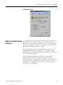
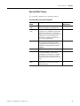
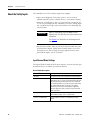
SmartGuard 600 Controller
Catalog Numbers 1752-L24BBB, 1752-L24BBBE
Safety Reference Manual
Important User Information
Solid state equipment has operational characteristics differing from those of electromechanical equipment. Safety Guidelines
for the Application, Installation and Maintenance of Solid State Controls (publication SGI-1.1 available from your local Rockwell
Automation sales office or online at http://www.rockwellautomation.com/literature/) describes some important differences
between solid state equipment and hard-wired electromechanical devices. Because of this difference, and also because of the
wide variety of uses for solid state equipment, all persons responsible for applying this equipment must satisfy themselves that
each intended application of this equipment is acceptable.
In no event will Rockwell Automation, Inc. be responsible or liable for indirect or consequential damages resulting from the use
or application of this equipment.
The examples and diagrams in this manual are included solely for illustrative purposes. Because of the many variables and
requirements associated with any particular installation, Rockwell Automation, Inc. cannot assume responsibility or liability for
actual use based on the examples and diagrams.
No patent liability is assumed by Rockwell Automation, Inc. with respect to use of information, circuits, equipment, or software
described in this manual.
Reproduction of the contents of this manual, in whole or in part, without written permission of Rockwell Automation, Inc., is
prohibited.
Throughout this manual, when necessary, we use notes to make you aware of safety considerations.
WARNING
Identifies information about practices or circumstances that can cause an explosion in a hazardous environment,
which may lead to personal injury or death, property damage, or economic loss.
IMPORTANT
Identifies information that is critical for successful application and understanding of the product.
ATTENTION
Identifies information about practices or circumstances that can lead to personal injury or death, property damage,
or economic loss. Attentions help you identify a hazard, avoid a hazard, and recognize the consequence
SHOCK HAZARD
Labels may be on or inside the equipment, for example, a drive or motor, to alert people that dangerous voltage may
be present.
BURN HAZARD
Labels may be on or inside the equipment, for example, a drive or motor, to alert people that surfaces may reach
dangerous temperatures.
Rockwell Automation, Allen-Bradley, Rockwell Automation, Rockwell Software, SmartGuard, Logix, ControlLogix, Guard I/O, POINT I/O, RSLogix 5000, RSNetWorx for DeviceNet, RSLinx, and
TechConnect are trademarks of Rockwell Automation, Inc.
Trademarks not belonging to Rockwell Automation are property of their respective companies.
Summary of Changes
The information below summarizes the changes to this manual since
the last printing.
To help you find new and updated information in this release of the
manual, we have included change bars as shown to the right of this
paragraph.
3Publication 1752-RM001D-EN-P - February 2010
Topic
Page
Updated safety data
11
Updated inputs and outputs checklist
54 and 55
3
Summary of Changes
Notes:
4
Publication 1752-RM001D-EN-P - February 2010
Table of Contents
Preface
About This Publication . . . . . . . .
Who Should Use This Publication
Understanding Terminology . . . .
Conventions . . . . . . . . . . . . . . . .
Additional Resources. . . . . . . . . .
.
.
.
.
.
.
.
.
.
.
.
.
.
.
.
.
.
.
.
.
.
.
.
.
.
.
.
.
.
.
.
.
.
.
.
.
.
.
.
.
.
.
.
.
.
.
.
.
.
.
.
.
.
.
.
.
.
.
.
.
.
.
.
.
.
.
.
.
.
.
.
.
.
.
.
.
.
.
.
.
.
.
.
.
.
.
.
.
.
.
.
.
.
.
.
.
.
.
.
.
.
.
.
.
.
7
7
7
8
8
Introduction . . . . . . . . . . . . . . . . . . .
Certification . . . . . . . . . . . . . . . . . . .
Introduction to Safety . . . . . . . . . . . .
PFD and PFH Calculated Values . . . .
Additional Safety Data . . . . . . . . . . . .
Safety Network Number . . . . . . . . . .
Configuration Signature . . . . . . . . . . .
Safety-lock with Password Protection .
Configuration and Programming . . . .
System Reaction Time . . . . . . . . . . . .
Error Diagnostics. . . . . . . . . . . . . . . .
Additional Resources. . . . . . . . . . . . .
.
.
.
.
.
.
.
.
.
.
.
.
.
.
.
.
.
.
.
.
.
.
.
.
.
.
.
.
.
.
.
.
.
.
.
.
.
.
.
.
.
.
.
.
.
.
.
.
.
.
.
.
.
.
.
.
.
.
.
.
.
.
.
.
.
.
.
.
.
.
.
.
.
.
.
.
.
.
.
.
.
.
.
.
.
.
.
.
.
.
.
.
.
.
.
.
.
.
.
.
.
.
.
.
.
.
.
.
.
.
.
.
.
.
.
.
.
.
.
.
.
.
.
.
.
.
.
.
.
.
.
.
.
.
.
.
.
.
.
.
.
.
.
.
.
.
.
.
.
.
.
.
.
.
.
.
.
.
.
.
.
.
.
.
.
.
.
.
.
.
.
.
.
.
.
.
.
.
.
.
.
.
.
.
.
.
.
.
.
.
.
.
.
.
.
.
.
.
.
.
.
.
.
.
. 9
. 9
. 9
10
11
11
12
13
14
17
17
17
Introduction . . . . . . . . . . . . . . . . . . . . . . . .
About the Controller . . . . . . . . . . . . . . . . . .
Power Supply Requirements. . . . . . . . . .
Communication Capabilities . . . . . . . . . .
Status Indication . . . . . . . . . . . . . . . . . .
Behavior for Power Supply Interruptions
Operating Mode Summary . . . . . . . . . . .
About the Safety Inputs . . . . . . . . . . . . . . . .
Input Channel Mode Settings . . . . . . . . .
Dual Channel Mode Settings. . . . . . . . . .
Error Handling. . . . . . . . . . . . . . . . . . . .
About the Safety Outputs . . . . . . . . . . . . . .
Output Channel Mode Settings . . . . . . . .
Dual Channel Mode Settings. . . . . . . . . .
Error Handling. . . . . . . . . . . . . . . . . . . .
About the Pulse Test Sources. . . . . . . . . . . .
Error Handling. . . . . . . . . . . . . . . . . . . .
Error Latch Time . . . . . . . . . . . . . . . . . . . . .
About Remote I/O . . . . . . . . . . . . . . . . . . .
Remote I/O Area Attributes . . . . . . . . . .
Status Area . . . . . . . . . . . . . . . . . . . . . .
.
.
.
.
.
.
.
.
.
.
.
.
.
.
.
.
.
.
.
.
.
.
.
.
.
.
.
.
.
.
.
.
.
.
.
.
.
.
.
.
.
.
.
.
.
.
.
.
.
.
.
.
.
.
.
.
.
.
.
.
.
.
.
.
.
.
.
.
.
.
.
.
.
.
.
.
.
.
.
.
.
.
.
.
.
.
.
.
.
.
.
.
.
.
.
.
.
.
.
.
.
.
.
.
.
.
.
.
.
.
.
.
.
.
.
.
.
.
.
.
.
.
.
.
.
.
.
.
.
.
.
.
.
.
.
.
.
.
.
.
.
.
.
.
.
.
.
.
.
.
.
.
.
.
.
.
.
.
.
.
.
.
.
.
.
.
.
.
.
.
.
.
.
.
.
.
.
.
.
.
.
.
.
.
.
.
.
.
.
.
.
.
.
.
.
.
.
.
.
.
.
.
.
.
.
.
.
.
.
.
.
.
.
.
.
.
.
.
.
.
.
.
.
.
.
.
.
.
.
.
.
.
.
.
.
.
.
.
.
.
.
.
.
.
.
.
.
.
.
.
.
.
19
19
19
20
21
22
23
24
24
25
25
26
27
27
28
29
29
29
30
30
31
Chapter 1
Safety Concept of the
SmartGuard 600 Controller
Chapter 2
Controller Overview
5Publication 1752-RM001D-EN-P - February 2010
5
Table of Contents
Chapter 3
Safety Application Development
Introduction . . . . . . . . . . . . . . . . . . . . . . . . . . .
Safety Concept Assumptions . . . . . . . . . . . . . . .
Basics of Application Development and Testing .
Establish a New Safety Network. . . . . . . . . . . . .
Specification of the Control Function . . . . . .
Configuring Devices on the Safety Network .
Programming the Application . . . . . . . . . . . .
Verify the Device Configurations . . . . . . . . .
Reset Devices . . . . . . . . . . . . . . . . . . . . . . .
Test the Application . . . . . . . . . . . . . . . . . . .
Lock All Configured Devices . . . . . . . . . . . .
Changing Your Application Program . . . . . . . . .
Edit Your Project . . . . . . . . . . . . . . . . . . . . .
.
.
.
.
.
.
.
.
.
.
.
.
.
.
.
.
.
.
.
.
.
.
.
.
.
.
.
.
.
.
.
.
.
.
.
.
.
.
.
.
.
.
.
.
.
.
.
.
.
.
.
.
.
.
.
.
.
.
.
.
.
.
.
.
.
.
.
.
.
.
.
.
.
.
.
.
.
.
.
.
.
.
.
.
.
.
.
.
.
.
.
.
.
.
.
.
.
.
.
.
.
.
.
.
.
.
.
.
.
.
.
.
.
.
.
.
.
33
33
33
34
35
36
36
36
37
37
38
39
40
Introduction . . . . . . . . . . . . . . . . . . . . . . . . . . . . . .
Assumptions . . . . . . . . . . . . . . . . . . . . . . . . . . . . . .
Operational Flow and Cycle Time . . . . . . . . . . . . . .
I/O Refresh Cycle Time and Network Reaction Time
I/O Refresh Cycle Time . . . . . . . . . . . . . . . . . . .
Network Reaction Time . . . . . . . . . . . . . . . . . . .
System Reaction Time . . . . . . . . . . . . . . . . . . . . . . .
Calculating Reaction Time . . . . . . . . . . . . . . . . .
Reaction Time Examples . . . . . . . . . . . . . . . . . .
Verifying the Reaction Time . . . . . . . . . . . . . . . .
.
.
.
.
.
.
.
.
.
.
.
.
.
.
.
.
.
.
.
.
.
.
.
.
.
.
.
.
.
.
.
.
.
.
.
.
.
.
.
.
.
.
.
.
.
.
.
.
.
.
.
.
.
.
.
.
.
.
.
.
41
41
41
43
43
44
45
45
47
51
Chapter 4
System Performance and
Reaction Time
Appendix A
Checklist for SmartGuard 600
Controllers
Overview . . . . . . . . . . . . . . . . . . . . . . . . . . . . . . . . . . . . . . 53
Index
6
Publication 1752-RM001D-EN-P - February 2010
Preface
About This Publication
This manual explains how SmartGuard 600 controllers can be used in
Safety Integrity Level (SIL) 3, according to IEC 61508, Performance
Level PL(e) according to ISO 13849-1, and Category (CAT) 4,
according to EN 954-1. It describes the SmartGuard 600-specific safety
requirements and controller features, including PFD and PFH values,
the safety network number (SNN), configuration signature,
safety-locking, and project verification.
IMPORTANT
Who Should Use This
Publication
You must read and understand the safety concepts and
requirements presented in this manual prior to operating a
SmartGuard 600 controller in a safety system.
Use this manual if you are responsible for designing, installing,
programming, or troubleshooting control systems that use
SmartGuard 600 controllers.
You must have a basic understanding of electrical circuitry and
familiarity with relay logic. You must also be trained and experienced
in the creation, operation, and maintenance of safety systems.
Understanding Terminology
The following table defines abbreviations used in this manual.
Abbreviation
Full Term
Definition
1oo2
One Out of Two
Refers to the behavioral design of a multi-processor system.
CIP
Common Industrial Protocol
A communication protocol designed for industrial automation applications.
PC
Personal Computer
Computer used to interface with a control system via programming software.
PFD
Probability of Failure on Demand
The average probability of an operational system to fail to perform its design
function on demand.
PFH
Probability of Failure per Hour
The probability of an operational system to have a dangerous failure occur per
hour.
RPI
Requested Packet Interval
When communicating over a network, this is the expected rate in time for
production of data.
SNN
Safety Network Number
A unique number that identifies a section of a safety network.
—
Standard
Any object, task, tag, program, or component in your project that is not a
safety-related item
7Publication 1752-RM001D-EN-P - February 2010
7
Preface
Conventions
The following conventions are used throughout this manual:
• Bulleted lists, such as this one, provide information, not
procedural steps.
• Numbered lists provide sequential steps or hierarchical
information.
• Bold type is used for emphasis.
Additional Resources
The table provides a listing of publications that contain important
information about SmartGuard 600 controller systems.
Resource
Description
SmartGuard 600 Controller Installation Instructions,
publication 1752-IN001
Information on installing the SmartGuard 600 controller
SmartGuard 600 Controllers User Manual, publication
1752-UM001
Information on using SmartGuard 600 controllers
DeviceNet Safety I/O Installation Instructions, publication
1791DS-IN001
Information on installing Guard I/O DeviceNet Safety
modules
Guard I/O DeviceNet Safety Modules User Manual, publication Information on using Guard I/O DeviceNet Safety
1791DS-UM001
modules
You can view or download publications at
http://literature.rockwellautomation.com. To order paper copies of
technical documents, contact your local Rockwell Automation
distributor or sales representative.
8
Publication 1752-RM001D-EN-P - February 2010
Chapter
1
Safety Concept of the SmartGuard 600
Controller
Introduction
This chapter introduces you to the safety requirements and features of
the SmartGuard 600 controller.
Topic
Certification
Page
Certification
9
Introduction to Safety
9
PFD and PFH Calculated Values
10
Additional Safety Data
11
Safety Network Number
11
Configuration Signature
12
Safety-lock with Password Protection
13
Configuration and Programming
14
System Reaction Time
17
Error Diagnostics
17
Additional Resources
17
Certificate No. 968/EZ238.00/06
TÜV Rheinland Group
TÜV Industrie Service GmbH
Automation, Software, and Informationstechnologie
Safety restrictions can be found in this manual.
For a listing of TÜV-certified product and software versions, refer to:
http://www.rockwellautomation.com/products/certification/safety/index.html.
Introduction to Safety
9Publication 1752-RM001D-EN-P - February 2010
The SmartGuard 600 controller is type-approved and certified for use
in safety applications up to and including Safety Integrity Level (SIL) 3,
according to IEC 61508, Performance Level PL(e) according to
ISO 13849-1, and Category (CAT) 4, according to EN954-1.
SIL requirements are based on the standards current at the time of
certification.
9
Chapter 1
Safety Concept of the SmartGuard 600 Controller
The TÜV Rheinland Group has approved the SmartGuard 600
controller for use in safety applications in which the de-energized
state is considered to be the safety state.
Hardware modules and software components that are not fail-safe, but
do not cause any adverse reactions, can be used to process standard
signals. However, they cannot be used to carry out safety tasks.
ATTENTION
IMPORTANT
Limit the use of standard devices in your application to
standard critical components. If you choose to use standard
devices in a safety critical fashion, you must be sure that the
system design meets SIL 3 requirements.
You are responsible for:
• the set-up, SIL rating, and validation of any sensors or
actuators connected to the system.
• project management and functional testing.
• access control to the safety system, including password
handling. When applying Functional Safety, restrict access
to qualified, authorized personnel who are trained and
experienced.
• programming the application software and the device
configurations in accordance with the information in this
safety reference manual and the SmartGuard 600
Controllers User Manual, publication 1752-UM001.
PFD and PFH Calculated
Values
IEC 61508 requires you to perform various functional verification
(proof) tests of the equipment used in the system. The controller
should be included in the functional-verification testing of the other
components in the safety system.
The average probability of a system to fail to satisfactorily perform its
safety function on demand is called probability of failure on demand
(PFD). The probability of a system to have a dangerous failure occur
per hour is called probability of failure per hour (PFH).
10
Publication 1752-RM001D-EN-P - February 2010
Safety Concept of the SmartGuard 600 Controller
Chapter 1
PFD and PFH calculations have been carried out for the SmartGuard
600 controller in accordance with IEC 61508. These values must be
calculated for the overall devices within the system to comply with the
SIL required for the specific application.
PFD and PFH Calculations for SmartGuard 600 Controllers
Additional Safety Data
Functional Verification Test Interval (Years)
PFD
PFH
0.25
4.30E-07
3.93E-10
8.56E-07
3.91E-10
1
1.71E-06
3.90E-10
2
3.41E-06
3.89E-10
5
8.53E-06
3.89E-10
10
1.71E-05
3.89E-10
20
3.418E-05
3.889E-10
These additional pieces of data are used in SIL calculations for the
SmartGuard 600 controllers:
•
•
•
•
Safety Network Number
0.5
Safe failure fraction - 99.94%
Diagnostic coverage - greater than 90%
Mean Time to Failure (MTTFd) = over 100 years
Total Common Cause Failure (CCF) = over 65
The safety network number (SNN) is a unique number that identifies
the safety network sub-net. The SNN, in conjunction with the target’s
node address, enables a target to determine with high integrity
whether or not safety connection requests it receives have reached the
correct destination.
Each end node in a DeviceNet Safety control system must have a
unique node identifier. This unique node reference for a DeviceNet
Safety node is a combination of the SNN and the node address of the
network device. It is used to precisely identify the intended target
device during configuration and I/O connection establishment.
Any device that originates a safety connection to another safety device
must be configured with the SNN of the target device.
The configuration software automatically assigns an SNN, based on
the date and time, when a new network configuration file is created.
Publication 1752-RM001D-EN-P - February 2010
11
Chapter 1
Safety Concept of the SmartGuard 600 Controller
For typical users, the automatic assignment of an SNN is sufficient.
However, you can assign an SNN manually.
IMPORTANT
IMPORTANT
If you assign an SNN manually, take care to ensure that system
expansion does not result in duplication of SNN and node
address combinations.
If you are using a device that has been used in another location,
reset the device to the out-of-box configuration by right-clicking
the device and choosing Reset Safety Device. Check the Safety
Network Number checkbox and click OK.
Refer to the SmartGuard 600 Controllers User Manual,
publication 1752-UM001, for more information on safety reset.
ATTENTION
Configuration Signature
If a safety project is copied to another project intended for a
different hardware installation and that installation may reside
within the same routable safety system, the SNN must be
changed to be sure that the SNN is not repeated.
The configuration signature defines the controller’s configuration. It
can be read and monitored and is used to uniquely identify the
controller’s configuration in several operations.
• During download from the configuration software, the
configuration signature provides you with a means to check that
the device and the configuration tool agree on the information
downloaded.
• During device replacement, the configuration signature lets you
verify that the configuration in the software is the correct
configuration. If the originator is used to automatically configure
a device, the configuration signature indicates whether
reconfiguration is necessary and ensures the integrity of the
operation.
• During connection establishment, the originator and the target
devices use the configuration signature to ensure that both
devices agree on the device configuration.
• The configuration signature is auto-generated by the
configuration software when a SmartGuard 600 controller is
added to the project.
12
Publication 1752-RM001D-EN-P - February 2010
Safety Concept of the SmartGuard 600 Controller
Chapter 1
Configuration Signature
Safety-lock with Password
Protection
The configuration of the controller can be protected by the use of an
optional password. Download, safety-reset, and safety-lock and
-unlock are password protected. When a device is safety-locked, you
also cannot change the password or change the status of the device,
without first entering the existing password.
After configuration data has been downloaded and verified, the
configuration data within the controller can be protected using
RSNetWorx for DeviceNet software. Run the Safety Device Verification
Wizard to lock the controller.
When applying Functional Safety, restrict access to qualified,
authorized personnel who are trained and experienced. The
safety-lock function with passwords is provided by the Safety Device
Verification Wizard in RSNetWorx for DeviceNet software. You are
responsible for controlling access to the safety system, including
password use and handling.
Publication 1752-RM001D-EN-P - February 2010
13
Chapter 1
Safety Concept of the SmartGuard 600 Controller
Verification Wizard
If you forget a password, you can reset passwords using the vendor
password. Contact Rockwell Automation Technical Support and
provide the device’s serial number and security code to obtain the
vendor password.
Configuration and
Programming
Use RSNetWorx for DeviceNet software, version 8.0 (minimum) or
later (version 9.1 is recommended), to configure, program, and
monitor the status of the 1752-L24BBB controller. Use RSNetWorx for
DeviceNet software, version 9.1 or later, to configure, program, and
monitor the status of the 1752-L24BBBE controller. With RSNetWorx
for DeviceNet software, you can configure the controller by using the
SmartGuard controller’s USB port or via the DeviceNet network or
EtherNet/IP network. The logic editor is launched from within
RSNetWorx for DeviceNet software.
You also need RSLinx software, version 2.55 or later, which lets you
configure a 1752-L24BBBE controller on an EtherNet/IP network.
A variety of SIL 3-compliant applications can be programmed using
the logic functions and function blocks supported by the controller. A
maximum of 254 logic functions and function blocks can be used in a
maximum of 32 programming pages. You can password-protect both
configuration data and project files.
14
Publication 1752-RM001D-EN-P - February 2010
Safety Concept of the SmartGuard 600 Controller
Chapter 1
The controller supports these logic functions:
•
•
•
•
•
•
•
•
•
NOT
AND
OR
Exclusive OR
Exclusive NOR
Routing
RS flip-flop
Multi-connector
Comparator
The controller supports these function blocks:
•
•
•
•
•
•
•
•
•
•
•
•
•
•
Reset
Restart
Emergency stop push button monitoring
Light curtain monitoring
Safety gate monitoring
Two-hand controller
OFF-delay timer
ON-delay timer
User mode switch
External device monitoring
Muting
Enable switch
Pulse generator
Counter
Programs are created from logic functions and function blocks that
indicate commands, from input tags that indicate data input sources,
and from output tags that indicate data output destinations.
Publication 1752-RM001D-EN-P - February 2010
15
Chapter 1
Safety Concept of the SmartGuard 600 Controller
Input tags reflect the status of inputs from these I/O areas:
•
•
•
•
•
•
•
•
•
Input area of the controller’s local terminals
Input area of safety slaves registered as communication partners
I/O area reflected from safety master data
I/O area reflected from standard master data
Local input status
Local output status
General unit status
Test output status
Muting lamp status
Output tags reflect the status of outputs from these I/O areas:
• Output area of the controller’s local terminals
• Output area of safety slaves registered as communication
partners
• I/O area reflected from safety master data
• I/O area reflected from standard master data
ATTENTION
Always verify that safety-related signals used in safety-related
logic meet applicable standards and regulations. Use only
safety input signals to function blocks. It is your responsibility
to verify that the proper sources for signals used in conjunction
with these function blocks and the overall safety logic
implementation adhere to relevant safety standards and
regulations.
Only safety data transmitted over safety connections may be
used as safety data in safety application logic.
Permitted Use of Safety and Standard Data
End-device Signal Definition
Safety
Standard
16
Connection Type
Permitted Use in Application
Safety
Safety
Standard
Standard
Safety
Standard
Standard
Standard
Publication 1752-RM001D-EN-P - February 2010
Safety Concept of the SmartGuard 600 Controller
System Reaction Time
Chapter 1
The system reaction time is the amount of time from a safety-related
event as input to the system until the system is in the safe state. The
system reaction time is the sum of the reaction times of each element
in the safety chain, considering the occurrence of faults or errors in
that safety chain. The system reaction time must meet the required
safety system specifications.
See Chapter 4 for examples of typical safety chains and system
reaction time calculations.
Error Diagnostics
Status indicators and an alphanumeric display provide status and error
information about the SmartGuard 600 controller. You can also view
status and error messages in the error log using RSNetWorx for
DeviceNet software.
Controller errors fall into three categories: nonfatal errors, abort errors,
and critical errors.
Controller Error Categories
Additional Resources
Error Type
Controller Response
Nonfatal
When a nonfatal error occurs, the controller places the local I/O
terminal or safety I/O connection where the error occurred into
the safety state. The controller continues to operate in Run mode.
Abort
When an abort error occurs, the controller completely stops safety
functions and places them in the safety state. To enable you to
check the error state, explicit message communication is
supported.
Critical
When a critical error occurs, all controller functions stop. The
error log is saved in nonvolatile memory.
Refer to the SmartGuard 600 Controllers User Manual, publication
1752-UM001, for more information on the following:
• Programming and details on logic functions and function block
operation
• Controller error handling and error log descriptions
• Safety reset
Chapter 2 of this manual also contains information on I/O error
handling.
Publication 1752-RM001D-EN-P - February 2010
17
Chapter 1
Safety Concept of the SmartGuard 600 Controller
Notes:
18
Publication 1752-RM001D-EN-P - February 2010
Chapter
2
Controller Overview
Introduction
Topic
About the Controller
Page
About the Controller
19
About the Safety Inputs
24
About the Safety Outputs
26
About the Pulse Test Sources
29
Error Latch Time
29
About Remote I/O
30
The SmartGuard 600 controller (catalog numbers 1752-L24BBB and
1752-L24BBBE) are programmable electronic systems featuring 16
digital inputs, 8 digital outputs, 4 test pulse sources, and connections
for USB and DeviceNet safety communication. In addition, the
1752-L24BBBE controller offers EtherNet/IP connectivity.
IMPORTANT
The SmartGuard controllers must not be directly connected to
any network that is not protected from outside intrusion. For
example, do not connect the SmartGuard 600 controller to an
Ethernet network that is not protected with a firewall or other
security measures.
Power Supply Requirements
Power for the controller is provided via an external 24V DC power
source. The output hold time must be 20 ms or longer.
To comply with the CE Low Voltage Directive (LVD), DeviceNet
connections and I/O must be powered by a DC source compliant with
safety extra low voltage (SELV) or protected extra low voltage (PELV).
To comply with UL restrictions, DeviceNet connections and I/O must
be powered by DC sources whose secondary circuits are isolated from
the primary circuit by double insulation or reinforced insulation. The
DC power supply must satisfy the requirements for Class 2 circuits or
limited voltage/current circuits defined in UL 508.
19Publication 1752-RM001D-EN-P - February 2010
19
Chapter 2
Controller Overview
Communication Capabilities
The controller can act as a DeviceNet safety master or slave, as a
DeviceNet standard slave, EtherNet/IP standard target, or as a
standalone controller when DeviceNet communication is disabled.
Explicit messages can be used to read controller status information.
Explicit messages configured from the RSNetWorx for DeviceNet
software can be sent from the user program. The messages can be
routed between DeviceNet and EtherNet/IP networks.
The USB port can be used to program the SmartGuard controller and
to configure devices on the DeviceNet network. The SmartGuard
provides some limited pass-through capability from USB to DeviceNet,
for programming and configuration purposes. When used in
Standalone mode, the controller communicates with the configuration
software via USB communication.
IMPORTANT
The data attributes handled by standard I/O communication and
explicit message communication are non-safety data. The
necessary measures for safety data are not taken during
generation of standard or explicit message data. Do not use
this data to operate a safety control system.
A single controller can function simultaneously as a DeviceNet safety
master, DeviceNet safety slave, DeviceNet standard slave, and an
EtherNet/IP standard target.
DeviceNet Safety Master
As a safety master, the controller can perform safety I/O
communication with up to 32 connections, using up to 16 bytes per
connection. A master-slave relationship is established for each
connection on the DeviceNet Safety network, separate from the
master-slave communication on the DeviceNet standard network. This
enables the controller to be the safety master to control the
connections.
20
Publication 1752-RM001D-EN-P - February 2010
Controller Overview
Chapter 2
DeviceNet Safety Slave
As a safety slave, the controller can perform safety I/O communication
with a maximum of four connections, using up to 16 bytes per
connection. The controller’s internal status information and a specified
area of I/O can be allocated in the safety master.
DeviceNet Standard Slave or EtherNet/IP Standard Target
As a standard slave, the controller can perform standard I/O
communication on DeviceNet or EtherNet/IP networks with one
standard master for up to two connections, using up to 16 bytes per
connection (128 bytes for input data for EtherNet/IP communication).
The controller’s internal status information and a specified area of I/O
can be allocated in the standard master.
Status Indication
The controller’s internal status information and I/O data can be
monitored online using RSNetWorx for DeviceNet software with either
a USB or DeviceNet network connection or EtherNet/IP connection.
The status indicators and alphanumeric display on the controller
provide status and error information.
IMPORTANT
Status indicators are not reliable indicators for safety functions.
They should be used only for general diagnostics during
commissioning or troubleshooting. Do not attempt to use status
indicators as operational indicators.
When the service switch on the front of the controller is pressed, the
alphanumeric display shows the controller’s safety configuration
signature two digits at a time for a total of ten pairs of numbers.
Errors detected by the controller are recorded in an error history log,
along with the total operating time (starting when the controller
entered the Execute mode) at the time the error was detected.
Publication 1752-RM001D-EN-P - February 2010
21
Chapter 2
Controller Overview
Behavior for Power Supply Interruptions
The controller reacts when voltage drops to 85% of the rated voltage
or lower, but can recover if the power supply voltage returns to 85%
or more of the rated voltage.
Voltage Drops
If the power supply voltage for the internal circuit (V0, G0) drops to
85% of the rated voltage or lower, the controller turns off the outputs.
If the power supply voltage for inputs (V1, G1) drops to 85% of the
rated voltage or lower when the power supply for the internal circuit
is normal, the controller continues operating, but will not refresh
inputs. Similarly, if the power supply, voltage for outputs (V2, G2)
drops to 85% of the rated voltage or lower, the controller will
continue operation but will stop refreshing outputs.
Automatic Recovery
If the power supply returns to 85% of the rated voltage or more
because of a fluctuation in the power supply voltage:
• operation might automatically restart. This occurs if the power
supply to the controller is completely stopped because of a
voltage drop to 85% of the rated voltage or lower.
• a critical error could occur, which will require you to cycle the
power supply to restore operation. This occurs if the power
supply fluctuates around the lower operational limit of the
internal power/voltage detection circuit.
I/O refresh is automatically restarted when the power supply is
recovered to 85% or more of the rated voltage. The I/O power
monitor error is also automatically cancelled.
22
Publication 1752-RM001D-EN-P - February 2010
Controller Overview
Chapter 2
Operating Mode Summary
The controller supports these operating modes.
SmartGuard 600 Controller Operating Modes
Publication 1752-RM001D-EN-P - February 2010
Operating
Mode
Description
Module Status
(MS) Indicator
Self-diagnostic
mode
The controller performs internal self-diagnosis
to ensure the integrity of safety functions.
Flashing red/green
Configuration
mode
While waiting for the completion of
configuration from RSNetWorx for DeviceNet
software, the controller is in Configuration
mode. The controller switches to Configuration
mode when it is not yet configured after
initialization is complete or when there is an
error in the configuration data.
Flashing red/green
Idle mode
The controller enters Idle mode while waiting
for Run mode after initialization has been
completed. Non-safety-related control, such as
standard I/O and message communication, is
supported.
Flashing Green
Run mode
Safety and non-safety control are supported.
Solid green
Abort mode
The controller changes to Abort mode if the
controller node address switch setting is
changed after the configuration is complete.
The controller stops all functions except for
message communication and enters the safety
state.
Flashing red
Critical Error
mode
The controller enters this mode and sends all
safety functions to the safety state when a
critical error occurs.
Solid red
23
Chapter 2
Controller Overview
About the Safety Inputs
The controller has 16 local safety inputs that support:
• input circuit diagnosis. Test pulse sources can be used to
monitor internal circuits, external devices, and external wiring.
• input on- and off-delays. You can set input time constraints of
0...126 ms in multiples of the controller cycle time. Setting input
on- and off-delays helps reduce the influence of chattering and
external noise.
IMPORTANT
Input on- and off-delays must be added to the I/O
response time. This will affect the system reaction time
calculations.
See Chapter 4 for information on calculating reaction
times.
• Dual Channel mode. You can set Dual Channel mode for pairs
of related local inputs. When Dual Channel mode is set, time
discrepancies in data changes or input signals between two
paired local inputs can be evaluated.
Input Channel Mode Settings
The Input Channel mode of local safety inputs is set based on the type
of external device to which you want to connect.
Channel Mode Descriptions
24
Channel Mode
Description
Not used
The input channel is not connected to an external device.
Test pulse from test output
Use this mode when connecting a contact-type safety
input device (such as E-stop or Gate Interlock) to the input
that will perform pulse testing on the circuit. Select the
test output terminal to use as the test source and set the
test output mode to Pulse Test Output. This enables
detection of short circuits with the power supply line
(positive side), earth faults, and short circuits with other
input signal lines.
Used as a safety input
Use this mode to connect to a safety device with a
semiconductor output, such as a light curtain.
Used as a standard input
Use this mode to connect to a standard (non-safety)
device.
Publication 1752-RM001D-EN-P - February 2010
Controller Overview
Chapter 2
Dual Channel Mode Settings
Local safety input channels can be set to Dual Channel mode. Setting
Dual Channel mode enables the status of two inputs to be evaluated
and reflected in I/O tags. The discrepancy time between changes in
the status of two inputs can also be evaluated.
Dual Channel Mode Input Settings
Channel Mode
Description
Single Channel
The safety input terminal is used independently.
Dual Channel Equivalent
The safety input terminal is used as a Dual Channel
Equivalent with a pair safety input terminal.
Dual Channel Complementary
The safety input terminal is used as a Dual Channel
Complement with a paired safety input terminal.
The controller supports function blocks with diagnostic functionality
equivalent to Dual Channel mode. In many case, annunciation and
troubleshooting of system faults is easier when the function blocks are
used to detect faults rather than the SmartGuard hardware. If you wish
to use the function blocks to detect system faults, the safety inputs
must be configured for single channel.
Error Handling
When an error is detected, the reaction of the controller depends
upon the channel mode setting: Single or Dual Channel.
In Single Channel mode, if an error is detected during self-diagnosis:
• I/O tags that correspond to the safety input terminals with errors
are made inactive.
• the status indicator for the safety input terminals with errors
illuminates red.
• the error is written in the error history.
• the controller continues to operate.
If a discrepancy error is detected in Dual Channel mode:
• I/O tags that correspond to the safety input pairs with errors are
made inactive.
• status indicators for both input pairs illuminate red.
• the errors are written in the error history.
• the controller continues to operate.
Publication 1752-RM001D-EN-P - February 2010
25
Chapter 2
Controller Overview
If an error is detected in one of the two inputs in Dual Channel mode:
• I/O tags that correspond to the safety input pairs with errors are
made inactive.
• the status indicator of the safety input with the error illuminates
red. The status indicator of the paired input flashes red.
• the error appears in the error history.
• the controller continues to operate.
To recover from an error in a safety input:
• the cause of the error must be removed.
• the error latch time must have passed.
• the input signal must return to inactive status with no error
condition detected, for example, by pressing an emergency stop
button or opening a door.
About the Safety Outputs
The controller has eight local safety outputs that support:
• output circuit diagnosis. Test pulses can be used to diagnose the
controller’s internal circuits, external devices, and external
wiring.
• overcurrent detection and protection. To protect the circuit, an
output is blocked when an overcurrent is detected.
• Dual Channel mode. Both of two paired outputs can be set into
a safety state when an error occurs in either of the two paired
local outputs without depending on the user program.
26
Publication 1752-RM001D-EN-P - February 2010
Controller Overview
Chapter 2
Output Channel Mode Settings
You set the Output Channel mode based on the type of external
device to which you want to connect.
Output Channel Mode Descriptions
Channel Mode
Description
Not used
The output terminal is not connected to an output device.
Safety
A test pulse is not output when the output is on. When
the output is off, short circuits with the power supply line
can be detected. Ground faults can also be detected.
Safety Pulse Output
A test pulse is output when the output is on. This enables
detection of short circuits with the power supply line
(positive side) whether the output is on or off. Ground
faults and short circuits between output signals can also
be detected.
IMPORTANT
If a safety pulse output is set, an off pulse signal (pulse width
580 μs) is output to diagnose the output circuit when the safety
output turns on. Check the input response time of the control
device to make sure this output pulse will not cause
malfunctions.
Dual Channel Mode Settings
Local safety output terminals can also be set to Dual Channel mode.
Setting Dual Channel mode enables an error to be detected if the two
outputs from a user program are not equivalent. If an error is detected
in one of two outputs circuits, both outputs to the device will become
inactive.
Dual Channel Mode Output Settings
Publication 1752-RM001D-EN-P - February 2010
Channel Mode
Description
Single Channel
The safety output terminal is used independently.
Dual Channel
The safety output terminal is paired with another output terminal.
The output can be turned on when both the output and the paired
safety output are set to the same state.
27
Chapter 2
Controller Overview
Error Handling
When an error is detected, the reaction of the controller depends
upon the channel mode setting: Single or Dual Channel.
If an error is detected in Single Channel mode during self-diagnosis:
• the safety output with the error becomes inactive without
depending on the user program.
• the status indicator of the safety output with the error illuminates
red.
• the error is written in the error history.
• the controller continues to operate.
If an error is detected in one of the two paired outputs in Dual
Channel mode:
• both outputs become inactive without depending on the user
program.
• the status indicator of the output with the error illuminates red.
The status indicator of the paired output flashes red.
• the error is written in the error history.
• the controller continues to operate.
If the two outputs from the user program to the output I/O tags are
not equivalent:
• both outputs to the external device become inactive without
depending on the user program.
• the status indicators for the paired outputs illuminate red.
• the error is written in the error history.
• the controller continues to operate.
To recover from an error in a safety output:
• the cause of the error must be removed.
• the error latch time must have passed.
• the output signals to the output I/O tags from the application
that correspond to the safety output terminals must go inactive.
IMPORTANT
28
If Dual Channel mode is set for two outputs to implement
redundant circuits and an error is detected for one of the two
outputs, the other output can be forced to go inactive without
relying on the user program. If the redundant circuits are
implemented using two outputs in Single Channel mode, user
program logic must be written to detect the error, using the
External Device Monitoring function block.
Publication 1752-RM001D-EN-P - February 2010
Controller Overview
About the Pulse Test
Sources
Chapter 2
These four independent test outputs are normally used in combination
with safety inputs. They can also be set for use as signal (standard)
output terminals. The test pulse outputs feature:
• current monitoring for muting lamp. A disconnect can be
detected for the T3 terminal only.
• overcurrent detection and protection. To protect the circuit, an
output is blocked when an overcurrent is detected.
ATTENTION
Pulse test outputs must not be used as safety-related outputs
(for example, for the control of safety-related actuators).
Error Handling
The controller performs the following operations if an error is
detected during self-diagnosis:
• The output terminals for which errors have been detected are
made inactive without intervention from the user program.
• The error is written in the error history.
• The controller continues to operate.
Error Latch Time
You can set the time to latch the error state when an error occurs in a
safety input terminal, safety output terminal, or test output terminal.
The error state continues until the error latch time passes even if the
cause of the error is momentarily removed. When monitoring errors
from a monitoring system, take the monitoring interval into account
when setting the error latch time.
The error latch time can be set from 0…65,530 ms in increments of
10 ms. The default setting is 1000 ms.
IMPORTANT
Publication 1752-RM001D-EN-P - February 2010
Errors detected at test output terminals are automatically reset
after the error latch time. Leaving the short-circuit state as is
may result in failure due to increased temperatures. If an
external load short-circuit occurs, remove the cause
immediately.
29
Chapter 2
Controller Overview
About Remote I/O
The remote I/O areas used in safety masters or slaves and standard
masters or slaves are automatically allocated in the controller’s I/O
memory, according to settings made in RSNetWorx for DeviceNet
software.
Remote I/O Area Attributes
The controller’s remote I/O area has mode change, communication
error, and power on attributes. All values in the safety remote I/O area
are cleared if the operating mode is changed. If a communication
error occurs, all data for the connection with the error is cleared.
Remote I/O Area Attributes
Remote I/O Area Type
Mode Change
Communication Error
Power On
Run to Idle
Run or Idle to Configuration
DeviceNet safety remote
I/O area
Cleared (safety state)
Cleared (safety state)
Cleared for the connection Cleared
(safety state)
(safety state)
DeviceNet standard
remote I/O area
Depends upon slave I/O
area hold setting
Cleared
Depends upon slave I/O
area hold setting
Cleared
The standard slave I/O area hold setting specifies whether to clear or
hold the data in the standard slave I/O area when the operating mode
is changed or when a communication error occurs. The default setting
is clear. Both settings are valid when power is cycled.
Slave I/O Area Hold Settings
Setting
Description
Clear
The standard slave output area (inputs to the SmartGuard application
program) is cleared when a communication (connection) error occurs.
The standard slave input area (outputs to a standard master) is cleared when
the operating mode is changed to Idle.
Hold
The last data in the standard slave output area (inputs to the SmartGuard
application program) is held when a communication (connection) error
occurs.
The last data in the standard slave input area (outputs to a standard master)
is held when the operating mode is changed to Idle.
Values are cleared when a critical error or abort occurs or when the power
supply is turned on again.
30
Publication 1752-RM001D-EN-P - February 2010
Controller Overview
Chapter 2
Status Area
When the controller operates as an input safety slave or a standard
slave, status information can be added to the first line of the transmit
data. This information can be stored in a programmable controller and
used to establish a monitoring system.
Status Information
Tag Name
Data Size
Attribute Type
General Status
Byte
Non-safety
Local Input Status
Word
Safety
Local Output Status
Byte
Safety
Test Output/Muting Lamp Status
Byte
Non-safety
ATTENTION
For data with a non-safety attribute, the necessary measures
for safety data are not taken during data generation. Do not use
this data to operate a safety control system.
In addition, even if the attribute for an item is safety, it
becomes non-safety if data is input using standard
communication or I/O tags connected with standard devices.
Therefore, those items must not be used to operate a safety
control system.
Publication 1752-RM001D-EN-P - February 2010
31
Chapter 2
Controller Overview
Notes:
32
Publication 1752-RM001D-EN-P - February 2010
Chapter
3
Safety Application Development
Introduction
Topic
Page
Safety Concept Assumptions
33
Basics of Application Development and Testing
33
Establish a New Safety Network
34
Changing Your Application Program
39
Safety Concept
Assumptions
The safety concept assumes that:
Basics of Application
Development and Testing
The application program for the intended SIL 3 system should be
developed by the system integrator and/or user trained and
experienced in safety applications. The developer must follow good
design practices.
• those responsible for creating, operating, and maintaining the
application are fully qualified, specially trained personnel,
experienced in safety systems.
• you apply the logic correctly, meaning that programming errors
can be detected. Programming errors can be detected by strict
adherence to specifications, programming, and naming rules.
• you perform a critical analysis of your application and use all
possible measures to detect a failure.
• you confirm all application downloads via a manual check of
the configuration signatures.
• you perform a complete functional test of the entire system
before the initial startup of a safety-related system.
• Use functional specifications, including:
– flow charts.
– timing diagrams.
– sequence charts.
• Perform a program review.
• Perform program validation.
33Publication 1752-RM001D-EN-P - February 2010
33
Chapter 3
Safety Application Development
Establish a New Safety
Network
The flowchart below shows the steps required for commissioning a
new SmartGuard 600 controller system. Items in bold are explained in
the following sections.
Specify the Control Function
Configure Devices on the Network
Program the Application
Calculate Maximum Reaction Time
Reconfigure Devices
Save the Network Configuration File
Connect to the Network and Download
Verify the Device Configurations
No
Configurations
Match?
Reset Devices
Yes
Test the Application
Correct the Application
Logic
No
Tests Passed?
Yes
Lock All Configured Devices
Save the Network Configuration File
and Run the Application
For information on calculating response time, see Chapter 4.
34
Publication 1752-RM001D-EN-P - February 2010
Safety Application Development
Chapter 3
Specification of the Control Function
You must create a specification for your control function. Use this
specification to verify that program logic correctly and fully address
your application’s functional and safety control requirements. The
specification may be presented in a variety of formats, depending on
your application. However, the specification must be a detailed
description that includes the following (if applicable):
•
•
•
•
•
•
Sequence of operations
Flow and timing diagrams
Sequence charts
Program description
Program print out
Verbal descriptions of the steps with step conditions and
actuators to be controlled, including:
– input definitions.
– output definitions.
– I/O wiring diagrams and references.
– theory of operation.
• Matrix or table of stepped conditions and the actuators to be
controlled, including the sequence and timing diagrams
• Definition of marginal conditions, for example, operating modes
or emergency stop
The I/O portion of the specification must contain the analysis of field
circuits, that is, the type of sensors and actuators.
• Sensors (Digital or Analog)
– Signal in standard operation (dormant current principle for
digital sensors, sensors OFF means no signal)
– Determination of redundancies required for SIL levels
– Discrepancy monitoring and visualization, including your
diagnostic logic
• Actuators
– Position and activation in standard operation (normally OFF)
– Safe reaction/positioning when switching OFF or power
failure
– Discrepancy monitoring and visualization, including your
diagnostic logic
Publication 1752-RM001D-EN-P - February 2010
35
Chapter 3
Safety Application Development
Configuring Devices on the Safety Network
You must commission all devices with the node address, safety
network number (SNN), and communication rate, if necessary, before
their installation on the safety network. Devices are assigned an SNN
and configured using RSNetWorx for DeviceNet software, version 8 or
later.
IMPORTANT
Perform user testing to make sure the system bandwidth does
not cause problems.
Programming the Application
The logic and instructions used in programming the application must
be:
•
•
•
•
easy
easy
easy
easy
to
to
to
to
understand.
trace.
change.
test.
All logic should be reviewed and tested. Keep safety-related logic and
non-safety-related logic separate.
Labeling the Program
The application program is clearly identified by one of the following:
•
•
•
•
Name
Date
Revision
Any other user identification
Verify the Device Configurations
Because RSNetWorx for DeviceNet software is not a SIL 3-certified
application, the configuration values resulting from user operations
and software computation are not considered to be of high integrity
until download, read-back, and user testing is complete.
36
Publication 1752-RM001D-EN-P - February 2010
Safety Application Development
Chapter 3
After the configuration is downloaded to the devices, perform these
steps to verify the device configurations.
1. Read the configuration back from the device and print it out.
2. Compare this printed configuration to the configuration from
RSNetWorx for DeviceNet software.
3. Check that the printed configuration meets the application
specification requirements.
4. Reset and reconfigure the affected devices if the configurations
do not match, or the application requirements are not met.
IMPORTANT
You must review all safety device configurations and record the
configuration signatures prior to operating a safety application.
Reset Devices
When changing a configuration because of verification or user testing
results, you must clear the previous configuration before downloading
the new parameters. Reset the device by setting the reset type to
Return to out-of-box configuration and emulate cycling power.
Refer to the SmartGuard 600 Controller User Manual, publication
1752-UM001, for details.
Test the Application
To check the application program for adherence to the specification,
you must generate a suitable set of test cases covering the application.
The set of test cases must be filed and retained as the test
specification.
You must include a set of tests to prove the validity of the calculations
(formulas) used in your application logic. Equivalent range tests are
acceptable. These are tests within the defined value ranges, at the
limits, or in invalid value ranges. The necessary number of test cases
depends on the formulas used and must comprise critical value pairs.
Active simulation with sources (field devices) must also be included,
since it is the only way to verify that the sensors and actuators in the
system are wired correctly. Verify the operation of programmed
functions by manually manipulating sensors and actuators.
Publication 1752-RM001D-EN-P - February 2010
37
Chapter 3
Safety Application Development
You must also include tests to verify the reaction to wiring faults and
network communication faults.
This includes required functional verification tests of fault routines,
input and output channels to make sure that the safety system
operates properly.
To perform a functional verification test on the controller, you must
perform a full test of the application. You must toggle each sensor and
actuator involved in every safety function. From a controller
perspective, this means toggling the I/O point going into the
controller, not necessarily the actual actuators. Be sure to test all
shutdown functions, since these functions are typically not exercised
during normal operation.
Also, be aware that a functional verification test is only valid for the
specific application tested. If the controller is moved to another
application, you must also perform start-up and functional verification
testing on the controller in the context of the new application.
An independent, third-party review of the safety system may be
required before the system is approved for operation.
Lock All Configured Devices
IMPORTANT
Before you lock your safety device configurations, you must
perform all of the verification steps required for your
application.
Lock the configuration of all devices to indicate they have been
verified, as well as to prevent parameters from being unintentionally
modified.
Run the Safety Device Verification Wizard in RSNetWorx for DeviceNet
software to safety-lock your devices.
38
Publication 1752-RM001D-EN-P - February 2010
Safety Application Development
Changing Your Application
Program
Publication 1752-RM001D-EN-P - February 2010
Chapter 3
The following rules apply to changing your application program:
• Only authorized, specially-trained personnel can make program
edits. These personnel should use all supervisory methods
available, for example, using the software password protections.
• When authorized, specially-trained personnel make program
edits, they assume the central safety responsibility while the
changes are in progress. These personnel must also maintain
safe application operation.
• You must sufficiently document all program edits, including:
– authorization.
– impact analysis.
– execution.
– test information.
– revision information.
• Before you connect a device to the network, you must clear the
previous configuration.
• You must commission all devices with the node address, safety
network number (SNN), and communication rate, if necessary,
before their installation on the safety network.
39
Chapter 3
Safety Application Development
Edit Your Project
This flowchart explains the steps required to modify an existing
network and user program.
Specify the Control Function
Connect to the Network and Upload the
Existing Configuration
Unlock Device Configurations
Reset Devices
Change the network, change device
parameters, or edit the application
program according to the specified
changes.
Calculate Maximum Reaction Time
Save the Network Configuration File
Reconfigure Devices
Connect to the Network and Download
Verify the Device Configurations
Configurations
Match?
No
Reset Devices
Yes
Test the Application
Correct the Application
Logic
Tests Passed?
No
Yes
Lock All Configured Devices
Save the Network Configuration File
and Run the Application
40
Publication 1752-RM001D-EN-P - February 2010
Chapter
4
System Performance and Reaction Time
Introduction
Topic
Assumptions
Page
Assumptions
41
Operational Flow and Cycle Time
41
I/O Refresh Cycle Time and Network Reaction Time
43
System Reaction Time
45
The calculations shown here assume that:
• the configuration is correct.
• the power has been turned on, the self-diagnostic function has
completed, and the controller is in Run mode.
• the necessary safety slaves have been added to the system.
Operational Flow and Cycle
Time
The operation of the controller is outlined in the flow diagram. The
controller initializes itself internally when the power is turned on.
Unless there are errors, the controller cyclically executes system
processing, such as DeviceNet, EtherNet/IP, and USB communication,
I/O refresh, and user program logic. In Standalone Controller mode,
the controller executes all but the DeviceNet and EtherNet/IP
communication processes. The cycle time depends on the scale of the
user program and the configuration of DeviceNet remote I/O
communication.
IMPORTANT
41Publication 1752-RM001D-EN-P - February 2010
Approximately six seconds are required to complete
initialization after the power is turned on. Initialization
processing includes the self-diagnosis required for the
controller to perform safety functions.
41
Chapter 4
System Performance and Reaction Time
Operational Flow
Power On
Initialize
System Processing
Communication Processing
Cycle Time
I/O Refresh
User Application Calculation
Cycle time is expressed by the following formula:
Controller cycle time =
System processing time + DeviceNet and/or USB communication time
+ I/O refresh time + User application execution time
The cycle time of the controller is set in 1 ms increments, depending
upon the configuration. You can view the cycle time in RSNetWorx for
DeviceNet software.
Mode/Cycle Tab in RSNetWorx for DeviceNet Software
42
Publication 1752-RM001D-EN-P - February 2010
System Performance and Reaction Time
Chapter 4
After the controller has started operating, DeviceNet connections are
established and devices are verified to start DeviceNet safety I/O
communication. This process can take up to two seconds to be
completed depending on the controller’s configuration.
The processing time after the connection is established until the safety
I/O data is sent and received using that connection = requested
packet interval (RPI) setting x 3 + controller cycle time x 6.
After the controller is initialized and has verified that no duplicate
node addresses exist on the DeviceNet network, the controller is
added to the DeviceNet network. This process takes approximately
two seconds. This process is not completed before controller
operation is started if the controller is configured for automatic
execution at startup. You must take this time into account when
evaluating the time until DeviceNet I/O communication data becomes
valid.
I/O Refresh Cycle Time and
Network Reaction Time
The I/O refresh cycle time and network reaction time parameters are
required to evaluate local I/O response and I/O communication
performance for the controller.
I/O Refresh Cycle Time
The I/O reaction time of the controller is used when calculating the
local I/O reaction time. The I/O refresh cycle time is set to the
optimum value for the configuration from among these settings:
•
•
•
•
•
•
•
Publication 1752-RM001D-EN-P - February 2010
3.5
4.0
4.5
5.0
5.5
6.0
6.5
ms
ms
ms
ms
ms
ms
ms
43
Chapter 4
System Performance and Reaction Time
You can view the I/O refresh cycle time in RSNetWorx for DeviceNet
software.
Mode/Cycle Tab in RSNetWorx for DeviceNet Software
Network Reaction Time
The network reaction time of the controller is used to calculate remote
I/O reaction time. You can view the connection reaction time in
RSNetWorx for DeviceNet software.
Safety Connection Tab in RSNetWorx for DeviceNet Software
44
Publication 1752-RM001D-EN-P - February 2010
System Performance and Reaction Time
System Reaction Time
Chapter 4
System reaction time is the amount of time from a safety-related event
as input to the system until the system is in the safety state. Reaction
time is variably dependent on factors such as the type of DeviceNet
Safety I/O modules and instructions used in the application program.
Faults within the system can also have an effect upon the reaction
time of the system.
The reaction time is calculated for each safety chain. You must verify
that the reaction time of all safety chains meets the application
requirements specification.
The following illustrations show some typical safety chains.
Local Input Through Local Output Safety Chain
Safety Sensor
or Switch
Controller
Actuator
Remote Input Through Local Output Safety Chain
Safety Sensor
or Switch
Safety Input
Module
Network
Controller
Actuator
Local Input Through Remote Output Safety Chain
Safety Sensor
or Switch
Controller
Network
Safety Output
Module
Actuator
Remote Input Through Remote Output Safety Chain
Safety Sensor
or Switch
Safety Input
Module
Network
Controller
Network
Safety Output
Module
Actuator
I/O response time is not required in the reaction time calculation
when operation is normal. With the reaction time, the output shutoff
time will be maintained even if faults or failures occur in devices or in
the network.
Calculating Reaction Time
The elements of the reaction time equation are listed below for each
safety chain.
Local Input Through Local Output Safety Chain Reaction Time
Publication 1752-RM001D-EN-P - February 2010
Safety Sensor
or Switch
Controller
Actuator
Sensor Reaction
Time
Local I/O
Reaction Times
Actuator
Reaction Time
45
Chapter 4
System Performance and Reaction Time
Remote Input Through Local Output Safety Chain Reaction Time
Safety Sensor
or Switch
Sensor Reaction
Time
Safety Input Module
Input Reaction
Time
Controller
Network
Reaction
Time
Actuator
Remote Input/
Local Output
Reaction Times
Actuator
Reaction Time
Local Input Through Remote Output Safety Chain Reaction Time
Safety Sensor
or Switch
Sensor Reaction
Time
Controller
Local Input/
Remote Output
Reaction Times
Safety Output Module
Network
Reaction
Time
Output Reaction
Time
Actuator
Actuator
Reaction Time
Remote Input Through Remote Output Safety Chain Reaction Time
Safety Sensor
or Switch
Safety Input Module
Sensor Reaction
Time
Input Reaction
Time
Network
Reaction
Time
Safety Output Module
Controller
Remote Input/
Remote Output
Reaction Times
Network
Reaction
Time
Output Reaction
Time
Actuator
Actuator
Reaction Time
Reaction Time Formulas
Safety Chain Element
Formula
Local I/O reaction times (ms) at the controller = On/Off delay time + I/O refresh cycle +
controller cycle time x 2 + 2.5
Remote input/local output reaction time (ms) = Controller cycle time + 2.5
at the controller
Local input/remote output reaction time (ms) = On/Off delay time + I/O refresh cycle +
at the controller
controller cycle time x 2
Remote input/remote output reaction time
(ms) at the controller
= Controller cycle time
Input reaction time (ms) at the input module
= On/Off delay time + input reaction time
Output reaction time (ms) at the output
module
= Output reaction time
Network reaction time (ms)
= Read from RSNetWorx for DeviceNet
software
IMPORTANT
If an output from a function block is fed back to the input side of
the same function block, the cycle time of the controller must
be added to the reaction time for the safety chain.
The controller cycle time and I/O refresh cycle time are displayed on
the Mode/Cycle Time tab of the Properties dialog in RSNetWorx for
DeviceNet software. The Connection Reaction Time Limit is displayed
on the Safety Connection tab of the same dialog.
46
Publication 1752-RM001D-EN-P - February 2010
System Performance and Reaction Time
Chapter 4
Safety Connection Tab in RSNetWorx for DeviceNet Software
Reaction Time Examples
These examples illustrate how to calculate system reaction time of
different types of safety chains.
Example One: Local Input to Local Output Reaction Time
Controller
Switch
Cycle Time = 4 ms
I/O Refresh Cycle = 4 ms
Actuator
DeviceNet Network
Reaction time (ms) =
switch reaction time + controller local input/local output reaction time
+ actuator reaction time.
Therefore, system reaction time =
switch reaction time
+ [on/off delay time + I/O refresh cycle + (controller cycle time x 2)
+2.5] + actuator reaction time.
Publication 1752-RM001D-EN-P - February 2010
47
Chapter 4
System Performance and Reaction Time
Using the values from example one, system reaction time =
switch reaction time
+ [on/off delay time + 4 + (4 x 2) + 2.5] + actuator reaction time.
IMPORTANT
Example one shows the configuration for minimizing reaction
time in the SmartGuard controller. The guideline for minimum
reaction time is 15 ms. The controller cannot be used when a
reaction time of 15 ms must be assigned to the controller itself
because you must also account for the switch and actuator
reaction times.
Example Two: Remote Input to Local Output Reaction Time
Controller
Cycle Time = 6 ms
I/O Refresh Cycle = 6 ms
Actuator
DeviceNet Network
Safety Connection
Network Reaction Time = 24 ms
Safety Input Module
Input Reaction Time
= 16.2 ms
Switch
Reaction time (ms) =
switch reaction time
+ input reaction time of the safety input module
+ network reaction time
+ controller remote input to local output reaction time
+ actuator reaction time.
Therefore, system reaction time =
switch reaction time
+ input module on/off delay time + input module reaction time]
+ network reaction time
+ [controller cycle time + 2.5]
+ actuator reaction time.
Using the values from example two, system reaction time =
switch reaction time
+ [input module on/off delay time + 16.2]
+ 24
+ [6 + 2.5]
+ actuator reaction time.
48
Publication 1752-RM001D-EN-P - February 2010
System Performance and Reaction Time
Chapter 4
Example Three: Local Input to Remote Output Reaction Time
Controller-to-controller Interlocking
Switch
Controller #1
Controller #2
Cycle Time = 6 ms
I/O Refresh Cycle = 6 ms
Cycle Time = 7 ms
I/O Refresh Cycle = 3.5 ms
Actuator
DeviceNet Network
Safety Connection
Network Reaction Time = 28 ms
Reaction time (ms) =
switch reaction time
+ controller one local input/remote output reaction time
+ network reaction time
+ controller two remote input to local output reaction time
+ actuator reaction time.
Using the reaction time formulas, system reaction time =
switch reaction time
+ [controller one on/off delay time + I/O refresh cycle
+ (controller one cycle time x 2)]
+ network reaction time
+ [controller cycle time + 2.5]
+ actuator reaction time.
Using the values from example three, system reaction time =
switch reaction time
+ [controller one on/off delay time + 6 + (6 x 2)]
+ 28
+ [7 +2.5]
+ actuator reaction time.
Publication 1752-RM001D-EN-P - February 2010
49
Chapter 4
System Performance and Reaction Time
Example Four: Remote Input to Remote Output Reaction Time
Controller
Cycle Time = 6 ms
I/O Refresh Cycle = 6 ms
DeviceNet Network
Safety Connection #1
Network Reaction Time = 24 ms
Safety Connection #2
Network Reaction Time = 24 ms
Safety Input Module
Input Reaction Time
= 16.2 ms
Safety Output Module
Input Reaction Time =
16.2 ms
Switch
Actuator
Reaction time (ms) =
switch reaction time
+ safety input module reaction time
+ network reaction time one
+ remote input/remote output reaction time
+ network reaction time two
+ safety output module reaction time
+ actuator reaction time.
Using the reaction time formulas, system reaction time =
switch reaction time
+ [on/off delay time + input reaction time]
+ network reaction time one
+ controller cycle time
+ network reaction time two
+ output reaction time
+ actuator reaction time.
Using the values from example four, system reaction time =
switch reaction time
+ [on/off delay time + 16.2]
+ 24
+6
+ 24
+ 6.2
+ actuator reaction time.
50
Publication 1752-RM001D-EN-P - February 2010
System Performance and Reaction Time
Chapter 4
Verifying the Reaction Time
Always confirm that the reaction time calculated for each safety chain
satisfies the required specifications. If the reaction time exceeds the
application requirements, consider these factors that affect system
reaction time:
• Network reaction time can be reduced by shortening the
requested packet interval (RPI). However, shortening the RPI
reduces network bandwidth that could be used for other
connections.
• The cycle time of the controller is automatically calculated based
on the size of the application program, the number of
connections, and other factors. Cycle time can be reduced by
using separate controllers for safety chains that require
high-speed reaction times.
Publication 1752-RM001D-EN-P - February 2010
51
Chapter 4
System Performance and Reaction Time
Notes:
52
Publication 1752-RM001D-EN-P - February 2010
Appendix
A
Checklist for SmartGuard 600 Controllers
Overview
Use this checklist for system configuration, programming, and startup
of SmartGuard 600 controller systems. To be sure that requirements
are fully and clearly satisfied during system configuration or startup,
an individual checklist for controlling the requirements can be filled in
for every single safety channel in the system. This checklist can also
be used as documentation on the connection of external wiring to the
application program.
This checklist provides a sample of safety considerations and is not
intended to be a complete list of items to verify. Your particular safety
application may have additional requirements, for which we have left
space in the checklists.
Checklist for Configuring, Programming, and Startup of SmartGuard 600 Controller System
Company:
Site:
Safety Function Definition:
SmartGuard 600 Controller
Number Requirement
1
Have you calculated the system’s safety response time
for each safety chain?
2
Is the system response time in proper relation to the
process tolerance time?
3
Have PFD/PFH values been evaluated against the
system’s configuration requirements?
4
Have you performed all appropriate functional
verification tests?
5
Have you determined how the system will handle
faults?
6
Does each network in the safety system have a unique
safety network number (SNN)?
7
Is each DeviceNet Safety node commissioned with a
unique node reference (combination of SNN and MAC
ID) that is unique within your entire network?
8
Is each DeviceNet Safety target correctly configured?
9
Are the safety connection timing parameters suitable
for the capacity of all CIP Safety links traversed?
Publication 1752-RM001D-EN-P - February 2010
Fulfilled
Yes
No
Comments
53
Appendix A
Checklist for SmartGuard 600 Controllers
Checklist for Configuring, Programming, and Startup of SmartGuard 600 Controller System
Safety Input Channels
Number Requirement
1
Is this a safety input?
2
Is this a digital input?
3
Have you followed installation instructions and
precautions to conform to applicable safety standards?
4
Are inputs wired in compliance with the safety function
(PL or SIL) identified during the risk assessment?
5
Have you verified that the electrical specifications of
the sensor and input are compatible?
6
Are the error code system signals for the used input
channels evaluated in the application program logic?
Fulfilled
Yes
No
Comments
Safety Output Channels
Number Requirement
54
1
Is this a safety output?
2
Is this a digital output?
3
Is this a pulse test source?
4
Have you followed installation instructions and
precautions to conform to applicable safety standards?
5
Have you verified that test outputs are not used as
safety outputs?
Fulfilled
Yes
No
Comments
Publication 1752-RM001D-EN-P - February 2010
Checklist for SmartGuard 600 Controllers
Appendix A
Checklist for Configuring, Programming, and Startup of SmartGuard 600 Controller System
6
Are outputs wired in compliance with the safety
function (PL or SIL) identified during the risk
assessment?
7
Have you verified that the electrical specifications of
the output and the actuator are compatible?
8
Are the error code system signals for the used output
channels evaluated in the application program logic?
Application Program Development
Number Requirement
1
Are you using version 8 or later of RSNetWorx for
DeviceNet software?
2
Were the programming guidelines in Chapter 3
followed during creation of the safety application
program?
3
Does the safety application program clearly
differentiate between standard and safety
components?
4
Have you made sure that explicit message data is not
used as safety data?
5
Has the program been reviewed by an independent
safety reviewer (if required)?
6
Have you executed the Safety Device Verification
Wizard in RSNetWorx for DeviceNet software to
safety-lock the safety system configurations?
7
Did you review and print the verification report for your
records?
Publication 1752-RM001D-EN-P - February 2010
Fulfilled
Yes
No
Comments
55
Appendix A
Checklist for SmartGuard 600 Controllers
Notes:
56
Publication 1752-RM001D-EN-P - February 2010
Index
Numerics
1oo2 7
A
actuators 35
additional resources 8
alphanumeric display 21
application development
basics 33
safety concept assumptions 33
error recovery
inputs 26
outputs 28
explicit messages 20
F
function block 15, 25
functional verification test 10
interval 11
I
C
category (CAT) 4 9
certificate number 9
change your application program 39-40
checklist 53
commission
devices 36
new safety system 34
communication capabilities 20
configuration signature
confirm 33
generate 12
overview 12
control and information protocol (CIP)
definition 7
control function
specification 35
cycle time 41-44, 51
calculate 42
set 42
view 42
D
DeviceNet Safety communication 20
dual channel mode
inputs 24
outputs 26
I/O refresh cycle 43, 44, 46
initialization time 41
input mode settings 24
inputs 24-26
L
lock. See safety-lock
logic
functions 15
N
network
bandwidth 36
reaction time 44
node address 36
O
off-delay 24
on-delay 24
operating modes 23
operational flow 41-42
out-of-box configuration 37
output mode settings 27
outputs 26-28
overcurrent detection
outputs 26
pulse test sources 29
E
edit your application program 40
error
categories 17
handling,inputs 25
handling,outputs 28
log 17, 21, 25, 26, 28
types 17
Publication 1752-RM001D-EN-P - February 2010
P
password
reset 14
safety-lock 13
vendor 14
Performance Level (PLe) 7, 9
57
Index
probability of failure on demand (PFD) 10
calculations 11
definition 7
probability of failure per hour (PFH) 10
calculations 11
definition 7
program
indentification 36
testing 37
pulse test sources 29
R
related publications 8
requested packet interval (RPI)
definition 7
system reaction time 51
reset devices 37
S
safety
slave 21
state 10, 17
safety chain 17
reaction times 45
typical 45
Safety Device Verification Wizard 13, 38
safety integrity level (SIL) 3 9
safety master 20
safety network number (SNN)
assign 11
commission devices 36
copy a safety project 12
58
definition 7
overview 11
safety state 17
safety-lock 13, 38
sensors 35
specify the control function 35
standard
definition 7
slave 21
status indicator 17
inputs 25, 26
Module Status indicator 23
outputs 28
system reaction time
definition 17, 45
examples 47-50
formulas 46
verify 51
T
terminology 7
test pulse sources
with inputs 24
with outputs 26
test the application program 37
TÜV Rheinland Group 9, 10
U
unique node identifier 11
V
verify device configurations 37
Publication 1752-RM001D-EN-P - February 2010
Rockwell Automation Support
Rockwell Automation provides technical information on the Web to assist you in using its products. At
http://www.rockwellautomation.com/support/, you can find technical manuals, a knowledge base of FAQs, technical and
application notes, sample code and links to software service packs, and a MySupport feature that you can customize to make the
best use of these tools.
For an additional level of technical phone support for installation, configuration, and troubleshooting, we offer TechConnect
support programs. For more information, contact your local distributor or Rockwell Automation representative, or visit
http://www.rockwellautomation.com/support/.
Installation Assistance
If you experience an anomoly within the first 24 hours of installation, review the information that's contained in this manual.
You can contact Customer Support for initial help in getting your product up and running.
United States or Canada
1.440.646.3434
Outside United States or
Canada
Use the Worldwide Locator at http://www.rockwellautomation.com/support/americas/phone_en.html,
or contact your local Rockwell Automation representative.
New Product Satisfaction Return
Rockwell Automation tests all of its products to ensure that they are fully operational when shipped from the manufacturing
facility. However, if your product is not functioning and needs to be returned, follow these procedures.
United States
Contact your distributor. You must provide a Customer Support case number (call the phone number
above to obtain one) to your distributor to complete the return process.
Outside United States
Please contact your local Rockwell Automation representative for the return procedure.
Documentation Feedback
Your comments will help us serve your documentation needs better. If you have any suggestions on how to improve this
document, complete this form, publication RA-DU002, available at http://www.rockwellautomation.com/literature/.
Publication 1752-RM001D-EN-P - February 2010 60
Supersedes Publication 1752-RM001C-EN-P - April 2009
Copyright © 2010 Rockwell Automation, Inc. All rights reserved. Printed in the U.S.A.