
1
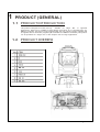
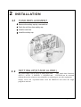
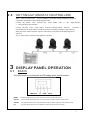
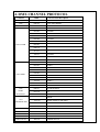
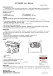
Mini Spot Moving Head
HS-LMS30
USER MANUAL
1
T
ABLE OF CONTENTS
P AR T 1
P R O D U CT ( G E N E R AL ) . . . . . . . . . . . . . . . . . .. . . . . . . . . . . . . . .. . . . . . . . . . .. . . . . .. . . . . . . . 1
1.1--PRODUCT INTRODUCTION............................................................... 1
1.2--PRODUCT OVERVIE W..................................................................... 2
1 . 3 - - T E C H N I C AL S P E C I F I C AT I O N S . . . . . . . . . . . . . . . . . . . . . . . . . . . . . . . . . . . . . . . . . . . . . . . . . . . . . . . . . . 3
1 . 4 - - P H O T O M E T R I C D AT A . . . . . . . . . . . . . . . . . . . . . . . . . . . . . . . . . . . . . . . . . . . . . . . . . . . . . . . . . . . . . . . . . . . . . . . 3
1 . 5 - - S AF E T Y W AR N I N G . . . . . . . . . . . . . . . . . . . . . . . . . . . . . . . . . . . . . . . . . . . . . . . . . . . . . . . . . . . . . . . . . . . . . . . . . . . 3
P AR T 2 I N S T AL L AT I O N . . . . . . . . . . . . . . .. . . . . . . . . .. . . .. . . . . . . . . . . . . . .. . . . . . . . . . .. . . . . .. . . . . . . . . 4
2 . 1 - - F US E RE P L ACE M E N T. .. . .. . .. .. . .. . .. .. . .. .. . .. .. . .. .. . .. . .. .. . .. . .. .. . .. . .. .. . .. .. . .. .. . .. .. . .
4
2 . 2 - - S E TTI NG UP ( S TAND AL O NE ) . . .. .. . .. . .. .. . .. .. . .. .. . .. .. .. . .. . .. .. . .. . .. .. . .. .. . .. .. . .. .. . ..
4
2 . 3 - - L E D P CB REP L ACE M ENT. . . . . .. . .. .. . .. .. . .. .. . .. .. . .. . .. ... . .. . .. .. . .. . .. .. . .. .. . .. .. . .. .. . .. ..
5
2 . 4 - - S E TTI NG UP ( M AS TE R / S L AV E ) . . . . . .. . .. .. . .. .. . .. . .. .. . ... . .. . .. .. . .. . .. .. . .. .. . .. .. . .. .. . ....
6
6
2 . 5 - - S E TTI NG UP ( DM X 5 1 2 CO NTRO L L E R. . . . .. . .. .. . .. . .. ... . .. . .. .. . .. . .. .. . .. .. . .. .. . .. .. . ..
P AR T 3
D I S P L AY P AN E L O P E R AT I O N . . . . . . . . . . . . . . . . . . . . . .. . . . . . . . . . .. . . . . .. . . . . . . . . . 7
3 . 1 - - B AS I C. . . .. . .. .. . .. .. . .. . .. ... . .. . .. .. . .. . .. .. . .. .. . .. .. . .. .. . .. . .. .. . .. . .. .. . .. . .. .. . .. .. . .. .. . .. .. . .. .
7
3 . 2 - - M E NU.. . .. .. . .. .. . .. .. . .. . .. .. . .. . .. .. . .. . .. .. . .. .. . .. .. . .. .. . .. . .. .. . .. . .. .. . .. . .. .. . .. .. . .. .. . .. .. . .. .
7
3 . 3 - - I NTRO . . . . . . .. .. . .. .. . .. . .. ... . .. . .. .. . .. . .. .. . .. .. . .. .. . .. .. . .. . .. .. . .. . .. .. . .. . .. .. . .. .. . .. .. . .. .. . .. .
9
3 . 4 - - I NV E RT. . . . .. .. . .. .. . .. .. . .. .. . .. . .. .. . .. . .. .. . .. .. . .. .. . .. .. . .. . .. .. . .. . .. .. . .. . .. .. . .. .. . .. .. . .. .. . .. . 9
3 . 5 - - R ANG E . . . . .. . .. .. . .. .. . .. .. .. . .. . .. .. . .. . .. .. . .. .. . .. .. . .. .. . .. . .. .. . .. . .. .. . .. . .. .. . .. .. . .. .. . .. .. . .. 1 0
3 . 6 - - S P E CI AL . . . . . .. . .. .. . .. .. . ... . .. . .. .. . .. . .. .. . .. .. . .. .. . .. .. . .. . .. .. . .. . .. .. . .. . .. .. . .. .. . .. .. . .. .. . . 1 0
3 . 7 - - E DI T. . . . .. . .. .. . .. .. . .. .. . .. . .. . .. . .. .. . .. . .. .. . .. .. . .. .. . .. .. . .. . .. .. . .. . .. .. . .. . .. .. . .. .. . .. .. . .. .. . .. .1 1
3 . 8 - - DE F AUL I T. . . . . .. . .. .. . .. .. .. . .. . .. .. . .. . .. .. . .. .. . .. .. . .. .. . .. . .. .. . .. . .. .. . .. . .. .. . .. .. . .. .. . .. .. . .. .11
P AR T 4
U S I N G A D M X5 1 2 C O NT R O L L E R . . . . .. . . . . . . . . . . . . . .. . . . . . . . . . .. . . . . .. . . . . . . .1 2
4 . 1 - - B AS I C AD DRE S S I NG . .. . .. . .. .. . .. . .. .. . .. .. . .. .. . .. .. . .. . .. .. . .. . .. .. . .. . .. .. . .. .. . .. .. . .. .. . .. . 12
4 . 2 - - CH AN NE L AS S I G NM EN T. . .. .. . .. . .. .. . .. .. . .. .. . .. .. . .. .. . .. . .. . .. .. . .. . .. .. . .. .. . .. .. . .. .. . .. .
12
P AR T 5 AP P E N D I X . . . . . . . . . . . . . . . . . . .. . . . . . . . . . .. . . . . .. . . . . . . . . . . . . . .. . . . . . . . . . .. . . . . .. . . . . . . 1 5
5 . 1 - - T RO UBL E S HO O TI NG . . .. . .. .. . .. . .. .. . .. .. . .. .. . .. .. . .. . .. .. . .. . .. .. . .. . .. .. . .. .. . .. .. . .. .. . .. . 15
2
1
PRODUCT (GENERAL)
1 . 1 PRODUCT INTRODUCTION
This product is designed for indoor use only.
Suitable for stage. Bar or nightclub
applications. Direct input of DMX512 signal allows the fixtures to be controlled from any
DMX512 controller. The fixture is fully programmable with one custom program available and
is supplied with two automatic programs (all accessible from DMX512 controller).This product
can be operated as a single unit or with multiple units for large applications.
1 . 2 PRODUCT OVERIEW
3
1.3
TECHNICAL SPECIFICATIONS
Electrical
Voltage:AC100-240V, 50/60Hz
Rated Power:75W
LED
LED:1PC(30W white)
Cooling: Forced air convection
Optical System
Focus: Manual linear focus
Dimmer:0-100%
Strobe:0-20Hz
3-facet Prism
FOCUS
Operation
Control mode:DMX512/Master-Slave/Auto/Custom/Sound
LED display
DMX512 CHS: 11 CHS/12CHS
Pan/Tilt
Pan 630 Tilt270
Pan/Tilt speed
User-selectable Pan/ Tilt ranges
Reverse Pan/Tilt movement
Rotating Gobo
7 Gobo(interchangeable)
Gobo-flow effect
Gobo shake
Bi-directional rotation
Color
9 dichroic -filters
Rainbow-flow effect
Other features
Custom program(255 steps)
Size:240x200x354mm
Weight:7kg
4
1.4
PHOTOMETRIC DATA
1.5
SAFETY WARNING
IMPORTANT
【ALWAYSREAD THEUSER MANUAL BEFORE OPERATION.】
【PLEASE CONFIRM THAT THE POWER SUPPLYSTATED ON THE RODUCT
IS THE SAME AS THE MAINS POWER SUPPLT IN YOUR AREA. 】
This product must be installed by a qualified professional.
Always operate the equipment as described in the user manual.
A minimum distance of 0.5m must be maintained between the equipment and combustible
surface.
The product must always be placed in a well ventilated area.
Always make sure that the equipments installed securely.
DO NOT stand close to the equipment and stare directly into the LED light source.
Always disconnect the power supply before attempting and maintenance.
Always make sure that the supporting structure is solid and can support the combined weight
of the products.
The earth wire must always be connected to the ground.
Do not touch the power cables if your hands are wet.
ATTENTION
This product left the place of manufacture in perfect condition. In order to maintain this
condition and for safe operation, the user must always follow the instructions and safety
warnings described in this user manual.
Avoid shaking or strong impacts to any part of the equipment.
Make sure that all parts of the equipment are kept clean and free of dust.
Always make sure that the power connections are connected correct and
secure.
If there is any malfunction of the equipment, contact your distributor immediately.
When transferring the product, it is advisable to use the original packaging in which the
product left the factory.
Shields, lenses or ultraviolet screens shall be changed if they have becomed amaged to such
an extent that their effectiveness is impaired.
The lamp(LED) shall be changed if it has become damaged or thermal deformed
5
2
INSTALLATION
2.1
FUSE REPLACEMENT
Remove the safety cap by a screwdriver.
Fetch the old fuse from safety cap.
Install a new fuse.
Install the safety cap
2.2
SETTING UP(STAND ALONE)
The LED fixture can be used as stand alone unit.
The stand alone functions
AUTO 1, AUTO 2, SOUND 1, SOUND2 and
CUSTOM can be activated
without the need to connect to any controller or connecting to any other equipment.
Simply, access the <operation>menu from the DISPLAY and select the target
program to activate.
6
2 . 3 LED PCB PEPLACEMEMENT
Take off the head cover.
Remove the fan cover, fan, fan supports, heat sink step by step.
Replace the new LED PCB.
Install all parts on the original position.
2.4
SETTING UP(MASTER/SLAVE)
When units are connected in series using DMX512 signal cable connect the units as shown in the
diagram below.
Connect the (male) 3 pin connector side of the DMX cable to the output (female) 3 pin connector
of the first(MASTER) fixture.
Connect the end of the cable coming from the MASTER fixture which will have a (female) 3pin
connector to the input connector of the next fixture consisting of a (male) 3 pin connector.
Then proceed to connect from the output as stated above to the input of the following fixture and
soon.
Set the first unit in the series to one of the STAND ALONE modes as described in section2.2
All other units in the series should be set to <SLAVE>from the <operation>menu.
7
SETTING UP (DMX512 CONTROLLER)
2.5
When units are connected in series to a DMX512 controller and other DMX512 equipment,
connect the equipment as shown in the diagram below.
Connect the (male) 3 pin connector side of the DMX cable t o the output (female)
3 pin connector of the controller.
Connect the end of the cable coming from the controller which will have a (female) 3
pin connector to the input connector of the next fixture consisting of a(male) 3 pin connector.
Then proceed to connect from the output as stated above to the input of the following fixture
and so on.
If over 32pcs fixtures connected ,the amplifier is needed.
3
DISPLAY PANEL OPERATION
3.1
BASIC
The LED fixture is mounted with a LCD display and 4 control buttons.
MENU
Scroll through the main menu or exit from the current sub-menu
ENTER
the currently selected menu or confirm the current function value Scroll
DOWN
through the menu list or decrease the value of the current function value Scroll
UP
through the menu list or increase the value of the current function
8
3.2
MENU
9
4. DMX CHANNEL PROTOCOL
Channels
DMX
CH1
000-255
CH2
000-255
CH3
000-255
PAN/TILT SPEED
000-014
WHITE
015-027
COLOR 1
028-042
COLOR 2
043-054
COLOR 3
055-068
COLOR 4
069-082
COLOR 5
083-097
COLOR 6
098-110
COLOR 7
111-121
COLOR 8
122-127
COLOR 9
128-192
WHOLE WHEEL FORWARD F-S
193-255
WHEEL BACKWARD S-F
000-018
WHITE
019-037
GOBO 1
038-056
GOBO 2
057-075
GOBO 3
076-093
GOBO 4
094-113
GOBO 5
114-132
GOBO 6
133-144
GOBO 7
145-208
WHOLE WHEEL FORWARD F-S
209-255
WHEEL BACKWARD S-F
000-011
NOT ROTATION
012-130
F-S
131-255
S-F
000-011
WHITE
012-030
RESET AFTER 10 SECOND
031-250
SHUTTER S-F WHITE
251-255
WHITE
000-255
LINEA DIMMING
CH4 COLOR
CH5 GOBO
CH6
GOBO
ROTATION
CH7
STROBOFLASH
CH8 DIMMING
Control Content Description
PAN MOVEMENT
TILT MOVEMENT
CH9:
000-255
X 16bit
CH10:
000-255
Y 16bit
CH11 PRISM
000-255
OPEN
CH12 FOCUS
000-255
LINEAR FOCUS
10
5.APPENDIX
Technical Specification
WEIGHT&DIMENSIONS
Length............................................................................................250mm
Width..............................................................................................240mm
Height.............................................................................................390mm
Packing size.............................................................
410x330x280mm
Net weight..........................................................................................6kgs
Gross weight ................................................................................ 7.3kgs
POWER
Powersettings......................................................220V50Hz/60Hz
Fuse........................................................................................2A220V
Consumption...............................................................................80W
LIGHT SOURCE
1 X 30W WHITE............................
COLOR...........................................................
LAMP LIFE: 50,000Hrs
CONTROL & PROGRAMMING
Data output................................................locking3-pinXLRmalesocket
Datainput............................................locking3-pinXLRfemalesocket
Protocols...............................................................................DMX-512
DMX channels..................................................................................12
11


![[PMID703C] User Manual [FINAL] 20121101](http://vs1.manualzilla.com/store/data/005666959_1-067077325a260bbbb3ca6efa56d2ba06-150x150.png)