1
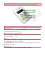
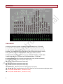
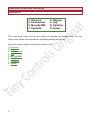
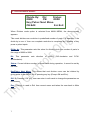
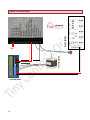
Indexing Controller Document: Operation Manual Document #: T06 Document Rev: 3.0 Product: Indexing Table controller Product Rev: 3.0 Created: Jan-2013 Updated: Dec- 2014 THIS MANUAL CONTAINS INFORMATION FOR INSTALLING AND OPERATING THE FOLLOWING PRODUCT: INDEXING CONTROLLER “TINY CONTROLS” AND THE TINY CONTROLS COMPANY’S LOGO ARE COPYRIGHTS OF TINY CONTROLS PVT. LTD. OTHER TRADEMARKS, TRADE NAMES, AND SERVICE MARKS OWNED OR REGISTERED BY ANY OTHER COMPANY AND USED IN THIS MANUAL ARE THE PROPERTY OF THEIR RESPECTIVE COMPANIES. TINY CONTROLS PRIVATE LIMITED C-55, NISHAT PARK, KAKROLA MOR, NEW DELHI, INDIA – 110078 WEB: http://www.tinycontrols.com PHONE: +91-991-119-3210 1 CONTENTS Item GENERAL DESCRIPTION LOCATION OF COMPONENTS TERMINALS OPERATING THE INDEXING CONTROLLER 1. MAIN MENU SCREEN 2. DIVISION MODE SCREEN 3. DEGREE MODE SCREEN 4. CONTINUOUS MODE SCREEN 5. JOG MODE SCREEN 6. MOVE BY MM SCREEN 7. PROGRAM RUN MODE SCREEN 8. PROGRAM EDIT MODE SCREEN 9. SETUP SCREEN EXAMPLE PROGRAM CONNECTION DIAGRAM 2 Page # 3 4 5 6 6 7 8 9 10 11 12 13 16 18 19 GENERAL DESCRIPTION Indexing controller (or Indexer) is a versatile, programmable controller intended to control rotary tables. The controller can also be used for several custom operations. It can work either in simple indexing modes like dividing mode and degree mode or fully programmable with I/O mode. In programmable mode, the “program” can be a maximum length of 70 instructions. As NESTED LOOPS are also supported, the actual program is capable of performing a variety of complex operations. The following commands are supported (see Pgm Edit section for more details): MOTION SETUP : CCW, CW, SPEED, ACC, SETDIV MOTION COMMANDS : MOVETODEG , MOVEBYDEG, MOVETODIV, MOVEBYDIV, CONT_START, CONT_STOP CHECK INPUTS : WAIT_IN1, WAIT_IN2 CHECK KEYPAD : WAIT_ANY_KEY CHANGE OUTPUTS : OUT1LOW, OUT1HIGH, OUT2LOW, OUT2HIGH, OUT3LOW, OUT3HIGH RECURSION : LOOPFOR, LOOPFOREVER, LOOPEND DWELL : WAIT_SEC OTHER : NOP, END, HOME, JOG SPECIFICATION/FEATURES 3 Supply Voltage: AC mains supply Max Pulse Rate: 40 KHz Overall Size: 120mm x 195mm x 80 mm Mounting: Panel mount Inputs: 2 Proxy + 2 General purpose [TOTAL 4] Outputs: 2 for motor (STEP/DIR) + 2 Activity + 3 General purpose [TOTAL 7] Display: 20x4 line alphanumeric Max Operating Temperature: 55 deg C LOCATION OF COMPONENTS: Major components of the Indexing Controller 4 3 2 1 The description of these components is as following: 1. NUMERIC KEYS (0-9) Numeric keys are used for entering the numeric values in edit mode. In some modes, these serve alternate functions too. 2. NAVIGATION KEYS (UP, DOWN, RIGHT, LEFT) In edit mode, these keys are used to navigate the cursor. In some modes, these serve alternate functions too. 3. OK & Esc Pressing OK key in any mode allows the user to enter in edit mode. In edit mode, pressing OK key saves the modified values in EEPROM. Esc and edit backs the user out of menus/mode. Pressing repeatedly will return the control to the main menu. 4. LCD DISPLAY (20x4) This LCD indicates all the information related to MENUS or MODES. 4 TERMINALS PIN NUMBER 1: Ground (Common ground, Connect to STEPPER DRIVER eq. TSTEP-087) 2: +5V OUTPUT (Max 100mA can be sourced if required by external circuit) 3: +12V OUTPUT (Max 100mA can be sourced if required by external circuit) 4: HOME / IN1 SWITCH0 (Connect output of N/O, NPN type proximity switch) 5: IN2_SWITCH (Connect output of N/O, NPN type proximity switch) 6: MOTOR STEP PULSE OUTPUT (Connect to STEPPER DRIVER eq. TSTEP-087) 7: MOTOR DIR OUTPUT (Connect to STEPPER DRIVER eq. TSTEP-087) 8: ACKNOWLEDGE OUTPUT (Active low pulse after every move completion) 9: ACTIVITY OUTPUT (Active low pulse while move) 10: OUTPUT1 (General purpose output pin) 11: OUTPUT2 (General purpose output pin) 12: OUTPUT3 (General purpose output pin) 13: EMERGENCY_SWITCH (Active low emergency stop input) 14, 15, and 16: Serial communication Pins for future use, do not connect anything to these. 17: AC IN (220V MAINS INPUT, handle with care) 18: AC IN (220V MAINS INPUT, handle with care) 5 OPERATING THE INDEXING CONTROLLER MAIN MENU: 1: 3: 5: 7: Division Continuous MovebyMM PgmEdit 2: 4: 6: 9: Degree Jog PgmRun Setup This is the Home screen and all menu options to navigate are available here. You can return to this screen from anywhere by repeatedly pressing the Esc key. Press the number relating to the mode you want to use. 1: Division 2: Degree 3: Continuous 4: Jog 5: MovebyMM 6: PgmRun 7: PgmEdit 9: Setup 6 1. DIVISION MODE MENU: Divide By: Dir: Status: 0008 CW 0000 Key/Pulse: Next Move OK:Edit Esc:Exit When Division mode option is selected from MAIN MENU, the above screen appears. This mode divides one revolution in predefined number of parts. For example, if the divide by is num ‘x’ then one complete revolution is completed by x number of key press or pulse inputs. Divide by: This parameter sets the value for dividing circle into number of parts in the range of 0002 to 9999. Dir: This parameter sets direction of motion (CW-clockwise and CCW- anticlockwise). Status: Current division number is shown here during operation; it cannot be set by the user. Key/Pulse: Next Move: This shows that next division move can be initiated by giving pulse to the INPUT pin or pressing any key (Except OK and Esc). OK: By Pressing “OK” key, user can enter in edit mode to change the parameters on this screen. Esc: This key is used to Exit from current menu and takes the user back to Main Menu. 7 2. DEGREE MODE MENU: Move Deg: Dir: Status: 360.0 CW 000.0 Key/Pulse: Next Move OK:Edit Esc:Exit When Degree mode option is selected from MAIN MENU, above screen appears. This mode is used whenever the movement is required in degree. On each pulse (or key press) motor is moved by degrees SET. For example, if set value for move degree is 090.0 then on each pulse it moves 90 degrees. Move Deg: This parameter sets the value to move in degrees; it can be set from 0.1 degrees to 999.9 degrees. Dir: This parameter is used for setting direction (CW-clockwise and CCW-anticlockwise). Status: Current division number is shown here during operation; this cannot be set by the user. Key/Pulse or Next Move: This shows that next division move can be initiated by giving pulse to the INPUT pin or pressing any key (Except OK and Esc). OK: By Pressing “OK” key, the user can enter in edit mode to change the parameters on this screen. Esc: This key is used to Exit from current menu. It takes the user back to Main Menu. 8 3. CONTINUOUS MODE MENU: Speed: RPM Dir: Action: 1200 CW St/Stop Key/Pulse: Start / Stop OK: Edit Esc: Exit When Continuous mode option is selected from MAIN MENU, the above screen appears. It shows the value set for Speed, Direction and Action. On each pulse, input or key press starts or stops the motor. This mode is used whenever continuous movement is required. Speed-RPM: This parameter sets velocity that the motor achieves. The range of velocity is from 1 to 1200 (its max value depends on Gear ratio and the steps/rev). Dir: This parameter is used for setting direction (CW-clockwise and CCW-anticlockwise). Key/Pulse: It shows the movement by the input set in Action parameter. Action: This parameter is used for setting Action. Action has 2 options: St/Stp: On alternate pulses (or any navigation key press), motor starts/stops. Reverse: On alternate pulses (or navigation Key press), motor starts and stops but every time the motor starts in reverse direction. OK: Press “OK” key to enter in edit mode. This allows the user to change the parameters on this screen. Esc: Press Esc to exit from current menu to main menu. 9 4. JOG MODE MENU: Cont.jog: Right/Left Cont.Speed:10 Up/Down 1: +0.1 2: +1 3: +10 6: -0.1 7: -1 4: -10 When Jog mode option is selected from MAIN MENU, the above screen appears. Jog mode is primarily used to position the table before entering “Program” mode. Actually by calling “JOG” command, the adjustment can also be done in between program while program is running. Keys: These keys are used for continuous movement of table. These keys are used to set the speed for continuous movement. [1], [6]: Move the table CCW / CW by 0.1 degree for each press. [2], [7]: Move the table CCW / CW by 1 degree for each press. [3], [8]: Move the table CCW / CW by 10 degree for each press. Esc: To return to MAIN MENU. If this command was called when “program” is running, pressing Esc key returns and resumes program where it was left. 10 5. Move by MM MODE MENU: MovebyMM Dir 001.0 CW Key/Pulse: Next Move OK: Edit Esc: Exit When “Move by mm” mode option is selected from MAIN MENU, above screen appears. It shows the set value for Move by MM and DIR. On each pulse input or key press, motor move by mm is set above. This mode is used whenever the linear movement is required. MovebyMM: This parameter is used for setting value to move in MM, it can be set from 1 MM to 999.9 MM. Dir: This parameter is used for setting direction (CW-clockwise and CCW-anticlockwise). Key/Pulse or Next Move: This shows that action can be initiated by giving pulse to the INPUT pin or pressing any key (Except OK and Esc). OK: By Pressing “OK” key, the user can enter edit mode to change the parameters on this screen. Esc: This key is used to Exit from current menu and takes user back to Main Menu. 11 6. Pgm Run MODE MENU: Run: Speed: Position: 0000 00000 ------------ Status ------------ In program run mode, the above screen is displayed. It shows current position and speed of motion that takes place. And whenever controller waits for any input, it is displayed on status. 12 7. PgmEdit MODE MENU: List of commands CCW When this command is set, motion takes place in anticlockwise direction. CW When this command is set, motion takes place in Clockwise direction. HOME This command is used for home purpose. Before using this command, direction must be set. JOG This command is used for initial setting of table position using jog mode. WAIT_IN1 When this command is used, next command takes place after IN1_SWITCH is pressed. WAIT_IN2 When this command is used, next command takes place after IN2_SWITCH is pressed. WAIT_ANY_KEY When this command is used, next command takes place after ANY_KEY is pressed. OUT1LOW This command is used to set the OUTPUT_1 low. (The OUTPUT_1 pin will be at low level or 0V.) OUT1HIGH This command is used to set the OUTPUT_1 high. (The OUTPUT_1 pin will be at high level or 5V.) OUT2LOW This command is used to set the OUTPUT_2 low. (The OUTPUT_2 pin will be at low level or 0V.) OUT2HIGH This command is used to set the OUTPUT_2 high. (The OUTPUT_2 pin will be at high level or 5V.) OUT3LOW This command is used to set the OUTPUT_3 low. (The OUTPUT_3 pin will be at low level or 0V.) OUT3HIGH This command is used to set the OUTPUT_3 high. 13 (The OUTPUT_3 pin will be at high level or 5V.) CONT_START This command is used for continuous motion at set SPEED. CONT_STOP This command is used to stop continuous motion. SPEED (VALUE) RANGE 1 TO 1200 This command is used to set the maximum speed, which the motor achieves while in operation. ACCEL (VALUE) RANGE 0001 TO 0020 This command is used to set acceleration. MOVETODEG (VALUE) RANGE 000.0 TO 999.9 This command is used when movement is required in absolute degree. MOVEBYDEG (VALUE) RANGE 000.0 TO 999.9 This command is used when movement is required in relative degree. SETDIV (VALUE) RANGE is 000.0 TO 999.9 This command is used to set division. MOVETODIV (VALUE) RANGE 000.0 TO 999.9 This command is used when movement is required in absolute division. MOVEBYDIV (VALUE) RANGE 000.0 TO 999.9 This command is used when movement is required in relative division. WAIT_mSEC (VALUE) RANGE 0001 TO 9999 This command is used to generate delay between two commands, 1000 is 1 second. LOOPFOR (VALUE) RANGE 0001 TO 9999 This command is used for looping and must be end with LOOPEND. LOOPFOREVER This command is used for infinite loop. LOOPEND This command is used to end loop instruction and every loop (loopfor or loopforever) must be end with LOOPEND. NOP This command is used for no operation. It can be used to temporarily remove an instruction by replacing it with a NOP. 14 END This command is used to end program and every program must have END command at last. >01 CCW 02 SPEED 03 END OK: Save 0001 Esc: Exit Editing the Program Allows the user to enter a program or edit an existing one. The screen shows a window of 4 lines on the program along with a cursor (>). Lines begin with the current line number followed by the command and its value. With an empty program, the screen looks like the one shown below. >01 ---------------02 ---------------03 ---------------OK: Save Esc: Exit The cursor shows current position and next to cursor, current line is displayed. In above figure cursor is currently on line one so command can be entered by pressing right-left navigation keys and values can be entered by num key [0] - [9]. And line current line can be changed using up and down navigation keys. 15 8. SETUP MODE MENU: Gear Ratio: Steps/Rev: Steps/mm: OK: Save 001.0 2000 2000 Esc: Exit When setup option is selected from MAIN MENU, the above screen appears. With the help of Navigation keys (UP, DOWN, RIGHT, LEFT) and other keys, parameter can be changed. The changed parameter can be saved with OK or discarded by Esc. Gear Ratio: This parameter is used for setting gearing ratio. And the range for gear ratio is (001.0 to 999.9). Step/Rev: This parameter is used for setting Steps required for single revolution. And the range for step/rev is 200 to 9999. Step/MM: This parameter is used for setting Steps required for 1 mm of linear motion. And the range for step/rev is 1 to 9999. Acceleration: This parameter is used for setting Acceleration range for acceleration is 01 to 20. Speed: This parameter is used for setting Max Speed (this is the maximum speed motor will achieve). And the range for Max Speed is 1 to 1200. Home Speed: This parameter is used for setting Max Home Speed (this is the maximum speed motor will achieve while home). And the range for Max Home Speed is 1 to 1200. Direction: This parameter is used for setting direction CW-clockwise and CCWanticlockwise. Boot Mode: This parameter is used for setting the Boot up mode for the controller. It can be set to any mode (listed in the MAIN MENU). For example if it is set to “PgmRun” mode, the controller bypasses the Main Menu screen and directly starts in RUN mode. It starts executing Program stored in Memory. 16 Splash Screen: This parameter is used to turn off/on initial splash screen. One use of making splash screen off can be fast boot up time. Factory Reset: This parameter is used for resetting all parameters to Factory Defaults. It can be used if you want to start over. It also loads a SAMPLE program erasing any user program stored on volatile memory. Use of Keys in Setup menu: Left-Right navigation keys: These keys are used for moving cursor to next parameter. Up-Down navigation keys: These keys are used for moving cursor to next parameter. Numeric keys 0-9: To enter the number. OK Key: Save and return to MAIN MENU. Esc Key: Cancel and return to MAIN MENU. 17 Example 1: We have to move a disk 36° with 400 RPM speed and acceleration 1 whenever a pulse is received from proxy switch. Since I am using TSTEP-087 stepper motor drive which is using micro stepping, it takes 2000 pulses for one revolution and disk is directly mounted on the motor shaft. Selection of Gear Ratio and Steps/ Rev: Since disk is directly mounted on the motor shaft so SET GEAR RATIO 1. As TSTEP-087 takes 2000 steps to move the motor one revolution so SET STEPS/REV 2000. ACCEL SPEED DIR CW LOOPFOREVER MOVEBYDEG LOOPEND END 18 1 0400 030.0 CONNECTION DIAGRAM POWER SUPPLY STEPPER MOTOR ~AC~ STEPPER DRIVE 19


![BOS User`s Manual [v 1.00]](http://vs1.manualzilla.com/store/data/005878726_1-a93b95814f153b2994a972b38c1cdb16-150x150.png)