1
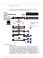
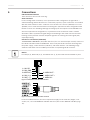
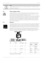
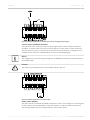
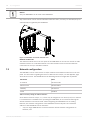
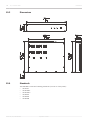
DPM 8016
en | Operation manual
DPM 8016
Table of Contents | en
3
Table of contents
1
Safety notes
4
2
Brief description
7
3
System description
4
Scope of delivery and warranty
12
5
Installation
13
5.1
Front
13
5.2
Back
14
5.3
Installation
15
6
Connections
17
8
6.1
Power supply voltage
18
6.2
Ethernet
18
6.3
REMOTE CAN BUS
19
6.4
Control port
22
7
Configuration
25
7.1
Installing extension cards
25
7.2
Network configuration
26
8
Operation
28
9
Maintenance
29
10
Technical data
30
10.1
Power consumption
31
10.2
Block diagram
33
10.3
Dimensions
34
10.4
Standards
34
11
Appendix
35
11.1
Ethernet basics
35
11.2
Table of IP addresses
37
Operation manual
16-Dec-13 | 02 | F01U259190
4
en | Safety notes
1
DPM 8016
Safety notes
Danger!
The lightning symbol inside a triangle notifies the user of high-voltage, uninsulated lines and
contacts inside the devices that could result in fatal electrocution if touched.
Warning!
!
An exclamation mark inside a triangle refers the user to important operating and service
instructions in the documentation for the equipment.
1.
Read these safety notes.
2.
Keep these safety notes in a safe place.
3.
Heed all warnings.
4.
Observe all instructions.
5.
Do not operate the device in close proximity to water.
6.
Use only a dry cloth to clean the unit.
7.
Do not cover any ventilation slots. Always refer to the manufacturer's instructions when
installing the device.
8.
Do not install the device close to heaters, ovens, or other heat sources.
9.
Note: The device must only be operated via the mains power supply with a safety ground
connector. Do not disable the safety ground connection function of the supplied power
cable. If the plug of the supplied cable does not fit your mains socket, please contact
your electrician.
10. Ensure that it is not possible to stand on the mains cable. Take precautions to ensure the
mains cable cannot become crushed, particularly near the device connector and mains
plug.
11. Only use accessories/extensions for the device that have been approved by the
manufacturer.
12. Unplug the device if there is risk of lightning strike or in the event of long periods of
inactivity. However, this does not apply if the device is to be used as part of an
evacuation system!
13. Have all service work and repairs performed by a trained customer service technician
only. Service work must be carried out immediately following any damage such as
damage to the mains cable or plug, if fluid or any object enters the device, if the device
has been used in rain or become wet, or if the device has been dropped or no longer
works correctly.
16-Dec-13 | 02 | F01U259190
Operation manual
DPM 8016
Safety notes | en
5
14. Please ensure that no dripping water or spray can penetrate the inside of the device. Do
not place any objects filled with fluids, such as vases or drinking vessels, on top of the
device.
15. To ensure the device is completely free of voltage, unplug the device from the power
supply.
16. When installing the device, ensure that the plug is freely accessible.
17. Do not place any sources of open flame, such as lit candles, on top of the device.
18. This PROTECTION CLASS I device must be connected to a MAINS socket with a safety
ground connection.
Caution!
Use only manufacturer-approved carts, stands, brackets, or tables that you acquired together
with the device. When using carts to move the device, make sure the transported equipment
and the cart itself cannot tip over or cause injury or material damage.
IMPORTANT SERVICE INFORMATION
Caution!
This service information is for use by qualified service personnel only. To avoid the risk of
!
electric shock, do not perform any maintenance work that is not described in the operating
instructions unless you are qualified to do so. Have all service work and repairs performed by
a trained customer service technician.
1.
Repair work on the device must comply with the safety standards specified in EN 60065
(VDE 0860).
2.
A mains isolating transformer must be used during any work for which the opened device
is connected to and operated with mains voltage.
3.
The device must be free of any voltage before performing any alterations with upgrade
sets, switching the mains voltage, or performing any other modifications.
4.
The minimum distance between voltage-carrying parts and metal parts that can be
touched (such as the metal housing) or between mains poles is 3 mm, and must be
observed at all times.
5.
The minimum distance between voltage-carrying parts and circuit parts that are not
connected to the mains (secondary) is 6 mm, and must be observed at all times.
6.
Special components that are marked with the safety symbol in the circuit diagram (note)
must only be replaced with original parts.
7.
Unauthorized changes to the circuitry are prohibited.
8.
The protective measures issued by the relevant trade organizations and applicable at the
place of repair must be observed. This includes the properties and configuration of the
workplace.
9.
Observe the guidelines with respect to handling MOS components.
Danger!
SAFETY COMPONENT (MUST BE REPLACED BY ORIGINAL PART)
Operation manual
16-Dec-13 | 02 | F01U259190
6
en | Safety notes
DPM 8016
Caution!
!
Risk of explosion if battery is not replaced correctly. Must be replaced only with the same or
equivalent type of battery.
16-Dec-13 | 02 | F01U259190
Operation manual
DPM 8016
2
Brief description | en
7
Brief description
The DPM 8016 is the modular, network-capable central unit of the PROMATRIX 8000 system.
The system can be adjusted to requirements via the eight slots for audio input, audio output
or message manager modules. The DPM 8016 contains all necessary audio functions and is
responsible for controlling and monitoring the complete PROMATRIX 8000 system. A single
DPM 8016 can manage up to 16 call stations and up to 500 loudspeaker circuits; in larger
systems, up to ten DPM 8016 controllers can be linked with each other via a digital audio and
control bus.
Operation manual
16-Dec-13 | 02 | F01U259190
8
en | System description
DPM 8016
System description
3
This chapter explains the basic configuration of the PROMATRIX 8000 system and its most
important functions. The following block diagram shows a PROMATRIX system with DPM 8016
central unit, call stations, audio equipment, amplifiers, a power supply, relay cards and
loudspeaker circuits, as well as control cards for external signals.
AUDIO SOURCE
DPC 8015
DPC 8120
DPM 8016
DCS 400
PC
ETHERNET
DPM 8016
REMOTE CAN BUS
ETHERNET
COBRA NET
AUDIO (LINE LEVEL)
AUDIO (100 V)
PCA
DPA 8150
DPA 8225
DPA 8412
Figure 3.1: PROMATRIX 8000
General overview
The DPM 8016 is the modular, network-capable central unit of the PROMATRIX 8000 system.
The system can be adjusted to system requirements via the 8 slots for audio input, audio
output or message manager modules. The DPM 8016 contains all necessary audio functions
and is responsible for controlling and monitoring the complete PROMATRIX 8000 system. The
type and number of connected audio sources, amplifiers, and relay cards are extremely
variable, and can be adjusted to individual requirements. A single DPM 8016 can manage up to
16 call stations and up to 500 zones; in larger systems, up to 10 DPM 8016 controllers can be
linked with each other via a digital audio and control bus. Control inputs and outputs can be
16-Dec-13 | 02 | F01U259190
Operation manual
System description | en
DPM 8016
9
used for controlling and monitoring functions, and allow both the logic level and the analog
level to be processed and generated. Configuration is performed on a PC using the IRIS-Net
software, which also provides access to system documentation and the required user
interface. A configuration can be changed at any time, and adjusted to new circumstances
without having to modify the system installation. A PC is required only for loading or changing
the configuration; it does not need to be connected during live operation. In many cases,
however, a permanently connected PC is helpful; for example, to provide detailed status
displays and log reports, real-time loudspeaker and sound control, or for remote diagnosis and
maintenance via the network. The user interface can be individually tailored, and up to 32
password levels can be assigned.
Audio routing
A digital 36 x 16 audio matrix is integrated into the DPM 8016. Up to 16 local audio inputs, 4
internal generators, and 16 optional CobraNet network inputs are available. The 16 matrix
outputs can be used as local audio outputs, or optionally provided via the CobraNet network.
This means 16 audio channels can be used in parallel, and connected to the amplifiers. Each
loudspeaker circuit can be connected with amplifier outputs via a relay matrix, which allows
for 500 loudspeaker zones. The DPM 8016 manages the audio signals, and distributes them
according to priority. In addition to the call stations, other audio sources can also be
connected to the audio inputs such as microphones, mixing desks, CD players, MP3 players,
tuners, and so on. A number of different connections are available for optimum adjustment.
Audio processing
The DPM 8016 provides separate volume controls with a mute function for each audio input
and audio output. Each audio input has a 3-band equalizer and a compressor for optimal
sound adjustment of the audio sources. All outputs are fitted with a 5-band equalizer and a
limiter. For the equalizers, the operator can select from six different filter types for each band
filter (peak, low-shelving, high-shelving, high pass, low pass, all pass). Volume levels, filter
parameters, and so on are set on the PC during configuration. However, these can also be
changed in real-time during operation using the graphical user interface, the special keys for
the call stations, or external operating controls.
Signal generators
The DPM 8016 provides four signal generators: Two independent generators for generating
alarm signals and two independent generators for generating gong signals. Operators can
choose between 24 alarm types and six gong types that are available ex-works.
Call stations
The call stations of the DPC 8000 series are used mainly for announcements, but are also used
for manual control of the PROMATRIX 8000 system. Possible call station functions include
circuit/group selection, announcements, program allocation, triggering gong and alarm signals,
and voice mail playback. However, special commands such as volume control, monitor
selection, preset switching, light control, function displays, and much more are also possible.
The call stations can therefore also be configured for general control tasks. If an
announcement is to be routed through a loudspeaker circuit that is already occupied, the
system issues an occupied notification (i.e., the BUSY-LED flashes). If the call station
concerned has a higher priority, it can interrupt the lower-priority call from the other call
station/signals. The system naturally includes safeguards relating to this: The user is notified
that the system is occupied when selecting the circuit (before the interruption) by the flashing
BUSY-LED. The user can now decide whether to interrupt the signal immediately, or whether
to wait until the end of the active announcement. Each zone selection key has two LEDs: A
Operation manual
16-Dec-13 | 02 | F01U259190
10
en | System description
DPM 8016
green LED shows the current selection, and a yellow LED shows the current status of the zone
(occupied, free, alarm active). System information or error messages can be displayed on the
call station's illuminated graphic display.
Control inputs and outputs
The PROMATRIX 8000 system has analog and digital control inputs and outputs. The control
inputs allow a connection to be established to fire alarm systems, intruder alarm systems, or a
control desk. However, it is also possible to connect external switches, controllers, or rotary
encoders, or to retrieve output messages from external equipment (power supply, power
amplifiers, and so on). The control outputs allow the user to activate/deactivate external
devices, trigger signals and events, remotely control doors, gates, and roller blinds, generate
an analog level for media control, and much more.
Automatic control
The DPM 8016 contains a quartz-controlled real-time clock that can be switched to DCF77
radio clock operation via an optional antenna (radio receiver NRS 90193). The system clock
automatically recognizes leap years; in DCF77 mode, it also automatically switches to daylightsaving time. Up to 40 external slave clocks can be controlled by the system clock. A special
output for polarity switch impulses, which is protected against short circuits, is integrated in
the DPM 8016 for this purpose. Slave clocks are automatically adjusted if a time difference
between the slave clocks and the system clock is detected, for example after a power failure
or in the event of manual input. Together with the calendar function, the system clock can be
used to execute functions such as a break gong, music, gate control, light control, and so on.
These functions can be programmed for specific days, but can also be implemented on an
hourly, daily, weekly, monthly, and annual basis. Up to 500 time-controlled events can be
entered. Functions and parameters can be connected in an internal sequence. The TaskEngine
in the DPM 8016 provides a graphic display that allows the user to combine processes
individually. One example would be a gong signal to be transmitted at a certain volume and
with a specific priority in specific call groups, and which simultaneously activates a control
output. In this case, the process consists of the “gong” and “analog output” function blocks
combined with the parameters of gong type, volume, priority number, call group number, as
well as the type and number of the control output. The processes can be triggered via special
function keys on the call stations or via control inputs, but can also be linked to clock or
calendar dates.
Interfaces
In addition to the control inputs and outputs, the PROMATRIX 8000 system also includes other
interfaces. The call stations are connected to the DPM 8016 via the PCA bus (CAN bus
standard). Up to four call stations can be connected via one PCA bus. The power amplifiers
and the DCS 400 control system are controlled and monitored by the DPM 8016 via an
additional, independent CAN bus interface. The connection to a PC is established via an
Ethernet interface. The Ethernet interface is used to connect several DPM 8016 controllers.
The redundant, optional CobraNet interface is used to transmit audio data.
Security features
The DPM 8016 monitors all internal functions itself, and the connected call stations and power
amplifiers including their connection lines are also monitored by polling and pilot tone. When
using the DPA 8000 POWER AMPLIFIER, loudspeaker lines can be monitored by end-of-line
modules installed at the ends of the lines. The PROMATRIX 8000 system also supports
emergency power operation – in the event of a power failure, the DPM 8016 can assume all
power management functions, that is, all unnecessary internal and external consumers switch
to standby mode, or are deactivated and only reactivated again when required. This greatly
16-Dec-13 | 02 | F01U259190
Operation manual
System description | en
DPM 8016
11
reduces power consumption, and ensures maximum operating time on battery power. Error
messages can be displayed on the call station displays in plain text. A potential-free contact is
used on the DPM 8016 for batch messages.
Operating Instructions
In accordance with the specified and technical details for this product, the DPM 8016 can be
used to control and monitor public address and call systems within the building installation,
as well as for professional audio systems.
The DPM 8016 is not a stand-alone device. The following are the minimum requirements for
operation:
1.
A mains adapter (24 V) sufficiently configured for the system’s power demands.
2.
If the device is to be operated with call stations: The required number of call stations
from the DPC 8000 series (max. 16) and the corresponding connecting cables.
3.
If the audio element of the device is to be used: Power amplifier, preferably from the
DPA 8000 series incl. cabling and loudspeaker with cabling.
4.
If the internal real-time clock is to be synchronized to the DCF77 time signal: An active
DCF77 reception antenna (NRS 90193) incl. cabling. (This feature can be used only in
regions in which the DCF77 signal can be received with sufficient strength, or if
converters from different time information to DCF77 are used.)
5.
If slave clocks are to be controlled: The required number of slave clocks (max. 40) incl.
cabling
6.
If line relays and/or control inputs or outputs are to be used: A DCS system consisting of
a DCS 801R and the required types of DCS cards
Operation manual
16-Dec-13 | 02 | F01U259190
12
4
en | Scope of delivery and warranty
DPM 8016
Scope of delivery and warranty
Number
Component
1
DPM 8016
1
Operating manual
2
CAN terminating resistor (120 Ω)
1
2-pole connector for 24 V DC input (Phoenix PC 5/2-STF1-7.62 – 1777833)
2
12-pole connector for GPIO (Phoenix MC 1.5/12-STF-3.81 – 1827800)
1
Warranty card with safety notes
Table 4.1: Scope of delivery
Warranty
For information regarding the warranty, see www.dynacord.com
16-Dec-13 | 02 | F01U259190
Operation manual
DPM 8016
Installation | en
5
Installation
5.1
Front
13
Number
Element
Description
1
ACTIVE LED
Illuminates green when the digital audio network is
in operation.
2
TIME LED
The green TIME LED indicates the operating status
of the DCF77 radio clock receiver. The following
statuses are possible:
•
Off: No radio clock signal is being received, or
no radio clock antenna is connected. The
system clock is quartz-controlled.
•
On: The radio clock signal is functioning
correctly. The system clock is synchronized via
DCF77.
3
STANDBY LED
Illuminates yellow when the device is in standby
mode.
4
MASTER LED
Illuminates green if this DPM 8016 controller is in
the digital audio network of the master.
5
FAULT LED
This LED illuminates yellow during a reset or in the
event of a watchdog error in the DPM 8016. It also
indicates faults in external system components (end
levels, call stations, relay cards, etc.). The LED is
coupled with the READY contact (see Section
Control port, page 22) on the rear of the device,
which allows any faulty system behavior to be
reported externally.
6
FAULT key
Press the FAULT key to confirm a fault in the system
and deactivate the signal tone.
Operation manual
16-Dec-13 | 02 | F01U259190
14
en | Installation
DPM 8016
Number
Element
Description
7
POWER LED
This LED illuminates green when the voltage supply
of the DPM 8016 (24 V) is connected. The LED
switches off when the DPM 8016 is disconnected
from the voltage supply or if the voltage supply is
switched off or fails.
8
USB interface
Used to connect the DPM 8016 to a PC. For future
applications. See the Section Connections, page 17
5.2
Back
Figure 5.1:
Number
Element
Description
1
Power supply input (DC INPUT
Connection for 24 V DC voltage. See
24/48V)
Section Power supply voltage, page 18
2
CONTROL PORT
See Section Control port, page 22
3
STATUS LED
See Section REMOTE CAN BUS, page
4
REMOTE CAN BUS interfaces
5
RS-232 interfaces
See Section Connections, page 17
6
ETHERNET interface with status
The orange LED illuminates when an
LEDs
Ethernet connection has been
19
established with another device. The
green LED illuminates briefly whenever
data is transferred. See Section
Ethernet, page 18
7
RESET key
Briefly press the RESET key to restart
the DPM 8016. Press the RESET key for
at least 3 seconds to enter service
mode.
8
Network module slot
9
Extension slots
16-Dec-13 | 02 | F01U259190
Operation manual
See Section Installing extension cards,
page 25
DPM 8016
Installation | en
5.3
15
Installation
The DPM 8016 has been developed for horizontal installation in a conventional 19" rack
cabinet. As a rule, the DPM 8016 must be mounted in such a way that the ventilation slots are
not blocked on either side.
Figure 5.2: Air supply and ventilation of the DPM 8016
The ventilation direction runs from left to right when the device is observed from the front. If
possible, devices with the opposite ventilation feed should not be mounted in the same rack/
cabinet. When installing the device in the housing and rack cabinet, ensure there is a free
channel of air between the sides of the DPM 8016 device and the side walls of the cabinet/
rack up to the level of the upper rack or cabinet vent so that the devices are sufficiently
ventilated. There should be free space of at least 100 mm above the cabinet for ventilation.
!
Warning!
The maximum ambient temperature of +45 °C should not be exceeded.
When installing in a cabinet or transport rack, standard installation rails should be used to
prevent the front panel distorting.
The DPM 8016 must be protected from:
•
Dripping water or spray
•
Direct sunlight
•
High ambient temperatures or immediate sources of heat
•
High humidity
•
Large dust deposits
•
Strong vibrations
If these requirements cannot be guaranteed, the device must be regularly serviced to prevent
any outages that could occur as a result of negative ambient conditions. If the DPM 8016 is
moved directly from a cold to a hot location, there is a possibility of condensation forming
inside the device. The device must only be commissioned once it has warmed up to the new
temperature (after around one hour). If a solid object or fluid enters the housing, immediately
disconnect the device from the voltage supply, and have it serviced by an authorized call
station before it is recommissioned.
Front bracket
Attach the DPM 8016 on the front side with four screws and washers as shown in the
following figure.
Operation manual
16-Dec-13 | 02 | F01U259190
16
en | Installation
DPM 8016
Figure 5.3: Attachment on the front panel
When installing in cabinet racks, installation rails should always be used to prevent the front
panel distorting.
16-Dec-13 | 02 | F01U259190
Operation manual
DPM 8016
6
Connections | en
17
Connections
USB and RS-232 interface
These interfaces are used for servicing.
Audio interfaces
For the analog audio connection, use a symmetrical cable configuration (2 signal wires +
shielded braiding) with XLR socket. For connection purposes, 3-pole connectors are included
with the audio extension cards. Conductor cross-sections of 0.14 mm² (AWG26) to 1.5 mm²
(AWG16) can be used. Recommended connecting line: Symmetrical cable configuration with
flexible 2 x 0.14 mm² shielding. Although all analog inputs and outputs of the DPM 8016 can
also have asymmetrical configurations, a symmetrical audio connection cable is a better
alternative. With a symmetrical signal design, the shielding in the cable connects all metal
housings, which prevents external disruption signals from entering the audio signal path,
especially buzzing.
Interface to call stations (PCA BUS)
The PROMATRIX CAN Audio (PCA) BUS interface (of a UI-1 universal input module) connects a
DPC 8015 call station with the DPM 8016. This is an 8-pole RJ-45 connector that integrates
the power supply, control interface (CAN bus), and audio interface. The following image
shows the allocation of the PCA BUS jack and the corresponding RJ-45 connector.
Notice!
For CAN (4, 5), AUDIO IN (3, 6), and AUDIO OUT (7, 8), the leads must be twisted as pairs.
1
1: +24V DC
2: CAN_GND
3: AUDIO IN +
4: CAN_H (+)
5: CAN_L (-)
8
8: AUDIO OUT 7: AUDIO OUT +
6: AUDIO IN -
Figure 6.1: Allocation of the PCA bus interface
Figure 6.2: Allocation of the PCA bus connector
For the PCA BUS interface, the same requirements apply for the used line (length, cross
section, etc.) as for the REMOTE CAN BUS interface (See Section REMOTE CAN BUS, page
19).
Operation manual
16-Dec-13 | 02 | F01U259190
18
en | Connections
DPM 8016
Notice!
The terminating of the PCA BUS in the UI-1 universal input module is configured via IRIS-Net
during system configuration.
6.1
Power supply voltage
The DPM 8016 requires a DC 24 V voltage supply. The scope of delivery includes a 2-pole
connector. Conductor cross-sections of 0.2 mm² (AWG24) to 6 mm² (AWG10) can be used.
Recommended connecting cable: Flexible CU strand, LiY, 1.5 mm².
The maximum power consumed depends on the extension cards inserted into the DPM 8016
and any connected peripheral equipment (e.g., call stations). We recommend using a system
mains adapter from our catalog. The “Power Calculator” tool can be used to calculate the
overall power requirements of a DPM 8016 or a complete PROMATRIX system. The latest
version can be found in the Tools directory on the IRIS-Net CD, or you can request the tool
from our Support department.
6.2
Ethernet
Connecting the DPM 8016 system controller via the Ethernet interface allows the DPM 8016 to
communicate with one or more PCs. This not only allows simple configuration of the DPM
8016 using the delivered IRIS-Net software, but it also allows you to operate and monitor the
entire PROMATRIX 8000 system. Providing that you use the necessary network hardware, the
DPM 8016 can also be operated via a wireless network (WLAN). The Ethernet interface is
provided as an RJ-45 jack (8P8C). Both the 10Base-T and 100Base-TX Ethernet standards are
supported. For the Ethernet interface assignment, see the following diagram and table.
Figure 6.3: Ethernet interface assignment
Pin
1
Name
Tx+
Description
Transmit+
Pair
2
Cable color according to
T568A
T568B
Green stripes
Orange
stripes
2
Tx-
Transmit-
3
Rx+
Receive+
3
Green
Orange
Orange
Green stripes
stripes
6
Rx-
Receive-
Table 6.1: Ethernet interface assignment
16-Dec-13 | 02 | F01U259190
Operation manual
Orange
Green
DPM 8016
Connections | en
19
The following diagram shows the assignment of the Ethernet connector. The diagram shows
the connector from the contact side.
Figure 6.4: Assignment of the Ethernet connector
In both Ethernet standards, the maximum length of a connected cable is 100 meters, with two
twisted wire pairs used in each cable. For 10Base-T, a category 3 cable (unshielded, CAT-3)
must be used, and for 100Base-TX, a category 5 cable (shielded, CAT-5) must be used. When
connecting the DPM 8016 using a patch cable in conjunction with a hub/switch, the cable
wiring must be one to one, i.e., the wire of the cable at pin 1 for one connector is connected
with pin 1 on the other connector; the same process applies to the other pins. The two
standards T568A and T568B are used for the colors of the cable wires, although standard
T568B is more widely used.
LED status lights
The Ethernet interface of the DPM 8016 controller has an orange and a green LED to display
the status of the Ethernet connection. If no network cable is connected, both LEDs remain
unlit. The orange connectivity LED on the left side of the Ethernet interface illuminates once
the DPM 8016 controller has established an Ethernet connection with another device (e.g.,
another DPM 8016 controller or an Ethernet switch). The green network traffic LED on the
right side of the Ethernet interface briefly illuminates each time Ethernet data is transferred.
Crossover cable
When using a crossover cable to connect a DPM 8016 controller with a PC directly, wire-pair 2
must be swapped with wire-pair 3. This creates the necessary switch of sending and receiving
lines; with a hub/switch, this exchange is performed internally.
6.3
REMOTE CAN BUS
The DPM 8016 controller has two RJ-45 jacks for the REMOTE CAN BUS. The jacks are
switched in parallel, and act as an input and for looping the remote network. Standard RJ-45
network cables can be used for cabling within the rack.
For longer cable lengths, observe the CAN guidelines. The CAN bus requires a 120 Ω
connecting jack at both ends. The CAN bus allows different data rates to be used, where the
data rate is indirectly proportional to the bus length. If the network has only a minimal extent,
data rates of up to 500 kbit/s are possible. In larger networks, the data rate will be decreased
(down to the minimum data rate of 10 kbit/s).
Notice!
The data rate is preset to 10 kbit/s.
The following table explains the relationship between data rates and bus lengths/network
size. Bus lengths of over 1000 meters should be implemented only with CAN repeaters.
Data rate (in kbit/s)
Bus length (in meters)
500
100
250
250
Operation manual
16-Dec-13 | 02 | F01U259190
20
en | Connections
DPM 8016
Data rate (in kbit/s)
Bus length (in meters)
125
500
62.5
1000
20
2500
10
5000
Table 6.2: Data rate and bus length of the REMOTE CAN BUS
The following diagrams show the assignment of the CAN jack / CAN connector.
Figure 6.5: Assignment of the CAN jack
Figure 6.6: Assignment of the CAN connector
Pin
Designation
Cable color
T568A
T568B
Orange
2
CAN_GND
Green
4
CAN_H (+)
Blue
5
CAN_L (-)
Blue stripes
7
MONITOR BUS +
Brown stripes
8
MONITOR BUS -
Brown
Table 6.3: Assignment of the REMOTE CAN BUS interface
Cable specification
In accordance with the ISO 11898-2 standard, shielded or unshielded twisted pair cables with
an impedance of 120 Ω should preferably be used as the data transfer cable for the CAN bus.
Terminating resistance of 120 Ω must be provided at both ends as the line. The maximum bus
length depends on the data transmission rate, the type of data transmission cable, and the
number of bus participants.
16-Dec-13 | 02 | F01U259190
Operation manual
Connections | en
DPM 8016
Bus length (in
m)
Data transmission cable
Resistance per unit Cable cross-
0 to 40
40 to 300
Connection
Maximum data
resistance (in
transmission
mΩ)
rate
(in mΩ/m)
section
< 70
0.25 to 0.34 mm² 124
1000 kbit/s at
AWG23, AWG22
40 m
< 60
0.34 to 0.6 mm²
127
500 kbit/s at
AWG22, AWG20
300 to 600
< 40
0.5 to 0.6 mm²
100 m
150 to 300
100 kbit/s at
AWG20
600 to 1000
< 26
21
500 m
0.75 to 0.8 mm²
150 to 300
62.5 kbit/s at
AWG18
1000 m
Table 6.4: Relationships for CAN networks with up to 64 participants
In the event of long cables and several devices on the CAN bus, terminating resistors with ohm
ratings higher than the specified 120 Ω are recommended in order to reduce the resistive load
for the interface drivers, which in turn reduces the voltage loss from one line end to another.
The following table allows an initial estimate to be made for the required cable cross-section
for different bus lengths and a different number of bus participants.
Bus length (in m)
Number of devices on the CAN Bus
32
64
100
100
0.25 mm² or AWG24
0.34 mm² or AWG22
0.34 mm² or AWG22
250
0.34 mm² or AWG22
0.5 mm² or AWG20
0.5 mm² or AWG20
500
0.75 mm² or AWG18
0.75 mm² or AWG18
1.0 mm² or AWG17
Table 6.5: REMOTE CAN BUS cable cross-section
If a participant cannot be directly connected to the CAN bus, a stub line (branch line) must be
used. Since there must always be precisely two terminating resistors on a CAN bus, a stub line
cannot be terminated. This creates reflections, which impair the rest of the bus. To minimize
these reflections, these stub lines should not exceed a maximum individual length of 2 meters
at data transmission rates of up to 125 kbit/s, or a maximum length of 0.3 meters at higher bit
rates. The overall length of all branch lines should not exceed 30 meters.
The following applies:
•
Standard RJ-45 patch cables with 100 Ω impedance (AWG 24 / AWG 26) can be used for
short distances (up to 10 meters).
•
The guidelines specified above for the network cabling must be used when wiring the
racks with each other and for the building installation.
STATUS LED
The STATUS LED is used to check communication across the REMOTE CAN BUS. If the CAN
interface is not in operation, the LED is deactivated. In normal operation, the LED flashes in 2second intervals. The duration for which the LED is illuminated within these 2-second cycles
corresponds to the bus load, i.e., at higher loads, the LED is illuminated for longer during the
2 seconds than at lower bus loads.
Operation manual
16-Dec-13 | 02 | F01U259190
22
en | Connections
DPM 8016
Control port
6.4
The control port on the rear of the DPM 8016 controller is split into two halves. The upper half
has eight freely configurable control inputs, and a DCF77 receiver can also be connected. The
lower half has six freely configurable control outputs and a ready contact, and slave clocks can
also be connected. The scope of delivery includes two 12-pole connectors. Conductor crosssections of 0.14 mm² (AWG26) to 1.5 mm² (AWG16) can be used. Recommended connecting
cable: Flexible CU strand, LiY, 0.25 mm². The control port is configured in IRIS-Net.
Control inputs (CONTROL INPUTS 0-10V)
The upper half of the control port has eight freely programmable control inputs for voltages of
between 0 volts and 10 volts. The inputs are numbered 1 through 8. The DPM 8016 controller
provides its own voltage supply for externally connected control elements, e.g., a
potentiometer. The voltage supply is available at the control port connections for 10V REF and
ground; see the following diagram.
Figure 6.7: Sample application of a control input and use of an analog input signal
The control inputs can also be used as digital control inputs. Internally, the control inputs are
connected to ground via a resistor. If an input is created to the 10 V REF connection or
another, external voltage, the input switches to the active status (On).
Caution!
!
The maximum permissible voltage on a control input is 48 V.
16-Dec-13 | 02 | F01U259190
Operation manual
DPM 8016
Connections | en
23
Figure 6.8: Sample application of a control input and use of 2 digital inputs signals
Control outputs (CONTROL OUTPUTS)
The lower half of the control port has six freely programmable control outputs numbered 1
through 6. In inactive mode (Off), these control outputs are open, while in active mode (On),
they are closed to ground. To operate the externally connected elements, a voltage source is
available on the connection 24/48V/200mA; see also the following diagram.
Notice!
The voltage value used as the supply voltage for the DPM 8016 controller is always present on
the 24/48V output.
Caution!
!
The maximum permissible power on the 24/48V output is 200 mA.
Figure 6.9: Sample application of a control output
Ready contact (READY)
The lower half has a potential-free READY changeover contact. This changeover contact signals
to other devices that the DPM 8016 is ready for operation or indicates faults in the system.
The following table shows the possible statuses of the ready contact.
Operation manual
16-Dec-13 | 02 | F01U259190
24
en | Connections
DPM 8016
Status
Switch position
Description
Ready for operation (=
The voltage supply is functioning,
ready)
the boot process of the device has
completed, and there are no faults
in the system. The relay has been
activated.
Not ready
The voltage supply is off/interrupted
or the boot process of the device
has not yet completed, or there is a
fault in the system. The relay has
dropped/is without power.
Table 6.6: READY contact
The changeover contact position for the status “ready” is displayed on the device. The IRISNet software allows the user to configure the fault types for which the changeover contact
should switch over and signal the status “Not ready”. To integrate the DPM 8016 into the
hazard alert systems, a normally-closed contact (standby current principle) is recommended,
i.e., the left and middle pin.
Caution!
!
The maximum load of the ready contact is 30 V/1 amp.
Radio clock input (DCF77)
The top half of the control port has an input for the radio receiver of the DCF77 signal. We
recommend using the DYNACORD NRS 90193 receiver. Observe the delivered documentation
when connecting the receiver to the DPM 8016.
Slave clock output (SC OUT)
The lower half of the control port has a special, short-circuit-proof output for polarity switch
impulses. Slave clocks connected here are automatically adjusted if a time difference is
detected between the slave clocks and the system clock, for example after a power failure or
in the event of manual input. Ensure that all slave clocks are connected with the same polarity.
Notice!
The maximum permissible number of slave clocks on the SC OUT output depends on the
power consumption of the slave clock type used. Example: When using a slave clocks type
with a power consumption of 12 mA up to 80 slave clocks can be connected.
16-Dec-13 | 02 | F01U259190
Operation manual
DPM 8016
Configuration | en
25
Configuration
7
IRIS-Net
IRIS-Net PC software (Intelligent Remote & Integrated Supervision) is used to configure and
operate the DPM 8016. It enables the overall configuration of the DPM 8016 to be performed
off-line using a PC (i.e., without establishing a connection between the PC and DPM 8016).
The configuration can then be transferred by establishing a connection between the PC and
DPM 8016 via Ethernet. In addition to configurations, IRIS-Net can also be used for
comprehensive checking and monitoring of a PROMATRIX 8000 system. For more information
about installing IRIS-Net on your PC, see the file “iris_readme.pdf”. During the installation, the
IRIS-Net user manual is automatically copied to the PC.
Set-up process
1. Install the extension cards. If you have acquired extension cards (e.g., UI-1, AO-1, CM-1,
PMX-MM-2) for your DPM 8016, install these. See the Section Installing extension cards,
page 25.
2.
If extension cards with inputs or outputs (UI-1, AO-1 or CM-1) were installed in step 1,
connect the devices to be used. Follow the documentation for the extension cards and
the devices used.
3.
Connect the Ethernet interface of the DPM 8016 controller with the PC via a suitable
Ethernet cable. See the Section Ethernet, page 18.
4.
If your application includes CAN devices such as DPA amplifiers or a DCS system, connect
the REMOTE CAN BUS interface of the DPM 8016 with the CAN devices. See the Section
REMOTE CAN BUS, page 19.
5.
Connect the voltage supply of the DPM 8016.
6.
Activate the voltage supply of the DPM 8016, and activate the additional connected
devices if applicable.
7.
Install the IRIS-Net (Intelligent Remote & Integrated Supervision) program on the PC. See
the installation instructions for IRIS-Net in the file iris_readme.pdf.
8.
7.1
Start IRIS-Net on your PC.
Installing extension cards
This chapter describes the options for expanding the DPM 8016 with extension cards. The
DPM 8016 can be assigned extension cards in various ways:
•
8 slots (extension slots) for enhancing the system with analog audio inputs (UI-1), analog
audio outputs (AO-1) or one message manager (PMX-MM-2)
•
1 network module slot for installing an audio network module (e.g., CM-1 CobraNet
module)
Caution!
!
The DPM 8016 must always be isolated from the supply voltage if you intend to install a
module. For precise installation instructions, see the description of the respective module.
Extension slots
Eight slots, which are numbered 1 through 8, are available on the rear panel of the DPM 8016
for extending the system. These slots allow any combination of extension cards of the
following types:
•
DPM UI-1 universal input module with 2 analog audio inputs
•
DPM AO-1 analog output module with 2 analog audio outputs
•
PMX-MM-2 message manager module
Operation manual
16-Dec-13 | 02 | F01U259190
26
en | Configuration
DPM 8016
Notice!
Only one PMX-MM-2 can be used in the DPM 8016.
Any of these slots can be used to install the extension cards; once they are installed, they are
automatically recognized by the DPM 8016.
Figure 7.1: Installation of an audio extension card
Network module slot
The network module slot on the rear panel of the DPM 8016 can be used to retrofit an audio
network interface to a CobraNet network. The CM-1 module used here has two Ethernet
connections to set up a redundant network.
7.2
Network configuration
The DPM 8016 can be connected to a TCP/IP network via the Ethernet interface on the rear
panel. For information regarding the basics of Ethernet and TCP/IP, see the Appendix, page
35 to this document. The DPM 8016 has the following network configuration by default:
Parameter
Value
IP address
192.168.1.100
Subnet mask
255.255.255.0
Gateway
192.168.1.1
DHCP
Disabled
Table 7.1: Factory setting for Ethernet interface
An IP address must be unique, i.e., it must only be assigned to one device (host) in a network.
If a new Ethernet is established for operating the DPM 8016, we recommend retaining the
default network ID and subnet mask. When integrating the DPM 8016 into an existing
Ethernet, the network configuration of the DPM 8016 must be adjusted. The default IP
address of the DPM 8016 can be retained if
•
only one single DPM 8016 is connected with the default network configuration via
Ethernet, and
16-Dec-13 | 02 | F01U259190
Operation manual
Configuration | en
DPM 8016
•
the network ID 192.168.1 can be retained, and
•
no other device has the host ID 100.
27
If at least one of these three conditions is not met, the default IP address of the DPM 8016
must be changed.
Example:
The following diagram shows a sample application with four DPM 8016 controllers in a
connected Ethernet. These are connected to a PC via a central Ethernet switch. This means
the default IP address 192.168.1.100 would occur several times in the network. The default IP
addresses of at least three DPM 8016 controllers must therefore be changed to create unique
addresses for the devices in the network.
Figure 7.2: IP addresses of several DPM 8016 controllers
To change the default IP addresses of the DPM 8016 controller, it is helpful to create a list of
all devices and IP addresses used in the Ethernet connection. An example of such a list for the
system described in the above diagram is given below. The Appendix contains a blank form.
For each device used in the network, enter the name of the device, a unique description, and
the IP address to be assigned. If the device is shown in IRIS-Net, you can enter the description
used here in the table.
Device
Name in IRIS-Net
Location/Description IP address
DPM 8016
Head office
Head office 2.C03
192.168.1.100
PC
-
Head office 2.C03
192.168.1.1
DPM 8016
Administration
Administration
192.168.1.101
building
DPM 8016
Production
Production building
192.168.1.102
DPM 8016
Multipurpose
Multipurpose hall
192.168.1.103
When commissioning this sample system, the IP addresses specified in the overview table
would have to be assigned to the individual devices. The IP address is changed via IRIS-Net
and the connection is established via the Ethernet interface of the DPM 8016 controller. For
information about the precise procedure, see the online help in IRIS-Net.
Operation manual
16-Dec-13 | 02 | F01U259190
28
8
en | Operation
DPM 8016
Operation
To operate the DPM 8016, see the IRIS-Net documentation.
16-Dec-13 | 02 | F01U259190
Operation manual
DPM 8016
9
Maintenance | en
29
Maintenance
The DPM 8016 does not require any maintenance.
Operation manual
16-Dec-13 | 02 | F01U259190
30
10
en | Technical data
DPM 8016
Technical data
DPM 8016 System Controller
Modular PROMATRIX 8000 controller including signal
processing, routing, system control and supervision
Audio
16 audio channels
8 audio slots, modular
2-channel input and output cards
Networking
Module slot for optional CobraNet interface
16 I/O audio
Safety/redundancy
Internal supervision, system monitoring, watchdog, fault
output
Redundant audio network possible
PC configuration and control
IRIS-Net - Intelligent Remote & Integrated Supervision
software
Integration of DPM 8016, amplifiers, call stations, and
peripheral control
Configuration, control, and supervision for complete
audio systems
Programmable user control panels and access levels
Audio input specifications
See technical specifications of used input module
Audio output specifications
See technical specifications of used output module
Frequency response
20 Hz to 20 kHz (-0.5 dB)
Signal to noise ratio (A-weighted)
DPM 8016 analog in to analog out: 106 dB typical
THD+N
< 0.01%
Crosstalk
< 100 dB @ 1 kHz
Sample rate
48 kHz
DSP processing resolution
24 bit linear A/D and D/A conversion, 48 bit processing
Signal processing
3 DSPs (480 MIPS) internal, DSP extension module
optional
Ethernet
10 / 100 MB, RJ-45 (PC control)
CAN
10 to 500 kbit/s, 2 x RJ-45 (remote amp control)
RS-232
2 ports, 9 pin DSUB female (remote control)
USB
USB type B on front panel (PC control)
16-Dec-13 | 02 | F01U259190
Operation manual
DPM 8016
Technical data | en
Control port
31
2 x 12-pole connector
1 slave clock output (max. 1 A)
1 time sync input (DCF-77 standard, for receiver NRS
90193)
8 control inputs (analog 0-10 V / logic control)
6 control outputs (open collector, max. 60 V/1 A)
1 ready/fault output (NO/NC relay contacts, max. 30 V/1
A)
3 reference outputs (+10V, 100 mA / +24V, 200 mA /
GND)
Power supply
+24 V DC (wide range tolerance: 18 V to 58 V DC)
Power consumption
6 to 550 W (depending on installed modules and
periphery)
Supply current
See table below
Cooling
Fan, left-to-right
Operating temperature range
-5 °C to +45 °C (-40°F to +158°F)
Electromagnetic environment
E1, E2, E3
Dimensions (W x H x D)
19”, 2 HU, 483 x 88 x 376 mm
Weight
DPM 8016 (without optional modules): 7.25 kg
DPM UI-1 Universal Input Module: 100 g
DPM AO-1 Analog Output Module: 100 g
PMX-MM-2 Message Manager Module: 85 g
CM-1 CobraNet Module: 75 g
DPM Universal Input Module
DPM UI-1 (part number: PDC-121856), 2 analog audio
inputs, 1 x mic/line level, 1 x line level, electronically
symmetric, 1 PCA input
DPM Analog Output Module
DPM AO-1 (part number: PDC-121857), 2 analog audio
outputs, line level, electronically symmetric
Message Manager Module
PMX-MM-2 (part number: PMX-MM-2), two playback
channels, up to 32 two minute records in CD quality
CobraNet Module
CM-1 (part number: D170327), 16 digital audio inputs
and outputs, 2 CobraNet ports (primary/secondary) for
network redundancy
10.1
Power consumption
DPM 8016
DPM UI-1
DPM AO-1
PMX-MM-2
CM-1
Standby
0.165 A
0.050 A
0.050 A
0.060 A
0.170 A
Idle (no
0.165 A
0.080 A
0.050 A
0.060 A
0.170 A
audio)
Operation manual
16-Dec-13 | 02 | F01U259190
32
en | Technical data
Normal mode
DPM 8016
DPM 8016
DPM UI-1
DPM AO-1
PMX-MM-2
CM-1
0.300 A
0.080 A
0.050 A
0.060 A
0.170 A
0.300 A
0.080 A
0.050 A
0.060 A
0.170 A
(-10 dB)
Alert (alarm)
mode (-3 dB)
Table 10.1: DPM 8016 power consumption at 24 V DC
Power consumption of call stations
For each DPC 8015 call station: 0.080 A (with active loudspeaker: 0.190 A)
For each DPC 8120 call station extension: 0.020 A
16-Dec-13 | 02 | F01U259190
Operation manual
DPM 8016
Technical data | en
33
Block diagram
10.2
AUDIO
MODULES
AUDIO NETWORK
MODULES
2 - 8 Channels
Analog I/O
Digital I/O
16 Inputs / 16 Outputs
AUDIO
SLOT 1
AUDIO
SLOT 2
AUDIO
SLOT 3
AUDIO
SLOT 4
AUDIO
SLOT 5
AUDIO
SLOT 6
AUDIO
SLOT 7
AUDIO
SLOT 8
2 Ch.
In / Out
2 Ch.
In / Out
2 Ch.
In / Out
2 Ch.
In / Out
2 / 8 Ch.
In / Out
2 / 8 Ch.
In / Out
2 / 8 Ch.
In / Out
2 / 8 Ch.
In / Out
AUDIO NETWORK
PORT
Audio Out (16 Channels)
16 Channels
Audio In (16 Channels)
12.288 MHz
CLOCK
CIRCUIT
16 Channels
DC
POWER
SUPPLY
Clocks
MCLK, WCLK, BCLK
SIGNAL
PROCESSING
D
A
24 V / 48 V =
Audio
Monitoring
REAL TIME
CLOCK &
Watchdog
Remote CAN
Interface
2 x RJ-45
Monitor Bus
SPI Bus
GPIO
2 x 12-pin
Phoenix
Host Bus
CAN
8 Analog Inputs
6 Logic Outputs
SPI
DCF77
Slave Clocks
Ready/Fault Out
I/O
9-pin D-SUB
RS-232
Port 1
UART1
9-pin D-SUB
RS-232
Port 2
HOST CPU
SYSTEM
Internal
Expansion
Slot
FRAM
(64 Kbyte)
SDRAM
(32 MByte)
Watchdog
UART2
FLASH
(16 MByte)
USB Port
(Typ B)
USB Device
Interface
USB-Controller
RJ-45
Ethernet
Transceiver
Ethernet-Controller
FRONT PANEL
Operation manual
Display / Control
16-Dec-13 | 02 | F01U259190
34
en | Technical data
DPM 8016
10.3
Dimensions
10.4
Standards
The DPM 8016 meets the following standards (correct as of July 2012):
•
EN 54-16
•
EN 55103-1
•
EN 55103-2
•
EN 55022
•
EN 55024
•
EN 60945
16-Dec-13 | 02 | F01U259190
Operation manual
DPM 8016
Appendix | en
11
Appendix
11.1
Ethernet basics
35
The DPM 8016 system controller can be connected to an Ethernet connection via the Ethernet
interface (RJ-45) on the rear panel. Ethernet is a computer networking technology for local
networks. If two devices (hosts) are to be connected, they can be connected via a crossed
Ethernet cable (crossover cable). If more than two devices are to be connected, they are
connected via a normal Ethernet cable (patch cable) and a central node (hub or switch). The
central node has one connection (port) for each participant on the network. The Ethernet
interface of the DPM 8016 is compatible with the following Ethernet standards:
•
10Base-T (IEEE 802.3i): With this standard, four wires (two twisted pairs) of a CAT-3 or
CAT-5 cable are used for the connection. The transfer rate is 10 Mbit/s, and the maximum
length of a segment is 100 meters.
•
100Base-TX (IEEE 802.3u): As with 10Base-T, two twisted cable pairs are used, but a
CAT-5 cable must be used. 100Base-TX with a transfer rate of 100 Mbit/s is the standard
Ethernet implementation.
IP address
Different network protocols can be used for communication between the devices connected
to the Ethernet. The DPM 8016 uses the TCP/IP protocol, which means this is an IP network.
In an IP network, IP addresses are used for the logical address assignment of devices. The
DPM 8016 uses version IPv4 (Internet Protocol Version 4) for address assignment, which
means an IP address is 32 bits (= 4 bytes) long. Using this system, around 4.3 billion unique
addresses are possible in theory. IPv4 addresses are usually represented using dotted decimal
notation, i.e., the four bytes are written as four decimal numbers separated by decimal points.
The general format of an IPv4 address is therefore AAA.BBB.CCC.DDD, for example
130.009.122.195. Leading zeros can also be omitted, so that the above example can also be
written as 130.9.122.195. The following table shows address ranges that should be used in
private networks. Private IP addresses are particularly useful in networks that are connected
to the Internet. Private IP addresses are not routed in the Internet, which means that an
address conversion with NAT (Network Address Translation) or PAT (Port Address Translation
= NAT and additional change of the port number) is necessary to access the Internet. This
means that several devices can be connected to the Internet via a router even if only one IP
address has been assigned by the Internet provider. It also means that the real IP addresses of
the devices can be hidden from hackers by NAT/PAT (security through obscurity).
Subnet mask
An IP address is always subdivided into a network element (network address/ID) and a host
element (host address/ID or device address). Devices are in the same IP network if the
network elements of their addresses are identical. If devices are in the same IP network, they
can communicate with each other directly. In order for devices in different networks to
communicate, additional equipment (such as a router) is required. Host addresses may not be
duplicated within a network. For example, a network could split the 4 bytes (32 bits) of an IP
address into a 3 byte network element and a 1 byte host element. The precise split between
the network element and host element is given in the form of a subnet mask. In this case, the
subnet mask 255.255.255.0 would mean the IP address was split into the first 24 bits or last 8
bits. The CIDR notation for displaying a subnet mask was an alternative to dotted decimal
notation. In CIDR notation, suffixes are used. The suffix specifies the number of 1-bits in the
subnet mask. The subnet mask 255.255.255.0 in dotted decimal notation would therefore
Operation manual
16-Dec-13 | 02 | F01U259190
36
en | Appendix
DPM 8016
correspond to the suffix /24, because with the subnet mask 255.255.255.0, the first 24 places
of an IP address are selected as the network address (binary format). The choice of subnet
mask and the resulting different split of the IP address into network element and host element
have an effect on the maximum number of addressable devices within a network. For the
specific number, however, the host element must neither be composed entirely of zeros or
entirely of ones in binary form.
Example:
In the example IP address of 130.9.122.195 with a subnet mask of 255.255.255.0 given above,
the network element would be 130.9.122.0. Each device (or interface) in the network would
therefore use an IP address of 130.9.122.DDD. Since it is not possible to use the binary values
00000000 or 11111111 for the host element DDD, the decimal values 1 through 254 are
permissible for DDD. This means that a maximum of 254 different devices are addressable in
the network, with possible IP addresses from 130.9.122.1 through 130.9.122.254.
16-Dec-13 | 02 | F01U259190
Operation manual
DPM 8016
11.2
Appendix | en
37
Table of IP addresses
Project: ________________________________________
Subnet mask
Device
Gateway
Name in IRIS-Net
Operation manual
Location/Description IP address
16-Dec-13 | 02 | F01U259190
Bosch Sicherheitssysteme GmbH
Robert-Bosch-Ring 5
85630 Grasbrunn
Germany
www.dynacord.com
© Bosch Sicherheitssysteme GmbH, 2013