1
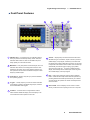
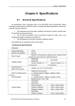
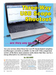
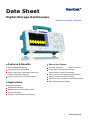
Date Sheet
Digital Storage Oscilloscope
DSO5202P DSO5102P DSO5072P
Features & Benefits
Ease-of-Use Feature
200/100/70MHz Bandwidths
Five math functions, +, -, *, /, and FFT functions.
1GSa/s Real Time Sample Rate
32 automatic measurements and track
Trigger mode: Edge, Pulse Width, Video, Slop,
measurement via cursor automatically.
Overtime, Alternative trigger etc.
Large (7.0-inch) color display,WVGA(800x480)
Provides software for PC real-time analysis
Support U disk and local files storage.
Pass/Fail Function enables to output testing results
Applications
Built in Bode diagram Assistant.
Design and Debug
Education and training
Manufacturing Test and Quality Control
Service and Repair
Electronic Circuit Designing and Testing.
1
www.hantek.com
Digital Storage Oscilloscope ---- DSO5000P Series
FFT
Autoset
Troubleshooting
If the oscilloscope is no display of waveforms on the screen when the
oscilloscope is turned on, follow these steps:
Dual-window Mode (Full Screen)
Math: CH1+CH2
Performance You Need at a Price You Can Afford
The DSO5000B Series Digital Storage Oscilloscope provides you
I. Check the probe to assure its proper connection to the input BNC;
with affordable performance in a compact design. Packed with stan-
II. Check the channel switch (such as CH1, CH2 menu buttons) to
dard features-including USB connectivity, 32 automated measurem-
make sure it has been turned on;
III. Check the input signal to verify it has been connected to the probe
correctly;
IV. Affirm that all measured circuits have signals to output;
V. Turn up the magnitude for DC signals with large magnitude;
VI. In addition, you may press the Auto Measure button to perform an
automatic detection of signals at first.
ents, limit testing, data loading, and context-sensitive make the
instruments help you get more done in less time. Digital Precision for
Accurate Measurements With up to 200MHz bandwidth and 1GS/s
maximum sample rate, no other digital storage oscilloscope offers as
much bandwidth and sample rate for the price. Hantek provides realtime sampling with a minimum of 10X oversampling on all channels,
all the time to accurately capture your signals.
Designed to Make Your Work Easy
The DSO Series oscilloscopes are designed with the ease of use and
familiar operation you have come to expect from Hantek
Help When You Need It, Where You Need It
The built-in Help menu provides you with important information on
Easy PC Connectivity
Easily capture, save, and analyze measurements results by connecting to your PC with the rear-panel USB device port. Simply pull
screen images and waveform data into the stand-alone desktop
application.
your oscilloscope’s features and functions. Help is provided in the
same languages as the user interface.
2
www.hantek.com
Digital Storage Oscilloscope ---- DSO5000P Series
Characteristics
Acquisition
Sample Rate
Acquisition Modes
Normal
Peak Detect
Average
Inputs
Input Coupling
Input Impendance
Probe Attenuation
Supported Probe
Attenuation Factor
Max. Input Voltage
Horizontal
Sample Rate Range
Waveform Interpolation
Record Length
SEC/DIV Range
Real-Time Sample: 1GS/s;
Equivalent Sample: 25GS/s
Normal data only
High-frequency and randon glith capture
Wavefom Average, selectable 4,8,16,32,64,128
AC, DC, GND
1MΩ±2% ‖20pF±3pF
1X, 10X
1X, 10X, 100X, 1000X
CAT I and CAT II: 300VRMS (10×); Installation Category III: 150VRMS (1×);
Installation Category II: derate at 20dB/decade above 100kHz to 13V peak AC at 3MHz and above.
For non-sinusoidal waveforms, peak value must be less than 450V.
Excursion above 300V should be of less than 100ms duration.
RMS signal level including all DC components removed through AC coupling must be limited
to 300V. If these values are exceeded, damage to the oscilloscope may occur.
500MS/s--1GS/s
(sin x)/x
24K
2ns/div to 40s/div, in a 2, 4, 8 sequence, DSO5202P
4ns/div to 40s/div, in a 2, 4, 8 sequence, DSO5102P/DSO5072P
Sample Rate and
Delay Time Accuracy
±50ppm(at over any ≥1ms time interval)
Position Range
DSO5202P:
2ns/div to 10ns/div; (-4div x s/div) to 20ms;
DSO5102P/DSO5072P:
20ns/div to 80us/div; (-8div x s/div) to 40ms;
200us/div to 40s/div; (-8div x s/div) to 400s;
Delta Time Measurement
Accuracy (Full Bandwidth)
Single-shot, Normal mode:± (1 sample interval +100ppm × reading + 0.6ns);
>16 averages:± (1 sample interval + 100ppm × reading + 0.4ns);
Sample interval = s/div ÷ 200
Vertical
Vertical Resolution
Volts/Div Range
Position Range
Bandwidth
Rise time at BNC(typical)
Analog Bandwidth in
Normal and Average Modes
at BNC or with probe,
DC Coupled
Math
FFT
Bandwidth Limit
8-bit resolution, all channel sampled simultaneously
2mV/div~10V/div
2mV/div to 200mV/div; ±2V;
200mV/div to 5V/div; ±50V
DSO5202P: 200MHz;
DSO5102P: 100MHz;
DSO5072P: 60MHz;
DSO5202P: 1.8ns;
DSO5102P: 3.5ns;
DSO5072P: 5ns;
2mV/div to 20mV/div, ±400mV;
50mV/div to 200mV/div, ±2V;
500mV/div to 2V/div, ±40V;
5V/div, ±50V
+, -, *, /, FFT
Windows: Hanning、Flatop、Rectamgular、Bartlett、Blackman;
1024 sample point;
20MHz
3
www.hantek.com
Digital Storage Oscilloscope ---- DSO5000P Series
Low Frequency Response (-3db)
DC Gain Accuracy
DC Measurement Accuracy,
Average Acquisition Mode
≤10Hz at BNC
±3% for Normal or Average acquisition mode, 5V/div to 10mV/div;
±4% for Normal or Average acquisition mode, 5mV/div to 2mV/div.
When vertical displacement is zero, and N ≥16:± (3% × reading + 0.1div + 1mV) only
10mV/div or greater is selected; When vertical displacement is not zero, and
N≥16: ± [3% × (reading + vertical position) + 1% of vertical position + 0.2div]; Add 2mV for
settings from 2mV/div to 200mV/div; add 50mV for settings from 200mV/div to 5V/div
Volts Measurement Repeatability,
Average Acquisition Mode
Trigger
Delta volts between any two averages of ≥16 waveforms acquired under same setup and
ambient conditions
Trigger Types
Trigger Source
Trigger Modes
Coupling Type
Edge, Video, Pulse, Slope, Over time, Alternative
CH1, CH2, EXT, EXT/5, AC Line
Auto, Normal
DC, AC, Noise Reject, HF Reject, LF Reject
DC(CH1,CH2):
1div from DC to 10MHz;1.5div from 10MHz to 100MHz; 2div from 100MHz to 200MHz;
DC(EXT):
200mV from DC to 100MHz; 350mV from 100MHz to 200MHz;
DC(EXT/5):
1V from DC to 100MHz;1.75V from 100MHz to 200MHz;
AC:
Attenuates signals below 10Hz
HF Reject:
Attenuates signals above 80kHz
LF Reject:
Same as the DC-coupled limits for frequencies above 150KHz;
Attenuates signals below 150KHz
CH1/CH2: ±8 divisions from center of screen;
EXT: ±1.2V;
EXT/5:±6V
Trigger Sensitivity
(Edge Trigger Type)
Trigger Level Range
Trigger Level Accuracy(typical)
Accuracy is for signals having
rise and fall times ≥20ns
Set Level to 50%(typical)
Trigger Holdoff range
CH1/CH2: 0.2div × volts/div within ±4 divisions from center of screen;
EXT: ± (6% of setting + 40mV);
EXT/5: ± (6% of setting + 200mV);
Operates with input signals ≥50Hz
100ns-10s
Video Trigger
Video Trigger Type
Signal Formats and Field Rates
Holdoff Range
Pulse Width Trigger
Pulse Width Trigger Mode
Pulse Width Trigger Point
Pulse Width Range
Overtime Trigger
Over Time Mode
Time Range
CH1, CH2: Peak-to-peak amplitude of 2 divisions;
EXT: 400mV;
EXT/5: 2V
Supports NTSC, PAL and SECAM broadcast systems for any field or any line
Line range: 1-525(NTSC), 1-625(PAL/SECAM)
100ns ~ 10s
Trigger when (< , >, = , or ≠); Positive pulse or Negative pulse
Equal: The oscilloscope triggers when the trailing edge of the pulse crosses the trigger level.
Not Equal: If the pulse is narrower than the specified width, the trigger point is the trailing edge.
Otherwise, the oscilloscope triggers when a pulse continues longer than the time specified as
the Pulse Width.
Less than: The trigger point is the trailing edge.
Greater than (also called overtime trigger): The oscilloscope triggers when a pulse continues
longer than the time specified as the Pulse Width
20ns ~ 10s
Rising edge or Falling edge
20ns ~ 10s
4
www.hantek.com
Digital Storage Oscilloscope ---- DSO5000P Series
Slope Trigger
Slope Trigger Mode
Slope Trigger Point
Time Range
Alternative Trigger
Trigger on CH1
Trigger on CH2
Trigger Frequency Counter
Readout Resolution
Accuracy (typical)
Frequency Range
Signal Source
Trigger when (< , > , = , or ≠ ); Positive slope or Negative slope
Equal: The oscilloscope triggers when the waveform slope is equal to the set slope.
Not Equal: The oscilloscope triggers when the waveform slope is not equal to the set slope.
Less than: The oscilloscope triggers when the waveform slope is less than the set slope.
Greater than: The oscilloscope triggers when the waveform slope is greater than the set slope.
20ns ~ 10s
Internal Trigger: Edge, Pulse Width, Video, Slope
Internal Trigger: Edge, Pulse Width, Video, Slope
6 digits
±30ppm (including all frequency reference errors and ±1 count errors)
AC coupled, from 4Hz minimum to rated bandwidth
Pulse Width or Edge Trigger modes: all available trigger sources;
The Frequency Counter measures trigger source at all times, including when the oscilloscope
acquisition pauses due to changes in the run status, or acquisition of a single shot event has
completed.
Pulse Width Trigger mode: The oscilloscope counts pulses of significant magnitude inside the 1s
measurement window that qualify as triggerable events, such as narrow pulses in a PWM pulse
train if set to < mode and the width is set to a relatively small time.
Edge Trigger mode: The oscilloscope counts all edges of sufficient magnitude and correct polarity.
Video Trigger mode: The Frequency Counter does not work.
Measurement
Cursor Measurement
Auto Measuerment
Manual: Voltage difference between cursors: △V;
Time difference between cursors: △T;
Reciprocal of △T in Hertz (1/ΔT);
Tracing: The voltage and time at a waveform point
Frequency, Period, Mean, Pk-Pk, Cycli RMS, Minimum, Maximum, Rise time, Fall Time,
+Pulse Width, -Pulse Width, Delay1-2Rise, Delay1-2Fall, +Duty, -Duty, Vbase, Vtop, Vmid,
Vamp, Overshoot, Preshoot, Preiod Mean, Preiod RMS, FOVShoot, RPREShoot, BWIDTH,
FRF, FFR, LRR, LRF, LFR, LFF
Display
Display Type
Display Resolution
Display Contrast
Probe Compensator Output
Output Voltage (typical)
Frequency(typical)
Power Supply
Supply Voltage
Power Consumption
Fuse
Environmental
Temperature
Cooling Method
Humidity
Altitude
7 inch 64K color TFT (diagonal liquid crystal)
800 horizontal by 480 vertical pixels
Adjustable (16 gears) with the progress bar
About 5Vpp into ≥1MΩ load
1KHz
100-120VACRMS(±10%), 45Hz to 440Hz, CATⅡ
120-240VACRMS(±10%), 45Hz to 66Hz, CATⅡ
<30W
2A, T rating, 250V
Operating: 32℉ to 122℉ (0℃ to 50℃);
Nonoperating: -40℉ to 159.8℉ (-40℃ to +71℃)
Convection
+104℉ or below (+40℃ or below): ≤90% relative humidity;
106℉ to 122℉ (+41℃ to 50℃): ≤60% relative humidity
Operating: Below 3,000m (10,000 feet);
Nonoperaring: Below 15,000m(50,000 feet)
Mechanical
Size
Weight
Packing: Length 385mm; Width 200mm; Height 245mm
Without Packing: Length 313mm; Width 108mm; Height 142mm
2.08KG(without Packing; 3.5KG(with Packing)
5
www.hantek.com
Digital Storage Oscilloscope ---- DSO5000P Series
Font Panel Features
5
7
6
8
4
3
1
1
USB Host Port -- Conveniently use your USB flash drive to
store your personal oscilloscope setups, screen shots,and
waveform data of later use, Also ues the USB host port to
easily update your instrument firmware.
2
Math Menu -- Easy and precise On-board Analysis, FFT and
waveform add, subtract, and multiply math functions come
standard on all models. FFT function displays frequency domain spectrums for fast harmonic distortion analysis or other
frequency based analysis.
3
Probe Check -- Quickly verity that your probe is calibrated
and operating properly
4
Triggers -- Quickly capture your event of interest with advanced triggers including Pulse Width, Edge, slope, Overtime
and line selectable video triggers.
5
2
6
Autoset -- Simplify setup with smart Autoset function which
identifies the type of waveform, asjusts controls to produce a
usable display of input signal, and allows you to select how
the waveform should be presented.This function can be used
to adjust the horizontal and vertical scales of the oscilloscope
automatically and set the trigger coupling, type, position,
slope, level and mode, etc., to acquire a stable waveform
display. Automatically set the oscilloscope controls to generate a usable display of the input signals.
7
Help -- Help system with topics covering all of its features.
Built in context-sensitive help further eases the operation by
providing indexed and linked topics that allow you to selectively learn about the operation of various oscilloscope features and functions.
8
Save to USB -- Save all displays on the screen to a USB
device, just like the screen capturing function of a computer.
F7 Button -- Push this button in single-window mode to
switch between dotted line display and cross display. Push
it in dual-window mode to perform auto cruise.
6
www.hantek.com
Digital Storage Oscilloscope ---- DSO5000P Series
Rear Panel Features
10
9
9 USB Device Port Combined with PC -- Easily communicate
with other instruments, peripherals or system via usb. The
USB port allows you full programmable controls for automated
measurements and remote display and archiving.
10 Integrated Handle -- Easily carry your light instruments
from a place to another.
Standard Accessories
Probe
Power Cord
Warranty Card
USB Line
CD
X1, X10 two passive probes. The passive probes have a 6MHz bandwidth (rated 100Vrms CAT III)
when the switch is in the X1 position, and a maximum bandwidth (rated 300Vrms CAT II) when the
switch is in the X10 position. Each probe consists of all necessary fittings.
A power cord special for this product. In addition to the power cord shipped with your instrument,
you may purchase another one certified for the country of use.
A warranty card. When there appears something wrong with the product, it can be returned for
repair under warranty.
A USB A-B line, used to connect external devices with USB-B interface like a printer or to
establish communications between PC and the oscilloscope.
A software installation CD. It contains the user manual of DSO5000B(MV), giving particular
descriptions on the DSO5000B(MV) series oscilloscopes.
Qingdao Hantek Electronic Co., Ltd
7
www.hantek.com