1
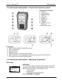
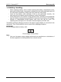
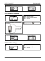
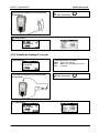
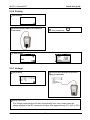
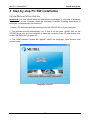
GammaPAT MI 3311 Short instructions Ver. 1.3, Code no. 20 751 626 Distributor: Manufacturer: METREL d.d. Ljubljanska cesta 77 1354 Horjul Slovenia E-mail: [email protected] http://www.metrel.si © 2010 METREL Mark on your equipment certifies that this equipment meets the requirements of the EU (European Union) concerning safety and electromagnetic compatibility regulations No part of this publication may be reproduced or utilized in any form or by any means without permission in writing from METREL. 2 MI 3311 GammaPAT Table of contents Table of contents 1 Start-up guide .........................................................................................................4 1.1 Safety and operational considerations ..............................................................4 1.2 Instrument description - Front and connector panel ..........................................5 1.3 Instrument description - Meaning of symbols ....................................................5 1.4 Battery handling ................................................................................................8 1.5 Warranty & Repairs ...........................................................................................9 1.6 Contact Metrel UK ...........................................................................................10 2 Quick-test guide ...................................................................................................11 2.1 Instrument test modes .....................................................................................11 2.2 Carrying out a Simple test ...............................................................................11 2.3 Carrying out a Shortcut test sequence ............................................................12 2.4 Carrying out a Single test ................................................................................12 2.5 Measurements.................................................................................................13 2.5.1 Earth Continuity........................................................................................13 2.5.2 Insulation resistance.................................................................................13 2.5.3 Insulation-P resistance .............................................................................14 2.5.4 Substitute leakage....................................................................................14 2.5.5 Substitute leakage-P current ....................................................................15 2.5.6 Polarity .....................................................................................................16 2.5.7 Voltage .....................................................................................................16 3 Step by step PC SW installation..........................................................................17 Appendix A – Simple test codes (UK)........................................................................20 Appendix B – Autotest shortcut codes (UK) .............................................................21 3 MI 3311 GammaPAT Start-up guide 1 Start-up guide 1.1 Safety and operational considerations Ì Ì Ì Ì Ì Ì Ì Ì Ì Ì Ì Ì Ì Ì Ì Ì Warning on the instrument means »Read the Instruction manual with special care to safety operation«. The symbol requires an action! Read this instruction manual carefully, otherwise use of the instrument may be dangerous for the operator, for the instrument or for the equipment under test! If the test equipment is used in manner not specified in this instruction manual the protection provided by the equipment may be impaired! Do not use the instrument and accessories if any damage is noticed! The Instrument should not to be used for measurements while charging. Consider all generally known precautions in order to avoid risk of electric shock while dealing with hazardous voltages! Appliances MUST be fully disconnected from the mains supply before it is connected to the MI3311 GammaPAT in order to perform a PAT test. Do not touch any test leads/terminals while the appliance is connected to the MI3311 GammaPAT. Use only standard or optional test accessories, supplied by your distributor! Instrument servicing and adjustment is only allowed to be carried out by competent authorized personnel! Hazardous voltages can exist inside the instrument. Disconnect all test leads, remove the power supply cable and switch off the instrument before opening the battery compartment. Instrument contains rechargeable NiCd or NiMh battery cells. The cells should only be replaced with the same type as defined on the battery placement label or in this manual. Do not use standard alkaline battery cells while power supply adapter is connected, otherwise they may explode! If a test code with an earth bond test current higher than 200 mA is selected (manually or with barcode reader) the GammaPAT instrument will automatically perform the Earth continuity test with a 200 mA test current. Other test parameters remain unchanged. The operator must be competent to decide if performing the test with a 200 mA current is acceptable! The Substitute leakage current / Substitute leakage-P tests can be carried out as an alternative for the Leakage and Touch leakage tests if there are no mains supply dependent switches inside the equipment. The operator must be competent to decide if performing the substitute leakage current test is applicable! If a test code with a Leakage current is selected (manually or with barcode reader) the GammaPAT instrument will automatically perform a Substitute leakage test. Other test parameters remain unchanged. The operator must be competent to decide if performing the Substitute leakage test is acceptable! If a test code with a Touch leakage current is selected (manually or with barcode reader) the GammaPAT instrument will automatically perform a Substitute leakage-P test. Other test parameters remain unchanged. The operator must be competent to decide if performing the Substitute leakage-P test is acceptable! 4 MI 3311 GammaPAT Start-up guide 1.2 Instrument description - Front and connector panel Instrument description 1. Display 2. FAIL indicator 3. PASS indicator 4. TEST key 5. UP key 6. DOWN key 7. MEM key 8. TAB key 9. ON/OFF (2 sec), ESC key 10. Mains test socket Connectors 1. S/EB1 Probe and Earth continuity terminal 2. IEC / Voltage input 3. Protection cover 4. Charger socket 5. USB connector for communication with PC 6. PS/2 connector for communication with barcode scanner and PC (RS-232) 7. PE terminal (for checking S/EB test lead) 1.3 Instrument description - Meaning of symbols Warnings WARNING! An excessively high resistance was measured in the fuse pre-test. This indication means that the device under test has extremely low power consumption or it is: Ì not connected; Ì switched off; Ì contains a fuse that has blown. Select PROCEED or CANCEL. 5 MI 3311 GammaPAT Start-up guide WARNING! Voltage on mains test socket between LN - PE terminals is higher than approximately 20 V (AC or DC)! Disconnect the device under test (DUT) from the instrument immediately and determine why an external voltage was detected! WARNING! Current on test probe (S/EB1 - PE) is higher than approximately 10mA (AC or DC)! Disconnect the test probe from the device under test (DUT) and determine why an external current was detected! WARNING! The Simple test memory has reached the limit of 50 sequences. WARNING! The internal memory is full! WARNING! The calibration period will expire in less than 1 month. The instrument counts down the days. WARNING! The calibration period has expired. Recalibrate the instrument! WARNING! A high insulation test voltage will be present on the output of the instrument! WARNING! A high insulation test voltage is present on the output of the instrument. 6 MI 3311 GammaPAT Start-up guide Symbols Measurement in progress. Test result can be saved. Connect the test lead to the S/EB1 test socket. Flex the mains cable of appliance during the test. Check that the device under test is switched on (to ensure that the complete circuit is tested). Connect the cord to be tested to the IEC test terminal. The results of the Substitute leakage current / Substitute leakage–P tests are calculated based on a 110V power supply. Test passed. Test failed. Battery and charging indications Battery capacity indication. Low battery. Battery is too weak to guarantee correct result. Replace or recharge the battery cells. Recharging in progress (if external charger is connected). 7 MI 3311 GammaPAT Start-up guide 1.4 Battery handling Ì Ì Ì Ì When replacing battery cells or before opening the battery compartment cover, disconnect all test leads / accessories connected to the instrument and switch off the instrument. Hazardous voltage can exist inside the instrument! Insert all the battery cells correctly! If this is not performed correctly, the instrument will not operate and the batteries could be discharged. If the instrument is not used for a long period of time, remove all of the batteries from the battery compartment to protect the instrument from battery acid leakage. Alkaline or rechargeable Ni-MH battery cells (size AA) can be used. The operating hours are given for cells with a nominal capacity of 2100 mAh. The battery will begin charging as soon as the power supply adapter is connected to the instrument. The in-built protection circuit controls the charging procedure... WARNING! Do not recharge alkaline battery cells! Power supply socket polarity Note: Ì Only use the power supply adapter delivered from manufacturer or distributor of the test equipment to avoid possible fire or electric shock! 8 MI 3311 GammaPAT Start-up guide 1.5 Warranty & Repairs Metrel UK’s instruments have a three year warranty against defects in materials or workmanship. Accessories and other supplementary products have a one year warranty against defects in materials or workmanship. Any potentially defective items should be returned to Metrel accompanied by information regarding the faults that was incurred. It is recommended that any defective equipment is sent back to Metrel via the wholesaler from which the product was purchased. All defective products will be replaced or repaired within policy period. For these items, a full refund will only be issued if a sufficient replacement is not available. Any shipping / return-shipping costs are not refundable. Metrel UK shall not be held liable for any loss or damage resulting from the use or performance of the products. In no event shall Metrel UK be liable to the customer or its customers for any special, indirect, incidental, exemplary or punitive damages resulting from loss of use, interruption of business or loss of profits, even if Metrel UK has been advised of the possibility of such damages. If the customer’s unit is out of warranty but needs repairs a quote for repair will be provided via the wholesaler through which the instrument was sent in. Notes: Ì Any unauthorized repair or calibration of the instrument will infringe the product’s warranty. Ì All sales are subject to Metrel UK’s Standard Terms and Conditions, a full copy of which is available Metrel UK’s office. Metrel UK reserves the right to change the conditions at any time. Any typographical, clerical or other error or omission in any sales literature, quotation, price list, acceptance of offer, invoice or other documentation or information issued by Metrel UK shall be subject to correction without any liability on the part of the customer. Ì Specifications and designs of goods are subject to change by Metrel UK at any time without notice to the customer. Metrel UK reserves the right to make any changes in the specification of goods which are required to conform with any applicable statutory or EC requirements or, where goods are to be supplied to Metrel UK’s specification, which do not materially affect their quality or performance. Ì If a condition was found to be invalid or void it would not affect the overall validity of the remainder of the conditions; Ì Metrel UK are excluded from liability for any delays or failure to comply, where the reason is beyond Metrel UK’s control; Ì No order which has been accepted by Metrel UK may be cancelled by the customer except with the agreement in writing of Metrel UK and on terms that the customer shall indemnify Metrel UK in full against all loss (including loss of profit), costs (including the cost of all labour and materials used), damages, charges and expenses incurred by Metrel UK as a result of cancellation. The minimum charge for such cancellation will be 25 % of the total value of the goods ordered. 9 MI 3311 GammaPAT Start-up guide 1.6 Contact Metrel UK Metrel UK Unit 1, Hopton House, Ripley Drive Normanton Industrial Estate Normanton, West Yorkshire WF6 1QT Tel.:+44/ (0) 1924 24 50 00 Fax: +44/(0) 1924 24 50 07 E-mail: [email protected] Web: www.metrel.co.uk Update your meter Metrel offers a service of updating your software of firmware to the latest developments. Register on www.metrel.co.uk to receive updates of PC SW and firmware of the meters. Calibrate your Meter Metrel offers a calibration service of all Metrel equipment. Contact Metrel UK on 01924 245000 and ask for the calibrations department. Repair Metrel offers a repair service of all Metrel equipment. Contact Metrel UK on 01924 245000 and ask for the repairs department. Ask a technical question Metrel offers a Technical Advice Line every Mon-Thu from 8:00 a.m. till 5.00 p.m. and Fridays from 8:00 a.m. till 4 p.m.. Get training on Metrel meters Metrel offers training on site or at the office subject to a charge. 10 MI 3311 GammaPAT Quick-test guide 2 Quick-test guide 2.1 Instrument test modes Instrument has three main operation modes. Ì Ì Ì Ì Ì <SIMPLE TEST> simple pre-programmed sequences; test sequences can be user customized. <SHORTCUT MENU> code-based test sequences, suitable for working with barcodes. <SINGLE TEST> individual tests. <HELP> help screens. <SETUP> menu for setup of the instrument. 2.2 Carrying out a Simple test 1 3 2 Set function In Main menu select SIMPLE TEST. Carry out the simple test sequence Press TEST to start test sequence Certain tests will pre-select limits but will allow the user to adjust (if required). 4 11 Select the appropriate test sequence View results After test sequence is finished Autotest Result screen and an overall PASS/FAIL indication is displayed. MI 3311 GammaPAT Quick-test guide 2.3 Carrying out a Shortcut test sequence 1 Set function In Main menu select SHORTCUT MENU. 2 3 Carry out Shortcut autotest sequence Press TEST to Start autotest Certain tests will preselect limits but will allow the user to adjust (if required). 4 Set appliance type and protective measures Use the TAB and UP and DOWN arrows to set the appliance type, class etc or select (scan) the appropriate code. View results After Shortcut test sequence is finished. Autotest Result screen and an overall PASS/FAIL indication is displayed. 2.4 Carrying out a Single test 1 2 Set function In Main menu select SINGLE TEST. 3 Carry out measurement or inspection Press TEST to start single test Certain tests will allow limits to be set (if required). 4 12 Select the appropriate Single test View results After test is finished Result screen and PASS/FAIL indication is displayed MI 3311 GammaPAT Quick-test guide 2.5 Measurements 2.5.1 Earth Continuity 1 2 Set function Set parameters and limits Output ... Size of test current Limit .........Maximum earth continuity resistance Time .........Test time. 3 Connect the appliance to the instrument (as illustrated) 5 4 TEST Carry out the test View results 2.5.2 Insulation resistance 1 2 Set function Set parameters and limits Output....Size of test voltage Limit ........ Minimum insulation resistance Time ......... Test time. 3 Connect the appliance to the Instrument (as illustrated) 4 13 TEST Carry out the test MI 3311 GammaPAT 5 Quick-test guide View results 2.5.3 Insulation-P resistance 1 2 Set function Set parameters and limits Output....Size of test voltage Limit ........ Minimum insulation resistance Time ......... Test time. 3 Connect the appliance to the Instrument (as illustrated) 5 4 TEST Carry out the test View results 2.5.4 Substitute leakage 1 2 Set function Set parameters and limits Output....Size of test voltage Limit ........ Maximum leakage current Time ......... Test time. 14 MI 3311 GammaPAT Quick-test guide 3 Connect the appliance to the Instrument (as illustrated) 5 4 TEST Carry out the test View results 2.5.5 Substitute leakage-P current 1 2 Set function Set parameters and limits Output ....Size of test voltage Limit ......... Maximum touch leakage current Time ......... Test time. 3 Connect the appliance to the Instrument (as illustrated) 5 4 View results 15 TEST Carry out the test MI 3311 GammaPAT Quick-test guide 2.5.6 Polarity 1 Set function 2 Connect the IEC cable to the instrument (as illustrated) 4 3 TEST Carry out the test View results 2.5.7 Voltage 1 3 2 Set function Connect the Instrument to the mains supply (as illustrated) Carry out the test The voltage measurement will start automatically from every mode when the voltage applied to the IEC connector is higher than approximately 50 V (AC or DC)! 16 MI 3311 GammaPAT Quick-test guide 3 Step by step PC SW installation PATLink PRO and PATLink PRO Plus Important: The user should have full administrative privileges, in the case of Windows 7 is installed on you computer. Read the document in section Installing instructions Æ privileges troubleshooting on windows 7 1. Insert a CD delivered with the instrument into the CD/DVD drive of your computer. 2. The software should automatically run. If this is not the case, double click on the CD/DVD drive icon on your computer to open the contents of the CD and double click on the “METREL.exe” program file. 3. The initial welcome screen will appear, select the language, area location and product name. Language selection 17 MI 3311 GammaPAT Quick-test guide Area selection Product name selection 4. To install the software, Select PATLink PRO in the next screen 18 MI 3311 GammaPAT Quick-test guide Product section 5. The installation of the software will now begin, on the welcome screen Select »Next« and follow the setup instructions. 6. After completing the installation, confirm finishing the installation leave the check box ticked to automatically start the program (a shortcut is automatically placed on the desktop and in the start menu for future software initiations). 7. To start PATLink PRO software, click the shortcut on the desktop or in the start menu Help files are available on the software to guide you through the various sections of the software. 8. Select “Installing USB”. Read carefully Installing USB instruction manual available on CD and follow the instruction on how to establish connection between instrument and PC and download the data. The USB drivers will be automatically installed on the windows 7 operating system. 19 MI 3311 GammaPAT Appendix A – Autotest shortcut codes (UK) Appendix A – Simple test codes (UK) Type Class Earth continuity Limit Out Insulation Limit Out S. Leakage Limit Polarity CLASS I CLASS II IEC CLASS I PC I II I 0.20 Ω 0.20 Ω 0.20 Ω 1.00 MΩ 2.00 MΩ 1.00 MΩ 1.00 MΩ 0.75 mA 0.25 mA 0.75 mA - 200 mA 200 mA 200 mA 500 V 500 V 500 V 250 V 20 9 - MI 3311 GammaPAT Appendix B – Autotest shortcut codes (UK) Appendix B – Autotest shortcut codes (UK) Autotests marked bold are available if SHORTCUT setup is set to BASIC. Type Class Fuse Cord Earth Bond Limit Out Insulation Limit Out S. Leakage Leakage Limit Limit T. Leakage Code Limit I I I I 3A 6A 10 A 13 A short short short short 0.10 Ω 0.10 Ω 0.10 Ω 0.10 Ω 10 A 10 A 25 A 25 A 1.00 MΩ 1.00 MΩ 1.00 MΩ 1.00 MΩ 500 V 500 V 500 V 500 V - 0.75 mA 0.75 mA 0.75 mA 0.75 mA - 001 002 003 004 I I I I 3A 6A 10 A 13 A short short short short 0.10 Ω 0.10 Ω 0.10 Ω 0.10 Ω 10 A 10 A 25 A 25 A 1.00 MΩ 1.00 MΩ 1.00 MΩ 1.00 MΩ 500 V 500 V 500 V 500 V - - - 005 006 007 008 I I I I 3A 6A 10 A 13 A midd midd midd midd 0.30 Ω 0.30 Ω 0.30 Ω 0.30 Ω 10 A 10 A 25 A 25 A 1.00 MΩ 1.00 MΩ 1.00 MΩ 1.00 MΩ 500 V 500 V 500 V 500 V - 0.75 mA 0.75 mA 0.75 mA 0.75 mA - 009 010 011 012 I I I I 3A 6A 10 A 13 A midd midd midd midd 0.30 Ω 0.30 Ω 0.30 Ω 0.30 Ω 10 A 10 A 25 A 25 A 1.00 MΩ 1.00 MΩ 1.00 MΩ 1.00 MΩ 500 V 500 V 500 V 500 V - - - 013 014 015 016 I I I I 3A 6A 10 A 13A long long long long 0.50 Ω 0.50 Ω 0.50 Ω 0.50 Ω 10 A 10 A 25 A 25 A 1.00 MΩ 1.00 MΩ 1.00 MΩ 1.00 MΩ 500 V 500 V 500 V 500 V - 0.75 mA 0.75 mA 0.75 mA 0.75 mA - 017 018 019 020 I I I I 3A 6A 10 A 13 A long long long long 0.50 Ω 0.50 Ω 0.50 Ω 0.50 Ω 10 A 10 A 25 A 25 A 1.00 MΩ 1.00 MΩ 1.00 MΩ 1.00 MΩ 500 V 500 V 500 V 500 V - - - 021 022 023 024 II II - - - - 2.00 MΩ 500 V 2.00 MΩ 500 V - 0.25 mA - - 025 026 Portable or Handheld 21 MI 3311 GammaPAT Type Appendix B – Autotest shortcut codes (UK) Class Fuse Cord Earth Bond Limit Out Insulation Limit Out S. Leakage Leakage Limit Limit T. Leakage Code Limit I I I I 3A 6A 10 A 13 A short short short short 0.10Ω 0.10 Ω 0.10 Ω 0.10 Ω 10 A 10 A 25 A 25 A - - - 0.75 mA 1.00 mA 1.50 mA 2.25 mA - 027 028 029 030 I I I I 3A 6A 10 A 13 A short short short short 0.10 Ω 0.10 Ω 0.10 Ω 0.10 Ω 10 A 10 A 25 A 25 A - - 0.75 mA 1.00 mA 1.50 mA 2.25 mA - - 031 032 033 034 II II - - - - 2.00 MΩ 500 V 2.00 MΩ 500 V - 0.25 mA - - 035 036 Class Fuse Cord Earth Bond Limit Out Insulation Limit Out S. Leakage Leakage Limit Limit T. Leakage Code Limit I - 1.00 MΩ 500 V 3.5 mA - - 037 I - 1.00 MΩ 500 V 3.5 mA - - 038 I - short 0.10 Ω 100 mA midd 0.30 Ω 100 mA long 0.50 Ω 100 mA 1.00 MΩ 500 V 3.5 mA - - 039 I - long 1.00 MΩ 250 V 3.5 mA - - 040 Class Fuse Cord Earth Bond Limit Out Insulation Limit Out S. Leakage Leakage Limit Limit T. Leakage Code Limit I I I I 3A 6A 10 A 13 A short short short short 0.10 Ω 0.10 Ω 0.10 Ω 0.10 Ω 10 A 10 A 25A 25 A 1.00 1.00 1.00 1.00 MΩ MΩ MΩ MΩ 500 V 500 V 500 V 500 V - 3.50 mA 3.50 mA 3.50 mA 3.50 mA - I I I I 3A 6A 10 A 13 A short short short short 0.10 Ω 0.10 Ω 0.10 Ω 0.10 Ω 10 A 10 A 25 A 25 A 1.00 1.00 1.00 1.00 MΩ MΩ MΩ MΩ 500 V 500 V 500 V 500 V - - - 045 046 047 048 I I I I 3A 6A 10 A 13 A midd midd midd midd 0.30 Ω 0.30 Ω 0.30 Ω 0.30 Ω 10 A 10 A 25 A 25 A 1.00 1.00 1.00 1.00 MΩ MΩ MΩ MΩ 500 V 500 V 500 V 500 V - 3.50 mA 3.50 mA 3.50 mA 3.50 mA - 049 050 051 052 I I I I 3A 6A 10 A 13 A midd midd midd midd 0.30 Ω 0.30 Ω 0.30 Ω 0.30 Ω 10 A 10 A 25 A 25 A 1.00 1.00 1.00 1.00 MΩ MΩ MΩ MΩ 500 V 500 V 500 V 500 V - - - 053 054 055 056 I I I I 3A 6A 10 A 13 A long long long long 0.50 Ω 0.50 Ω 0.50 Ω 0.50 Ω 10 A 10 A 25 A 25 A 1.00 1.00 1.00 1.00 MΩ MΩ MΩ MΩ 500 V 500 V 500 V 500 V - 3.50 mA 3.50 mA 3.50 mA 3.50 mA - 057 058 059 060 I I I I 3A 6A 10 A 13 A long long long long 0.50 Ω 0.50 Ω 0.50 Ω 0.50 Ω 10 A 10 A 25 A 25 A 1.00 1.00 1.00 1.00 MΩ MΩ MΩ MΩ 500 V 500 V 500 V 500 V - - - 061 062 063 064 Heating and Cooking Type IT equipment EN 60950 IT equipment EN 60950 – 250V Type 0.50 Ω 100 mA OTHER 22 041 042 043 044 MI 3311 GammaPAT II II - Appendix B – Autotest shortcut codes (UK) - - - 2.00 MΩ 500 V 2.00 MΩ 500 V - 0.25 mA - - 065 066 IEC leads Surge protected = OFF / RCD protected = OFF Length 0.5mm2 / 3A 0.75mm2 / 6 A 1 mm2/ 10 A 1.25mm2/ 13A 1.5mm2/ 15 A Earth Bond Limit Out Insulation Limit Out Polarity Code <=5 m 7.5 m 10 m 12 m 15 m 20 m 30 m 40 m 50 m 0.30 Ω 0.40 Ω 0.50 Ω 0.60 Ω 0.70 Ω 0.80 Ω 1.00 Ω 2.00 Ω 2.00 Ω 10 A 10 A 10 A 10 A 10 A 10 A 10 A 10 A 10 A 1.00 MΩ 1.00 MΩ 1.00 MΩ 1.00 MΩ 1.00 MΩ 1.00 MΩ 1.00 MΩ 1.00 MΩ 1.00 MΩ 500 V 500 V 500 V 500 V 500 V 500 V 500 V 500 V 500 V 9 9 9 9 9 9 9 9 9 067 068 069 070 071 072 073 074 075 <=5 m 7.5 m 10 m 12 m 15 m 20 m 30 m 40 m 50 m 0.20 Ω 0.30 Ω 0.40 Ω 0.40 Ω 0.50 Ω 0.60 Ω 0.90 Ω 1.00 Ω 1.00 Ω 10 A 10 A 10 A 10 A 10 A 10 A 10 A 10 A 10 A 1.00 MΩ 1.00 MΩ 1.00 MΩ 1.00 MΩ 1.00 MΩ 1.00 MΩ 1.00 MΩ 1.00 MΩ 1.00 MΩ 500 V 500 V 500 V 500 V 500 V 500 V 500 V 500 V 500 V 9 9 9 9 9 9 9 9 9 076 077 078 079 080 081 082 083 084 <=5 m 7.5 m 10 m 12 m 15 m 20 m 30 m 40 m 50 m 0.20 Ω 0.20 Ω 0.30 Ω 0.30 Ω 0.40 Ω 0.50 Ω 0.70 Ω 0.90 Ω 1.00 Ω 25 A 25 A 25 A 25 A 25 A 25 A 25 A 25 A 25 A 1.00 MΩ 1.00 MΩ 1.00 MΩ 1.00 MΩ 1.00 MΩ 1.00 MΩ 1.00 MΩ 1.00 MΩ 1.00 MΩ 500 V 500 V 500 V 500 V 500 V 500 V 500 V 500 V 500 V 9 9 9 9 9 9 9 9 9 085 086 087 088 089 090 091 092 093 <=5 m 7.5 m 10 m 12 m 0.20 Ω 0.20 Ω 0.30 Ω 0.30 Ω 25 A 25 A 25 A 25 A 1.00 MΩ 1.00 MΩ 1.00 MΩ 1.00 MΩ 500 V 500 V 500 V 500 V 9 9 9 9 094 095 096 097 <=5 m 7.5 m 10 m 12 m 15 m 0.20 Ω 0.20 Ω 0.20 Ω 0.30 Ω 0.30 Ω 25 A 25 A 25 A 25 A 25 A 1.00 MΩ 1.00 MΩ 1.00 MΩ 1.00 MΩ 1.00 MΩ 500 V 500 V 500 V 500 V 500 V 9 standard 9 standard 9 standard 9 standard 9 standard 103 104 105 106 107 <=5 m 7.5 m 10 m 12 m 15 m 20 m 30 m 40 m 50 m 0.20 Ω 0.20 Ω 0.20 Ω 0.30 Ω 0.30 Ω 0.40 Ω 0.50 Ω 0.60 Ω 0.80 Ω 25 A 25 A 25 A 25 A 25 A 25 A 25 A 25 A 25 A 1.00 MΩ 1.00 MΩ 1.00 MΩ 1.00 MΩ 1.00 MΩ 1.00 MΩ 1.00 MΩ 1.00 MΩ 1.00 MΩ 500 V 500 V 500 V 500 V 500 V 500 V 500 V 500 V 500 V 9 standard 9 standard 9 standard 9 standard 9 standard 9 standard 9 standard 9 standard 9 standard 112 113 114 115 116 117 118 119 120 UNKNOWN 23 MI 3311 GammaPAT Appendix B – Autotest shortcut codes (UK) IEC leads Surge protected = ON RCD protected ? = OFF Length 0.5mm2 / 3A 0.75mm2 / 6 A 1 mm2/ 10 A 1.25mm2/ 13A 1.5mm2/ 15 A Earth Bond Limit Out Insulation Limit Out Polarity Code <=5 m 7.5 m 10 m 12 m 15 m 20 m 30 m 40 m 50 m 0.30 Ω 0.40 Ω 0.50 Ω 0.60 Ω 0.70 Ω 0.80 Ω 1.00 Ω 2.00 Ω 2.00 Ω 10 A 10 A 10 A 10 A 10 A 10 A 10 A 10 A 10 A 1.00 MΩ 1.00 MΩ 1.00 MΩ 1.00 MΩ 1.00 MΩ 1.00 MΩ 1.00 MΩ 1.00 MΩ 1.00 MΩ 250 V 250 V 250 V 250 V 250 V 250 V 250 V 250 V 250 V 9 standard 9 standard 9 standard 9 standard 9 standard 9 standard 9 standard 9 standard 9 standard 167 168 169 170 171 172 173 174 175 <=5 m 7.5 m 10 m 12 m 15 m 20 m 30 m 40 m 50 m 0.20 Ω 0.30 Ω 0.40 Ω 0.40 Ω 0.50 Ω 0.60 Ω 0.90 Ω 1.00 Ω 1.00 Ω 10 A 10 A 10 A 10 A 10 A 10 A 10 A 10 A 10 A 1.00 MΩ 1.00 MΩ 1.00 MΩ 1.00 MΩ 1.00 MΩ 1.00 MΩ 1.00 MΩ 1.00 MΩ 1.00 MΩ 250 V 250 V 250 V 250 V 250 V 250 V 250 V 250 V 250 V 9 standard 9 standard 9 standard 9 standard 9 standard 9 standard 9 standard 9 standard 9 standard 176 177 178 179 180 181 182 183 184 <=5 m 7.5 m 10 m 12 m 15 m 20 m 30 m 40 m 50 m 0.20 Ω 0.20 Ω 0.30 Ω 0.30 Ω 0.40 Ω 0.50 Ω 0.70 Ω 0.90 Ω 1.00 Ω 25 A 25 A 25 A 25 A 25 A 25 A 25 A 25 A 25 A 1.00 MΩ 1.00 MΩ 1.00 MΩ 1.00 MΩ 1.00 MΩ 1.00 MΩ 1.00 MΩ 1.00 MΩ 1.00 MΩ 250 V 250 V 250 V 250 V 250 V 250 V 250 V 250 V 250 V 9 standard 9 standard 9 standard 9 standard 9 standard 9 standard 9 standard 9 standard 9 standard 185 186 187 188 189 190 191 192 193 <=5 m 7.5 m 10 m 12 m 0.20 Ω 0.20 Ω 0.30 Ω 0.30 Ω 25 A 25 A 25 A 25 A 1.00 MΩ 1.00 MΩ 1.00 MΩ 1.00 MΩ 250 V 250 V 250 V 250 V 9 standard 9 standard 9 standard 9 standard 194 195 196 197 <=5 m 7.5 m 10 m 12 m 15 m 0.20 Ω 0.20 Ω 0.20 Ω 0.30 Ω 0.30 Ω 25 A 25 A 25 A 25 A 25 A 1.00 MΩ 1.00 MΩ 1.00 MΩ 1.00 MΩ 1.00 MΩ 250 V 250 V 250 V 250 V 250 V 9 standard 9 standard 9 standard 9 standard 9 standard 203 204 205 206 207 <=5 m 7.5 m 10 m 12 m 15 m 20 m 30 m 40 m 50 m 0.20 Ω 0.20 Ω 0.20 Ω 0.30 Ω 0.30 Ω 0.40 Ω 0.50 Ω 0.60 Ω 0.80 Ω 25 A 25 A 25 A 25 A 25 A 25 A 25 A 25 A 25 A 1.00 MΩ 1.00 MΩ 1.00 MΩ 1.00 MΩ 1.00 MΩ 1.00 MΩ 1.00 MΩ 1.00 MΩ 1.00 MΩ 250 V 250 V 250 V 250 V 250 V 250 V 250 V 250 V 250 V 9 standard 9 standard 9 standard 9 standard 9 standard 9 standard 9 standard 9 standard 9 standard 212 213 214 215 216 217 218 219 220 UNKNOWN 24 MI 3311 GammaPAT Type Appendix B – Autotest shortcut codes (UK) Portable RCD Earth Bond Limit Out 0.10 Ω Type 25 A Leakage Limit 0.75 mA RCD 30mA Auto Polarity 9 active Code 400 Class III equipment Visual 9 Meaning of symbols used in autotest shortcut codes tables: 9 test/measurement enabled, - test/measurement disabld 25 Code 500