1
SYncomm 5.5
User’s Manual
Synel Industries Ltd.
Manual 07/02/05, Catalog no.660000 Part no. (SYncomm-223-043)
This document has been prepared for SYncomm ver. 5.5.
Copyright © 1995-2004 Synel Industries Ltd. All rights reserved.
Reproduction or use, without express permission of editorial or pictorial
content, in any manner is prohibited. No patent liability is assumed with
respect to the use of the information contained herein. While every
precaution has been taken in the preparation of this manual, Synel
Industries Ltd. assumes no responsibility for errors or omissions. Neither
is any liability assumed for damages resulting from the use of the
information contained herein.
All trade names referenced herein are either trademarks or registered
trademarks of their respective companies.
Synel Industries Ltd.
SYncomm 5.5
Table of contents
Table of contents
Introduction.................................................................................... 1
1.1.
1.2
SYncomm modules.....................................................................2
System Requirements..................................................................4
Installation...................................................................................... 5
2.1.
2.1.
Install software............................................................................5
Multi-user installation.................................................................5
Getting Started ............................................................................... 7
3.1.
3.2.
3.2.1
3.2.2
3.2.3
Screen Layout .............................................................................7
Setting-up Your SYncomm System..........................................12
Communication setup ...............................................................12
Activities ...................................................................................13
Terminal type activity chart ......................................................16
Communication setup.................................................................. 19
4.1.
4.2.
4.2.1
4.2.2
4.3.
4.4.
4.5.
4.6.
4.7.
Protocols ...................................................................................19
Terminals ..................................................................................21
Navigating the terminal module................................................22
Locating Net Terminals ............................................................24
Groups.......................................................................................25
Modems ....................................................................................26
USB...........................................................................................27
Automation ...............................................................................28
Security Group ..........................................................................30
Set-up ......................................................................................... 31
5.1.
5.1.1
5.1.2
5.1.3
5.1.4
5.1.5
5.1.6
5.1.7
5.1.8
5.2.
5.2.1
5.2.2
5.3.
5.3.1
Global........................................................................................31
Default definitions.....................................................................31
Activities ...................................................................................32
Edit Program Configuration......................................................34
Fingerprint.................................................................................35
Multi-users ................................................................................35
Default Locations......................................................................36
Permissions ...............................................................................36
E-mail Configuration ................................................................37
Sets............................................................................................38
Default Set.................................................................................38
Configuration Sets.....................................................................39
Communication Program ..........................................................39
Phantom Configuration .............................................................39
Synel Industries Ltd.
i
Table of contents
5.3.2
5.4.
5.5.
5.5.1
5.5.2
5.5.3
5.5.4
SYncomm 5.5
SYNDLL Configuration............................................................40
Backup Configuration ...............................................................40
Program Configuration .............................................................40
Activity screen...........................................................................40
Terminals...................................................................................43
Default Modem .........................................................................44
Printer ........................................................................................44
Edit program................................................................................ 47
6.1.
6.2.
6.3
6.3.1
6.3.2
6.3.3
6.3.4
6.3.5
6.3.6
6.3.7
6.3.8
6.3.9
6.3.10
Synel terminals..........................................................................47
Linear terminals ........................................................................48
SY-780/A Programming ...........................................................50
Messages ...................................................................................51
Input ..........................................................................................51
Valid..........................................................................................52
Not Valid...................................................................................53
Employees .................................................................................53
Printer Notes .............................................................................55
Test............................................................................................56
Transaction................................................................................61
General ......................................................................................62
Weekly ......................................................................................63
Appendix A: Maintenance .......................................................... 65
1.
2.
3.
3.1
3.2
3.3
3.4
3.5
3.6
3.7
3.8
4.
4.1
4.2
4.3
4.4
ii
Back-up .....................................................................................65
Restore ......................................................................................65
Advanced ..................................................................................65
Re-index ....................................................................................65
Build indexes.............................................................................65
Return All Program Settings to Default ....................................65
Upgrading firmware - SY780 terminals....................................65
Formatting memory...................................................................66
View SYncomm database .........................................................66
Report Builder ...........................................................................66
Create translation files...............................................................67
Utilities......................................................................................67
WinJTrans .................................................................................67
Check RDY ...............................................................................68
Convert Templates ....................................................................68
Update Day Light Saving Time ................................................69
Synel Industries Ltd.
SYncomm 5.5
Table of contents
Fingerprint ................................................................................... 73
Appendix B: SY7xx/SY4xx-RDY Format.................................. 81
1.
2.
2.1
3.
3.1
3.2
3.3
3.3
Note:
4.
5.
6.
6.
General......................................................................................81
Header structure ........................................................................82
Table A – Header structure .......................................................82
System tables ............................................................................83
Table B- Header of system tables .............................................83
Task Scheduler table .................................................................84
Task Scheduler record format...................................................84
Data field structure for function key operation:........................84
Data field structure for Output operations: ...............................85
Data field structure for Modem operations:..............................86
System parameters table record format.....................................87
Day Light Saving Time parameter structure.............................88
Setting the daylight savings time control..................................88
TRS record structure .................................................................90
TRP record structure .................................................................90
FNT record structure.................................................................90
Record structure of MPL ..........................................................93
Display @-Sequences formats..................................................94
Printer @-Sequences formats ...................................................95
Algorithm for Synel’s numeric fields .......................................96
Multi-drop ID algorithm ...........................................................96
HighByte + LowByte algorithm ...............................................96
HighByte + MiddleByte + LowByte algorithm*......................96
Synel Industries Ltd.
iii
SYncomm version 5.5
Introduction
Chapter 1 - Introduction
SYncomm is a software that manages Synel terminals' environmental
communication activities.
The spectrum of SYncomm’s capacities is wide, it can manage
communication between terminals and host using net and local protocols.
SYncomm’s multi-scale activities are outlined below:
•
Grants full support for SY-7XX terminal programming, other
terminals are supported using data editing.
•
For SY-400A/760/780A terminals the following can be implemented
(only under Terminal type SY780):
- Remote Upgrading Firmware.
- Memory Formatting from the software (not via the terminal).
•
Uses DLL for programming (SYNDLL).
•
Enables MAC management net terminals.
•
Collects data from the terminal (transactions).
•
Displays terminal status details including date/ time, current activity
and terminal memory.
•
Imports authorized list from external files.
•
Performs enrolment of fingerprints at an end-unit. These templates
can later be sent to another end-unit.
•
Data files are downloaded or uploaded from and to the terminal/host/
external database.
•
Data files can be transmitted to the host via FTP.
•
Uses utility programs which are run prior to transmitting data to the
terminals.
•
Executes routine activities automatically according to a pre-defined
schedule.
•
Sends e-mail notifications to the operator when a communication
malfunction occurs.
•
Log files view enables close follow-up on each terminal transactions
and any errors.
•
A built-in report builder enables generating tailor-made reports
(recommended for professional users).
Synel Industries Ltd.
1
Introduction
1.1.
SYncomm version 5.5
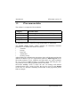
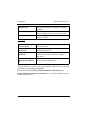
SYncomm modules
The software is composed of four modules:
Category
Associate with
Activities
Tasks management, maintenance and FPU procedures
Comm. Setup
Terminals and protocols parameters
Edit program
Programming terminals
Set-up
Default definitions
Three modules are used for SYncomm setup programming purposes while
the Activities module is where the programmed tasks are performed.
The Comm. Setup module enables defining all elementary hardware
parameters. It is divides into folders as follows:
•
Terminal
•
Groups
•
Protocols
•
Automation
•
Security Group
After defining all communication parameters, these will be integrated into the
different terminals as per user requirements under the Edit Program screen.
SYncomm manages access validation and data tables for Synel terminals:
SY-7xx, SY-4xx, COMM I/II, PRO, TA models, Tango and Time plus. SY7xx terminals can be fully programmed from SYncomm.
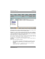
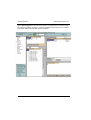
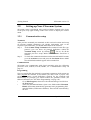
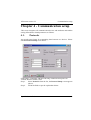
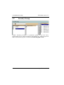
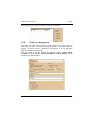
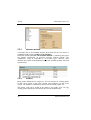
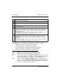
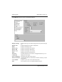
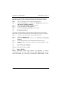
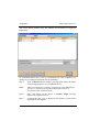
SYNcomm Activity screen is where the user can manage and monitor
communication using various log files that can be viewed in the Results
screen area. It is the most commonly used module. In the page below please
find an example:
2
Synel Industries Ltd.
SYncomm version 5.5
Introduction
SYncomm supports various communication protocols such as: RS-232, RS485, Ethernet via TCP/IP Protocol and a dialling modem.
SYncomm uses other Synel communication applications such as Phantom,
SYNDLL or SYServer to obtain maximal efficiency and speed in managing a
variety of terminals and a wide variety of incoming data from various sources
(from authorized lists, to fingerprint templates etc.).
SYncomm can perform a wide range of auto-task communication activities. It
also provides communication failure notification via e-mail, FTP file
transportation, activity logging, fingerprint management, etc.
In addition, it is possible to present automation results in grid format or
graphically.
SYncomm can be operated as follows:
•
User Operation - Via simple command buttons an operation can be
performed on all defined tasks, or on single terminals or groups of
terminals.
•
Automatic Operation - Programmed activities can be performed
automatically as per a predefined schedule.
Synel Industries Ltd.
3
Introduction
1.2
•
•
•
•
•
•
•
4
SYncomm version 5.5
System Requirements
Intel Pentium processor or higher
RAM 64 Mbyte
100 MB of available hard-disk space
256 color (8 bit) display adapter
800x600 – full color monitor resolution recommended
CD-ROM drive
Microsoft Windows 95, Windows 98, Windows Millennium Edition,
Windows NT 4.0, Windows 2000, Windows XP or Windows 2003.
Synel Industries Ltd.
SYncomm version 5.5
Install software
Chapter 2 -Installation
Insert the CD into the drive, run the setup.exe. Then, follow the listed
guidelines to perform software installation:
2.1.
1.
2.
3.
2.1.
Install software
Insert SYncomm CD into the computer CD drive and follow the step
by step installation procedure, fill-in your name and company name.
The setup program will complete the installation, a message indicates
that installation was successful.
Setup places a SYncomm file on the operating system program list or
creates shortcut icon on your desktop.
Multi-user installation
Install as follows:
Step 1.
Install SYncomm into each PC in the System.
Note:
Step 2.
Step 3.
Step 4.
Follow these guidelines strictly:
1. Open Control Panel| BDE Administrator and in
Configuration| System| Init set Local Share as True.
2. Open Control Panel| BDE Administrator and in
Databases|SYncomm set PATH to the shared database.
All clients must use the EXACT same path to the
SYncomm\DBF alias (same drive or UNC name and same case
for all clients).
3. SYncomm.exe should be run from a local drive, each client
running his/her own copy. Drive mapping is not recommended
(can be accidently deleted)! Use a UNC name (Universal
Naming Connection): \\serverNAME\shareNAME\DBF.
Copy this database into the server (each under a designated
directory).
Each PC must now create a path to these files in the server.
All SYncomm stations must share (full permission sharing) a
server under an identical name.
Synel Industries Ltd.
5
Multi-user installation
Step 5.
Step 6.
Note:
SYncomm version 5.5
Choose the appropriate directory, click OK, confirm the new path.
The program will then Restart.
Repeat steps 1–5 to perform setup for each PC in the system.
You can not run SYncomm twice on the same PC.
SYncomm definitions:
Under Set-up| Multi-user define the following parameters:
1.
Net directory - A shared path (it is recommended to fill-in :
\\PC name\..... i.e: \\synw\sys\SYncomm.dbf).
2.
Drive alias of terminal programming file- Under
Replace: fill-in your PC drive mapping to the programming folder.
With: fill-in the net drive mapping to the programming folder.
3.
For the Edit Program screen:
Temporary directory for multi-user programming-Project
programming data can be stored locally
Net directory- Project programming data can be stored in the network.
6
Synel Industries Ltd.
SYncomm version 5.5
Getting Started
Chapter 3 - Getting Started
3.1.
Screen Layout
All SYncomm module screens share the top menu row. The row below the
top row consists of its 4 modules.
Screen layouts differs between the Activities & Set-up module screens and
the Comm. Setup and Edit Program module screens. The functionality of
each module dictates its unique outline and design.
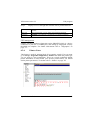
Comm. Setup and Edit Program are divided into three primary parts:
1.
Left side - Logically outlined definition parameter topics. By pointing
with the mouse at either topic, its body screen will appear.
2.
Right side - The body screen of each definition parameter. In this
screen you can fill-in or choose the relevant data.
3.
Bottom - specific screen buttons that enable editing the information
on the body screen or perform a relevant activity. Such as locating net
terminals in the Terminals screen see page below:
The Comm. Setup contains definition folders for communication
parameters.
1
2
3
Synel Industries Ltd.
7
Getting Started
SYncomm version 5.5
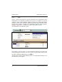
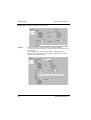
In the Edit Program screen the user chooses a terminal from a terminal type
list, and can generate a project. A project includes all relevant access control/
jobs/T&A definitions for that specific terminal.
8
Synel Industries Ltd.
SYncomm version 5.5
Getting Started
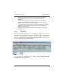
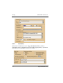
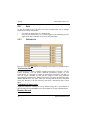
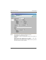
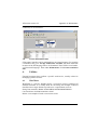
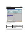
Activities and Set-up module screens are unique:
From the Activities module you can perform and follow-up effectively, on
numerous communication activities.
A
C
B
D
Navigating the Activity screen
The Activity screen is divided into four sections:
Section A The command buttons section which enables communicating
with the terminals. The Automatic activities are activated
when pressing the Start button.
Section B Presents a terminals groups expendable list. This list was predefined in Comm. Setup. Selecting one or more groups from
the list, and than pressing one of the activity command
buttons in section A, will make this command to be
implemented on the selected terminals.
Section C A display screen for each of the required files in section D
pertaining mainly to activity processes analysis.
Section D Enables access to the communication data and logs, present
various file types.
Synel Industries Ltd.
9
Getting Started
SYncomm version 5.5
SYncomm activities
SYncomm commands are organized in a tool bar, applying a command
provides for terminals communication and tasking.
Collect
Collect Data
Re-collect Data
Collect and clear
Collection of transactions from active terminals, since
previous collection.
Collection of transactions including those already transmitted.
Collection of transactions from active terminals, since
previous collection. After collecting the transactions are
cleared from terminal.
Clear data
Clear Data
Clear Data By Date
Clear transactions from terminal buffer.
Clear transactions from terminal according to registered
transaction date.
Maintenance
Get Status
Set Time/Date
Set FPU parameter
Confirm communication connection.
Set terminal’s time and date.
FPU global threshold, such as: very high-low or slave/master.
Download
Programming
Send an application to active terminals.
For SY terminals only:
Update Group 1
Updating terminal’s group 1 by sending specific tables.
Update Group 2
Updating terminal’s group 2 by sending specific tables.
For COM I/II/II Pro, TA78, Tango, TimePLUS only:
Table download
Updating terminal by sending ascii files to terminal.
Send configuration Send terminal configurations.
FPU management
Request template
Send template
Delete template
10
A storage designated for end-unit template on the host
computer. Transmits a request from the host computer to
transfer a template from the end-unit.
A specific template file path on the host computer for transfer.
The unrequired template is deleted from the end-unit.
Synel Industries Ltd.
SYncomm version 5.5
Getting Started
The Set-up screen should be handled by a programmer only, as it requires a
profound understanding of programming implementation. For further
information refer to “Set-up” on page -31.
Synel Industries Ltd.
11
Getting Started
3.2.
SYncomm version 5.5
Setting-up Your SYncomm System
SYncomm setup is performed using task bar buttons located at the lower
screen part or by right clicking on the active screen to display the context
menu.
3.2.1
Communication setup
Terminals
After you have mounted your terminals at their various locations and set-up
all relevant terminal parameters (for further information refer to the
respective Synel manuals), you should define them in the software:
Step 1.
Under Comm. Setup| Terminals define terminal Comm. ID, type,
protocol (you can insert all protocol definitions within the
Terminal Setup screen by clicking
). Do so, for all the
terminals you have set-up. Make sure the Active check box is
marked.
Step 2.
To check the communication between the terminal and SYncomm,
go to the Activities screen and press the Get Status button. Make
sure all defined terminals appear in the terminal list.
Communication
SYncomm can communicate with Synel terminals using the following
protocols: local, modem, TCP/IP, RS485, see “Communication setup” on
page -11.
Programming
Now we must define the terminal’s operational parameters which means we
must program the terminal. In SYncomm you must create a project. The
project incorporates overall definitions required for the terminals full
functionality. In principle you should Follow the guidelines below (for
further information see “SY-780/A Programming” on page -50):
•
Go to Edit Program, choose the relevant terminal type and click on
the New button.
•
Then click the Save As button. Open a new folder under SYncomm|
PROG. SYncomm automatically generates basic programming files
and a dbf folder (SYNcomm’s database). These will be customized by
the user.
12
Synel Industries Ltd.
SYncomm version 5.5
•
•
•
•
3.2.2
Getting Started
On the left hand side of the screen review all the programming
screens: Messages, Input, Valid etc. and fill-in the relevant
information.
You must define your project considering the specific terminal
hardware specifications. According to these you will define what
information the terminal can decode (Input).
To enable employee reporting you must define function keys (under
Transaction+ General) and you must import / insert manually an
authorized employee list.
Define how the terminal will validate each employee’s input data
under Test.
Activities
SYncomm common operations are accomplished via the Activity screen.
Practically launching, all of the activities undertaken between SYncomm and
terminals. The pre-defined parameters within the three Programming
Modules: Comm. Setup, Programming, Program Setup are directed to the
activity module operation and performance.
It is possible to change Activity buttons under: Set-up| Program
Configuration| Activity Screen.
Synel Industries Ltd.
13
Getting Started
SYncomm version 5.5
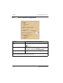
Right-Clicking the Command Panel
Command Panel 1/2
SYNcomm enables creating 2 command buttons. Only
one can be visible.
Communication Program Communication can be disabled or enabled.
Enabled
Use Phantom/SYNDLL/ You can choose which communication program will be
SYServer
used. For further definition see “Communication
Program” on page -39.
Results window section
Right clicking on the results screen or selecting a button from the vertical tool
bar, enables various display options:
Clear
Save as
Phantom File
Show
Clears text in display screen.
Saves the display contents to a file.
Define Phantom as the communication program.
Select a display option, expand Show a submenu lists display
options; Progress, Log Activity, Status, Group collection
statistics, Terminal Error Statistics.
The vertical tool bar option, as follows:
Clear result
Log file
Tables.dat
Phantom.dat
Phantom Result
Load file
Clears information presented on the result screen.
Display log file content on the result screen
Display terminals programming tables path and content on the
result screen
Display phantom programming definitions, on the result
screen.
Display communication messages
Browse to edit an external file.
Show Results (right click)
Progress
Activity default display screen, summaries activities and communication
data.
14
Synel Industries Ltd.
SYncomm version 5.5
Getting Started
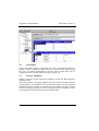
Log Activity
Present a grid option listing all the accumulated activities. Log can be filtered
according to active terminals or present only errors.
Status
A grid format listing the current terminals status, this grid include active
terminals.
The following lists terminal’s performance details:
Full buffer
Error buffer
Send buffer
Empty buffer
File size
Number of full buffers, data transactions up to 128bytes.
Completed or uncompleted transactions are considered.
Number of faulty buffers, include faulty transaction deposited.
Number of full buffers sent and not cleared, all records transmitted
to the host will be considered.
Number of empty buffers, excluding the above calculated buffer
size.
Memory used for tables
Group statistics collection
Displays Activities performed by Groups of terminals. You can choose to
view Group Statistics in graph view or in tabular form.
Terminal Error Statistics
A comparison graph, present each terminal as a bar.
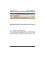
Terminals section
The terminals displayed in the terminal list were predefined under Comm.
Setup module under Terminals. To view a terminal within a group, double
click on the group folder and expand the list. Clicking on one of the terminals
from the list marks it, the check mark indicates that the terminal is active.
Multiple selection is performed by using the buttons on the right of the
Terminal list:
After you locate your terminals (according to number, name or TCP/IP
terminals) by clicking the Detecting TCP/IP Term. button In this section
you can choose on which terminal/s you can perform an activity. The
terminals are displayed per groups. The Terminal Setup screen is available
when marking the terminal and right clicking.
Synel Industries Ltd.
15
Getting Started
3.2.3
SYncomm version 5.5
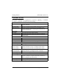
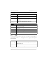
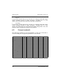
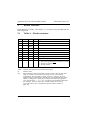
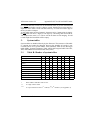
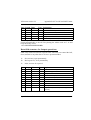
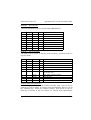
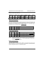
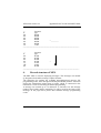
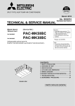
Terminal type activity chart
The various terminal types managed via SYncomm use different activity
commands settings. SYncomm provides an array of commands, few are
compatible with all terminals and others are designated for a specific
terminal. The following table list command usage according to terminal type:
Command
Collect Data
Re-collect Data
Collect and clear
Clear Data
Clear Data By Date
Get Status
Set Time/Date
Set FPU parameter
Programming
Update Group 1
Update Group 2
Table download
Send configuration
Request template
Send template
Delete template
16
SY/
100
400
711/755
715/755
777
780
X
X
X
X
X
X
X
X
X
X
X
X
X
X
X
X
X
X
X
X
X
X
X
X
X
X
X
X
X
X
X
X
X
X
X
X
X
X
X
X
X
X
X
X
X
X
X
X
X
X
X
X
X
X
X
X
X
X
X
X
X
X
X
X
Synel Industries Ltd.
SYncomm version 5.5
Getting Started
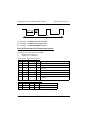
Command
COM
TA
I II pro Ten 71 78
Master Tango Time Plus
Collect Data
Re-collect Data
Collect and clear
Clear Data
Clear Data By Date
Get Status
Set Time/Date
Set FPU parameter
Programming
Table download
Send configuration
Request template
Send template
Delete template
X
X
X
X
X
X
X
X
X
X
X
X
X
X
X
X
X
X
X
X
X
X
X
X
X
X
X
X
X
X
X
X
X
X
X
X
X
X
X
X
X
X
X
X
X
X
X
X
X
X
X
X
X
X
Synel Industries Ltd.
17
Getting Started
SYncomm version 5.5
This page has been intentionally left blank.
18
Synel Industries Ltd.
SYncomm version 5.5
Communication setup
Chapter 4 - Communication setup
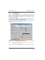
This screen integrates all communication devices and mediums and enables
setting all hardware related parameters as follows:
4.1.
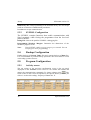
Protocols
An agreed-upon format for transmitting data between two devices. Please
find the Protocol Setup screen below:
SYncomm is compatible with the following communication protocols:
TCP/IP, RS-485, modem, UDP.
Step 1.
Select Protocols from the list, the Protocol Setup screen appears
(above).
Step 2.
Fill-in the fields as per the explanation below:
Synel Industries Ltd.
19
Communication setup
SYncomm version 5.5
The screen is divided in to 2 sections as follows:
Protocol - protocol specifications
Number
When clicking New the system automatically registers a consecutive
number to the last protocol entered. Still the user can manually
change this number.
Description
A designated name to distinguish a specific protocol from other
protocols.
Type
Protocol types available: TCP/IP, modem, local, RS-485.
IP address
the designated IP address or a telephone number (when using a
modem).
Port
Host number when using the TCP/IP protocol (generally is set to
3734).
Properties
Comm port
Com 1, 2 upto 8 (irrelevant for TCP/IP)
Parity
Parity checking refers to the use of parity bits to check that data
has been transmitted accurately. The sending and receiving
devices must use the same parity.
Data bits
No. of bits in a data block (7,8).
Stop bits
No. of bits for signalling the end of data block (1,1.5,2).
Baud rate
Communication speed (1200, 19200).
Retries
No. of attempts to resume communication
Time-out
Time interval until receiving the first character.
Comment - An optional field for the user’s convenience.
To modify existing protocols, double click on the particular protocol; the
Protocol Setup screen appears. Fill-in the new information and then click
OK.ncomm 3 User Manual Setup Y
Customize- You can drag and drop columns from the body screen’s grid and
they will be stored there.
20
Synel Industries Ltd.
SYncomm version 5.5
4.2.
Communication setup
Terminals
Unlike Groups, the Terminals folder enables handling terminal
configuration/programming individually.
To define a new terminal or modify existing terminal definition click the
Terminal folder then click either New or Modify/ double click relevant line.
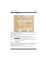
The Terminal Setup screen is divided into three sections:
Terminal
Number
A unique number associates the device’s actual location with the
programmed settings, it is used in the header as a reference.
Type
Select the required terminal from the list.
Location
Terminal actual positioning in the facility.
Synel Industries Ltd.
21
Communication setup
SYncomm version 5.5
Active
When a terminal in not active it serves to enable performing
maintenance activities and system re-organization tasks.
Fingerprint
For SY780A terminals only! Fingerprints can be sampled to be
used either for identification or verification:
Complimentarily, you must go to Set-up | Global | Fingerprint
and define other FP related parameters.
Properties
Protocol name
Give the protocol a name.
Comm. ID
COM port ID number used as an interconnection with a particular
terminal - Synel: 0 - 31, Linear: 0 - 255.
Group
Assigning a predefined programming group
(project+configuration set).
Configuration
set
Enables assigning a different configuration set than the one
chosen under Groups for this group. See “Groups” on page -25.
E-mail address
Fill-in an e-mail address, for notification when an error occurs
(using this module requires pre-definition). The default e-mail
address is defined under Set-up | Global | E-mail Configuration.
Project
For programming you can either choose a project path as follows:
SYncomm Project
Refers to the programming project which you defined under
Edit Program (a *.wsp file).
Or use special parameters as follows:
Special Parameter
check box
For SY terminals only. You can assign upto three programming
files per terminal. when checked provides an interface to an
external programming file.
For SY Family
Dir 1, Dir 2, Dir 3- three external programming files, these
options enables performing independent programming.
Directory for Dir. 4 Terminal-employee specific assignment definitions will be
saved under this directory.
4.2.1
Navigating the terminal module
To select terminals list display options, terminal status or statistics right click
22
Synel Industries Ltd.
SYncomm version 5.5
Communication setup
on the terminal definitions screen to present the context menu.
Modifying terminals
definitions
Editing definitions
Display
Badges/Templates
assigned to terminal/s
Active/Not active
ON/OFF option activates or deactivates terminal
Insert/Modify
Invokes terminal setup menu
enables to insert a new terminal or
modify an existing terminal
Delete
Delete a registered terminal
Print
Use the default printer to print out
the current screen
Copy/Paste
Applying an existing setup to a
new terminal
Grid format
Terminal list is arranged in a
table format, each row contains
a terminal.
Logical tree view
Terminals are organized in an
expendable list. Clicking on the
plus sign reveals terminals
related to a specific group.
Physical tree view
Terminals are organized
according to communication
types; Com, TCP/IP or modem.
Enables displaying a list of the fingerprint templates
stored in the terminal’s memory (verification??).
Customizing column
-
Adding/removing columns from terminals grid format. Press Customize
Fields on the lower tool bar. A submenu presents drag title and place it on
grid header (two arrows marks position). Revers procedure to remove a title
-
Categorize terminals grid according to a pre-defined column header. Press on
Customize Groups, a submenu is displayed. Check the requested category
and press Apply.
Synel Industries Ltd.
23
Communication setup
4.2.2
SYncomm version 5.5
Locating Net Terminals
The Find Terminals screen enables:
1.
Locating live terminals to be defined in the software using the Search
button, than you can Update SYncomm DB.
2.
Class IP Address Search (determines how many works tat ions can
exist on a network) Address Search (range of search): the default
address value assigned is class A. You can fill-in a class type only for
classes B or C.
Type A net card (10Base):
Only the location name can be changed.
Type B net card (New) (10/100Base):
In addition to the location, the following parameters can be changes within
SYncomm:
Server settings- Subnet, Gateway, Local port
Client settings- Server IP, Port
24
Synel Industries Ltd.
SYncomm version 5.5
4.3.
Communication setup
Groups
For the purposes of easy access, time saving and overall maximum efficiency
in programming and retrieving information, you can group terminals as per a
terminal configuration set (see “Sets” on page -38). Under “SY-780/A
Programming” on page -50 you can learn how to create a project for SY-780/
A or any other terminal type. This allows you to deal with multiple units
rather than dealing with each terminal separately. For example, if you have
terminals located in different cities, you can create a different group for each
city. Other scenarios could be grouped according to shifts, or tasks, etc.
Alternately, you can also define different project for the same terminal type.
To create a group you must name it and give a reference number. To enter a
second name and number, click once on the down arrow on your keyboard or
click New; a new line will be created with the corresponding fields for entry.
Terminal programming can be performed using a SYncomm project, or by
interfacing external programming files. Select programming files using the
browse icon as follows:
.
Project
The SYncomm project file path (a *.wsp file).
Setup File
Provides an option to associate a configuration set to a
particular group of terminals.
Synel Industries Ltd.
25
Communication setup
SYncomm version 5.5
Special Parameters
Check box ON/OFF option, when checked provides an
interface to an external programming file.
For SY Family
Dir 1, Dir 2, Dir 3 three external programming files,
these options enable independent programming. For
example: Dir 1 - Main programming table, Dir 2 - Project
programming table, Dir 3 - Authorized personnel table.
After you have finished defining all parameters click the Copy to Terminals
in order to send the updated configuration to all terminals belonging to the
same group.
4.4.
Modems
This module contains all of the parameters required to configure an internal
modem. Upon completion remember to press Save to except the definitions.
Select a Modem, the Modem Definitions list screen is displayed, it is
composed of four folders, as listed:
Init.
The Init. (Initialization) folder contains modem init string. This folder is set
as the default folder. Modem initiation sequence is required for:
•
Disabling error correction
•
Disabling auto baud rate
•
Disabling data compilation
•
Defining a fixed baud rate (2200, 2400, depending on the terminal)
There are five initiation sequence options, If the default init. String is not
applicable to your system the string can be modified.
Press on Choose modem, a submenu containing modems list enables to
select the required modem and baud rate.
Dial
Dial prefix
The modem commands that invokes the modem to initiate a dial
on the remote modem. These commands are sent to the modem
before sending the dial address.
Connect String
This result code indicates that a connection was established.
Dial suffix
The modem dialling commands that are sent to the modem
following the dial address.
26
Synel Industries Ltd.
SYncomm version 5.5
Communication setup
Disconnect
Disconnect
command
A defined disconnect command.
Disconnect String
This result code that indicates that the modem has been
disconnected.
Escape guard time
Sets a period of inactivity to precede and follow the escape
sequence that was configured using the set escape-sequence
command.
Escape character
Promotes the modem command mode after a present online
mode, that is without closing the connection.
Global
Retries
Number of modem riddles after failure to communicate.
OK response
When the modem has successfully executed a command defines
the confirmation string.
Prefix string
An identification string which will precede every string sent from
the modem.
Time-out dial
Waiting time before dialing in milliseconds.
Time-out wait
Waiting time for a reply in milliseconds.
Reset character
A character that will refresh the modem.
Carriage return
Terminates command lines and result codes.
4.5.
USB
A standard that supports data transfer rates of 12 Mbps. A single USB port
can be used to connect up to 127 peripheral devices. Supports also Plug and
Play installation.
Data
Define communication parameters.
Handshaking
When two devices send several messages back and forth in order
to establish an “agreement” on which communication protocol
will be used by each.
Special Chars
Which special characters will be allowed.
Time-out
Waiting time for USB reply.
Synel Industries Ltd.
27
Communication setup
4.6.
SYncomm version 5.5
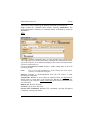
Automation
The purpose of the Automation screen is to enable automatic performance of
the various defined Activities as per a defined schedule. This is an advantage
and is most useful when used during after work time, when the system’s
resources are more available.
The Automation Settings screen enables editing the parameters of a
particular activity within the framework of a specific group, overriding the
settings laid out in Terminals under Comm. Setup.
Click New to add a new activity or Modify to update an existing activity; the
Automation Setup screen is displayed:
If you need to execute a program you must fill-in or choose the relevant
program path in the Additional parameter file field.
Note:
If you set the same priority for two different activities SYncomm
will activate them randomly.
The Activity list contains communication and automatic commands which
28
Synel Industries Ltd.
SYncomm version 5.5
Communication setup
are defined under “Activity screen” on page -40.
In the Priority field choose a number to determine the priority level of the
Activity - “0” equals the highest priority. This field is used when activities
are initiated simultaneously.
In the Length of interval in minutes field, enter the amount of time that
should pass between activities.
In Date range, Hour range and Select day, you can define the time range in
which this activity is operated. Assigning an activity to a group is defined by
selecting In Group default for all the listed groups or specifying a group by
checking one group from the list. Press OK to accept the automated activity,
the Automatic setup screen lists all activities in a grid format.
Groups- the user can assign a terminal configuration group to an activity.
This way, the activity will be performed on all terminals pertaining to that
group as per the defined schedule.
Customizing the automation screen
Click on the Customize button at the lower part of the screen; the Customize
window is displayed. Customizing is performed simply by dragging the
bands from the Automation Settings screen into the Customize window
under the Bands tab and the headers into the Headers tab. These fields will
be removed from the Automation Settings screen to the Customize screen.
In order to replace the bands and headers drag them back.
SYNcomm can be run in automation mode under Run or by: right clicking
the shortcut icon | Properties and adding under the software path under the
Target field: “/a”.
Synel Industries Ltd.
29
Communication setup
4.7.
SYncomm version 5.5
Security Group
Enables allocating terminals to permission groups as per the user’s
requirements (access control, location in your facility etc.). These groups will
later be used when a project is created in the Edit Program module.
30
Synel Industries Ltd.
SYncomm version 5.5
Set-up
Chapter 5 - Set-up
All of the information used and gathered via SYncomm is stored in various
files. When SYncomm works, it is constantly accessing, retrieving and
updating these files. Under Set-up you can define how, where and when this
information will be stored. Also, here you can determine all system default
definitions.
Below please find outlined mandatory elements:
•
Various communication programs configurations
•
Language translation options
•
Terminals and modems
•
Firmware upgrades
•
Fingerprint verification
•
FP Verification/Identification
•
User access permissions
•
E-mail
•
Activities
•
Additional automation parameters
5.1.
Global
Used for various configuration purposes:
5.1.1
Default definitions
These default definitions typify all active terminals and transaction basic
configurations.
All hardware default definitions can be configured here. Terminal specific
definition overlapping default definitions will override them. For further
information please refer to “Terminals” on page -21.
Synel Industries Ltd.
31
Set-up
5.1.2
SYncomm version 5.5
Activities
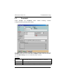
This folder is divided into 3 tabs: Logs, Automation, Files as follows:
The Logs screen is a default layout and routine logging/back-up operations
performed on the Activities screen are set-up here.
32
Synel Industries Ltd.
SYncomm version 5.5
Set-up
The Automation screen is managing automation related extra activities. For
basic automation definitions refer to “Automation” on page -28.
Here you can define command related printing activities and other
automation parameters.
The Files screen consists if the following:
Create DT file set - After data collection SYncomm creates an ASCII file
indicating date and time of procedure - optional.
Status File- Refers to all terminals currently active:
a. For users using the XP operation systems only!
b. If you mark the Error indication check box, an error message will
be displayed whenever there is incompatibility between PC and terminal
date&time.
Synel Industries Ltd.
33
Set-up
5.1.3
SYncomm version 5.5
Edit Program Configuration
Messages
Programming Assistant
screen
Determine messages interface language.
This screen outlines the guidelines for the
programming of SY711/751 terminals. Click the
button.
Day Light Saving Time
Enables maximizing the usage of daylight. Time
adjustments can be made By date or according to
international standards- Fixed algorithm.
Maximum records per table For SY711 terminals, 999 records per table is the
(SY711)
default.
Filter view of edit program: The Valid table includes less data (only card
numbers), therefore more employees can be sent.
34
Synel Industries Ltd.
SYncomm version 5.5
5.1.4
Set-up
Fingerprint
For elaborate description and usage instructions of the fingerprint feature
refer to “Fingerprint” on page -73.
When sending and requesting templates it is possible to filter from which
terminals and the card size.
This feature is currently implemented in the SY-780 terminal only!
Note:
No. of templates can be two only for verification FPU. All other
FPU can enrol+verify only one template!
Note:
Card number can be either 8 (old terminal verification only) or 10
characters (for all other types).
5.1.5
Multi-users
This feature enables performing programming for more than one PC
simultaneously. For further information on multi-user installation refer to
“Multi-user installation” on page -5.
Net directory- SYncomm’s multi-user installation location (server).
Synel Industries Ltd.
35
Set-up
SYncomm version 5.5
Drive alias of programming terminal file section- Enables adjusting drive
mapping per PC to the actual project alias.
For the Edit Program screen section- Enables creating a temporary
database, to allow more than one user to work on the same project.
Note:
5.1.6
Use the Net directory field to fill-in the same alias for all
participating PCs (for either system files or programming files).
Default Locations
Determine here where WinJtrans/MPL builder/Translated files will be stored
5.1.7
Permissions
Enables assigning a password to each employee per employee name. Access
36
Synel Industries Ltd.
SYncomm version 5.5
Set-up
levels are given per software modules (focus on Activities).
5.1.8
E-mail Configuration
SYncomm can send e-mail messages to the operator at various stages of
SYncomm operation. You must fill-in the IP address of your SMTP internet
supplier - it will be used as a default for all terminals. You can determine
when to send the e-mail message.
You can assign a specific address per terminal under: Comm. Setup|
Terminals or under Set-up | Default definitions | E-mail Address for all
terminals as a default address.
Synel Industries Ltd.
37
Set-up
5.2.
SYncomm version 5.5
Sets
As per the terminal type, the user can create configuration sets to manage
transactions storage and format:
•
For Synel terminals there is a fixed format.
•
For Linear terminals there are 10 format types as per terminal type and
application and commands (for Linear terminals only).
5.2.1
Default Set
Here you can create one default set to manage your hardware communication.
Transaction files
A transaction file folder contains standard transaction activities. For the
Linear terminals you can define different parameters unique to your
requirements. It is possible to collect all transaction activities to one file, or,
you can create a number of files for this purpose while using different
(customized) parameters for different activities. For Synel terminals use only
Trans. File 0 field. You must fill-in an existing format from the Phantom
script file. Browse to the file directory and select a transaction file/s. Click
Save.
Command (Linear only)
Additional Phantom commands can be defined using this screen further to
those detailed in the Activities screen. Press Save to accept communication.
Headers Record
38
Synel Industries Ltd.
SYncomm version 5.5
Set-up
Headers are characters which define terminal and transaction identification
and are presented at the beginning of the block. The various header characters
can be included/excluded.
Date/Time
TCP IP
System string
Terminal no.
5.2.2
On/Off check box to include/exclude date/time on the header.
On/Off check box to include/exclude IP address on the header.
On/Off check box to include/exclude message (when this
option is pre-defined). The field right to the check box contains
the string.
Check off this box if you wish the terminal number to appear in
the header. In the field to the right you can enter the number of
positions to be used by the terminal no. (Between 1-3).
Configuration Sets
Here you can create various configuration sets to manage your hardware
communication as per terminal type, see “Default Set” on page -38.
5.3.
Communication Program
SYncomm communicates with terminals using special, communication
programs as follows: Phantom, SYnman and SYNDLL.
Note:
5.3.1
Only Phantom is compatible with all terminal types.
Phantom Configuration
A 32 bit multi-functional communication program that operates with most
data collection terminals manufactured by Synel. It contains fixed scripts and
commands for transmitting programming to the terminal.
Choose the relevant directories for installation and storage of Phantom’s
programming/log files.
Storage of the various communication files is defined here: log, message,
programming, back-up files etc.
Continue in case of an error- Yes/No selection, the system continues
working even though communication with the terminal is disconnected.
Y= Phantom continues running and an error message is not displayed,
N= Phantom stops running and displays an error message regarding a
communication failure.
Show Phantom status window- this will enable viewing communication
processes online.
Synel Industries Ltd.
39
Set-up
SYncomm version 5.5
Send one by one- send programming to the terminals one by one. This helps
avoid an overload on communication procedures.
Press Save to accept communication.
5.3.2
SYNDLL Configuration
The SYNDLL contains functions that enable communication with
Synel terminals, while freeing the programmer from the low-level
protocol details.
Debug File- Choose the path for SYNDLL’s debugging file.
Programming Windows Margins- Determine the dimensions of the
SYNDLL progress screen.
Note:
5.4.
Using SYNDLL enables viewing progress per terminal. You can
view progress when programming!
Backup Configuration
Enables back-up of System, Utility files and a routine back-up of Data files.
It is recommended to perform backup operations after work hours to avoid
overloading system resources.
5.5.
Program Configuration
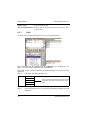
5.5.1
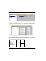
Activity screen
The top section of the Activities configuration screen is the top panel
displayed on the Activities screen. Here we can rename the buttons and
change the communication commands. To change a button click
. The
lower section of the screen corresponds to the specific button you have just
clicked - see the title reading: “Property of Button No. X.
40
Synel Industries Ltd.
SYncomm version 5.5
Set-up
The panel is used for applying the defined commands on all terminals.
Right clicking the command panel enables choosing Automation. The
Automation panel is limited to 5 commands which are defined by default as
Not Active.
FTP
This folder enables exchanging files over the Internet using FTP protocol.
This required in cases such as: After data collection, the collect.dat file can be
sent to the FTP site, or an authorized employee file can be retrieved from the
FTP to be used locally etc.
Fill-in the Password and Name fields to enable editing data in the FTP
(writing/copying).
Note:
Port-21 is an FTP standard port - do not change this value, unless
you have an additional FTP port!
Operate- Whether to download/upload from the FTP before or after
executing the command.
Transfer file- Whether to move a file to or from the FTP at all. Appending or
Delete refers to, when there is an existing file- Whether to add data to the
existing file or to override it. Delete source file refers to the local file that was
sent to the FTP.
Remote file- the FTP file name.
Local file- the local PC file name.
Execute FTP Command- Running FTP commands- specially designated
commands- consult your dealer!
Synel Industries Ltd.
41
Set-up
SYncomm version 5.5
Display
Fill-in the button title and a confirmation question before carrying out the
activity if such is required. Then, match a sub-screen as per the relevant
parameters to the button’s function. See the screen below:
Run
Enables running a batch file or an application before or after executing the
command.
WinJtrans- Converts file structure, such as Synel transaction file to a different
structure as per user requirements.
42
Synel Industries Ltd.
SYncomm version 5.5
Set-up
Command
Similarly to the Configuration set, as per the terminal type, command
structure is determined here. SYncomm knows the structure for each
terminal. The Help button provides a useful index for command codes.
In Phantom and SYNDLL the command always begins with “100,” followed
by the command text (for further information you can refer to the SYNDLL
manual or Phantom manual).
5.5.2
Terminals
Used for setting-up terminal configurations in terms of operation, form - see
further documentation in SYncomm’s technical manual. Enables removing
any irrelevant terminals which are not in use, to avoid operator mistakes.
Synel Industries Ltd.
43
Set-up
5.5.3
SYncomm version 5.5
Default Modem
A inventory list of all available modems from which the user can choose a
compatible modem in the Comm. Setup| Modems.
In the ISO modem (New SY-780 Terminal Modem...), launching string does
not require cancellation of previous intricate modem options. The
AT&FEOV1 string is compatible to all modem types. Whereas, other
modems may require such adjustments as per the installed modem's technical
specifications.
5.5.4
Printer
Basic printer definitions are setup here. You can activate an existing printer
or add a new printer in the upper section, and configure it in the lower
section. The outlined commands are instilled in SYncomm’s MPL file.
The printer code can be found in the printer’s user guide. You can copy
existing printer definitions and change the relevant data manually.
44
Synel Industries Ltd.
SYncomm version 5.5
Synel Industries Ltd.
Set-up
45
Set-up
46
SYncomm version 5.5
Synel Industries Ltd.
SYncomm version 5.5
Edit program
Chapter 6 - Edit program
The programming module deals with overall terminal definitions. For each
terminal type it is possible to edit a project. A project consists of rdy files (for
a format description refer to the SAL manual), the SAL implements the
instructions it is given by SYncomm’s tables. The project also consists of a
def directory and a *.wsp initializing file.
Programming parameters vary from terminal to terminal, yet the principle
procedure is similar. Programming is compatible with each terminal’s
hardware apparatus and capabilities. Below please find a general outline:
6.1.
Synel terminals
SY100
For this terminal it is possible to define:
ValidNon valid listRangeAnti-Pass-Back-
Authorized employee list
Unauthorized employee list
A number range to be validated (card number, date etc.)
Prevents a card from being swiped twice in the same reader.
Enables anti-pass-back for all readers pertaining to a specific
Master.
For the following terminals it is possible to create a full programming project
and characterize terminal behaviour when communicating with a reader/
sensor. Employee tables can be defined including validation of an authorized
list, a PIN code and TZ (For further information on Time Zone refer to “SY780/A Programming”):
•
SY-400
•
SY-711/751
In addition it is possible to define function key structure (1/16 display) and
under Input- various terminal reactions to input exceptions.
•
SY-715/755
It is possible to define function key structure (1/16 display) and under Inputvarious terminal reactions to input exceptions.
In addition a 2/16 display and a KB Input type.
Synel Industries Ltd.
47
Edit program
SYncomm version 5.5
•
SY-777
It is possible to define function key structure (1/16 display) and under Inputvarious terminal reactions to input exceptions. Available also is a 2/16
display and a KB Input type and multi-step Input management.
•
SY-780/A
It is possible to define function key structure (1/16 display) and under Inputvarious terminal reactions to input exceptions. Available also is a 2/16
display and a KB Input type and multi-step Input management. Also, this
terminal enables fingerprint enrolment and validation.
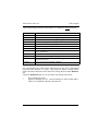
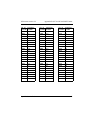
6.2.
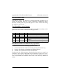
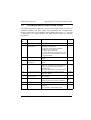
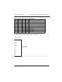
Linear terminals
The following terminals are not programmable. In this case SYNcomm is
used for sending the configuration parameters to the terminal.
Tango TimePLUS TA71
Permitted
Category
Department
Job
Time Zone
Time Zone Groups
Bell
Automation
Messages
Error Messages
Days
Function Keys
Reports
Printers
48
X
X
X
X
X
X
X
X
X
X
X
X
X
X
X
X
X
X
X
X
X
TA78
COM I
X
X
X
X
X
X
X
X
X
X
X
X
X
X
X
Synel Industries Ltd.
SYncomm version 5.5
Edit program
The programming parameters listed below are common to Synel terminals:
Messages
Input field
Valid
Non-Valid
Employee
Time zone
Test
Transaction
General
Weekly
Daylight saving
System
Scheduler
Messages list (system errors, rejected or accepted activities).
Data format definitions and field properties.
Authorized files sorted according to badge format.
Restricted files sorted according to badge format.
Presentable employee names, projects and codes.
Scheduled time interval per group.
Test definitions provided for each terminal function.
Function keys description and transaction ID.
Terminal function keys position, general parameters and FPU
sensor parameters.
Daily terminal functionality.
Enables scheduled daylight saving.
System parameters (Memory, control badge, date formats and
terminal operation).
Function keys/Relay/Modem schedules.
COM II Pro
For programming the COM II Pro SYNcomm uses the TA-75 application
Generator (also referred to as PEP). This generator enables creating ASCII
tables and import them into SYncomm and viewing the data under Database
tab.
Under the Definitions tab you can not make any changes other than:
•
Day Light Saving Time
•
Options | Memory fill in % - must be identical to same in PEP under:
Tables | Event Handle | Memory Full Percent
Synel Industries Ltd.
49
Edit program
6.3
SYncomm version 5.5
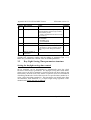
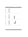
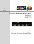
SY-780/A Programming
Programming Flow Chart
System tables
Firmware
SAL Programs
(JPL)
JAL Parameters
(JPR)
Scheduler
(FTS)
System
(SYS)
Program tables
Gen
Gen
Weekly
Message
Gen
Gen
Fun
Gen
Fun
Input
Test
Valid
Emp
Data tables
Non Valid
There is an inter-dependency between the different *.jpr tables built by the
SAL program which are the body of the application.
SYncomm builds the tables as per SAL requirements. On the next page
please find a brief outline of the role of these tables.
The correct and logical order for building a project is to begin from the
bottom of the flow chart as follows:
Mandatory
1.
2.
3.
4.
5.
50
Input
Test
Transaction (Test + Input)
General (Transaction to Function Key)
Weekly (General to day of week)
Synel Industries Ltd.
SYncomm version 5.5
Edit program
Optional
1.
2.
3.
4.
5.
6.
7.
8.
6.3.1
Employee, Valid, Non valid - optional
Messages
Time Zone (to be linked to an employee)
Printer notes (i.e.: for meal labels)
Day Light Saving Time
System
Scheduler- for relay/modem activated function keys
Project info - general information which is not transmitted to the
terminal
Messages
Fixed system messages. These messages can be edited or re-written.
6.3.2
Input
Enables defining upto 4 Input sources that typify a reader/sensor. Input
sources are as follows:
Magnetic track 1 (ANSI) Requires swiping of an employee card
Magnetic track 2 (ANSI) Requires swiping of an employee card
Proximity
Requires placing the card upto a distance of 6-8 cm from
the reader
Touch memory
Bar code 3/9
Bar code 2/5
A laser read identification code.
Bar code 128
Codabar
Keyboard
Using the terminals interface key-in card number.
Sensor 1
A sensor can activate either a buzzer or a LED.
Sensor 2
Date
Validation of date format (input mask)
Time
Validation of hour format (input mask)
Scroll in list
A list to be displayed on the clock prompt from which the
user can choose the relevant data (without card) and
scroll using the arrow key.
Synel Industries Ltd.
51
Edit program
SYncomm version 5.5
Printer ready
Printer signalling input.
FPU Auto-identification Enables defining fingerprint identification only (no card
fixed 10 char.).
6.3.3
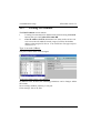
Valid
An list of IDs of authorized cards. See screen in the page below:
Please note that the IDs indicated in the Employee (see “Employees” on
page -53) table and the valid table must be identical!
The Valid screen is used for defining and determining access levels for each
employee:
Step 1.
Fill-in the Valid table header row:
Header
Table name
ID
Record size
Type
Key length
Step 2.
Step 3.
52
These constitute the header (structure) of the
valid table. The data will be filled-in on the
right.
On the right fill-in all authorized employee numbers.
On the bottom the user can allocate permitted terminals to each
employee.
Synel Industries Ltd.
SYncomm version 5.5
Note:
Edit program
The Valid table ID SHOULD NOT be identical to the Employee
table ID.
6.3.4
Not Valid
Parameters identical to those of the valid table but used for denying access to
specified employee cards.
6.3.5
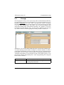
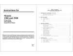
Employees
Here you can assign an employee list/employee to a terminal. More than one
authorized employee table can be imported from an external database
Unlike the “Valid” table, this table includes various employee details as you
can learn from the table below:.
1
3
2
5
Synel Industries Ltd.
4
6
53
Edit program
1
2
3
4
5
SYncomm version 5.5
Employee table header (name). It is possible to import various employee
tables from an external text file.
The updated terminal list into which updated employee files will be sent.
Employee authorized list lay out. Here, employees can also be added
manually!
A list of the terminals to which authorized employees can be assigned and
thus allowed access.
Additional features that can be used or disregarded:
Create message table/Create scheduler table/Create total hours
table- these are employee specific messages to be displayed for the eyes of
that employee only!
Add employee name/Assign Terminals/Security group - these are
6
fields that can be either used or not this screen.
A series of editing buttons and a few functional buttons as follows:
Fingerprint - Enables fingerprint management: enrolling a fingerprint,
determining the threshold etc. For further information refer to “Fingerprint”
on page -73.
Time Zone Groups - Defines a time-frame in which access is permitted.
Time Zones are defined day types for a period of one year.
The Employees screen enables performing the following procedures:
•
Assign an employee to the specified terminals.
•
Sending the requested template to a terminal.
•
Use host computer to perform enrolment per employee.
•
Determine employee’s fingerprint security threshold.
Selecting employee permissions per terminal/group
Step 1.
Step 2.
Step 3.
Step 4.
54
Specify a table name from the Table name field.
Employee records are displayed in a table format.
You can either mark the Assign Terminals check box to assign
employees manually to a terminal/s, or the Security Group check
box to assign employees according to a security group.
If you use the Assign Terminals option, you must now add a
terminal to the Permitted terminals for a specified employee.
Mark one or more terminal/s on the Terminals list and use arrow
to move it to the permitted terminals list.
Synel Industries Ltd.
SYncomm version 5.5
Step 5.
Select All
Clear All
Properties
Edit program
Employee access through that terminal will be permitted/denied.
Select all terminals from list, a check sign marks the selected
terminal.
Clear all terminals, a circle marks the unselected terminal.
ON/OFF option defines communication software properties.
FPU management
Enables enrolling employee fingerprint (using PRintX/H which is a device
connected to your PC’s COMM port) and setting-up fingerprint security
threshold per template. For further information refer to “Fingerprint” on
page -73.
6.3.6
Printer Notes
This feature is used for printing labels (For example.: meals). First you must
go to Set-up | Program Configuration | Printer and define the printer type
you are using in your organization. There are several predefined default
printer definitions. If none match your specific printer brand, you should
define printer parameters. To do that refer to “Printer” on page -44.
Synel Industries Ltd.
55
Edit program
6.3.7
SYncomm version 5.5
Test
This is a mini set-up table for activities and terms to be performed on the
transactions. It is possible to perform one activity or a sequence of several
activities. Some of the relatively simple activities are: saving transactions,
employee access/other validation, displaying specific timed messages. Some
of the more complex activities are: calculation activities (sum, subtract,
multiply, compare etc.), variable to variable, inter-buffer activities.
The Test table is divided into 2 parts:
HEADER
BASE
The header is the test name, it is recommended that the given name will
portray the purpose of the test, see above screen. A new header can be created
by either clicking the New button or the
key.
The base part is where actual definitions are set, when double clicking a row
the following screen appear:
56
Synel Industries Ltd.
SYncomm version 5.5
Step 1.
Step 2.
Edit program
Fill-in a test name and number.
The templates are comprised of different activities:
Most templates are divided into 3 parts:
Operation- A check to be performed, different from template to
template.
OK- Further to the operation how to confirm or what other
activities will follow. Similar for most templates.
Fail- Further to the operation how to indicate that the operation
has failed. Similar for most templates.
Synel Industries Ltd.
57
Edit program
SYncomm version 5.5
The OK/Fail sections screens are displayed below:
Display message
Enables choosing a constant message from the system messages
list.
Display end
Enables displaying variables of input data.
Relay
Enables activating a relay.
Buzzer alert
Enables activating an alert buzzer.
Buzzer OK
Enables activating an OK buzzer.
Buzzer error
Enables activating an error buzzer.
Wait
Waiting time between transactions.
Write last
Transmits data that was stored in a designated directory, to be
transaction
displayed a later stage.
Store transaction Determine what data will be stored.
Write transaction Transmits data that was stored to the terminal’s memory. Cannot
be displayed.
Go to module
Enables a cyclic flow to the same transaction.
End
The terminal reverts to the defined default function.
58
Synel Industries Ltd.
SYncomm version 5.5
Edit program
Buffers: What data will be displayed on the terminal’s prompt:
N - None
I - Input data
L - Input length
P - Input source
F - File buffer
S - File status
R - Transaction
C - Constant
No check will be performed.
The last value that was received by the terminal.
The Number of designated spaces for counting total value
length.
From which source the last input has arrived, upto four spaces:
1st=type, 2nd+3rd=reader number, 4th=status.
The results of a table search (either employee or valid)= the last
record (approx. 30 spaces).
The status after performing the last command.
Before storing the transaction it can be compared.
Free text to be filled in Constant field below.
Below please find an outline of defining Operation for templates:
Length check
Defines the input length limitation (KB, card number, identification
ID etc.) and the offset of that input number.
Synel Industries Ltd.
59
Edit program
SYncomm version 5.5
Check value
Enables comparing field variables.
Operate
Enables performing various calculations between buffers.
i.e.: This feature is useful when printing, for placing variables in the
printer buffer:
AD= summary, SU= subtract, MV= Move, AN=Pairing bytes
logically, OR= alternating 2 bytes logically, XR=Exclusive XOR
operator, NU=numeric check
60
Synel Industries Ltd.
SYncomm version 5.5
Edit program
Source check Enables checking:
Primary source is the input source: what reader is operated.
According to this the software will apply accordingly.
The reader number is a secondary source.
Reader Status code is unique for each output type as follows:
Readers- E= read error, D=data read OK
Keypad- N=numeric or Enter key (If only Enter then IL=0)
Sensors- A= Active, P= Passive Note: IL=0
Printer- A= Active, P= Passive
File check
Enables validating an authorized list with one of the tables on the
Locate section. Under File choose the specific file.
Query
Write last
transaction
Store
transaction
Write
transaction
6.3.8
A query is sent to the software that is performing an online scan using SYServer.
Enables saving the last transaction setup in a temporary file for later
display as t he employee’s last transaction.
Enables adding transaction data to a buffer.
Enables saving all transaction steps (see Transaction folder) in
the terminal’s memory. Later this data can be collected by the host.
Transaction
In this screen the user can define a multi-step transaction, combining Test,
Input and prompt message definitions. The screen shot below demonstrates
the enrolment procedure that requires a supervisor card to be swiped first.
Synel Industries Ltd.
61
Edit program
6.3.9
SYncomm version 5.5
General
Combines the transaction definitions with a function key on the terminal’s
panel.
Define all hardware parameters:
Key function- Determine function allocation to terminal keys.
Display parameters- What error message will be displayed on the prompt.
Also you must choose a date/time format as per the terminal you are using as
follows:
DD/MM
MM/DD
HH:mm
HH:mm a/p
DD/MM HH:mm
MM/DD HH:mm
DD/MM, a/p HH:mm
MM/DD, a/p HH:mm
62
711/715
777/780
Synel Industries Ltd.
SYncomm version 5.5
Edit program
Global parameters- Timing of terminal activities.
Sensor parameters- sensor operational parameter.
Error notification- Setting-up error indicators.
6.3.10
Weekly
Combines General definitions of the terminal function keys with a day of the
week. Thus, the terminal can be used differently for each day.
Synel Industries Ltd.
63
Edit program
64
SYncomm version 5.5
Synel Industries Ltd.
SYncomm version 5.5
Appendix A: Maintenance
Appendix A: Maintenance
This menu which is located on the top of your SYncomm screen, allows you
to easily implement systematic communication reparation procedures such
as:
1.
Back-up
Enables backing-up system and utility files to a predefined location. Data
files can be backed-up on a regular basis as per a predefined recurrence.
2.
Restore
Enables retrieving system/utility and data files from backup. In SYncomm
restoring can be done per terminal and for a specified date range. Also other
activities can be performed on the restored files using SYncomm utilities.
3.
Advanced
3.1
Re-index
Enables rearranging table indexing if previous indexing was distorted.
3.2
Build indexes
Enables refreshing program tables index.
3.3
Return All Program Settings to Default
Enables the user to revert to the initial system Set-up definitions. For further
information see “Set-up” on page -31.
3.4
Upgrading firmware - SY780 terminals
Caution: The new firmware will override the old firmware.
Make sure you collect data from the terminal before upgrading!
Upgrading firmware can be implemented as follows:
•
As of version 6.204 for all the 6.xx series versions.
•
As of version 7.204 for all the 7.xx series versions.
•
As of version 8.0 for all the 8.xx series versions.
Synel Industries Ltd.
65
Appendix A: Maintenance
SYncomm version 5.5
This option is limited only to authorized personnel (usage of a password)!
EPROM upgrades can be sent from SYncomm to the terminal as follows:
Note:
The new firmware will override the old firmware!!
Step 1.
Click the Activities icon. Under the Maintenance menu go to
Advanced| Upgrading firmware.
Choose the relevant upgrading firmware file.
Choose the terminal to be upgraded.
Confirm sending programming to the terminal.
Step 2.
Step 3.
Step 4.
3.5
Formatting memory
This option is limited only to authorized personnel (usage of a password)!
SYncomm can erase all transactions from the terminal’s memory as follows:
Note:
Perform collect data before starting this operation.
Step 1.
Step 2.
Click the Activities icon.
Under the Maintenance menu go to Advanced| Formatting
Memory.
Choose the terminal/s to be formatted (the default is none).
Define whether SYncomm should sent programming to the
terminal.
Step 3.
Step 4.
3.6
View SYncomm database
Enables viewing SYncomm’s database.
3.7
Report Builder
Enables submitting various SQL queries via SYncomm to retrieve
accumulating data. To insert a table click the Add Table button. A subscreen will enable you to browse your data base. Related tables can be
66
Synel Industries Ltd.
SYncomm version 5.5
Appendix A: Maintenance
connected, see screen below:
3.8
Create translation files
SYncomm’s interface can be translated into any target language. For creating
a translation file go to: Set-up| Global| Def. Location you must define the
location of the INI language files to be translated. These will be saved under:
x:\SYncomm\Language. Then under Maintenance click Create translation
files.
4.
Utilities
External programs that perform a specific task/service, usually related to
managing system resources.
4.1
WinJTrans
WinJTrans is a tool for building freely a conversion project comprised of
different formulas. It is usually used for converting for example: collected
data files into a target format as per the user’s requirements, such as:
String from terminal: d0006132260603B2021659000000000000034
Converted into: 00 000034 260603 16590J
Below is an example of such a conversion screen:
Synel Industries Ltd.
67
Appendix A: Maintenance
SYncomm version 5.5
For further information you must refer to our technical support department.
4.2
Check RDY
Checks the format (RDY) of the data files sent to the terminal from the
software. When creating new RDY files you can check their legality using
this tool. For further information on Synel’s RDY format files refer to
“Appendix B: SY7xx/SY4xx-RDY Format” on page -81.
4.3
Convert Templates
Enables converting Synel fingerprint templates format into BII fingerprint
template format.
This utility enables converting templates that were stored in an MV1200 unit
to Synel format; The templates are received directly from your FP unit using
an MV1200 demo software, converted into Synel format and sent to Synel
terminals using Synel software. This a reciprocal process: templates can be
converted also from Synel format into MV1200 format.
68
Synel Industries Ltd.
SYncomm version 5.5
4.4
Appendix A: Maintenance
Update Day Light Saving Time
Enables setting-up daylight saving time usually in correspondence with
seasons (maximizing daytime usage in Winter- shorter daytime and longer
daytime in Summer). With exceptions for specific projects, for further
information “SY-780/A Programming” on page -50 and “Edit Program
Configuration” on page -34.
Synel Industries Ltd.
69
Appendix A: Maintenance
70
SYncomm version 5.5
Synel Industries Ltd.
SYncomm version 5.5
Appendix A: Maintenance
This page has been intentionally left blank.
Synel Industries Ltd.
71
Appendix A: Maintenance
72
SYncomm version 5.5
Synel Industries Ltd.
SYncomm version 5.5
Fingerprint
Chapter 4 - Fingerprint
The fingerprint feature is available from SYncomm 4.4 and later versions,
with SY-780 terminals and PRintX (via PC).
Note:
All firmwares support verification for a 6 digit ID. A 7-8 digit ID is
supported by 5.115, 6.101 and later versions. A 9-10 digit ID and
identification are supported as of firmware version 6.200.
The FPU-S unit is supported as of version 8.003.
Unit Types:
Identification
does not require a card/code. Upto 200 fingerprint templates are stored in the
terminal’s memory. Whenever an employee places his finger on the sensor,
the Fingerprint (FP) unit polls all existing templates until there is a match and
confirms/rejects.
Verification
requires a card/code. The template is stored in reference to a card/code. Upto
4000 (FPU-S= 1000) card/codes and templates are stored. When an employee
swipes his card/keys-in his code, the unit checks if the card/code number
exists, if it does it checks also the template assigned to that number.
The differences between fingerprint identification and verification are:
•
Identification does not require a card/code. Upto 200 fingerprint
templates are stored in the terminal’s memory. Whenever an employee
places his finger on the sensor, the unit polls all existing templates until
there is a match and confirms/rejects.
•
Verification requires a card/code. The template is stored in reference to
a card/code. Upto 4000 card/codes and templates are stored. When an
employee swipes his card/keys-in his code, the unit checks if the ID
number exists, if it does it checks also the template assigned to that
number.
MV1200 Method
FPU-S Method
4000
1000
Verification
200
1000
Identification
Card number can be either 8 (verification only) or 10 characters (verification
Synel Industries Ltd.
73
Fingerprint
SYncomm version 5.5
and identification).
The basic biometric concepts are:
Enrolment
Scanning a fingerprint, determining quality of the scan and storing a good
template as a reference. Enrolment is confirmed and scanning quality data is
outlined. Scanning quality is a by-product of the skin’s condition: dry skin
can contribute to an unreliable image. A normal amount of moisture on the
skin makes the ridges and valleys of the fingerprint stand out to the sensor.
Too little moisture makes the image “noisy” and causes PRintX/H to reject
the image during processing. Lightly moisturizing the finger will enhance the
contrast of the print and provide a more reliable template. An increased
sensitivity of the silicon sensor can dramatically reduce such problems.
Verification
Proofing of the current scanned fingerprint against the stored fingerprint
templates for that user:
Quality
The quality score is based on how well the ridge pattern is defined within the
fingerprint image that was enrolled. Quality measures how clearly the unit
imaged the fingerprint. Poor quality enrolment can result in an elevated rate
of false rejection making it difficult for the user to verify reliably. The score
ranges from 0 to 100. A 100 is the best quality (rarely obtained) and 0 the
worst. Quality scores of 40 and higher perform well with the verification
algorithm that readily compensates for differences in fingerprint.
Content
The Content score is based on the amount of usable information the unit sees
in the fingerprint. Templates that are characterized by low content scores may
result in elevated rates of false acceptance.
The score ranges from 0 to 100. A 100 is the most content and 0 the least.
Content scores of 20 and higher perform well with the PRintX/H. In this
range the algorithm has enough information to distinguish between different
fingerprints with a high level of accuracy. Templates with content scores
above 20 do not vary in terms of the error rates.
74
Synel Industries Ltd.
SYncomm version 5.5
Fingerprint
Hardware
First, the following devices may be connected:
1.
A PRintX/H fingerprint unit must be linked to the PC via the COM
port.
2.
PRintX-I/V (identification or verification or FPU-S) fingerprint unit
linked to the SY-400/A terminal.
3.
SY-780/A has a built-in FP unit.
Caution: Use an external power supply for the PRintX/H fingerprint unit!
Software
After you have connected the PRintX unit to your PC COM port, you must go
to Set-up | Fingerprint and define:
•
A path in which your templates will be stored.
•
The COM port used by the PRintX fingerprint sampling unit.
•
A fixed baud rate: 57600.
•
Do not change the Net ID!
Also, Define a default project under Setup | Default definitions | Default
project.
You can access the Fingerprint Management screen either from:
Activities | Template Mang. or from:
Edit Program (choose SY780) Employees | Fingerprint
Then, you can use PRintX/H for enrolling templates to SYncomm (to the path
that was specified under Set-up).
Synel Industries Ltd.
75
Fingerprint
SYncomm version 5.5
The screen below enables using the PRintX for enrolment of employee
fingerprints.
PC enrolment allows one (or two in verification FPU only) template/s per
employee (according to fingerprint set-up definition).
Step 1.
Press the Enrol button to sample your fingerprint. Place the finger
on the designated place on your PRintX device.
Note:
Make sure that before enrolling you define the same PRintX type
you have in SYncomm (Verification/Identification/FPU-S
Verification/FPU-S Identification).
Step 2.
Place your finger on the device. A Remove finger message
appears and a green led is lit.
A fingerprint scan score is displayed (See quality, content at the
beginning of this chapter).
Step 3.
76
Synel Industries Ltd.
SYncomm version 5.5
Fingerprint
Step 4.
In case the user wants to re-scan he must click No and revert to the
Fingerprint screen.
Step 5.
If the user wants to confirm, he clicks OK. A “Template saved to
disk” message appears.
Step 6.
the writing under the Template? column for that employee will
read Yes.
Step 7.
Repeat steps 1-6 for each template (there could be up to 2
templates per employee).
Step 8.
Click Verify and a “Verified”/“Verification failed” message will
appear.
Step 9.
Under Activities, click Send All Templates, to send the new
templates to the terminal.
Step 10. If sampling becomes problematic, change the Security threshold
score requirements, i.e. from Very high change to Low.
The enrolment procedure can be repeated upto three times. A failure in all
attempts will result in reducing the threshold value for that specific employee.
In a successful sampling a template file will be created. A file is saved under
the host computer default path, its name includes 8 digits as per employee
number and an FG1 suffix.
Setting FPU parameters
Press Set FPU Parameters button from Activities screen on SYncomm main
menu, a submenu appears. Click a radio button Option to select global
threshold settings, listed in ascending mode from the highest security level to
the lowest. The last two radio button sets update initiating mode, master or
slave.
For further information on the FPU
Personal Security threshold (level)
The compatibility level between scanned fingerprint and the reference
template is defined as the threshold. The security level, which is specified per
each employee, is changeable when a low scoring of fingerprint sampling
occurs. During verification procedure, FPU uses the lowest security level
defined in the global threshold against personal threshold stored within the
template. The following procedures enable changing an employee’s personal
threshold.
Synel Industries Ltd.
77
Fingerprint
SYncomm version 5.5
Changing employee threshold
Select an employee from table. Click the Security button on the lower tool
bar. Change employee threshold submenu appears:
•
Current displays employee security level.
•
New enables customizing employee security level.
Acknowledge modification by clicking Change button or disregard it by
clicking Cancel.
78
Synel Industries Ltd.
SYncomm version 5.5
Fingerprint
Requesting/Sending/Delete template/s (buttons)
Choose the relevant terminal, then request/send/delete templates from that
terminal according to the following parameters (note: you can perform this
activity for one employee table at a time):
Select according to:
Use Template Number
Insert a template number manually. This
command ignores employee list and requests a
specific template number.
Use External List
Import an authorized employee ASCII file.
Under Setup | Fingerprint | Request/Send/
Delete Template...
Synel Industries Ltd.
79
Fingerprint
SYncomm version 5.5
Review Terminal
Template List
Before performing the activity review terminal
template list and act according to the defined
condition.
Selected Employees
Send employees that were moved to the
Selected Employees area (see above screen).
All Employees
Send all employees and act according to the
defined condition.
Conditions:
Do not request templates To save time and resources, only new templates
that exist in PC
can be requested.
Refer to terminal
template list
Before performing this command check
terminal template list.
Disregard project
definitions
Perform an activity although it does not
coincide with project definitions (template
allocation).
Start command by
updating PC template
list
Before performing this command synchronize
PC and terminal template lists.
You can define here a path for storing the templates different from the default
path defined under Setup | Fingerprint.
Project- Defined under Setup | Default Definitions | Default Project
Badges/Templates assigned to terminal/s- A view of the templates stored in
the terminal’s memory.
80
Synel Industries Ltd.
SYncomm version 5.5
Appendix B: SY7xx/SY4xx-RDY Format
Appendix B: SY7xx/SY4xx-RDY
Format
1.
General
Synel’s terminal has a special format for internal tables (files). The table
contains a header that determines its general information and structure, and
data records. The table can be divided into two groups: Tables that are
handled directly by the firmware and user defined tables. The first group –
System tables has a pre-defined structure that cannot be changed by the user
or the application. The user uses the SAL application to adjust the tables to
his requirements.
This document will describe the general structure of the tables and the
structure of system tables.
Special characters:
Character
Limitation
> 7F
A character greater than 7F hex can not be sent to the terminal.
EOT
04 hex – End of Transmission
ACK
06 hex - Acknowledge
CR
OD hex will be ignored – not sent to the terminal
LF
OA hex will be ignored – not sent to the terminal
__
5F hex will be ignored – not sent to the terminal
A string beginning with f1 (01 hex) will be considered as a comment and will not be
sent to the terminal.
Synel Industries Ltd.
81
Appendix B: SY7xx/SY4xx-RDY Format
2.
SYncomm version 5.5
Header structure
Each table has a header. The header is a 23 bytes string divided into the
following fields:
2.1
Table A – Header structure
Byte Length Value
Type Explanation
1
2
5
1
3
5
A&N Table type – Used as part of file identification
N
Table ID – for file identification
N
Total table characters
10
11
13
15
18
20
22
1
2
2
3
2
2
2
A&NNSN-
82
A-z
001-999
0002399999
0-z
23
00-99
000-|99
00-99
00
00-03
A&N
N
N
SN
N
N
N
Table version
Header Size
Record size - total number of characters in a record
Number of records in table
Key length
Key offset (a fixed value - not in use).
00 – Not sorted, not packed
01 – Not sorted, packed (Only in numeric records!)
02 – Sorted, not packed
03 – Sorted, packed
Numbers and characters are allowed in this field.
Numeric field
Special Numeric field. This format is used in order to increase the value
range in a numeric field without increasing the size of the field for
compatibility. The algorithm is simple, there is no change in the least
significant bytes of the number, and only the most significant byte of the
number is changed to a character according to the following algorithm:
10 is represented by “:”, 11 “;” etc. according to the standard ASCII table.
For example: If the records total in a table is 2049, then it will be
converted to D49. (See “Algorithm for Synel’s numeric fields” on
page -96).
Synel Industries Ltd.
SYncomm version 5.5
Appendix B: SY7xx/SY4xx-RDY Format
In a sorted table the records are in incremental order as per the defined field
key. The sorted table search is a binary search, therefore there must not be a
duplicate of the same record with the same key. In such cases add a digit to
the key to make it unique.
A pack table must consist of numeric characters only. Compression is simple,
the terminal will store 2 digits in one byte by converting ASCII into BCD.
The compression ratio is 1:2. There will be no data record merging. In odd
record length the last nibble will be empty.
3.
System tables
System tables are handled directly by the firmware. The structure of the table
is constant and cannot be changed, however the number of records is not
constant. There are 5 System tables: Task Scheduler Table (FTS), Messages
table (MPL), System Parameters Table (SYS) and Program tables like JPL,
JPR, TRS/TRP Font translation table files (FNT).
3.1
Table B- Header of system tables
Field
FNT FTS SYS MPL JPL JPR TRS* TRP*
Table type
Table ID
Total number of characters in
table**
Version of table
Header Size
Record size
Number of records in table***
The key length
Key offset ( a fixed value-N.A).
Table attributes:
g
e
p
d
001 001 001 995
----- ----- ----- -----
j
v
m
001 001 001
----- ----- -----
m
001
-----
A
23
16
A
23
23
A
23
A
23
68
01
00
02
04
00
02
00
00
00
04
00
02
A
23
16
--04
00
02
A
23
06
--02
00
02
*
**
***
A
23
----00
00
00
A
23
04
--00
00
02
Either TRS or TRP files will be sent.
A 5 digit numeric field
A 3 special numeric field: 1st =ASCII, 2nd+3rd=numeric (see Appendix A)
Synel Industries Ltd.
83
Appendix B: SY7xx/SY4xx-RDY Format
SYncomm version 5.5
Task Scheduler table
This table is used by the firmware to perform automatic operations per a
specific day and time. There are 3 types of operations: Changing the active
function, activating the relay (for bell purposes or door control) and setting
the modem to auto-answer.
Task Scheduler record format
The record is 23 bytes long. The data field is modified according to the
operation code. See the record format in the page below:
Byte Length Value
Type Explanation
1
5
20
22
4
15
2
1
0000-2359 Time
A&N
00
N
K, O, M A&N
23
1
0-7
N
Event time in military format
Data depends on the operation type
Currently not in use
Device type K- Key function, O-Output, MModem
Day of week, 0- all week, 1- Sunday, 7- Saturday
Data field structure for function key operation:
Each function can have the following operation modes:
A Active: The function can be activated by pressing the function key
P
Passive: The function is disabled in the defined interval.
D Default: The terminal will return to this function.
Each byte in this field represents a function key that can be an actual or a
virtual key. The 1st byte is dedicated to the IN function, the 2nd to OUT, etc.
In cases of more than one default key, after using non-default keys (as per
user’s requirements) the firmware will revert to the first key defined as
default.
84
Synel Industries Ltd.
SYncomm version 5.5
Appendix B: SY7xx/SY4xx-RDY Format
Byte Length Value
Type Explanation
1
5
20
22
23
Time
A&N
N
A&N
N
4
15
2
1
1
0000-2359
A, D, P
00
K
0-7
Event time in military format
A- Active, D- Default, P –Passive
Not in use
K- Key function
Day of week, 0- all week, 1- Sunday, 7- Saturday
For Example:
Switch automatically to the OUT key during the whole week at 17:15 and
keep the IN key active.
1715ADPPPPPPPPPPPPP00K0
Data field structure for Output operations:
Each relay can be activated at a specific time. The relay can control the bell,
door, turnstile or any other device. It has 3 operation modes:
SRP-
Set (activate), open permanently.
Reset (passive), close permanently.
Pulse, activate for a period.
Byte Length Value
Type
Explanation
1
5
6
8
11
14
17
20
22
23
Time
A&N
N
N
N
N
N
N
A&N
N
Event time in military format
Operation type
Relay number
Active time in cycle, in units of 200 msec.
Passive time in cycle, in units of 200 msec.
Total cycle time, in units of 200 msec.
Not in use
Not in use
O-Output
Day of week, 0- all week, 1- Sunday, 7Saturday
4
1
2
3
3
3
3
2
1
1
0000-2359
S, R, P
01-02
000-999
000-999
000-999
000
00
O
0-7
Synel Industries Ltd.
85
Appendix B: SY7xx/SY4xx-RDY Format
SYncomm version 5.5
Active time Passive
Total cycle time
For Example: 1405R0100000000000000O5
For Example: 1405S0100000000000000O5
For Example: 1405P0120030050000000O5
Data field structure for Modem operations:
Currently, two commands are available:
1.
Set into Auto-Answer
2.
Send any AT Command
Auto answer - data field structure
Byte Length Value
1
5
6
4
1
1
7
20
22
23
13
2
1
1
Type Explanation
0000-2359 Time Event time in military format
A
A&N Auto answer
0-9, N
A&N Number of rings, N- Disables auto answer
function.
0000000 N
Currently not in use
00
N
Not in Use
M
A&N M-Modem
0-7
N
Day of week, 0- all week, 1- Sunday, 7Saturday
AT commands - data field structure
Byte Length Value Type Explanation
5
6
86
1
14
I
A&N
A&N
Instructions (AT commands)
String to send
Synel Industries Ltd.
SYncomm version 5.5
3.2
Appendix B: SY7xx/SY4xx-RDY Format
System parameters table record format
The system parameters table has only one record. This record is a string of
parameter numbers and their values. Each parameter has a default value
which is used when it is not defined. Each number starts with a “^” sign and
is followed by a 3 digit number. The table below explains the existing
parameters:
Param. Description
no.
^000
^001
Value
Default
6
B
^008
Technician card length
Tech. card
D- Only Synel’s technician card
authorization
(000000) is authorized
P- Only the value that is defined in
parameter #2 is authorized
B – Both values are valid
S – Both values are valid and can set the
time from the technician mode menu ver.
4.10 and upwards
Tech. card number
Number length identical to parameter #0
length
Badge reading error
Y- Yes
notification
N- No
Shut-off time (sec.)
00-98 –The terminal will be turned off
when it is working on its back-up battery
and is not active for longer than the
defined value.
99- Keeps the terminal ON continuously.
Day light saving time See “Day light saving time parameter
structure” below.
Return to default
00-99, When a function key is pressed
function (sec.)
but not used.
Memory alarm
000-999, turns ON an alarm LED
whenever there is a memory overflow.
Online_tmo
Online to offline time out (sec.)
^009
Activate function led
Y
^002
^003
^004
^005
^006
^007
Synel Industries Ltd.
Y- The LED is controlled by the
firmware
N- The LED is controlled by SAL
000000
Y
15
Disabled
50
075
15
87
Appendix B: SY7xx/SY4xx-RDY Format
SYncomm version 5.5
Param. Description
no.
Value
Default
^010
Memory overwrite
^011
Date format
^012
^013
nnnn
nn
Y- Clears data that is temporarily
N
acknowledged by the host (Op-code F)
when memory is full.
N- Clears commands from the host only
(Op-code C,c)
0- DDMMYY
0
1-YYMMDD
2- DDMMYYYY
3- YYYYMMDD
User defined code to be displayed
Polling interval
--- =Possible to change in Master mode
value= Impossible changed in Master
mode
^^
Sign for ending of
parameters
Record length is the total number of characters in all defined parameters
(includes the parameter number and the ending of parameter sign “^^”).
Make sure you define the constant value for default parameters.
3.3
Day Light Saving Time parameter structure
Setting the daylight savings time control
SY7xx terminals can be programmed to automatically move the clock
forward or backward at given dates. The daylight saving time fields define
when to move the SY7xx terminal’s clock forward by one hour (Spring) and
backward by one hour (Fall). This feature is optional. There are two methods
of defining whether the clock will be moved: at a specified date (method 1) or
using a fixed algorithm (method 2). This parameter can include more than
one definition, each definition is a 13 bytes length string regardless of the
method used, but the structure is different.
88
Synel Industries Ltd.
SYncomm version 5.5
Appendix B: SY7xx/SY4xx-RDY Format
Method 1 – Specific date
The clock will be moved per a specified date (DD/MM/YY):
Byte
Length Value
Type
Explanation
1
2
4
6
8
10
12
13
1
2
2
2
2
2
1
1
N
N
N
N
N
N
A&N
N
Method type - 1
DD - day
MM - Month
YY - Year
HH – Hour (military format)
mm- Minutes
Forward (+), Backward (-)
Amount of change
1
01-31
01-12
01-99
00-23
00-59
+, 0-9
Method 2 – Fixed algorithm
The clock will be moved on the day of the week on a specified week of a
specific month:
Byte Length
Value
Type Explanation
1
2
4
5
6
7
1
2
1
1
1
1
2
01-31
0
0-6
0
0-6
N
N
N
N
N
N
8
10
12
13
2
2
1
1
00-23
00-59
+, 0-9
Method type - 2
MM - Month
Constant
Day of week, from 0 = Sunday to 6 = Saturday
Constant
Week of month, from 1 for the 1st week to L
for the last week
N
HH – Hour (military format)
N
mm- Minutes
A&N Forward (+), Backward (-)
N
Amount of change
Sample setting using method 2
In the example below, when the terminal switches from 23:59 on the 1st
Saturday of April to 00:00, it's internal clock automatically skips to 1:00 of
the following day. When the terminal switches from 23:59 on the 1st
Saturday of October to the next minute, it's internal clock automatically
Synel Industries Ltd.
89
Appendix B: SY7xx/SY4xx-RDY Format
SYncomm version 5.5
returns to 23:00 of the same day.
Method: Day Month Year 0 Day of 0 Week of Time
Change
1/2
week
month
HH:mm
2
2
---
04
10
---
0 6
0 6
0 1
0 1
23:59
23:59
+1
-1
TRS record structure
This table enables using special characters that can not be transmitted by the
protocol in the display/printer. Before displaying this character it replaces the
transmitted code with the required character. There are two TRS table types:
for display only, for display+printer. (Display only)
Byte Length Value Type Explanation
1
3
2
2
20-7F A&N ASCII code HEX of character to be translated.
20-FF A&N ASCII code HEX of character to display.
TRP record structure
Byte Length Value Type Explanation
1
3
5
Note:
2
2
2
20-7F
20-FF
20-FF
A&N ASCII code HEX of character to be translated
A&N ASCII code HEX of character to display
A&N ASCII code HEX of character to print
To disable translation either to display or print, you must fill-in the
value to be translated (see 1st row in the table above) in the field
you do not want to translate.
FNT record structure
This table enables creating (drawing within a 5x7 matrix) fonts that are not
display supported as per the user’s specific requirements. You must define a
specific designated character to enable this option.
90
Synel Industries Ltd.
SYncomm version 5.5
Appendix B: SY7xx/SY4xx-RDY Format
Byte Length Value Type Explanation
1
2
3
5
7
9
11
13
15
1
1
2
2
2
2
2
2
2
Char
0
00-1F
00-1F
00-1F
00-1F
00-1F
00-1F
00-1F
A&N
A&N
A&N
A&N
A&N
A&N
A&N
A&N
A&N
Symbol to be replaced
Type field – reserved for future use.
Row 1 (hex)
Row 2 (hex)
Row 3 (hex)
Row 4 (hex)
Row 5 (hex)
Row 6 (hex)
Row 7 (hex)
Example- Synel’s FNT00110.RDY file – see below:
_Special Char.
g
001
_10
00103
A
23
---HEADER
16
005
01
00
02
-------------------------------------------------------------------------------------------
Synel Industries Ltd.
91
Appendix B: SY7xx/SY4xx-RDY Format
SYncomm version 5.5
?character
0type
OE
01110
11
10001
01
00001
02
00010
=?
04
00100
00
00000
04
00100
------------------------------------------------------------------------------------------^character
0type
0400100
OE
01110
15
10101
04
00100
=
04
00100
04
00100
04
00100
------------------------------------------------------------------------------------------{character
0type
0000000
01
00000
09
00000
1F
00000
=
08
00000
00
00000
00
11111
-------------------------------------------------------------------------------------------
92
Synel Industries Ltd.
SYncomm version 5.5
Appendix B: SY7xx/SY4xx-RDY Format
}character
0type
0000000
00
00000
00
00000
00
00000
= _________
00
00000
00
00000
1F
11111
------------------------------------------------------------------------------------------~character
0type
0400100
04
00100
04
00100
04
00100
=
15
10101
OE
01110
04
00100
-------------------------------------------------------------------------------------------
4.
Record structure of MPL
The MPL table is used for displaying messages. The messages can include
@-Sequences that enable creating complex formats:
The following list outlines the available printed/displayed message file
programming codes, their description and the placeholder position. An action
depicts the information printed from a printer, which is connected to the
terminal as a result of activating terminal reprogramming.
A message can contain up to 76 characters. 4 characters are the message
number place holder and the remaining 72 will be used for the body of the
message. In the page below please find common message programming
codes:
Synel Industries Ltd.
93
Appendix B: SY7xx/SY4xx-RDY Format
SYncomm version 5.5
Display @-Sequences formats
The following lists the available display message file programming codes,
description and place-holder. Action depicts the information that is presented
on the terminal display as a result of activating terminal reprogramming.
Code Name
Length
Action
@D
@M
@Y
@y
@H
@h
@I
@S
@W
DAY
MONTH
YEAR
YEAR
MILIT.HOUR
STAND.HOUR
MINUTES
SECONDS
WEEK DAY
02
02
02
04
02
02
02
02
02
@#..
@X
@P
IMMEDIATE
SEQ. END
POSITION
Display the current day
_______ month two digits format
_______ year two digit format
_______ year four digit format
_______ hour (24) military format
_______ hour (12) format
_______ minutes
_______ seconds
_______ day of the week
Su Mon Tu We Th Fr Sa
Display the text that follows the sign #
End of sequence
Start position:
(rr-row)
(cc-column)
Display frame buffer format in with
parameter:
'-' - source type (J-Jobbing ,K-keyboard)
'--' - source offset
'--' - frame length
Attributes:
'-' - char attribute: buffer(#)/another
'-' - cursor state: on/off (Y/N)
'-' - scroll left: on/off (Y/N)
'-' - reserve
Display temporary message -(measured in 1/5 Seconds)
-.-.-.-- (Sec.)
(From beginning of sequence)
Beginning of alternate sequences
@F_(9 FRAME
)
@T--
TEMPORARY
@t-@A
94
ALTERNATE
Synel Industries Ltd.
SYncomm version 5.5
Code Name
@(
@)-@[
@]
|- -
Appendix B: SY7xx/SY4xx-RDY Format
Length
begin
SEG.ALTER
begin
SEG.ALTER
end
ALTERNATE
Action
(Permit only once in @_sequence.)
Beginning of alternates sequences
End of alternate sequence block
'--' (1/5sec)- Display time of alternate
Used with @A:
(@A@[@(@…@)- -@(@...@)@])
begin
ALTERNATE
end
BLINK
End of alternates sequence
Blink for previous sequence block.
first "-"-active time
second"-"-passive
5.
Printer @-Sequences formats
Code
Name
?
@D
@M
@Y
@y
@H
@h
@I
@S
@W
Begin
DAY
MONTH
YEAR
YEAR
MILIT.HOUR
STAND.HOUR
MINUTES
SECONDS
WEEKDAY
@#.....
IMMEDIATE
@*nn
Hexadecimal
@FPooll FRAME
Synel Industries Ltd.
Length Action
02
02
02
04
02
02
02
02
02
01
Beginning of all printer data-strings
Display the current day
______month two digits
______year two digits
______year four digits
______24 hour military format
______12 hour format
______minutes
______seconds
______day of the week:
Su Mo Tu We Th Fr Sa
Print the text that follows the sign #
To next @- sequence
'nn'-one byte in hexadecimal coding
To next @- sequence
Print buffer in frame with parameters:
'oo' - source offset
'll' - frame length
95
Appendix B: SY7xx/SY4xx-RDY Format
SYncomm version 5.5
Code
Name
@X
@?
SEQ.END
Report End
Length Action
6.
Algorithm for Synel’s numeric fields
End of String
End of Print Report
Multi-drop ID algorithm
If multi-drop ID is < ‘@’ & > ‘0’ then
Multi-drop ID = - 30 Hex
If multi-drop ID is > ‘@’ then
Multi-drop ID = - 31 Hex
HighByte + LowByte algorithm
If HighByte is > ‘9’ then
Length is (HighByte - 48 dec.)x 10 dec. + LowByte x 1
HighByte + MiddleByte + LowByte algorithm*
If HighByte is > ‘9’ then
Length is (HighByte - 48 dec.) x 100 dec. + MiddleByte x 10 + LowByte x 1
* Refers to the total of records number, see table in the page below:
96
Synel Industries Ltd.
SYncomm version 5.5
No. of
records
1-9nn
10nn
11nn
12nn
13nn
14nn
15nn
16nn
17nn
18nn
19nn
20nn
21nn
22nn
23nn
24nn
25nn
26nn
27nn
28nn
29nn
30nn
31nn
Actual no.
in table
1-999
:nn
;nn
<nn
=nn
>nn
?nn
@nn
Ann
Bnn
Cnn
Dnn
Enn
Fnn
Gnn
Hnn
Inn
Jnn
Knn
Lnn
Mnn
Nnn
Onn
Synel Industries Ltd.
Appendix B: SY7xx/SY4xx-RDY Format
No. of
records
32nn
33nn
34nn
35nn
36nn
37nn
38nn
39nn
40nn
41nn
42nn
43nn
44nn
45nn
46nn
47nn
48nn
49nn
50nn
51nn
52nn
53nn
54nn
Actual no.
in table
No. of Actual no.
records in table
Pnn
55nn
hnn
Qnn
56nn
inn
Rnn
57nn
jnn
Snn
58nn
knn
Tnn
59nn
lnn
Unn
60nn
mnn
Vnn
61nn
nnn
Wnn
62nn
onn
Xnn
63nn
pnn
Ynn
64nn
qnn
Znn
65nn
rnn
[nn
66nn
snn
\nn
67nn
tnn
]nn
68nn
unn
^nn
69nn
vnn
`nn
70nn
wnn
ann
71nn
xnn
bnn
72nn
ynn
cnn
73nn
znn
dnn
74nn
{nn
enn
75nn
|nn
fnn
gnn
97
Appendix B: SY7xx/SY4xx-RDY Format
SYncomm version 5.5
For example:
_
d
005
_
62981 (Total no. of characters)
A
23
42
>99 (Total record=1499)
06
00
02
000001TimeLOG Sup0001 10001200013000140001
000002TimeLOG Sup0002 10002200023000240002…
98
Synel Industries Ltd.
Synel Industries Ltd.
2 Hamada St. POB 142, Yokneam Industrial Park, Israel, 20692
Tel: +972-4-959 6777
Fax: +972-4-959 0729
Site: www.synel.com
Tel-Aviv Branch
Tel: +972 9 775 0400
UK Branch
Tel: +44-181-900 9991
NA Branch
Tel: +1-905-678 2605