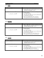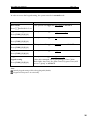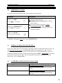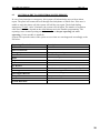
1
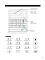
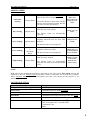
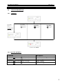
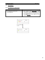
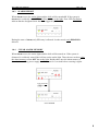
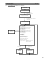
Security & Home Automation System AXI LED USER MANUAL (REV. 1.0) AX1 LED User Manual Rev 1.0 AX1 LED User Manual Rev 1.0 CONTENTS PREFACE 1 FEATURES 2 LED KEYPAD OUTLOOK 4 1.0 LIGHT INDICATION 6 CHAPTER 1: ALARM SYSTEM CONTROL 7 1.0 USING LED KEYPAD 1.0.1 1.0.2 ARMING 7 1.0.1.1 7 QUICK ARMING DISARMING 8 1.0.2.1 IN ARMED MODE 8 1.0.2.2 IN ALARM MODE 8 1.0.3 ALARM REPORT 9 1.0.4 CLEAR ALARM MEMORY 9 1.0.5 BYPASSING ZONE 1.0.5.1 1.1 7 QUICK BYPASSING ZONE ARM/DISARM USING TELEPHONE 10 10 11 1.1.1 ARM/DISARM WITH VOICE ACTIVE 11 1.1.2 ARM/DISARM WITH BEEPER 12 CHAPTER 2: HOME AUTOMATION CONTROL 13 2.0 INTRODUCTION 13 2.1 HOME AUTOMATION CONTROL USING LED KEYPAD 14 AX1 LED User Manual 2.2 HOME AUTOMATION CONTROL USING TELEPHONE Rev 1.0 15 2.2.1 WITH VOICE ACTIVE 15 2.2.2 WITH BEEPER 16 CHAPTER 3: VIEW TIMER MODE 17 CHAPTER 4: USER PROGRAMMING 18 4.0 PIN CODE EDIT 20 4.0.1 MASTER USER 20 4.0.2 USER 20 4.0.3 GUEST 21 4.0.4 DURESS 21 4.0.5 TIMER 22 4.0.5.1 IO ON 22 4.0.5.2 IO OFF 22 4.0.5.3 ARM 23 4.0.5.4 DISARM 23 4.0.6 CLOCK 23 4.0.7 INSTALLER ACCESS 24 4.0.8 FAST KEY ACCESS 24 4.0.9 PHONE LINE LOSS DETECTION 25 CHAPTER 5: KEYPAD SETTINGS 26 5.1 DOOR CHIME 26 5.2 KEYPAD SETTING VIEW 26 AX1 LED User Manual CHAPTER 6: WHEN THERE IS AN EMERGENCY Rev 1.0 27 6.0 EMERGENCY ALARM 27 6.1 DURESS ALARM (CALLING FOR HELP) 27 6.2 TAMPER LOSS AND PHONE LINE LOSS ALARM 27 6.3 SYSTEM ALERT TO USER THROUGH TELEPHONE 28 6.3.1 WITH VOICE ACTIVE 29 6.3.2 WITH BEEPER 30 CHAPTER 7: SYSTEM CHECKING 7.0 TROUBLE VIEW 7.0.1 QUICK TROUBLE VIEW 7.1 TESTING SYSTEM 31 31 31 32 7.1.1 LOCAL SYSTEM TEST (WALK TEST) 32 7.1.2 BELL TEST 32 7.1.3 MANUAL TEST REPORTING FOR CMS 32 7.1.4 BATTERY TEST 32 GLOSSARY 33 LIMITATIONS 34 SYSTEM INFORMATION 35 QUICK REFERENCE 37 AX1 LED User Manual Rev 1.0 PREFACE Thank you for selecting the new AX1 system. This manual will explain to you on how to operate your AX1 alarm and home automation system. This system is made up of a control panel, keypads, integrated switch module and telephone voice module. Specific areas of detections are called zones. Zones can be programmed to have different characteristics. Some zones may be 24-hour zones; they remain armed even when the alarm system is in disarm mode. (This setting is done during the installer programming as per user‟s request). In addition, some zones can be programmed by the users to allow zone bypassing. When you bypass a zone, the zone is temporarily removed from the alarm system. But always remember that bypassed zones are not protected. How your AX1 alarm and home automation system works? When a detection device is triggered, the zone indicator will light up. If the alarm system is armed, the control panel responds by reporting an alarm condition. The control of the system can be done either through keypad or telephone. If the alarm system is triggered, the signal can be transmitted to a central monitoring station (CMS). (Provided the AX1 system is connected to CMS) For safety purposes, the operation of the AX1 system requires the users to enter the personal identification number (PIN). User is advised to disable the installer access whenever necessary. (i.e. after the commissioning and servicing of alarm system.) 1 AX1 LED User Manual Rev 1.0 FEATURES AX1 LED 1. 8 fully programmable zones 2. Expandable up to 8 output controls (with feedback capability) 3. Supports up to 4 LED keypads 4. 1 Real time ARM/DISARM timer on Daily Basis only. 5. 4 Real time ON/OFF timer on daily basis 6. 7 user codes & 1 guest code 7. 3 Soft Zones (Emergency/Fire/Panic) 8. 2 Programming Mode- Installer Programming and User Programming 9. 5 User Arming type (Auto home arming/ Day arming/ Away arming/ Force arming/ Night arming) 10. Real time clock function 11. Programmable Entry/Exit Delay Time 12. 4 bell types (Steady/ Pulse/ Chirp/ Silent) 13. 3 zone types [End-of-line (EOL) / Normally Open (NO) / Normally Close (NC)] 14. Adjustable loop response sensitivity 15. Resetable auxiliary power supply upon Alarm Clearing 16. Key Switch function (Latch/ Momentary) 17. Dedicated Tamper zone 18. AC power supply monitoring 19. Low battery indication 20. Short circuit indication & protection 21. Bell Loss indication 22. Bell Test function 23. Telephone line loss detection 24. Programmable Event Reporting Code 25. Telephone Voice Module 26. RS485 ready (to support longer distance communication) 27. Report events to 4 phone numbers with 4 account numbers 28. Ademco® Contact ID CMS reporting format 29. Voice reporting format (direct to user) or tone reporting format 30. Interactive Voice menu or tone beepers during user call in 31. Support Remote programming via touch tone telephone 32. Programmable event trigger 2 AX1 LED User Manual Rev 1.0 33. Fast Key on Keypad for Easy menu access 34. Duress code 35. Walk test function 36. Double Call-in Feature for Fax Machine telephone line sharing 37. 16 Event Trigger Outputs with programmable countdown timer 3 LED KEYPAD OUTLOOK SYSTEM STATUS INDICATORS Power – Green Armed – Red Service – Yellow ZONE STATUS INDICATORS KEYPAD ACCESS Key Indication Auto-Home Arming / Testing Day Arming / Keypad Setting Night Arming / View Timer Fire Force Arming Home Automation Clear Alarm Memory Emergency Door Chime on/off View Trouble Zone Bypass Mode Panic Enter Command Cancel 4 AX1 LED User Manual Rev 1.0 ARMING MODE Arming Type Auto home Arming Zone Status Normal Status Information When To Use To arm the system with delay time in When user order for the user to exit the house To arm the system in delay time with the interior zone bypassed provided that the user does not leave the premises The perimeter zone is armed instantly while the user stays at home Day Arming Away Arming Normal Status Normal Status leaves the house and no one is at home. When user is at home. The interior zones are automatically bypassed To arm the system instantly through telephone when the user are away from the house. When user are outside. The interior zones are not bypassed Force Arming Normal Status or Abnormal Status To force arm the system instantly regardless of the zone status. The interior zones are not bypassed The perimeter zone is armed instantly while user stays at home. Night Arming Normal Status The interior zones are automatically bypassed. The delay zones become instant zones. When there are zone still open & user is at home. When everyone come back to home & user want to sleep. NOTE: Zone refers to the designated areas that are protected by the AX1 system. Zone status refers to the condition of the area. Normal status means door, window or detectors are in good/close condition. While abnormal status means the door/window may have been opened or the detector is not functioning. SOUND INDICATION Sound Indication Acceptance / Acknowledgement tone Description 2 fast beeps Error tone Entry delay Exit delay Door chime Continuous buzz for about 2 seconds Continuous beeping, fast beep for the last 10 sec Continuous slow beep, fast beep for the last 10 sec Continuous tone for about 2 seconds Alarm Chirp (1 second ON/ 4 seconds OFF) Pulse (2 seconds ON/ 2 seconds OFF) Continuous Tone Silent 5 AX1 LED User Manual Rev 1.0 LIGHT INDICATION No 1 2 3 4 5 6 7 8 9 Description Normal Mode Arming Home Automation Mode User Programming Mode AC power failure Trouble occurs View Trouble Mode Power * * Flash Armed OFF ON OFF Service *** *** Flash Zones Pending Pending Pending Flash Flash Flash Pending OFF * * ** ** ** ON ON Flash Pending Pending ON according to the type of trouble Zone Status (Triggered) (Bypassed) (Alarmed) * * * ** ** ** *** *** *** ON Flash Fast flash Tamper zone triggered * Fast flash *** Fast flash All zone‟s LEDs Fast flash Pending Flash Pending 10 * Fast flash Telephone line loss alarm triggered 11 Walk test * Flash AX1 LED Keypad Display’s Reference Table NOTE: * : When AC power ON, LED is ON; When AC power failure, LED is OFF ** : When armed, LED = ON When Emergency/Fire/Panic, LED = Flash When disarmed, LED = OFF *** : When trouble occurs, LED is ON; when no trouble occurs, LED is OFF Flash Fast flash : : 0.5 second ON, 0.5 second OFF 0.1 second ON, 0.1 second OFF KEYPAD NAVIGATION KEY FUNCTION [COM] Key : Command [#] Key : Enter [*] Key : Cancel 6 AX1 LED User Manual Rev 1.0 [CHAPTER 1] ALARM SYSTEM CONTROL 1.0 USING LED KEYPAD 1.0.1 ARMING Press [User PIN] and # Press [User PIN] and hold Press [User PIN] and hold [ [ ] for 2 sec. Exit delay starts to count down with sound. ] for 2 sec. Press [User PIN] and hold [ ] for 2 sec. System is now armed. 1.0.1.1 QUICK ARMING Command Press and hold the button [ ] for 2 seconds Information Auto Home Arming Press and hold the button [ ] for 2 seconds Press and hold the button [ ] for 2 seconds Day Arming Night Arming Press and hold the button [ ] for 2 seconds Force Arming 7 AX1 LED User Manual Rev 1.0 1.0.2 DISARMING 1.0.2.1 IN ARMED/ALARM MODE Command To disarm the system, press [User PIN] [#]. Information The keypad will beep twice upon confirmation. Otherwise, the error tone will sound if PIN numbers are entered wrongly. The ARMED light will go OFF once the system is disarmed. Press [User PIN] [#] to disarm System is now disarmed 8 AX1 LED User Manual Rev 1.0 1.0.3 ALARM REPORT When alarm occurs, the strobe lights and the bells will be turned ON. If the system is disarmed, it could only turn OFF the bell but not the strobe light. Zone LED fast flashes indicate that the designated zone has been triggered by alarm. During the state of alarm, only PIN entry is allowed. In other words, only DISARM is allowed. 1.0.4 CLEAR ALARM MEMORY When alarm occurs, the strobe lights and the bells will be turned on. If the system is disarmed, it could only turn off the bell but not the strobe light. Thus, the user needs to clear the alarm memory to turn OFF the strobe light. Besides that, once the alarm memory is cleared, the auxiliary power supply 1 will be reset for 3 seconds before restoring it again. Press and hold [ ] for 2 sec. Alarm Cleared 9 AX1 LED User Manual Rev 1.0 1.0.5 BYPASSING ZONE Bypassing a zone means removal of one or more protection zones from the system. In order to perform bypassing, the system must be in normal mode. Once the system is disarmed, the entire zone will be unbypassed. Press and Hold for 2 sec. Screen will show the current bypassed zone status. Zone LED turn ON to indicate zones are bypassed. To toggle ON/ OFF, press relevant zone number (1 to 8). Press to return back to normal mode. 1.0.5.1 QUICK BYPASSING ZONE Command Press and hold for 2 seconds Information Bypassing zone 10 AX1 LED User Manual 1.1 Rev 1.0 ARM/DISARM USING TELEPHONE The AX1 alarm system is designed with the feature which allow system control by using telephone, there are two methods. Firstly is using voice guided if voice module is installed into the system and secondly is guided by beeper. 1.1.1 ARM/DISARM WITH VOICE ACTIVE Welcome Please enter your code. Press [Master PIN] [ # ] within 1 minute Invalid Code Correct Code Incorrect code! Please enter your code Only 3 attempts allowed. System hangs up Press [0] Main Menu Press 1 for Security Menu 2 for Automation Menu 0 to Exit Press [1] You are not an authorized user. System will now exit. Press [0] System hangs up Security Menu Press 1 to ARM 2 to DISARM # for Main Menu 0 to Exit Press [#] Press [1] Thank you Arming Menu Press 1 to arm Partition 1 # for Main Menu 0 to Exit If wrong input key Invalid Input Press [0] * AX1 LED only support partition 1 Press [#] Press [1] If arming accepted, keypad shows: Press [0] Arming Mode Menu Press 1 for Auto Home Arming 2 for Night Arming 3 for Day Arming 4 for Away Arming 5 for Force Arming # for Main Menu 0 to Exit Press [#] Press [1] to [5] Press [0] Arming accepted. Press # for Main Menu 0 to Exit Press [#] 11 AX1 LED User Manual 1.1.2 Rev 1.0 ARM/DISARM WITH BEEPER (Without voice module) 5 Slow Tones Press [Master PIN] [#] within 1 minute Invalid Code Correct Code Error Tone (Long Beep) Acknowledgement Tone (Beep Twice) Only 3 attempts allowed. System Hangs up If arming accepted, keypad shows: Press [0] [#] To arm the system with Auto Home Arming, Press [1] [0] [1] [#] To arm the system with Away Arming, Press [1] [1] [1] [#] To arm the system with Day Arming, Press [1] [2] [1] [#] To arm the system with Night Arming, Press [1] [3] [1] [#] To arm the system with Force Arming, Press [1] [4] [1] [#] To DISARM Press [2] [1] [#] Invalid Code Error Tone (Long Beep) Correct Code Acknowledgement Tone (Beep Twice) 12 AX1 LED User Manual Rev 1.0 CHAPTER 2: HOME AUTOMATION CONTROL 2.0 INTRODUCTION The system can support up to 8 outputs and can be controlled during system in normal and armed state only. The outputs can be electrical appliances such as air-conditioners, fans or lights. The outputs can be configured as event-triggered outputs or normal outputs which are controlled either by LED keypad, real time clock timer or telephone remote control. Recommended air conditioner with memory backup or last state memory in Malaysia is as below: Wall Mounted Split Air Conditioner (Brand : Acson) Model: AWM101 – (1.0 HP) AWM151 – (1.5 HP) AWM201 – (2.0 HP) AWM251 – (2.5 HP) AWM301 – (3.0 HP) Ceiling Cassette Split Air Conditioner (Brand : Acson) Model: ACK15B – (1.5 HP) ACK20B – (2.0 HP) ACK25B – (2.5 HP) ACK30B – (3.0 HP) 13 AX1 LED User Manual 2.1 Rev 1.0 HOME AUTOMATION CONTROL USING LED KEYPAD Press and hold for 2 sec Zone LED will show the current output status. Press the relevant module number (1 to 8) to toggle output Zone LED turn ON to indicate outputs are on. Press [ 0 ] to ON all outputs Press [ 0 ] again to OFF all outputs Press to return back to normal mode. 14 AX1 LED User Manual 2.2 Rev 1.0 HOME AUTOMATION CONTROL USING TELEPHONE For home automation control by using telephone, there are two methods. One is using voice guided if voice module is installed into the system and secondly is guided by beepers. 2.2.1 WITH VOICE ACTIVE Welcome Please enter your code. Press [Master PIN] [#] within 1 minute Invalid Code Correct Code Incorrect code! Please enter your code Press [0] Main Menu Press 1 for Security Menu 2 for Automation Menu 0 to Exit Press [2] Thank you System hangs up Press [0] Automation Menu Press 1 to ON Output 2 to OFF Output 3 to ON ALL Output 4 to OFF ALL Output # for Main Menu 0 to Exit Press [#] Press [1] to [4] Press [0] Press 01 for Output 1 02 for Output 2 03 for Output 3 04 for Output 4 …… 08 for Output 8 # for Main Menu 0 to Exit Press [#] Press [x] [x] Press [0] (All) Output # is now ON /OFF Press # for Main Menu 0 to Exit Press [#] 15 AX1 LED User Manual Rev 1.0 2.2.2 WITH BEEPER (Without Voice Module) 5 Slow Tones Press [Master PIN] [#] within 1 minute Incorrect Code Correct Code Acknowledgement Tone (Beep Twice) Error Tone (Long Beep) To turn ON the output. Press [4] [Output Number] [#] To turn OFF the output. Press [5] [Output Number] [#] System Hangs up Press [0] [#] * Output Number - 01 to 08 - 00 for all outputs Invalid Code Error Tone (Long Beep) Correct Code Acknowledgement Tone (Beep Twice) 16 AX1 LED User Manual Rev 1.0 CHAPTER 3: VIEW TIMER MODE This feature enable user to view the timer that has been set earlier for Home Automation ON/OFF and also Auto ARM/ DISARM. Command Press [COM] [3] [1] [#] [1 – 4] [#] Information Home automation ON timer Press [COM] [3] [2] [#] [1 – 4] [#] Home automation OFF timer Press [COM] [3] [3] [#] Auto ARM timer Press [COM] [3] [4] [#] Auto DISARM timer Press [COM] [3] [1] [#] [1-4] [#] or [COM] [3] [2] [#] [1-4] [#] or [COM] [3] [3] [#] or [COM] [3] [4] [#] If timer was set, 4 digit timer will display one by one base on 24 hour format If timer was not set, all zone LEDs 1-9 will on 4 times Example: Timer ON 3.00pm (1500) Keypad will back to normal mode after show 4 digit timer 17 AX1 LED User Manual Rev 1.0 CHAPTER 4: USER PROGRAMMING Only user who has Master PIN can access to user programming mode. If there‟s any mistake made while programming or if the control panel rejects the command, keypad will sound an error tone and user has to re-enter the command again. There are 10 menus in user programming Edit Master PIN, User PIN and Guest PIN Master user can edit their existing Master PIN from this menu. User can edit or delete their existing PIN or create new PIN for other users from this menu. User can edit their access level from this menu. Guest can edit or delete their existing PIN from this menu. Guest can edit their access level and guest hour from this menu. The guest PIN is only valid when the guest time has not expired. User 1 – Master PIN, User 2 to 7 – User PIN, User 8 – Guest PIN Same PIN cannot be repeated to different user or guest. PINs can be set to 4 to 6 digits. Edit Duress Code User can edit or delete their existing duress code from this menu. CODE must be set in 4 digit, else error tone sound. Edit IO Module ON Timer This feature is to set the timer to turn ON the outputs automatically. Timer set must be in a 24 hour format. The system support 4 IO timers, so user can set 4 different time to turn ON the outputs. Keypad will arm if IO ON setting time reach. Edit IO Module OFF Timer This feature is to set the timer to turn OFF the outputs automatically. Timer set must be in a 24 hour format. The system support 4 IO timers, so user can set 4 different time to turn OFF the outputs. Edit Real Time Clock User can edit the real time clock from this menu. Time set must be in a 24 hour format. Edit Auto Arm Timer This feature enable user to set timer to auto Arm the system. Time set must be in a 24 hour format. Edit Auto Disarm Timer This feature enable user to set timer to auto Disarm the system. Time set must be in a 24 hour format. Installer Access Enabling or disabling the installer access. 18 AX1 LED User Manual Rev 1.0 Installer access will be disabling automatically every 3 hours. Fast Key Access Enabling or disabling the fast key access. Phone line loss detection Enabling or disabling the phone line loss detection. When in normal mode, press [Master PIN] [COM] [#] to enter user programming mode. To return to normal mode, press [COM] [#]. 19 AX1 LED User Manual 4.0 Rev 1.0 PIN CODE EDIT 4.0.1 MASTER USER Command Step 1: Press [1] [#] Information Zone 1 light will be ON to indicate that the command has been accepted and the users are in “Edit User’s PIN” option. Step 2: Enter the user number : [1] [#] User 1 = Master user Step 3: Press the new PIN : [4 - 6 digits PIN] [#] Zone light will be ON one by one to indicate that the PIN has been entered. Zone light will be ON one by one to indicate that the PIN has been entered. The keypad will beep twice for valid entry. Step 4: Repeat the new PIN: [4 - 6 digits PIN] [#] Note: PIN “000000” is not allowed to be used as password. Master PIN default value: “111111” 4.0.2 USER Command Step 1: Press [1] [#] Information Zone 1 light will be ON to indicate that the command has been accepted and the users are in “Edit User’s PIN” option. Step 2: Enter the user number : Step 3: Press the new PIN : [2 - 7] [#] User 2 - 7 = Normal user [4 - 6 digits PIN] [#] Zone light will be ON one by one to indicate that the PIN has been entered. Zone light will be ON one by one to indicate that the PIN has been entered. The keypad will beep twice for valid entry. Step 4: Repeat the new PIN: [4 - 6 digits PIN] [#] Step 5: Enter access level : [ Toggle key 1-4] [#] Press key 1 to key 4 to set user access level. Key [1] –Arm and Disarm On (1)/ Off (0) Key [2] – Arm (1)/ Disarm (0) Key [3] – Bypass Enable (1)/ Disable (0) Key [4 ] – Open/ Close Report (1)/ Disable (0) *By pressing Key 1- 4 will toggle its status to ON /OFF The keypad will beep twice for valid entry. Note: PIN “000000” is not allowed to be used as password. After enter the user number, press [#]. Press [0] [#] to delete PIN. The Master user should change the PIN for user 1 to 8 after the installation. Even though the user PIN is not used, the user should clear the PIN for those users by key with new PIN as “0”. 20 AX1 LED User Manual Rev 1.0 4.0.3 GUEST Command Step 1: Press [1] [#] Information Zone 1 light will be ON to indicate that the command has been accepted and the users are in “Edit User’s PIN” option. Step 2: Enter the user number : [8] [#] Step 3: Press the new PIN : [4 - 6 digits PIN] [#] Zone light will be ON one by one to indicate that the PIN has been entered. Zone light will be ON one by one to indicate that the PIN has been entered. The keypad will beep twice for valid entry. Step 4: Repeat the new PIN : [4 - 6 digits PIN] [#] Step 5: Enter access level : User 8 = Guest user [ Toggle key 1-4] [#] Press key 1 to key 4 to set user access level. Key [1] –Arm and Disarm On (1)/ Off (0) Key [2] – Arm (1)/ Disarm (0) Key [3] – Bypass Enable (1)/ Disable (0) Key [4] – Open/ Close Report (1)/ Disable (0) *By pressing Key 1- 4 will toggle its status to ON /OFF Step 6: Enter Guest Time : [0 - 15] [#] The keypad will beep twice for valid entry. Valid entry is 0 - 15 for number of days. The keypad will beep twice for valid entry. Note: - Pin “000000” is not allowed to be used as password. - After enter the user number, press [#]. Press [0] [#] to delete PIN. 4.0.4 DURESS Command Step 1: Press [2] [#] Information Zone 1 light will be ON to indicate that the command has been accepted and the users are in “Edit Duress’s Code” option. Step 2: Enter the Duress Code : [4 digits Code] [#] Zone light will be ON one by one to indicate that the PIN has been entered. The keypad will beep twice for valid entry. Note: - Duress Code default value: “2222” 21 AX1 LED User Manual Rev 1.0 4.0.5 TIMER 4.0.5.1 IO ON Command Step 1: Press [3] [#] Information Zone 1 light will be ON to indicate that the command has been accepted and the users are in “Edit IO ON Timer” option. Step 2: Enter the Timer Number: Timer 1 to Timer 4 Please enter international time according to the 24-hour format. E.g. “1400” for 2pm Zone light will be ON one by one to indicate that the time has been entered. Enter “0” will delete the I/O Module ON Timer. The keypad will beep twice for valid entry. [Timer number] [#] Step 3: Enter the IO ON Time: [ _ ] [ _ ] [ _ ] [ _ ] [#] 4.0.5.2 IO OFF Command Step 1: Press [4] [#] Information Zone 1 light will be ON to indicate that the command has been accepted and the users are in “Edit IO OFF Timer” option. Step 2: Enter the Timer Number : Timer 1 to Timer 4 Please enter international time according to the 24-hour format. E.g. “1400” for 2pm Zone light will be ON one by one to indicate that the time has been entered. Enter “0” will delete the I/O Module OFF Timer. The keypad will beep twice for valid entry. [Timer number] [#] Step 3: Enter the IO ON Time: [ _ ] [ _ ] [ _ ] [ _ ] [#] 22 AX1 LED User Manual Rev 1.0 4.0.5.3 ARM Command Step 1: Press [6] [#] Information Zone 1 light will be ON to indicate that the command has been accepted and the users are in “Edit Auto Arm Timer” option. Step 2: Enter the Auto Arm Time: [ _ ] [ _ ] [ _ ] [ _ ] [#] Please enter international time according to the 24-hour format. E.g. “1400” for 2pm Zone light will be ON one by one to indicate that the time has been entered. Enter “0” will delete the Auto Arm Timer. The keypad will beep twice for valid entry. 4.0.5.4 DISARM Command Step 1: Press [7] [#] Information Zone 1 light will be ON to indicate that the command has been accepted and the users are in “Edit Auto Disarm Timer” option. Step 2: Enter the Auto DisarmTime: [ _ ] [ _ ] [ _ ] [ _ ] [#] Please enter international time according to the 24-hour format. E.g. “1400” for 2pm Zone light will be ON one by one to indicate that the time has been entered. Enter “0” will delete the Auto Disarm Timer. The keypad will beep twice for valid entry. 4.0.6 CLOCK Command Step 1: Press [5] [#] Information Zone 1 light will be ON to indicate that the command has been accepted and the users are in “Edit Real Time Clock” option. Step 2: Edit Real Time Clcok: [ _ ] [ _ ] [ _ ] [ _ ] [#] Please enter international time according to the 24-hour format. E.g. “1400” for 2pm Zone light will be ON one by one to indicate that the real time clock has been entered. The keypad will beep twice for valid entry. 23 AX1 LED User Manual Rev 1.0 4.0.7 INSTALLER ACCESS Command Step 1: Press [8] [#] Information Zone 1 light will be ON to indicate that the command has been accepted and the users are in “Installer Access” option. Step 2: Press key [1] to toggle the ON/OFF (Enable/Disable) of Installer Access Zone light 1 will toggle ON/OFF according to Installer Access setting status. Step 3: Press [#] Keypad will beep twice for valid entry Note: Initially Installer Access will be toggling ON (Enable). Installer access will be disabling automatically after 3 hours. Indication Light ON means features ENABLED, OFF means DISABLED. Due to security reason, user is advised to disable installer access once the system is hand over. User should keep installer accessibility barred all the time unless requested by installer during commissioning or servicing. 4.0.8 FAST KEY ACCESS Command Step 1: Press [9] [#] Information Zone 1 light will be ON to indicate that the command has been accepted and the users are in “Fat Key Access” option. Step 2: Press key [1] to toggle the ON/OFF (Enable/Disable) of Fast Key Access Zone light 1 will toggle ON/OFF according to Fast Key Access setting status. Step 3: Press [#] Keypad will beep twice for valid entry Note: Initially Fast Key access will be toggling ON (Enable). When Fast Key disable, arming mode and bypass mode only can be access by PIN code. Fast Key setting is an individual keypad setting. Indication Light ON means features ENABLED, OFF means DISABLED. 24 AX1 LED User Manual Rev 1.0 4.0.9 PHONE LINE LOSS DETECTION Command Step 1: Press [10] [#] Information Zone 1 light will be ON to indicate that the command has been accepted and the users are in “Phone Line Loss Detection” option. Step 2: Press key [1] to toggle the ON/OFF (Enable/disable) of Phone Line Loss Detection Zone light 1 will toggle ON/OFF according to Phone Line Loss Detection setting status. Step 3: Press [#] Keypad will beep twice for valid entry Note: Initially phone line loss detection will be toggling OFF (Disable). When phone line loss detection enable and phone communication option enable in installer programming, alarm will be trigger if phone line cut off. Indication Light ON means features ENABLED, OFF means DISABLED. 25 AX1 LED User Manual Rev 1.0 CHAPTER 5: KEYPAD SETTINGS In order to access the keypad setting, the system must be in normal mode. Command Door Chime Press Information This options will toggle the door chime to ON/OFF and hold for 2 sec Keypad Back Light This options will toggle the keypad back light to ON/OFF Press [COM] [2] [1] [#] Arm Tone This options will toggle the arm tone to ON/OFF Press [COM] [2] [2] [#] Pre-warn Tone This options will toggle the pre-warn tone to ON/OFF Press [COM] [2] [3] [#] Key press Tone This options will toggle the key press tone to ON/OFF Press [COM] [2] [4] [#] Toggle ON/OFF for all keypads setting Press [COM] [2] [5] [#] This option will toggle all keypad settings all at one time. Under this command, all keypad settings ( Door Chime, Back light, Arm Tone, Pre-warn Tone, Key press Tone) will act as a “group” to ON/OFF. Note: Initially keypad setting will be all toggling ON (Enable). Keypad will beep twice for valid entry. 26 AX1 LED User Manual Rev 1.0 CHAPTER 6: WHEN THERE IS AN EMERGENCY 6.0 EMERGENCY ALARM In order to access this function, the system must be in normal mode Command If there is a „FIRE‟ Press for 2 seconds If there is a „EMERGENCY‟ Press for 2 seconds Information Alarm will be triggered ARMED LED will flash indicate soft zone alarm trigger. A message will be sent to the Central Monitoring Station (CMS) An alert tone or voice reporting will be sent through telephone If there is a „PANIC‟ Press for 2 seconds To OFF the emergency alarm alert, press [USER PIN] [#] 6.1 DURESS ALARM (CALLING FOR HELP) In the event where the user is forced by an intruder or robber to disarm the alarm system, user can disarm the alarm system by using Duress Code. By pressing Duress Code, user can access the menu to disarm the system. At the same time, a silent signal will be sent to any designated telephone number or central monitoring station (CMS) to call for help.(* Provided the system is connected to CMS). The siren and strobe will not be activated. To set the duress code, refer to section 4.0.4 6.2 TAMPERED AND PHONE LINE LOSS ALARM Reporting / Zone indication Tampered Alarm Phone Line Loss Alarm Description ARMED and all zone LED will fast Blink to indicate the alarm was triggered by the tamper switch. ARMED and SERVICE LED will fast Blink to indicate the alarm was triggered by the phone line loss. 27 AX1 LED User Manual 6.3 Rev 1.0 SYSTEM ALERT TO USER THROUGH TELEPHONE In case of any intrusion or emergency, this system will acknowledge users with an alarm report. The panel will contact the user through fixed telephone or mobile line. If the user is unable to reply the phone call, this system will call the user again. The default dialing attempts are 5 times. After 30 minutes, the system will call again. The number of repetition calls after 30 minutes depend on the redial attempt set in the installer programming. The reporting comes in two reporting method – no voice or beeper reporting and voice reporting (if voice module is installed). System will report the status of the system to user when an event happened accordingly to the list below: Reporting / Zone indication Zone xx Violated Zone xx Restored Emergency Fire Panic Help AC Loss AC Restore Trouble Zone Bypass Zone Bypass Restore Tamper System Armed System Disarmed Description Zone has been violated Alarm in zone xx has been restored Emergency occurring Fire occurring Panic occurring Duress Code has been entered AC loss AC restored Trouble due to battery problem and bell problem Zone has been bypassed Zone has been unbypassed Tamper occurring System has been armed System has been disarmed 28 AX1 LED User Manual 6.3.1 Rev 1.0 WITH VOICE ACTIVE Answer Call Slow Beeps Press any key to acknowledge system System hangs up Press [0] Thank you Press [1] Security Menu 1 to ARM # for Main Menu 0 to Exit System Violated Press 1 for Security Menu 2 for Automation Menu 3 for System Status 0 to Exit Press [3] Press [2] Automation Menu Press 1 to ON Output 2 to OFF Output 3 to ON ALL Output 4 to OFF ALL Output # for Main Menu 0 to Exit Zone 1 Violated Zone 7 Violated Emergency ………… # for Main Menu 0 to Exit Zone Indication/ Reporting Refer 1.1.1(page 11) Refer 2.2.1 (page 14 ) 29 AX1 LED User Manual Rev 1.0 6.3.2 WITH BEEPER (Without Voice Module) Answer Call Slow Beeps Press any key to acknowledge system Continuous tone with different frequency of 0.5 seconds Press any key within 1 minute to acknowledge 5 slow tones (System Acknowledged) System Hangs up Press [0] [#] To arm the system with Auto Home Arming, Press [1] [0] [1] [#] To arm the system with Away Arming, Press [1] [1] [1] [#] To arm the system with Day Arming, Press [1] [2] [1] [#] To arm the system with Night Arming, Press [1] [3] [1] [#] To arm the system with Force Arming, Press [1] [4] [1] [#] To DISARM Press [2] [1] [#] To turn ON the output. Press [4] [Output Number] [#] To turn OFF the output. Press [5] [Output Number] [#] * [Output Number] - 01 to 08 for output 1 to 8 - 00 for all outputs Invalid Code Error Tone (Long Beep) Correct Code Acknowledgement Tone (Beep Twice) 30 AX1 LED User Manual Rev 1.0 CHAPTER 7: SYSTEM CHECKING 7.0 TROUBLE VIEW System must be in normal or armed mode in order to view trouble. Control panel will monitor a number of possible trouble conditions. If one of these conditions occurs, the SERVICE light will turn ON and remain ON until trouble free and/or it receives clearance instruction from the users. There are only 8 conditions available designated by indication lights (1 to 8, indication light 9 will remain OFF all the time). 7.1.1 QUICK TROUBLE VIEW Command To view the trouble condition: Press and hold for 2 sec To Exit View Trouble mode Information The service light will FLASH to indicate that keypad is under View Trouble Mode. Designated zone light is used to reflect the type of problem. (Refer to table below) The service light will be ON if the trouble conditions still remain. The designated zone light will be restored back to the actual zone‟s status. Press [#] Trouble DC Loss (Low Battery) Display Zone 1 LED turn on Causes Backup battery in weak or backup battery is not available. Bell Strobe Siren Loss Zone 2 LED turn on Either bell, strobe or siren is loss. External Communication Error Zone 3 LED turn on Unable to call out either due to no reply by user during reporting. Internal Communication Error Zone 4 LED turn on LED keypad and IO Expander cannot communicate with control panel due to main panel or connection failure. Short Circuit Zone 5 LED turn on One or more of the part in AP1, AP2, AP3, BELL, SL, SIREN port is short circuit. Tamper Zone 6 LED turn on Tamper occurred and has not been cleared by alarm memory clear Phone Line Loss Zone 7 LED turn on No phone line connected to the system AC Loss Zone 8 LED turn on No power supply detected 31 AX1 LED User Manual 7.1 Rev 1.0 TESTING SYSTEM Users are advised to test the system frequently. System must be tested at least once every three months. If the system is not functioning accordingly, please contact the nearest dealer for technical assistance. In order to test , system must be on normal mode. There are 4 types of tests: walk test, bell test, CMS test and battery test. 7.1.1 LOCAL SYSTEM TEST (WALK TEST) Command Initiate Walk Test Press [COM] [1] [1] [#] To exit, press any key. Information Walk test allow on-site testing for each zone of the system The keypad will beep twice upon confirmation The SERVICE and ARMED light will FLASH to indicate that the system is currently under the Walk Test. Each time zone faulted, corresponding zone light will fast flash and keypad will chime until system exit walk test. The keypad will beep twice upon confirmation. Back to normal mode. 7.1.2 BELL TEST Command Test bell or siren Press [COM] [1] [2] [#] Information Once command has been acknowledged, the keypad and bell will sound continuously for 3 seconds. 7.1.3 MANUAL TEST REPORTING FOR CMS Command Manual test reporting for CMS Press [COM] [1] [3] [#] Information The keypad will beep twice upon confirmation. Panel will generate message to CMS. 7.1.4 BATTERY TEST Command Test back-up battery Press [COM] [1] [4] [#] Information Battery test takes few seconds The keypad will beep twice or reject tone as a result. The indication of low battery can be seen from View System Trouble Mode. 32 AX1 LED User Manual Rev 1.0 GLOSSARY Arming/Disarm To ARM is to ON the alarm system and to DISARM is to OFF the alarm system Battery A back up power source to provide protection for a limited time in the event of a power failure Bypass Removal of one or more protection zones from the system Central Monitoring Station (CMS) Central control station to receive the alarm message from AX1 system Chime A beeping tune from the keypad to indicate sensor is activated Duress Code In the event that you are forced by an intruder to disarm your system, you disarm the system with the Duress Code which will cause the system to disarm and simultaneously send a silent distress signal to the central monitoring station (CMS). Default duress code is 2222. Entry Delay The amount of time that you are allowed to enter the premises when the system is armed. Exit Delay The amount of time that you are allowed to leave the premises when the system is arming. Guest PIN A temporary four to six digit code which is used to arm and disarm the system from the keypad User PIN A four to six digit code which is used to arm and disarm the system from the keypad Master PIN A four to six digit code which can be used to program, reprogram and erase user codes, as well as arming and disarm the system from the keypad. The Master PIN is also equivalent to user 1 PIN. Default Master PIN is 111111. Zone An area which is protected by a security device. Your front door may be designated as Zone 1, while the living room motion detectors maybe designated as Zone 2. Refer to the Zone Label on your keypad for the Zone Identification of your system. The designated zone number is set during installer programming. 33 AX1 LED User Manual Rev 1.0 LIMITATIONS Even though AX1 is an advanced security system, it does not 100% guarantee protections against burglary, fire or other losses. Any alarm system whether commercial or residential is subject to compromise or failure-to-warn for a variety of reasons. These include: Intruders may gain access through unprotected openings or have the technical sophistication to bypass an alarm sensor or disconnect an alarm warning device. Intrusion detectors, smoke detectors and many sensing devices will not operate without power. Devices powered by AC will not work if there is no AC power supply for any reason and their back up batteries are missing, dead or improperly installed. Alarm warning devices such as sirens or bells may not alert people or wake up sleeper if they are located on the other side of closed or partly closed door. Telephone lines needed to transmit alarm from the premise to a central monitoring station may be out or temporarily out of service. Telephone station lines are subjected to compromise by sophisticated method of attack. Smoke detector used in conjunction with the alarm system may not sense fires that start where smoke cannot reach the detector such as wall, roof or the other side of the door. Smoke detector also may not sense a fire on another level of residence or carelessness and safety hazards like smoking in the bed, violent explosions, escaping gas, improper storage of flammable material, overloaded electrical circuits, and children playing with matches. The most common cause of an alarm system not functioning properly when an intrusion or fire occurs is inadequate maintenance. Therefore, your system should be tested weekly to ensure all sensors are working properly. Installing an alarm system may make you eligible for lower insurance rates but an alarm system is not substitute for insurance. Homeowners, property owners and renters should continue to insure their lives and properties. Note: Specifications subject to change without prior notice. 34 AX1 LED User Manual Rev 1.0 SYSTEM INFORMATION MASTER USER: ADDRESS: TELEPHONE NUMBER: DATE : REMARKS : Telephone Number 1 Receiver Number 1 Receiver Type Receiver Pattern CMS Account Number 1 User / CMS Permanent / Backup Telephone Number 2 Receiver Number 2 Receiver Type Receiver Pattern CMS Account Number 2 User / CMS Permanent / Backup Telephone Number 3 Receiver Number 3 Receiver Type Receiver Pattern CMS Account Number 3 User / CMS Permanent / Backup Telephone Number 4 Receiver Number 4 Receiver Type Receiver Pattern CMS Account Number 4 User / CMS Permanent / Backup Telephony Settings Dial Attempt Redial Attempt Number of Rings before answer times times rings 35 AX1 LED User Manual Rev 1.0 Zone Settings Zone Zone Type 1 2 3 4 5 6 7 8 Light/Interior/Instant/Delay/24 Hours Light/Interior/Instant/Delay/24 Hours Light/Interior/Instant/Delay/24 Hours Light/Interior/Instant/Delay/24 Hours Light/Interior/Instant/Delay/24 Hours Light/Interior/Instant/Delay/24 Hours Light/Interior/Instant/Delay/24 Hours Light/Interior/Instant/Delay/24 Hours Zone Chime Yes/No Yes/No Yes/No Yes/No Yes/No Yes/No Yes/No Yes/No Output Map Description Output Settings Output 1 2 3 4 5 6 7 8 Output Description Output Timers Timer Timer 1 Timer 2 Timer 3 Timer 4 Timer ON Date: Time: Date: Time: Date: Time: Date: Time: Timer OFF Date: Time: Date: Time: Date: Time: Date: Time: Output No. Arm/Disarm Timers Timer Timer 1 Timer ARM Date: Time: Timer DISARM Date: Time: System Timers Entry Delay Timer Exit Delay Timer Bell Audible Time Seconds Seconds Minutes 36 AX1 LED User Manual Rev 1.0 QUICK REFERENCE 1) To arm the house & other Fast Key Functions Key press 1 and hold 2s 2 and hold 2s 3 and hold 2s 4 and hold 2s 5 and hold 2s 6 and hold 2s 7 and hold 2s 8 and hold 2s 9 and hold 2s and hold 2s Option Auto Home Arming mode Day Arming Mode Night Arming Mode Force Arming Automation Mode Clear alarm memory Chime mode Service mode Bypass zone Emergency Alarm Remark When you leave the house When you are at home day time When you goto Sleep When there are zone still open Control Lighting Menu Stop Strobe light To off zone sound in keypad To check system for service To ignore this zone from security To trigger Emergency alarm and hold 2s Fire Alarm To trigger Fire alarm and hold 2s Panic Alarm To trigger Panic alarm 2) To Disarm the house 1. [ PIN CODE ] + [#] 3) To stop the bell, siren and strobe light when alarm trigger 1. 2. 3. [ PIN CODE ] + [#] Check the alarm report for violated zone. Clear alarm by pressing [6] and hold for 2 second to resume to normal status (Strobe light will turn off) 3) When the system call to report 1. 2. 3. 4. 5. Pick up the call Press any key to acknowledge system. Press “3” to listen to system reporting. Follow the interactive menu. Once done with the reporting and control, press [0] + [#] to hang up 4) When you call in to the system 1. 2. 3. 4. Wait for the ring count Once system accept the call, press [MASTER PIN CODE] + [#] Follow the interactive menu Once done the control, press [0] + [#] to hang up 37