1
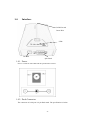
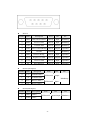
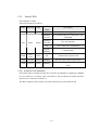
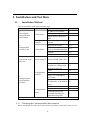
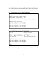
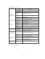
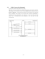
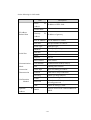
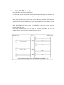
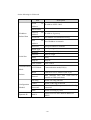
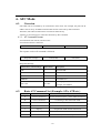
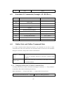
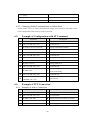
EZL-300S User’s Manual
Version 1.2
Sollae Systems Inc.
To all residents of the European Union
Important environmental information about this product
This symbol on this unit or the package indicates that disposal of this unit after its
lifecycle could harm the environment. Do not dispose of the unit as unsorted municipal
waste; it should be brought to a specialized company for recycling. It is your responsibility to
return this unit to your local recycling service. Respect your local environmental regulation. If in
doubt, contact your local waste disposal authorities.
-2-
-Table of Context 1.
OVERVIEW..................................................................................................................... - 6 -
1.1.
OVERVIEW ......................................................................................................................- 6 -
1.2.
COMPONENTS..................................................................................................................- 7 -
1.3.
SPECIFICATIONS ..............................................................................................................- 7 -
1.4.
INTERFACE ......................................................................................................................- 8 -
1.4.1.
Power ............................................................................................................................ - 8 -
1.4.2.
Dsub Connector ............................................................................................................ - 8 -
1.4.3.
Status LEDs ................................................................................................................. - 10 -
1.4.4.
wireless LAN Interface ................................................................................................ - 10 -
2.
INSTALLATION AND TEST RUN ............................................................................. - 11 -
2.1.
INSTALLATION METHOD ................................................................................................- 11 -
2.1.1.
Checking the Communication Environment................................................................ - 11 -
2.1.2.
Configuration wireless LAN ........................................................................................ - 12 -
2.1.3.
Connecting to the Network.......................................................................................... - 12 -
2.1.4.
Configuring the Environmental Variables ................................................................... - 12 -
2.2.
TEST RUN......................................................................................................................- 13 -
2.2.1.
Changing PC IP Address............................................................................................. - 13 -
2.2.2.
Installing EZL-300S .................................................................................................... - 13 -
2.2.3.
Configuring EZL-300S ................................................................................................ - 13 -
2.2.4.
Connecting to the PC Serial Port................................................................................ - 14 -
2.2.5.
Communication Test .................................................................................................... - 14 -
3.
CONFIGURING WIRELESS LAN, IP ADDRESS, AND ENVIRONMENTAL
VARIABLES ........................................................................................................................... - 15 3.1.
CONFIGURATION WIRELESS LAN ..................................................................................- 15 -
3.1.1.
Items to Check for the Wireless LAN........................................................................... - 15 -
3.1.2.
Setting Wireless LAN Items of the EZL-300S .............................................................. - 17 -
3.2.
IP ADDRESS AND ENVIRONMENTAL VARIABLES ............................................................- 19 -
3.3.
CONFIGURATION BY EZCONFIG .....................................................................................- 23 -
3.3.1.
ezConfig Menus........................................................................................................... - 23 -
3.3.2.
Example configuration of ezConfig............................................................................. - 25 -
3.4.
CONFIGURATION USING TELNET ...................................................................................- 26 -
3.4.1.
Example of Configuration using Telnet....................................................................... - 27 -
3.4.2.
Configuration Commands by telnet............................................................................. - 30 -
-3-
3.5.
AT COMMAND...............................................................................................................- 31 -
3.6.
SETTING IP ADDRESS BY ARP.......................................................................................- 31 -
3.6.1.
Setting of EZL-300S’s IP address in Windows............................................................. - 32 -
3.6.2.
Setting of EZL-300S’s IP address in Linux .................................................................. - 32 -
3.7.
SETTING IP ADDRESS-RELATED ITEMS BY DHCP.........................................................- 33 -
4.
OPERATION MODE.................................................................................................... - 34 -
4.1.
OPERATION MODE OVERVIEW ......................................................................................- 34 -
4.1.1.
Overview ..................................................................................................................... - 34 -
4.2.
HOW TO INITIATE EACH OPERATION MODE ..................................................................- 34 -
4.2.1.
How to Initiate Normal Mode ..................................................................................... - 34 -
4.2.2.
How to Initiate Console Mode..................................................................................... - 34 -
4.2.3.
.How to Initiate ISP Mode........................................................................................... - 35 -
4.2.4.
Comparison of Operation Modes ................................................................................ - 35 -
4.3.
NORMAL COMMUNICATION MODE ................................................................................- 35 -
4.4.
CONSOLE MODE............................................................................................................- 36 -
4.5.
ISP MODE .....................................................................................................................- 36 -
5.
NORMAL COMMUNICATION MODE .................................................................... - 39 -
5.1.
T2S (TCP TO SERIAL)...................................................................................................- 39 -
5.2.
ATC (AT COMMAND)....................................................................................................- 41 -
5.3.
COD (CONNECT ON DEMAND) .....................................................................................- 43 -
5.4.
U2S (UDP TO SERIAL)..................................................................................................- 45 -
6.
ATC MODE ................................................................................................................... - 47 -
6.1.
OVERVIEW ....................................................................................................................- 47 -
6.1.1.
AT command format .................................................................................................... - 47 -
6.2.
BASIC AT COMMAND SET (EXAMPLE: ATA, ATD ETC.) ................................................- 47 -
6.3.
EXTENDED AT COMMANDS (EXAMPLE: AT+PLIP ETC.) ...............................................- 48 -
6.4.
ONLINE STATE AND ONLINE COMMAND STATE .............................................................- 48 -
6.4.1.
Changing Online State to Online Command State ...................................................... - 48 -
6.4.2.
Changing Online Command State to Online State ...................................................... - 49 -
6.5.
EXAMPLE OF CONFIGURATION WITH AT COMMAND......................................................- 49 -
6.6.
EXAMPLE OF TCP CONNECTION ...................................................................................- 49 -
6.6.1.
Example of Active Connection .................................................................................... - 49 -
6.6.2.
Example of passive Connection................................................................................... - 50 -
6.7.
EXAMPLE OF TCP DISCONNECTION ..............................................................................- 50 -
-4-
6.7.1.
Example of active disconnection ................................................................................. - 50 -
6.7.2.
Example of passive disconnection............................................................................... - 50 -
7.
OTHER FUNCTIONS................................................................................................... - 51 -
7.1.
SSL...............................................................................................................................- 51 -
7.2.
PING TEST .....................................................................................................................- 51 -
7.3.
DESIGNATING TCP TX BLOCK ......................................................................................- 51 -
7.4.
SETTING COD DELAY IN COD MODE ...........................................................................- 52 -
7.5.
MULTI-CONNECTION .....................................................................................................- 52 -
7.6.
DEBUGGING ..................................................................................................................- 52 -
8.
TECHNICAL SUPPORT, WARRANTY, AND NOTES ON OPERATION............. - 53 -
8.1.
TECHNICAL SUPPORT ....................................................................................................- 53 -
8.2.
WARRANTY ..................................................................................................................- 53 -
8.2.1.
Refund ......................................................................................................................... - 53 -
8.2.2.
Free Repair Services ................................................................................................... - 53 -
8.2.3.
Charged Repair Services............................................................................................. - 53 -
8.2.4.
Notes on Operation ..................................................................................................... - 53 -
9.
REVISION HISTORY .................................................................................................. - 55 -
-5-
1. Overview
1.1.
Overview
Along with the development of the Internet, the demand for data communication
functions has increased recently. Data communication over the Internet requires using
TCP/IP, the Internet communication protocol. That is to say, in order to connect a
system to the Internet, TCP/IP protocol must be implemented. It is possible to
implement TCP/IP by directly implementing the protocol, porting public TCP/IP, or
using Operating System (OS). However, all these methods impose burdens on the
developer in time, cost, and technology.
ezTCP series, a Serial ↔ TCP/IP protocol converter product group of Sollae Systems,
enables you to use TCP/IP communication (the Internet communication) function simply
by “connecting the cable to a serial port”. ezTCP sends data from the serial port to the
Internet network after TCP/IP processing, and vice versa.
EZL-300S in ezTCP product group is a product that provides TCP/IP communication
through wireless LAN. In other words, like other ezTCP products, EZL-300S sends data
from the serial port to the wireless LAN after TCP/IP processing and vice versa.
As supporting RS-422, and RS485 as well as RS-232 for serial ports, EZL-300S can be
connected to various systems. It provides DHCP function, so that it can be applied to the
cable network and the xDSL network.
As EZL-300S provides SSL security function, it can be used in a system that requires a
high level of security.
-6-
1.2.
Components
z
EZL-300S Body
z
5V Power Adopter (Option)
z
RS232C cable for PC connection (Option)
z
PCMCIA Card (Option)
1.3.
Specifications
Power
5V (±10%)
Current
340mA typical
Dimension
136mm x 83mm x 29mm
Weight
About 140g
Interface
Serial Port
Serial
9pin Dsub male
Network
IEEE802.11b (PCMCIA card required)
RS232 / RS422(full duplex) / RS485 (half duplex)
(1200bps ~ 115200bps)
Network
IEEE802.11b
Protocols
TCP, UDP, IP, ICMP, ARP, DHCP, SSL 3.0 / TLS 1.0
Communicati
on Mode
Utilities
)
Input Voltage
T2S
TCP Server Mode
COD
TCP Client Mode
TCP Server/Client
ATC
(AT command emulation)
U2S
UDP
ezConfig
Configuration utility via LAN
ezSerialConfig
Configuration utility via serial port
ezterm
Socket test utility
hotflash
Firmware download utility via TFTP
You can download free utilities and firmware from http://www.eztcp.com.
-7-
1.4.
Interface
PCMCIA card
Insert Hole
LEDs
DC Jack
9pin-Dsub
1.4.1. Power
DC 5V is used for EZL-300S and the specification is below:
1.4.2. Dsub Connector
The connector of serial port is 9 pin Dsub male. The specification is below:
-8-
z
RS-232
number name
description
level
Dir.
Etc.
1
DCD
Data Carrier Detect
RS232
Input
Mandatory
2
RXD
Receive Data
RS232
Input
Mandatory
3
TXD
Transmit Data
RS232
Output Mandatory
4
DTR
Data Terminal Ready
RS232
Output
Optional
5
GND
Ground
Ground
-
Mandatory
6
DSR
Data Set Ready
RS232
Input
Optional
7
RTS
Request To Send
RS232
Output
Optional
8
CTS
Clear To Send
RS232
Input
Optional
9
RI
Ring Indicator
RS232
Input
Optional
z
RS-422 (full duplex)
number name
description
level
9
TX+
Transmit Data +
1
TX-
Transmit Data -
4
RX+
Receive Data +
3
RX-
Receive Data -
z
Dir.
Etc.
Differential Output
Mandatory
Differential
Input
RS-485(half duplex)
number
name
description
9
TRX+ Data +
1
TRX-
Data -
level
Dir.
Etc.
Differential Input/Output Mandatory
-9-
1.4.3. Status LEDs
EZL-300S has 5 LEDs.
Each LED functions as follows:
Name Meaning
PWR
Power
Color
LED
Status
Description
Red
ON
Power is supplied.
Blinking
IP is allocated but TCP connection is not
for a Sec
established.
Blinking 4
STS
Status
Yellow
IP is not allocated.
Times/Sec
ON
TCP connection is established.
Rapidly
Console mode
Blinking
LINK
LAN
Link
Green
ON
Connected to wireless LAN
There are data on the wireless LAN
RXD
LAN Rx
Yellow
Blinking
TXD
LAN Tx
Green
Blinking
Packets are being transmitted to wireless
LAN
1.4.4. wireless LAN Interface
EZL-300S requires a PCMCIA 16bit PC card. The card should be compliant to PRISM.
(If you would use a wireless LAN card which is not provided from Sollae Systems,
please test or contact me in advance.)
The MAC address of EZL-300S is in bottom of the body, not in PCMCIA card.
- 10 -
2. Installation and Test Run
2.1.
Installation Method
You can install EZL-300S in the following steps.
Title
1.
Checking the
communication
environment
Item
Check items
Configuration
method
2.
Configuration
wireless LAN
3.
Connecting to the
network
4.
Configuring the
environmental
variables
Check items
Check method
Configuration
method
Configuration
items
Sub-item
Description
IP address environment
3.
Serial port settings
Application program to be
used
ezSerialConfig
console
Infrastructure/ad-hoc
SSID
(Service Set Identification))
Channel
WEP
3.
5.
3.1.
3.1.1.
3.1.1.
3.1.1.
3.1.1.
Check if LINK LED is ON.
Set by ezConfig, a utility
program for configuration
through the network.
telnet
console
Set by AT commands in
ATC mode
By arp
(Temporarily set IP address
only)
IP address related items
Serial port related items
Communication mode
(Decided depending on
application program)
3.3.
3.4.
4.4.
6.
3.6.
3.1.
3.1.
5.
5. Application to the field
2.1.1. Checking the Communication Environment
Before installing EZL-300S, check the network environment where EZL-300S is to be
- 11 -
installed, including the followings matters:
z
Wireless LAN type(Infrastructure/adhoc)
z
Wireless LAN SSID, channel
z
WEP and WEP key
z
IP address environment (local IP, subnet mask, gateway, etc.)
z
Serial port type of the equipment to which EZL-300S is going to be connected
(RS232, RS422, RS485)
z
Serial port items of the equipment to which EZL-300S is going to be
connected (baud rate, data bit, parity, stop bit)
z
Application program protocol to be used (TCP/UDP, server/client, SSL, etc.)
)
For application program protocol to be used, see “5. Normal Communication
Mode”.
2.1.2. Configuration wireless LAN
Before using the EZL-300S, the user must set wireless LAN-related items. Wireless
LAN-related items can be set via ezSerialConfig or console in a Console mode. Supply
power without the PCMCIA card insertion to enter into Console mode. In the Console
mode, the user can set not only wireless LAN-related items but also all setup values of
the EZL-300S.
2.1.3. Connecting to the Network
Insert the PCMCIA card while power is not supplied. Then, connect the device with the
EZL-300S using RS232 cable that is compliant with the specification, and supply
power. After power is supplied, the link LED should be turned on. When the link
LED is on, it means that a link has been established between the AP and wireless LAN
device or between the wireless LAN devices to enable communication between them.
2.1.4. Configuring the Environmental Variables
When network connection is completed, configure the environmental variables such as
IP address related items, serial port related items, and communication mode related
items through the LAN using “ezConfig,” the environmental variable configuration
program.
)
For environmental variable configuration, see “3. Configuring wireless LAN,
IP Address and Environmental Variables.”
- 12 -
2.2.
Test Run
You can perform test run according to the following orders. The test run described here
is based on the assumption that the IP address of the PC is set to 10.1.0.2 and its serial
interface is configured as RS232 interface.
2.2.1. Changing PC IP Address
You can change the IP address of your PC as follows:
IP Address
10.1.0.2
Subnet Mask
255.0.0.0
Gateway IP Address 0.0.0.0
2.2.2. Installing EZL-300S
Connect the AP with the PC through the crossed LAN cable.(When connecting through
a hub, use a one-to-one cable for this connection.) After installing the cable, supply
power to the AP as provided by the AP vendor. After supplying power, check the link
LED indicating a connection between the AP and PC to make sure this connection is
successfully made.
2.2.3. Configuring EZL-300S
Configure EZL-300S setting using ezConfig, the ezTCP configuration program, as
follows.
Run ezConfig, and click [Search ezTCP] button in the ezConfig window. And, ezConfig
program will search all ezTCPs on the local network.
When ezTCP is searched, MAC address of the ezTCP is displayed on the [Search List]
window (The MAC address is indicated at the bottom of the product case).
Select the corresponding MAC address, and set the same as shown in the following
figure and click [Write] button to save the settings.
- 13 -
.
2.2.4. Connecting to the PC Serial Port
Connect the serial port of your PC and that of EZL-300S, using the supplied serial
communication cable. Then, run serial communication program such as Hyper Terminal
and Teraterm. When the program is run, select the same serial port values as those set to
EZL-300S [19200bps, data bit: 8 bits, stop bit: 1 bit, no parity], which will finish the
preparation for serial communication.
2.2.5. Communication Test
When the preparation for serial communication is finished, enter the following in the
DOS window on your PC, to connect to TCP through Telnet program.
"Telnet 10.1.0.1 1470"
When TCP connection succeeds, STS LED of EZL-300S turns ON.
When the STS LED turns ON, enter “123” on the Telnet window, and "123" will appear
on the hyper terminal. Enter “ABC” on the hyper terminal, and “ABC” will appear on
the Telnet window. Otherwise, communication test fails.
- 14 -
3. Configuring wireless LAN, IP Address, and
Environmental Variables
3.1.
Configuration wireless LAN
When configuring the wireless LAN, the user must check the network type and security
issues of the network currently being used or to be installed in the future.
3.1.1.
z
Items to Check for the Wireless LAN
Network Type (infrastructure/ad-hoc)
The infrastructure is a network connection mode that allows communication between
wireless LAN devices or between the wireless LAN and the wired LAN (Ethernet)
through the Access Point (AP). When a network type is set to infrastructure,
communication with wired LAN via AP is possible, which allows both wired and
wireless Internet communications.
<Infrastructure>
The ad-hoc network is designed to communicate between wireless LANs without any
- 15 -
AP. Since communication is established without any AP, the user cannot access an
external network or the Internet. This is also called a peer-to-peer mode.
<Ad-hoc>
z
Service Set Identifier (SSID)
When configuring a network, the user can configure different networks using different
APs. In this case, the SSID is used to differentiate one network from another. In other
words, when configuring an infrastructure network, the user can make communication
with the AP which he/she wants to communicate with by setting the SSID of the desired
AP in the EZL-300S. (See 3.1.2.) For information about SSID of the AP, AP manual or
AP configuration program can be referred to. If the user did not set the SSID, the EZL300S will be connected with the AP that is first found when power is supplied.
The maximum length of the SSID is 32 bytes, and the user can use ASCII code to set the
SSID.
z
Channel
The channel is communication path in the network that it belongs to. Channel values
are set as the same value with the AP.
- 16 -
z
Wired Equivalent Privacy (WEP)
This is about security of the wireless LAN. The wireless LAN provides similar security
to that of the wired LAN using the WEP. To use the WEP, the user must set the key
value. According to the key value, data is encoded in 64 bits or 128 bits for
communication. If the user did not set the WEP, security-related problems may occur.
3.1.2. Setting Wireless LAN Items of the EZL-300S
There are two ways to configure wireless LAN-related items - Windows
utility "ezSerialConfig" and via console.
The following table describes each configuration field.
Field
TARGET
SSID
Description
Factory-set
SSID of the Network to Participate
Not set.
CREATE
SSID of the Network to Newly Create When Configuring
SSID
an Ad-hoc Network
Not set.
0) IBSS: Ad-hoc Network
CC TYPE
1) BSS: Infrastructure Network
2) WDS: Reserved (Reserved)
1
3) Pseudo IBSS: Reserved (Reserved)
CHANNEL
Channel number
0
0) WEP is not used.
WEP TYPE
0
1) 64 bit WEP key
2) 128 bit WEP key
KEY ID
z
Number of the Key to be Used
0
Setting via ezSerialConfig utility
① After connecting EZL-300W without PC card to COM port of PC via a serial cable,
Turn on the EZL-300W.
② Execute ezSerialConfig.
③ After selecting COM port in ezSerialConfig, press [READ]. If you press [READ]
button, The configuration values of EZL-300W will be shown.
④ After inputting configuration value what you want, Press [WRITE] button. The
configuration values will be saved into the EEPROM area of EZL-300W.
- 17 -
z
Setting via console
When entering into Console mode, enter "env wlan" and set fields relating to the
wireless LAN.
If the user presses the Enter key in a field without entering any key, the user will use the
existing value in the field. When the user completes entering data, the EZL-300S is
reset to restart operation.
The user can enter "." to delete existing values when setting the SSID.
☞ For more information about Console mode, see "4. Operation Mode."
msh>env wlan
TARGET SSID (APAIR): SOLLAE
CREATE SSID ( no SSID ):
0 - IBSS
1 - BSS
2 - WDS
3 - Pseudo IBSS
CC TYPE (1):
CHANNEL (0):
0 - disable WEP encryption
- 18 -
1 - select 64bit WEP key
2 - select 128bit WEP key
WEP TYPE (1):
KEY0 - 4e dc 58 80 15
KEY1 - 00 00 00 00 00
KEY2 - 00 00 00 00 00
KEY3 - 00 00 00 00 00
EDIT KEY
:1
KEY0 - 4e dc 58 80 15
KEY1 - 11 22 33 44 55
KEY2 - 00 00 00 00 00
KEY3 - 00 00 00 00 00
EDIT KEY
:
select default WEP key id
KEY ID
(0): 1
updating eeprom...done.
<Example of Configuring the Wireless LAN>
3.2.
IP Address and Environmental Variables
For TCP/IP communication, you must set IP address related items. In addition, you have
to set serial port related items (serial port type, communication speed, data bit length,
parity bit, flow control, etc) to EZL-300S.
You can set the IP address and the serial port related items by using ezConfig, the
supplied configuration utility which allows you to configure your EZL-300S over the
network, by logging in Telnet, or by using AT commands in ATC mode. Also, you can
set IP address temporarily, using ARP method which uses MAC address (hardware
address).
IP Address-related
Items
Item
Local IP
Address
Subnet Mask
Gateway IP
Address
Description
Local Port
Port number for waiting to be connected
in Server mode
IP address of EZL-300S
Subnet mask
IP address of gateway
- 19 -
Port number for waiting UDP data
IP address to connect in Client mode
IP address to send data in UDP mode
Port number to connect in Client mode
Port number to send data in UDP mode
Peer IP
Address
Peer Port
Serial Port
Communication Mode
Serial Type
Serial port type(RS232,RS422,RS485)
Baud Rate
Serial port speed (bps)
Data Bits
Data bit length
Parity
Parity
Stop Bit
Stop bit
Flow Control
Flow control
ezTCP Mode
Communication mode
COD
DELAY
Timeout
ezConfig
Minimum number of bytes attempting to
connect/transmit
Reconnect time when COD connection
is closed (unit: seconds)
Limit time to keep connection
Enable ezConfig function.
Telnet
Enable Telnet log in function
Password
Select between Telnet password and
ezConfig password.
ARP
Enable IP setting by ARP.
DHCP
Select to receive EZL-300S IP address
as DHCP.
SSL
Enable SSL security feature.
SEND
DEALY
TCP data transmission interval
(unit: ms)
Conn. Byte
Connect/Disconnect
Event
Configuration Method
Used
Flexible IP
Other Functions
z
Comment
User comment on the product
Multi Conn.
Multi-connection at T2S
Local IP Address
IP address of EZL-300S. If you set DHCP is set, an IP address is automatically allocated.
So, you cannot set the local IP address.
z
Subnet Mask
Sets subnet mask of the network where EZL-300S is installed
- 20 -
z
Gateway IP Address
Sets the gateway IP address of the network where EZL-300S is installed.
z
Local Port
Port number, which is used as TCP port number waiting to be connected when EZL300S operates as TCP server or as the port number waiting for UDP data when it
operates in U2S communication mode.
z
Peer Port
Local port number of the server to connect when EZL-300S operates as TCP client or to
transmit UDP data when it operates as U2S
z
Serial Type
Selects a serial port interface of EZL-300S, among RS232, RS422 (full duplex), and
RS485 (half duplex) interfaces.
z
Baud Rate
Selects a serial port speed (1200 bps ∼ 115200bps).
z
Data Bits
Selects a data bit length of the serial port (7 bits or 8 bits)
z
Parity
Select a parity bit of the serial port (None, Even, Odd).
z
Stop Bit
Selects a stop bit length of the serial port (1 bit, 2 bits).
z
Flow Control
Selects flow control for the serial port (None, RTS/CTS, Xon/Xoff).
z
ezTCP Mode
Selects the communication mode of EZL-300S (T2S, ATC, COD, U2S).
z
Conn. Byte
Decides a point of time to start connection when EZL-300S operates as COD. EZL-300S
- 21 -
starts to connect to the host (Peer IP Address and Peer Port) of the designated host upon
receiving as many data as specified by [Conn. Byte] from the serial port.
z
Block (Byte)
Decides the size of UDP packet to be sent at a time when EZL-300S operates as U2S.
z
COD Delay – Possible to set using Telnet (See 3.3).
Time after connection is off as Conn. Byte is 0 in COD mode until connection is
reestablished (unit: second)
z
Timeout
When EZL-300S operates as TCP such as T2S, COD and ATC, connection is closed if
data communication is not continued as long as the time set to this item unless this item
is set to 0 (unit: second)
z
Interval
When EZL-300S operates as UDP like U2S, it transmits data in blocks by gathering data
for the time set to this item (unit: 10ms)
z
ezConfig
You can use ezConfig utility only this item is enabled.
(If this item is not enabled, you cannot set EZL-300S using ezConfig. Therefore, it is
recommended to enable this all the times.)
z
Telnet
Only when this item is enabled, you can log in Telnet, to control or check EZL-300S
through the EZL-300S console.
z
Password
Sets a password for configuring with ezConfig or logging with Telnet.
z
ARP
Sets whether to or not to set IP address using ARP protocol. When this item is selected,
EZL-300S uses the destination IP address of the first packet coming to its MAC address
as its own IP address temporarily.
- 22 -
z
DHCP
Set to receive an IP address as DHCP.
z
SSL – Possible to set using Telnet (See 3.4)
Enabled when SSL is used.
z
Send Delay - Possible to set using Telnet (See 3.4)
Sets the time to gather data from the serial port, when transmitting TCP data (unit: ms,
minimum setting: 20). If this item is set to 0, the send delay works as 20ms.
z
Comment
Stores maximum 32 byte user comment on the product. This item helps the user
distinguish each EZL-300S more easily.
z
Multi Conn.
Enabled to support maximum 8 multiple connections in T2S mode. All connected hosts
can exchange data with each other.
3.3.
Configuration by ezConfig
3.3.1. ezConfig Menus
The basic environmental variables (IP address related items, serial port items, and etc.) can
be set by ezConfig which is an integrated management tool for Windows.
ezConfig is operated in Microsoft Windows(Windows 98, 98 SE, 2000 Pro, ME, XP
Pro/Home). Following is the screen shot of ezConfig which is just launched.
- 23 -
√ ezConfig can set not only EZL-300S’s environmental variables but also other ezTCP
series.
The functions of ezConfig’s buttons are followed:
This button is used to search for all of the network-attached ezTCPs. The search results
will be displayed on the [Search List] box and you can select an item using a mouse or
cursor as required. The value displayed on the box indicates the MAC ADDRESS of
each ezTCP. The selected setup value of ezTCP will be displayed on the right side.
You can see only the ezTCP configuration values if you press this
button after entering the 6-digit hexadecimal number printed on the ezTCP main body in
the MAC ADDRESS box. It is useful when there are too many ezTCPs attached to the
network to search for one from the LIST box.
This button is used to save the changed value in ezTCP after modifying
the configuration. Make sure not to press this button during operating ezTCP since
ezTCP will automatically be reset right after its environment setup value is saved.
Otherwise, it may cause malfunction.
- 24 -
This button is used to close ezConfig. You can also close it by pressing
ESC key on the keyboard.
ezTCP provides User Authentication function to prevent an unwanted
person from modifying the configuration. The authentication process is performed
through the password string verification. When entering or changing the password
strings, you can use this button. Changing the ezTCP configuration details if a password
has been entered requires the proper password to be entered in the PASSWORD field.
√ If you forget the password, erase or reenter in Console Mode.
This button is used to read a dynamic status during operating ezTCP.
Pressing this button will display a new window, where the time-elapsed after the power
is on, the current IP address, and the data throughput of the serial port are indicated.
Double-clicking each item on the [Search List] will carry out the same function.
3.3.2. Example configuration of ezConfig
ezConfig can be used to change the IP address related items, the serial port setup value,
the serial port operation mode, and how to setup ezTCP. This section describes these
functions briefly. For more information, see the following sections.
The following example shows how to read and change ezTCP's basic functions. Try
changing ezTCP setup value according to the following sequence:
z
When the ezTCP power is turned on and the LAN cable is connected correctly,
pressing [Search] or [Read] button will display the following window:
z
If a network-attached ezTCP is detected, the following message will be
displayed. If a message pops up indicating that there is no response from ezTCP,
check that the power is turned on and the cable is connected correctly, then try
- 25 -
pressing [Search] or [Read] button.
√ It is impossible to use ezConfig, if EZCFG check box is disabled. This function can be
re-enabled in Console mode.
z
If more than one ezTCP are detected, ezTCP's MAC ADDRESS will be
displayed in the [Search List] box on ezConfig. Check if the MAC ADDRESS
displayed in the [Search List] window corresponds to that printed on ezTCP
main body. The following screen shows this process:
z
Set [ezTCP Mode], [Local IP Address], [Local Port], and serial port related items.
After setting press [Write] button. If there is any error during writing process, check
the LAN between PC and EZL-300S.
z
Check if the set IP address is correct with ping command in DOS prompt.
Following is the message if the IP address is OK. If "Request timed out" message is
shown, check IP address.
C:\>ping a.b.c.d
Pinging a.b.c.d with 32 bytes of data:
Reply from a.b.c.d: bytes=32 time=1ms TTL=64
Reply from a.b.c.d: bytes=32 time=1ms TTL=64
Reply from a.b.c.d: bytes=32 time=1ms TTL=64
Reply from a.b.c.d: bytes=32 time=1ms TTL=64
<When IP address is a.b.c.d.>
√ IP address, subnet mask, and gateway IP address of both PC and EZL-300S should be
correct to succeed in ping test.
3.4.
Configuration using Telnet
- 26 -
You can configure the environmental variables for Telnet connection, using Telnet client
in your Windows or Linux or using a terminal like Teraterm Pro.
.
√ If Telnet checkbox in ezConfig items is not checked, you cannot log in Telnet. To
use Telnet function, enable Telenet function in console mode or using ezConfig
program.
3.4.1. Example of Configuration using Telnet
The following section describes the process of configuring the environmental variables
using Telnet.
The environment used here for an example is as follows.
z
PC
EZL-300S
Operating System
Windows XP Korean
-
Application
Telnet
-
Local IP Address
10.1.0.2
10.1.0.1
Subnet mask
255.0.0.0
255.0.0.0
Gateway IP address
10.1.0.254
10.1.0.254
Click “Run” in the Start menu of Windows, and the Run window appears.
Enter “cmd” in the Run window (If the OS is Windows 98, enter “command”).
z
Then, the DOS window appears. Enter “Telnet 10.1.0.1” in the DOS window,
and click “Enter”.
.
- 27 -
z
When the following message is displayed, Telnet connection is successfully
established.
z
If a password has been set to EZL-300S, Telnet connection is established only
when the password is entered.
z
The following is a screen for setting the IP address related items.
- 28 -
z
The following is a screen for setting the serial port related items and the TCP
port related items.
z
The following is a screen for setting SSL and other items.
z
The following is a screen for setting a password.
- 29 -
3.4.2. Configuration Commands by telnet
command
Item
MAC ADDR
env if
Fixed
EZCFG
Enable ezConfig function.
ARP
Enable IP setting by ARP.
DHCP
LOCAL IP
SUBNET MASK
env ezl
Description
Select to receive EZL-300S IP address as
DHCP.
IP address of EZL-300S
Subnet mask
GATEWAY
IP address of gateway
BAUD RATE
Serial port speed (bps)
PARITY
DATA BITS
Parity
Data bit length
RTSCTS
Flow control
TELNET
Enable Telnet log in function
MUX TYPE
Communication Mode
(0: T2S, 1: ATC, 2: COD, 3: U2S)
T2S, ATC, COD: Limit Time to Keep Connection
TIME OUT
(unit: 10ms)
U2S: UDP data receiving time from serial port for a
block (unit: 10ms)
LOCAL PORT
Local Port Number
COD: Minimum number of bytes attempting to
WATER MARK
connect(unit: byte)
U2S: UDP block size (unit: byte)
PEER IP
T2S: connection permitted peer IP address
(when 0.0.0.0, any host can connect)
- 30 -
COD: IP address to connect in Client mode
U2S: UDP datagram destination IP address
PEER PORT
env pwd
ATC, COD: connection port nmber
U2S: UDP datagram destination Port number
Password for telnet login and ezConfig. For erasing, input ‘.’.
COMMENT
SSL
env ext
SEND DELAY
COD DELAY
User specific information(maximum: 32bytes)
Enabling SSL function
TCP data transmitting time
(unit: ms)
Reconnection time when disconnected in COD
Mode. (unit: second)
√ If any item is modified, the item is saved and reboot automatically.
√ After setting IP address successfully by telnet but IP address is not set correctly, turn off
ARP function.
3.5.
AT command
In ATC mode, the user can set environment variables through the serial port using AT
command.
)
3.6.
For more information, See “6. ATC Mode”.
Setting IP address by ARP
If ARP function is enabled, EZL-300S saves the destination IP address of the first packet
which incomes to its MAC address as its local IP address to its volatile memory. By using
this function, user can set IP address of EZL-300S.
On Windows and UNIX(Linux) platform, the command 'arp' enables a user to change
the contents of arp cache table from the host computer. After changing the contents of
the arp cache table, attempting a Telnet connection or a ping test will change the EZL300S's IP address. IP address changed by the arp command will not be stored in
EEPROM. Therefore, the user should change the IP-related items by giving "env if"
command through telnet access. EZL-300S allows the user to change the IP address
only one time after the power is turned on.
- 31 -
The example listed below shows how to change the arp cache table on Windows' MSDOS prompt window and Linux. If EZL-300S's Ethernet address is 00:30:f9:00:00:01
and the IP address to use is a.b.c.d., the user can change the IP address as follows:
3.6.1. Setting of EZL-300S’s IP address in Windows
C:\>arp -s a.b.c.d 00-30-f9-00-00-01
☜ modifying table
C:\>arp -a
☜ confirming modification
Interface: xxx.xxx.xxx.xxx on Interface xxxxxxxx
Internet Address
a.b.c.d
Physical Address
00-30-f9-00-00-01
Type
static
C:\>ping a.b.c.d
☜ ping test (after resetting EZL-300S)
Pinging a.b.c.d with 32 bytes of data:
Reply from a.b.c.d: bytes=32 time=1ms TTL=64
Reply from a.b.c.d: bytes=32 time=1ms TTL=64
Reply from a.b.c.d: bytes=32 time=1ms TTL=64
Reply from a.b.c.d: bytes=32 time=1ms TTL=64
C:\>
3.6.2. Setting of EZL-300S’s IP address in Linux
rtos:~>arp -s a.b.c.d 00:30:f9:00:00:01 ☜ modifying table
rtos:~>arp
Address
a.b.c.d
☜ confirming modification
HWtype HWaddress
ether
FLags Mask Iface
00:30:f9:00:00:01
rtos:~>ping a.b.c.d
CM
eth0
☜ ping test (after resetting EZL-300S)
Pinging a.b.c.d with 32 bytes of data:
Reply from a.b.c.d: bytes=32 time=1ms TTL=64
Reply from a.b.c.d: bytes=32 time=1ms TTL=64
Reply from a.b.c.d: bytes=32 time=1ms TTL=64
Reply from a.b.c.d: bytes=32 time=1ms TTL=64
rtos:~>
√ Modified IP address store its new IP address to its volatile memory, so user should login
and change IP address if you would change IP address permanently.
- 32 -
3.7.
Setting IP Address-related Items by DHCP
Under environment with a network operating a DHCP server, DHCP protocol allows
the user to automatically set the IP address, subnet mask, gateway, and name server of
EZL-300S. Using DHCP automatic setup function requires the user to check [DHCP]
item on ezConfig. Note that the user may have to check [ARP] item according to the
type of DHCP servers.
- 33 -
4. Operation Mode
Operation Mode Overview
4.1.
4.1.1. Overview
EZL-300S has three modes - Normal mode, Console mode, and ISP mode. Normal
mode is the data communication mode operating in the normal state. In Console mode,
the user can set environment variables (especially variables relating to the wireless
LAN) through the serial port. In ISP mode, the user can download firmware to operate
the EZL-300S.
4.2.
How to Initiate Each Operation Mode
4.2.1. How to Initiate Normal Mode
If power is supplied with the PCMCIA card inserted, the EZL-300S operates in Normal
mode. When the EZL-300S enters into Normal mode, the EZL-300S attempts a
wireless LAN connection, and the link LED is turned on after wireless LAN LINK
connection is established.
)
For more information, see “5. Normal Communication Mode.”
4.2.2. How to Initiate Console Mode
Connect the serial port of the EZL-300S with the PC or notebook computer, and execute
a serial communication program (for example, Hyper Terminal). Then, supply power
without the PCMCIA card inserted to enter into Console mode. After power-up EZL300S will enter into console mode in 2-3 seconds.
Console mode operates at 19200 bps. When entering into Console mode, the following
message is displayed:
- 34 -
4.2.3. How to Initiate ISP Mode
Connect the serial port of EZL-300S to a PC or a notebook, run serial communication
program (Teraterm, etc.) using which you can send binary data, and then configure the
serial port as follows: 115200 bps, 8 data bits, no parity, 1 stop bit, no flow control.
Supply power to EZL-300S with ISP jumper-ON inner of the product, and EZL-300S
operates in ISP mode. The following is the message displayed on the serial terminal
when EZL-300S is connected to the serial port in ISP mode.
4.2.4. Comparison of Operation Modes
The following table is the comparison of the above described operation modes.
Mode
PCMCIA
Card
Normal Inserted
ConsoleRemoved
ISP
4.3.
Description
Baud-Rate
Data Communication Mode In the Normal State
T2S, ATC, COD, U2S
set by the user
Environment Variables through the Serial Port
19200 bps, N, 8,
(by ezSerialConfig or console(hypher terminal)
1
115200 bps, N, 8,
Removed Firmware Download Mode
1
Normal Communication Mode
Normal communication mode is suitable for the purpose of using EZL-300S.
Normal communication mode can be classified into four modes – T2S, ATC, COD, and
U2S – each of which is described in the following table.
Communication
Mode
Protocol
Connection
Need for User
Configuration of
Equipment
Environmental
Software
Variables through
- 35 -
Topology
T2S
TCP
ATC
TCP
COD
TCP
U2S
UDP
Passive
Connection
Active/Passive
Connection
Active
Connection
No Connection
Modification
Serial Port
Not needed
Impossible
1:1
Needed
Possible
1:1
Not needed
Impossible
1:1
Not needed
Impossible
N:M
TCP protocol requires connection process. The connection is always established as 1:1
connection. At this time, the host waiting for connection (passive connection) is called a
server and the one attempting to connect (active connection) is called a client.
On the other hand, UDP communicates by block unit without connection process. As UDP
does not require connection, numbers of hosts can communicate at the same time.
)
4.4.
For more information on communication modes, refer to the next chapter.
Console Mode
In console mode, you can configure the environmental variables of EZL-300S and all
security functions are disabled. Therefore, whether you choose or not, ezConfig and
Telnet functions are enabled. If you have lost your password, you can remove or change
the password in this mode.
Communication Speed 19200 bps
Parity Type
no parity
Data Bits
8 bits
Stop Bit
1 stop bit
)
Commands used in console mode are the same as those set after logging in
Telnet. So, refer to “3.4 Configuring using Telnet”.
4.5.
ISP Mode
In ISP mode, you can download the latest firmware (EZL-300S operation software)
provided by our company.
- 36 -
Communication Speed 115200 bps
Parity Type
no parity
Data Bits
8 bits
Stop Bit
1 stop bit
The following section describes how to download firmware in ISP mode.
z
Set the serial terminal through which you can transmit binary data as shown
above, and connect the supplied serial cable. Supply power to EZL-300S with
ISP jumper-ON in inside of EZL-300S. Then, the following message is displayed
on the serial terminal.
z
Enter the program command ‘p’, and press the Enter key. Then, the following
message is displayed.
z
Firmware to be downloaded is transmitted. The following is a screen displayed
when the firmware is normally transmitted to EZL-300S and saved in its flash
memory without an error.
- 37 -
z
When downloading is completed, turn off the power and then turn it on again.
- 38 -
5. Normal Communication Mode
5.1.
T2S (TCP To Serial)
In T2S mode, the EZL-300S functions as a server.
When a host connect to predefined local port, the EZL-300S accepts a TCP
connection. When the EZL-300S accepts TCP connection, then the TCP connection is
established. After connection is established, TCP/IP processing is performed on the
data coming to the serial port, which is then transmitted to the remote host. And the
TCP/IP data coming from the remote host is TCP/IP-processed and transmitted to the
serial port to establish data communication. (Data coming to the serial port before TCP
connection is established will be ignored.)
To limit the peer host, user should set [Peer IP Address]. The only pre-defined host can be
accessible. If [Peer IP Address] is 0.0.0.0, any host can connect to EZL-300S.
If Multi Conn. Function is enabled, Maximum 8 hosts connect to EZL-300S. All hosts which
are connected communicate with EZL-300S.
- 39 -
Set the following for T2S mode:
Item
Local
Description
IP
Address
Subnet mask
Subnet Mask
IP Address Relate Gateway
Items
IP
Address
Communication
Mode
IP address of gateway
Peer IP Address
Port number for waiting to be connected
in Server mode
Permitted host to connect
(if set to 0.0.0.0, any host can connect)
Serial Type
Serial port type
Baudrate
Serial port speed (bps)
Data bits
Data bit length
Parity
Parity
Stop bit
Stop bit
Flow Control
Flow control
ezTCP Mode
Communication Mode (T2S(0))
SSL
Enabling SSL function
Local Port
Serial Port
IP address of EZL-300S
Multiple connection up to 8
Multi Conn.
(SSL is not supported when Multi Conn.
Is enabled)
Timeout
Limit time to keep connection
ezConfig
Enable ezConfig function.
Configuration
Telnet
Enable Telnet log in function
Method
Password
Select between Telnet password and
ezConfig password.
ARP
Enable IP setting by ARP.
DHCP
Select to receive EZL-300S IP address
as DHCP.
Disconnection
Dynamic IP
- 40 -
5.2.
ATC (AT Command)
In ATC mode, the user can control the EZL-300S in a similar way to controlling the
modem using AT command. In ATC mode, only a TCP connection is possible and both
the server and the client can be configured.
In ATC mode, the AT command allows the user to set environment variables including
the IP address and control TCP connection and disconnection.
- 41 -
Set the following for ATC mode.
Item
Description
Local IP Address IP address of EZL-300S
Subnet mask
Subnet Mask
Gateway
IP Address
Relate Items
Serial Port
IP
Address
IP address of gateway
Local Port
Port number for waiting to be connected in
Server mode
Peer IP Address
Peer IP address to connect
Peer Port
Peer port number to connect
Serial Type
Serial port type
Baudrate
Serial port speed (bps)
Data bits
Data bit length
Parity
Parity
Stop bit
Stop bit
Flow Control
Flow control
Communication ezTCP Mode
Communication mode(ATC(1))
Mode
SSL
Enabling SSL function
Disconnection
Timeout
Limit time to keep connection
ezConfig
Enable ezConfig function.
Configuration
Telnet
Enable Telnet log in function
Method
Password
Select between Telnet password and
ezConfig password.
ARP
Enable IP setting by ARP.
DHCP
Select to receive EZL-300S IP address as
DHCP.
Dynamic IP
)
See “6. ATC Mode.”
- 42 -
5.3.
COD (Connect On Demand)
In COD mode, the EZL-300S functions as a client.
When data of the pre-specified size [CONN BYTE] comes to the serial port, the EZL300S attempts a TCP connection to the TCP port [PEER PORT] of the preset host IP
[PEER IP ADDRESS]. If the remote host accepts the TCP connection, TCP connection
will be established. Data coming to the serial port after connection establishment is
TCP/IP-processed and transmitted to the remote host. And, data coming from the
remote host is TCP/IP-processed and transmitted to the serial port for data
communication.
- 43 -
Set the following for COD mode.
Item
Local
Description
IP
Address
Subnet mask
Subnet Mask
IP Address
Gateway
Related Item
IP address of EZL-300S
IP
Address
IP address of gateway
Peer IP Address
Peer IP address to connect
Peer Port
Peer port number to connect
Serial Type
Serial port type
Baudrate
Serial port speed (bps)
Data bits
Data bit length
Parity
Parity
Stop bit
Stop bit
Flow Control
Flow control
Communication
ezTCP Mode
Communication mode(COD(2))
Mode
SSL
Enabling SSL function
Connection/
Conn. Byte
Bytes for starting to connect
Disconnection
Timeout
Limit time to keep connection
ezConfig
Enable ezConfig function.
Telnet
Enable Telnet log in function
Password
Select between Telnet password and
ezConfig password.
ARP
Enable IP setting by ARP.
DHCP
Select to receive EZL-300S IP address as
DHCP.
Serial Port
Configuration
Method
Dynamic
Address
IP
- 44 -
5.4.
U2S (UDP To Serial)
U2S mode allows for UDP communication.
In UDP mode, data are transmitted in blocks, which requires dividing data coming to the
serial port into blocks before transmitting data. A procedure for dividing data into
blocks is as follows:
If data of pre-specified bytes [Conn. Byte] comes to the serial port of the EZL-300S or if
a specified period of time [TIMEOUT] elapses after first data reception, all data received
for the same period is recognized as one block which is then transmitted to the
UDP. The [TIMEOUT] unit is 10ms. If [TIMEOUT] is set to 2, the time period is
between 20ms and 30ms.
Since UDP communication does not require a connection procedure, the user can
establish N-to-M communication via multicast and broadcast.
√ SSL protocol cannot be used in U2S, because SSL works over TCP.
- 45 -
Set the following for U2S mode.
Item
.
Local
Description
IP
Address
Subnet mask
Subnet Mask
IP address
Related Item
Gateway
Communication
Mode
Packets
IP address of gateway
Port number for UDP data receving
Local Port
Address
Serial Port
IP
Address
Peer
IP address of EZL-300S
IP
Peer IP address to transmit
Peer Port
Peer port number to transmit
Serial Type
Serial port type
Baudrate
Serial port speed (bps)
Data bits
Data bit length
Parity
Parity
Stop bit
Stop bit
Flow Control
Flow control
ezTCP Mode
Communication mode(U2S(3))
Block
UDP block size to transmit (unit: byte)
Interval
Data gathering time from serial port to
transmit as UDP (unit:10ms)
ezConfig
Enable ezConfig function.
Configuration
Telnet
Enable Telnet log in function
Method
Password
Select between Telnet password and ezConfig
password.
ARP
Enable IP setting by ARP.
DHCP
Select to receive EZL-300S IP address as
DHCP.
Dynamic IP
- 46 -
6. ATC Mode
6.1.
Overview
EZL-300S can be controlled by AT commands in ATC mode. For example, the peer host IP
address can be set by AT+PRIP command and connect to the host by ATD command.
Therefore, EZL-300S communicates several hosts alternatively.
And also, it provides passive connection function by ATA command.
6.1.1. AT command format
AT commands start with AT, and end <CR>.
AT command format is followed.
AT
Command
<CR>(0x0d)
The response code to AT command is followed.
Response message
<CR>(0x0d)
<LF>(0x0a)
Response Message
6.2.
When ATV1 (initial setting)
When ATV0
Description
OK
0
command OK
CONNECT
1
TCP connected
NO CARRIER
3
TCP disconnected
ERROR
4
Command error
Set value
Set value
When query set value
(example: AT+PRIIP?)
Basic AT Command Set (Example: ATA, ATD etc.)
Command
Function
Description
A
passive connection
Listen connection (host → EZL-300S connection)
D
active connection
Connecting to host form EZL-300S
E
echo
H
off-hook
disconnection
I
Inquery
Output EZL-300S related-information
O
Online
To online mode
V
enable result code
Result code (numeric-V0, alphabetic-V1)
Echo (E0 - no echo, E1-echo)
- 47 -
Z
6.3.
6.4.
reset
Reset
Extended AT Commands (Example: AT+PLIP etc.)
Command
Function
Description
+PLIP
local IP address
+PSM
subnet mask
+PGIP
default router
+PLP
listening TCP port
+PTO
timeout
+PRIP
Remote machine IP address
+PRP
Remote machine TCP port
+PWP
Write configuration
Saving and Reset
+PRC
ezConfig enable/disable
ON: 1, OFF: 0
+PARP
ARP setting function enable/disable
ON: 1, OFF: 0
+PDC
DHCP enable/disable
ON: 1, OFF: 0
Online State and Online Command State
It is online command mode during disconnected. AT commands can be used in online
command mode. After TCP connection, AT commands cannot be used. To use AT commands
during the connection, change state to online command state.
Online
Command
State
Online State
During TCP disconnected, AT commands can be used
To use AT commands during the connection, required escape
sequence
During TCP connected, all serial data to EZL-300S convert TCP
and send to ethernet
6.4.1. Changing Online State to Online Command State
To change online state to online command state during the connection, +++ string should be
transmitted to EZL-300S as following time interval.
When transmitting +++ string to EZL-300S, +++ string will be sent to peer host.
The time from final data the first ‘+’ data of
No data over 500ms(guard time)
- 48 -
‘+++’ string
time intervals between ‘+’s
0~500ms
Time interval after receiving last ‘+’
No data over 500ms (guard time)
6.4.2. Changing Online Command State to Online State
If EZL-300S’s state is in online command state during TCP connection, EZL-300S’s state
can be changed into online state by an ATO command.
6.5.
Example of Configuration with AT Command
Serial Port
AT+PLIP=192.168.1.200<CR>
◀
◀
◀
◀
6.6.
▶
Setting SUBNET MASK
Command OK
▶
Setting LOCAL PORT
Command OK
▶
<CR><LF>OK<CR><LF>
AT+PWP<CR>
Setting GATEWAY IP address
Command OK
<CR><LF>OK<CR><LF>
AT+PTO=10<CR>
◀
▶
<CR><LF>OK<CR><LF>
AT+PLP=1470<CR>
Setting LOCAL IP address
Command OK
<CR><LF>OK<CR><LF>
AT+PSM=255.255.255.0<CR>
◀
▶
<CR><LF>OK<CR><LF>
AT+PGIP=192.168.1.254<CR>
◀
Description
Setting TIME OUT
Command OK
▶
<CR><LF>OK<CR><LF>
Saving setting value to EEPROM
Reset automatically
Command OK
<CR><LF>NO
System Reset
CARRIER<CR><LF>
Example of TCP Connection
6.6.1. Example of Active Connection
Serial Port
AT+PRIP=192.168.1.201<CR>
◀
▶
<CR><LF>OK<CR><LF>
AT+PRP=1470<CR>
◀
Description
Command OK
▶
<CR><LF>OK<CR><LF>
ATDT<CR>
Setting remote IP address to connect
Setting remote port number to connect
Command OK
▶
- 49 -
Connecting to the host
Attempting to connect to the host
◀
<CR><LF>CONNECT<CR><LF>
TCP connection success
Data Communication
6.6.2. Example of passive Connection
Serial Port
Description
AT+PLP=1470<CR>
◀
Set LOCAL PORT to listen
▶
<CR><LF>OK<CR><LF>
Command OK
ATA<CR>
Passive connection command
▶
Listen on local port from a host
A host connects to EZL-300S
◀
<CR><LF>CONNECT<CR><LF>
TCP connection OK
Data Communication
6.7.
Example of TCP Disconnection
6.7.1. Example of active disconnection
EZL-300S disconnects the connection.
Serial Port
Description
Data Communication(during TCP connection)
[guard time]+++[guard time]
◀
6.7.2.
state
<CR><LF>OK<CR><LF>
ATH
◀
Changing online state to online command
▶
Changed to online command state
TCP disconnection command
▶
<CR><LF>OK<CR><LF>
Command OK
Example of passive disconnection
The remote host disconnects the connection.
Serial Port
Description
Data Communication(during TCP connection)
The remote host disconnect the connection
◀
<CR><LF>NO
CARRIER<CR><LF>
TCP disconnected
- 50 -
7. Other Functions
7.1.
SSL
Secure Socket Layer (SSL) is a security protocol used in the Internet environment that
requires security feature. As being a protocol operating at high layer of TCP, SSL cannot
be used in U2S that uses UDP.
Though it is possible to use SSL in client mode, it is necessary to make some changes on
the console in server mode.
For more information about how to use SSL, refer to the SSL application note provided
on our company’s web site.
7.2.
Ping Test
On EZL-300S console, you can test ping from EZL-300S to another host. Ping test
command format is as follows.
Ping
z
<SP>
IP Address
<SP>
count
IP Address
IP address of the host from which ping test is to be performed
z
count
Ping test count. This item can be omitted. In this case, ping test is performed 4 times as
default.
√ It is impossible to stop ping test in the middle of it.
7.3.
Designating TCP Tx Block
Since TCP transmits data in stream while UDP transmits data by block unit, the order in
which data is received is important but the transmitted block size does not mean
anything. EZL-300S gathers data coming through the serial port for at least 20ms and
then transmits it to the network (the time for gathering and sending data is called nagle
time).
Therefore, if your host program is made to process TCP data by bock unit,
communication may not be smooth. The best way to solve this problem is to modify the
host program to receive data in stream.
However, it is impossible to modify the host program, you can change nagle timer value
of EZL-300S to gather data for a certain period of time.
To change the nagle timer, open EZL-300S console, enter “env ext” command, and then
change “SEND DELAY” item (unit: ms)
√ If the nagle timer is changed, data is gathered for the period of time set to the nagle
timer. But, if packets are lost on the network, the lost packets and new data from the serial
port are all sent together and thus data much larger than the expected size may have to be
transmitted.
7.4.
Setting COD Delay in COD Mode
If Conn. Byte is 0 in COD mode, EZL-300S attempts to connect to the pre-set host as
soon as it is started. If connection is off after normal connection has been established,
EZL-300S attempts to reconnect the host, usually after 10 second delay.
In order to control the delay time, open EZL-300S console, enter “env ext” command,
and then change “COD DELAY” item (unit: second)
√ If COD DELAY is set to 0, the default delay time is 10. If it is set to a value other
than 0, the value is the delay time.
7.5.
Multi-connection
When EZL-300S operates in T2S mode, maximum 8 hosts can connect at the same time.
All the connected hosts can communicate in both ways. Multi-connection can be useful
when several hosts monitor one equipment. When multi-connection is enabled, SSL
cannot be used. In addition, only RS232 serial port can be used and flow control cannot
be used.
7.6.
Debugging
You can connect to the console and debug EZL-300S, using the debugging command.
For more information, refer to the application note on our company’s web site.
- 52 -
8. Technical Support, Warranty, and Notes on
Operation
Technical Support
8.1.
If you have any question regarding operation of the product, visit Customer Support
FAQ corner and the message board on Sollae Systems' web site or send us an email at
the following address: [email protected]
Website Address for Customer Support:
http://www.sollae.co.kr/Support/index.html
Warranty
8.2.
8.2.1. Refund
Upon the customer's request to refund the product within two weeks after purchase,
Sollae Systems will refund the product.
8.2.2. Free Repair Services
For product failures occurring within one year after purchase, Sollae Systems provides
free repair services or exchange the product. However, if the product failure is due to
user's fault, repair service fees will be charged or the product will be replaced at user's
expense.
8.2.3. Charged Repair Services
For product failures occurring after the warranty period (one year) or resulting from
user's fault, repair service fees will be charged and the product will be replaced at user's
expense.
8.2.4. Notes on Operation
z
Sollae Systems is not responsible for product failures occurring due to user's
alternation of the product.
z
Specifications of the product are subject to change without prior notice for
performance improvement.
- 53 -
z
Sollae Systems does not guarantee successful operation of the product if the
product was used under conditions deviating from the product specifications.
z
Reverse engineering of firmware and applications provided by Sollae Systems
is prohibited.
z
Use of firmware and applications provided by Sollae Systems for purposes
other than those for which they were designed is prohibited.
z
Do not use the product in an extremely cold or hot place or in a place where
vibration is severe.
z
Do not use the product in an environment in which humidity is high or a lot of
oil exists.
z
Do not use the product where there is caustic or combustible gas.
z
Sollae Systems does not guarantee normal operation of the product under the
conditions a lot of noise exists.
z
Do not use the product for a purpose that requires exceptional quality and
reliability relating to user's injuries or accidents - aerospace, aviation, health care,
nuclear power, transportation, and safety purposes.
z
Sollae Systems is not responsible for any accident or damage occurring while
using the product.
- 54 -
9. Revision History
Date
Version Comments
Jun.29.2005
1.0
Dec.26.2005 1.1
Initial Release
Added Revision History
Added Trash Mark for WEEE
Dec.27.2005 1.2
Corrected ISP function
- 55 -