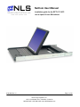
1
NetCom User Manual
Installation guide for the RFT2-17-CAT5
into a 4-post 19-inch EIA cabinet
07/01/06 Rev 1.0
Page 1 of 24
Neuro Logic Systems, Inc.
451-C Constitution Ave., Camarillo, CA 93012
805.389.5435 • 805.389.5436 • www.NLSdisplays.com
Box Inventory
As you unpack the kit, ensure that you have the following items included in the box:
1 – 1U LCD with Keyboard
1 – 2m IEC Power Cable
1 – Cable Management System (unless ordered without)
2 – Outer Rails (Mounting to Rack)
2 – Inner Rails (Already mounted to RFT)
1 – Mounting Hardware
4 – Zip Ties for securing cables to the back of the unit
If any of these parts are missing, please call your local distributor or NLS at +1 805.389.5435 x21, or email
[email protected] to receive the missing parts.
07/01/06 Rev 1.0
Page 2 of 24
07/01/06 Rev 1.0
Page 3 of 24
Introduction
Access and control multiple multi-platform computers from one Keyboard Video Mouse (KVM) console
with the NetCom system.
1. Features
•
Hot-Swap - disconnect and reconnect computers without rebooting
•
Scan-mode operation with variable time interval
•
1U Rack mountable
•
Operate the system using an On Screen Display (OSD) keyboard hotkeys
•
Create multi-level cascade arrangements. For example by cascading the NetCom with Minicom’s
Smart CAT5 KVM 16-Port model, connect up to up to 256 computers in the system
•
The computers can be placed up to 10m/33ft from the NetCom
•
Multi-platform — supports PS/2, SUN, and USB computers/servers
2. System components
The NetCom system consists of:
•
NetCom 1U 17” LCD and keyboard with a digital 16-port KVM
•
Remote Interface Connection cables (RICCs) – PS/2, SUN, USB
•
CAT5 cables (1.5m provided)
•
RS232 Serial cable
•
Rack mounts for the NetCom and the RICCs
3. Compatibility
The NetCom is compatible with:
•
PS/2, SUN and USB computers/servers
•
VGA, SVGA, or XGA monitors
•
DOS, Windows (3X, 9X, 2000, NT4, ME, XP, 2003 Server) LINUX, UNIX, QNX, SGI, FreeBSD,
BeOS, Open VMS, Novell 3.12-6, Alpha UNIX, HP UX, SUN
07/01/06 Rev 1.0
Page 4 of 24
4. Pre-installation guidelines
•
Switch off all computers
•
Place cables away from fluorescent lights, air conditioners, and machines that are likely to generate
electrical noise
•
Ensure that the maximum distance between each computer and the NetCom, does not exceed
10m/33ft
5. Connecting the NetCom system
Connect each computer to the NetCom system using the appropriate RICC and CAT5 cables. Error! Reference
source not found. illustrates the NetCom system connections with the appropriate RICC connected to a PS/2, SUN
and USB computer/server.
07/01/06 Rev 1.0
Page 5 of 24
The RICCs
The RICCs draw their power from the computer’s keyboard port (RICC PS/2, SUN) or from the USB port
(RICC USB).
Connecting a PS/2 RICC
Figure 1 illustrates the RICC.
To connect the PS/2 RICC:
1. Connect the Screen connector to the computer’s Video card.
2. Connect the Keyboard connector to the computer’s Keyboard port.
3. Connect the Mouse connector to the computer’s Mouse port.
NetServer tc2100
To computer’s
keyboard port
Keybd
Mouse
100T
To computer’s
mouse port
Parallel
Serial A
RICC
Video
Serial B
To computer’s
Video card
SCSI
CAT5 cable to Smart
CAT5 Computer port
PCI 33Mx32b
PCI 33Mx32b
PCI 33Mx32b
PCI 33Mx32b
Figure 1 PS/2 RICC
Connecting a SUN Serial RICC
Above illustrates the SUN RICC and its connections.
To connect the SUN RICC:
1. Connect the Screen connector to the computer’s Video card.
2. Connect the Keyboard connector to the computer’s Keyboard port.
Connecting a USB RICC
The RICC USB supports Windows 98 SE and later, MAC, SUN and SGI illustrates the USB RICC and its
connections.
To connect the USB RICC:
1. Connect the Screen connector to the computer’s Video card.
2. Connect the USB connector to the computer’s USB port.
07/01/06 Rev 1.0
Page 6 of 24
Connecting the CAT5 cables
1. Connect one connector to the RICCs RJ45 port.
2. Connect the other connector to one of the NetCom’s Computer ports.
3. Follow the above 2 steps for each computer.
Connecting the KVM console
To connect a KVM console to the NetCom:
1. Connect the monitor’s connector to the NetCom’s Monitor port.
2. Connect the keyboard’s connector to the NetCom’s Keyboard port.
3. Connect the mouse’s connector to the NetCom’s Mouse port.
6. Connecting the power supply
1. Connect the NetCom to the power supply using the Power cable provided. Use only power cord
supplied with the unit.
2. Switch on the computers.
7. Resetting the Switch
Resetting can be performed through the software – explained later.
8. Avoiding general rack mounting problems
Elevated operating ambient temperature
The operating ambient temperature of the rack environment may be greater than the room ambient when
installing into a closed or multi-unit rack assembly. So install the equipment in an environment
compatible with the maximum rated ambient temperature.
Reduced airflow
Install the equipment in a rack in such a way that the amount of airflow required for safe operation is not
compromised.
Mechanical loading
Mount the equipment in the rack in such a way that a hazardous condition is not achieved due to uneven
mechanical loading.
Circuit overloading
When connecting the equipment to the supply circuit, consider the effect that overloading of circuits
might have on over-current protection and supply wiring.
Reliable earthing of rack-mounted equipment should be maintained. Give attention to supply connections
other than direct connections to the branch circuit (e.g. use of power strips).
07/01/06 Rev 1.0
Page 7 of 24
9. Cascading NetCom switches
You can cascade the NetCom system. You do so by connecting the lower level NetCom Switches to
RICCs. Follow the connections as illustrated in the figure below.
With the NetCom 16 Port model, connect up to up to 256 computers through cascading.
A lower level Switch must have a different hotkey to display its OSD than a higher level switch. Changing
the OSD display hotkey is explained on page 12 below.
07/01/06 Rev 1.0
Page 8 of 24
10. Operating the NetCom system
Switch between the connected computers by either
•
Keyboard hotkeys
•
The OSD (On Screen Display) or Control software
The OSD is also the place to adjust various settings as explained below.
When switching computers the illuminated LED of the top bank indicates which computer is currently
selected.
11. The keyboard hotkeys
To switch to the next computer forwards press Shift then, +. Release Shift, before pressing +.
To switch to the next computer backwards press Shift then, -. Release Shift, before pressing -.
Note! With a US English keyboard you can use the + key of the alphanumeric section or of the numeric
keypad. With a Non-US English keyboard only use the + key of the numeric keypad.
12. Displaying the OSD
To display the OSD:
Press Shift twice. The OSD Main window appears. See Figure 2. Lines with blue text show active
computers. Lines with grey text show inactive computers.
The Type column indicates whether a computer “C” or another switch “S” is connected to the port.
Figure 2 The OSD Main window
13. Navigating the OSD
To navigate up and down use the Up and Down arrow keys.
To jump from one column to the next (when relevant) use the Tab key.
To exit the OSD or return to a previous window within the OSD press Esc.
14. Selecting a computer
To select a computer:
1. Navigate to the desired computer line.
2. Press Enter. The selected computer is accessed. An confirmation label appears showing which
computer is accessed.
Note! When the OSD is displayed you cannot select computers using the front panel Select buttons or
the keyboard hotkeys.
07/01/06 Rev 1.0
Page 9 of 24
15. The OSD settings (F2)
Press F2. The OSD Settings window appears see Figure 3.
Figure 3 The Settings window
Note! When the OSD is password protected (explained below) only the Administrator has access to the
F2 settings window.
07/01/06 Rev 1.0
Page 10 of 24
16. The General settings
With the GENERAL line highlighted, press Enter. The General settings window appears see Figure 4.
Figure 4 The General Settings window
From this window you can do the following:
Security
The OSD comes with an advanced password security system that contains 3 different security levels.
Each security level has different access rights to the system.
These levels are as follows:
Administrator (Status A)
The Administrator can:
•
Set and modify all Passwords and security profiles
•
Fully access any computer
•
Use all OSD functions
Supervisor (Status S)
The Supervisor can:
•
Fully access any computer
•
Access the following OSD functions only –F4 Scan, F5 Tune and F6 Moving the Confirmation
label.
User (Status U)
There are 6 different Users in the NetCom system. Each User has a Profile set by the Administrator that
defines the access level to different computers. There are 3 different access levels; these are explained
on page 15.
07/01/06 Rev 1.0
Page 11 of 24
Activating password protection
By default OSD access is not password protected. Only the Administrator can password-protect the OSD
or disable password protection.
To do so:
1. In the General settings window navigate to the Security line.
2. Press the Spacebar to toggle between Security On and Off. The password box appears.
3. Type the Administrator’s password (default is “admin”).
4. Press Enter. The new security status is set.
Displaying the OSD of cascaded switches
When you have cascaded NetCom switches, a lower level Switch must have a different OSD display
hotkey than a higher level switch. (See page 8.)
The hotkeys can be any of the following:
•
Shift, Shift (default)
•
Ctrl, Ctrl
•
Ctrl, F11
•
Print Screen
To change the top level hotkey:
1.
Navigate to the HOTKEY line.
2.
Choose a different hotkey than the Shift, Shift hotkey of the lower level Switches. Toggle
between the options using the Spacebar.
07/01/06 Rev 1.0
Page 12 of 24
To change a lower level hotkey:
1. Connect a keyboard and monitor to the lower level Switch and press Shift, Shift. Its OSD appears.
2. Press F2 and select GENERAL. The General settings window appears.
3. Navigate to the HOTKEY line.
4. Choose a different hotkey than the hotkey of the of the top layer switch. Toggle between the options
using the Spacebar.
Note! When a lower level Switch hotkey is changed, there is an adjustment to be made in the higher
level Switch’s OSD: This is explained on page 14-(HKEY) hotkey - Cascading.
Autoskip
When Autoskip is on, you can only access the active computers. When Autoskip is off, you can access
active and inactive computers. (This includes operating the Switch via the OSD, front panel buttons or
hotkeys).
To change the Autoskip setting:
1. Navigate to the Autoskip line.
2. Toggle between the options using the Spacebar.
Serial port
The Serial port is used for the Control Management program. Serial port On means the program can be
used.
To change the Serial port setting:
1. Navigate to the Serial port line.
2. Toggle between the options using the Spacebar.
Changing the Keyboard language
In the OSD the names of the computers can be written in 3 different languages – English (EN), German
(DE), and French (FR). The keyboard is preset to English; this can be changed as follows:
1. Navigate to the Keyboard language line.
2. Toggle between the options using the Spacebar.
Editing the Switch name
You can substitute up to 18 characters in the line. A space constitutes a character. When there is more
than one switch in the system give each Switch’s OSD a different name.
17. F7 Defaults
Press F7 to return the OSD to the factory default settings. Note! All changes made will be removed.
18. The Ports settings
From the General Settings, return to the Settings window by pressing Esc. Navigate to the Ports line and
press Enter. The Ports settings window appears see Figure 5.
07/01/06 Rev 1.0
Page 13 of 24
Figure 5 Ports Settings window
Editing the computer name
In this window you can edit the computer names with up to 15 characters. When you have a cascaded
CAT5 KVM Switch connected to a Computer port give the switch a distinct name. See Figure 5.
To erase a character:
Select it and press the Spacebar. Blank spaces remain in place of the erased character.
To erase an entire line:
Place the cursor at the beginning of the line. Keep the Spacebar depressed until the line is erased.
Keyboard (KB)
By default the Keyboard mode is set to PS, which is suitable for Windows, Linux, MAC OS, SUN Solaris
and most other operating systems.
For certain UNIX operating systems set the KB column as follows:
•
U1 for HP UX
•
U2 for Alpha UNIX, SGI, Open VMS
•
U3 for IBM AIX
(HKEY) hotkey - Cascading
When there are cascaded switches, and the lower level Switch has had its OSD display hotkey changed,
you must do the following:
Adjust the HKEY setting in the Ports Settings window of the higher level switch to reflect the lower level
switch’s new hotkey: E.g. in Figure 5 above a NetCom switch is connected to port #3 and its display
hotkey is Ctrl, F11.
To reflect the new hotkey:
Adding/changing a hotkey (HKEY)
Cascade the NetCom by connecting another NetCom Switch to a Computer port instead of a computer,
and then connecting more RICCs to the second Switch. Connect a third and fourth Switch in the same
way. With the NetCom 16 Port model, connect up to up to 256 computers through cascading.
You must define a hotkey to display the OSD of each Switch. These hotkeys must be different for the top
and bottom layers. The hotkeys can be any of the choices as set out above on page 12.
To add/change a hotkey:
1. On the line to which the Switch is connected, press Tab to jump to the HKEY column.
2. Toggle between the options using the Spacebar.
07/01/06 Rev 1.0
Page 14 of 24
3. Return to the Settings window by pressing Esc.
19. The Time settings
In the Settings window navigate to the Time line and press Enter. The Time settings window appears
see Figure 6.
Figure 6 Time settings window
Scan (SCN) - Label (LBL) - Time out (T/O)
SCN - In the SCN column, change the scan period.
LBL - In the LBL column, change the display period of the OSD label showing which computer is
currently accessed.
T/O - When password protection is activated you can automatically disable the Management keyboard,
mouse and screen after a preset time of non-use. Set this Timeout period in the T/O column.
To set the above periods:
1. On the desired line press Tab to jump to the desired column.
2. Place the cursor over one of the 3 digits and type a new number. Enter a leading zero where
necessary. For example, type 040 for 40 seconds.
Typing 999 in the LBL column displays the label continuously. Typing 000 – the label will not appear.
Typing 999 in the T/O column disables the Timeout function. Warning! Typing 000 causes the
Timeout function to work immediately. Minimum time should be not less than 005 seconds.
Typing 999 in the SCN column displays the screen for 999 seconds. Typing 000 – the computer
screen is skipped.
20. Users
In the Settings window navigate to the Users line and press Enter. The Users settings window appears
see Figure 7.
Figure 7 The Users settings window
There are 3 different access levels. These are:
07/01/06 Rev 1.0
Page 15 of 24
•
Y – Full access to a particular computer. Plus access to the F4, F5 and F6 OSD functions
•
V –Viewing access only, to a particular computer (No keyboard/mouse functionality)
•
N – No access to a particular computer – A TIMEOUT label appears if access is attempted
To give each user the desired access level:
1. Navigate to the desired computer line and User.
2. Toggle between the options using the Spacebar.
21. Security
In the Settings window navigate to the Security line and press Enter. The Security settings window
appears see Figure 8.
Figure 8 The Security settings window
The ‘T’ column on the right hand side stands for Type of password.
There can only be 1 Administrator password, 1 Supervisor password, and 6 User passwords.
To change a user name or password:
1. Navigate to the desired line and column.
2. Type a new user name / password. User authentication is done solely via the password there is no
security significance to the names.
By default the User Profile settings are full access.
22. The OSD HELP window – F1
To access the HELP window press F1. The HELP window appears see Figure 9.
Figure 9 The HELP window
Please note! All the functions set out in the Help window are performed from the Main window. The Help
window is merely a reminder of the hotkeys and their functions.
23. Scanning computers– F4
Where necessary adjust the scan time in the Time Settings window, see above.
07/01/06 Rev 1.0
Page 16 of 24
To activate scanning:
1. Press Shift twice to open the OSD.
2. Press F4. Your screen displays each active computer sequentially, with the Scan label appearing in
the top left corner.
To deactivate scanning:
Press F4.
24. Tuning – F5
You can tune the image of any remote computer screen from the Select Computer window.
To adjust the screen image:
1. Navigate to the remote computer you wish to adjust.
2. Press F5. The screen image of the selected computer appears, together with the Image Tuning label.
3. Adjust the image by using the Right and Left Arrow keys.
4. When the image is satisfactory, press Esc.
Note! Picture quality is relative to distance. The further away a remote computer is from the NetCom, the
lower the image quality, and the more tuning needed. So place the higher resolution computers closer to
the manager unit.
25. Moving the label – F6
Position the OSD label anywhere on the screen.
To position the label from the Main window:
1. Navigate to the desired computer using the Up and Down arrow keys.
2. Press F6. The selected screen image and Identification label will appear.
3. Use the arrow keys to move the label to the desired position.
4. Press Esc to save and exit.
07/01/06 Rev 1.0
Page 17 of 24
26. USB / SUN Combo keys
The connected PS/2 keyboard does not have a special SUN keypad to perform special functions in the
SUN Operating System environment. So when a RICC USB or SUN is connected to a SUN computer,
the RICC emulates these SUN keys using a set of key combinations called Combo keys. See the table
below.
07/01/06 Rev 1.0
SUN key
Combo key
Stop
Left Ctrl + Alt + F1
Props
Left Ctrl + Alt + F3
Front
Left Ctrl + Alt + F5
Open
Left Ctrl + Alt +F7
Find
Left Ctrl +Alt + F9
Again
Left Ctrl + Alt + F2
Undo
Left Ctrl + Alt + F4
Copy
Left Ctrl + Alt + F6
Paste
Left Ctrl + Alt + F8
Cut
Left Ctrl + Alt + F10
Help
Left Ctrl + Alt + F11
Compose
Application key or Left Ctrl + Alt
+ Keypad *
Crescent
Scroll Lock
Volume Up
Left Ctrl + Alt + Keypad –
Volume Down
Left Ctrl + Alt + Keypad +
Mute
Left Ctrl + Alt + F12
Sun Left key
Left Windows key
Sun Right key
Right Windows key
Alt-Graph
Right Alt or Alt Gr
Stop A
Left Ctrl + Alt +1
Page 18 of 24
27. Technical specifications
Operating systems
and Platforms
DOS, Windows, LINUX, UNIX, QNX, SGI, FreeBSD, BeOS,
Novell 3.12-6, SUN
Mouse
PS/2, Wheel mouse, Intellimouse, 5-button mouse
Resolution
1600x1200@75Hz
System cable
CAT5/ 5E/ 5+/ 6/ or 7 cables. FTP or UTP 2x4x24 AWG
solid wire
Transmission
distance
Up to 10m/33ft
NetCom Switch
System
Serial
RJ45
RJ11
Operating /
Recommended
ambient temperature
0ºC to 40ºC/32ºF to 104ºF
Storage temperature
-40ºC to 70ºC/-40ºF to 158ºF
Humidity
80% non-condensing relative humidity
RICCs
PS/2
USB
SUN
VGA
Keyboard/Mouse
System
HDD15
MiniDin6
RJ45
HDD15
USB
RJ45
HDD15
MiniDin8
RJ45
Power
From computer’s
Keyboard port
From USB port
From computer’s
Keyboard port
Connections
07/01/06 Rev 1.0
Page 19 of 24
28. Upgrading the NetCom firmware
With the NetCom Update software program you can upgrade the firmware for the:
•
OSD
•
Manager
•
RICCs
NetCom Update enables you to add new features and fix bugs in a quick and efficient manner.
You can install the NetCom Switch Update on any computer, even one not part of the NetCom system.
The NetCom Update software and latest firmware is on the NLS website. To obtain the latest firmware
for your system go to www.NLSdisplays.com/support/NetCom.
29. System requirements for the NetCom Update software
•
Pentium 166 or higher with 16 MB RAM and 10 MB free Hard Drive space.
•
Free Serial port.
•
Windows 98 and later.
30. Connecting the NetCom system
To update the firmware the NetCom system must be connected and switched on.
31. Connecting the RS232 Serial cable
To run the software, connect the RS232 Serial cable to the computer containing the software, and to the
NetCom Switch..
32. Installing the software
To install the NetCom Switch Update software, simply download the software to your computer and run
the installer.
07/01/06 Rev 1.0
Page 20 of 24
33. Starting and configuring the NetCom Update
1. Start the NetCom Update software. The NetCom Update window appears. See Figure 10.
Figure 10 The NetCom Switch Update window
07/01/06 Rev 1.0
Page 21 of 24
The table below explains the functions of the buttons and boxes in the NetCom Switch Update window.
Button or Box
Function
Selects all RICCs
Unselects selected RICCs
Starts firmware download
Displays the firmware version
number
Displays the hardware version
number
Cancels selected function
System time
Displays download status
Name of Update file
2. From the Options menu choose Com Port. The Com Port box appears.
See Figure 11.
Figure 11 The Com Option box
3. Choose an available Com Port and click OK.
Note! The RS232 Serial cable must be connected to the selected Serial port.
34. Verifying the version numbers
Before upgrading the firmware, you must first verify which firmware and hardware versions you have.
The OSD version number
To verify the OSD version number:
1.
Open the NetCom Switch Update program.
2.
In the Switch Unit box, check the OSD option. See Figure 10.
3.
Click
. The version number appears in the Switch box.
The H/W Version button is grayed out, as there is no hardware relevant to the OSD.
The NetCom Manager version number
To verify the NetCom version number:
07/01/06 Rev 1.0
Page 22 of 24
1.
Open the NetCom Switch Update program.
2.
In the Switch Unit box, check the NetCom Manager option.
3.
Click
. The firmware version number appears in the Switch Unit box.
4.
Click
. The hardware version number appears in the Switch Unit box.
Verifying the RICC version number
Before you can check a RICC, you must uncheck the Switch Unit box options.
To verify the RICC version number:
1.
Open the NetCom Switch Update program.
2.
Check one or more or all of the RICCs.
3.
Click
. The firmware version number appears after the RICC number.
4.
Click
. The hardware version number appears after the RICC number.
When “Not responding” appears, there is no computer connected, or it is switched off.
35. Obtaining new firmware
Download the latest firmware for your system from www.NLSdisplays.com/support/NetCom
36. Updating the firmware
Warning!
Never switch off any computer connected to the NetCom system during the updating process.
To update the firmware:
1.
Open the NetCom Switch Update program.
2.
In the NetCom Switch Update window, check the appropriate option in the Switch Unit box or the
desired RICC.
3.
From the File menu, choose Open. The Open box appears. See Figure 12.
4.
Navigate to the folder that contains the firmware update file. You may only see the files that match
the file selection mask.
Figure 12 The Open box
5.
Open the file.
07/01/06 Rev 1.0
Page 23 of 24
6.
Click Start. The NetCom Switch Update flashes the firmware. On completion the firmware version
number appears.
7.
Check that the updated version number is correct by pressing
.
Firmware Update generates one log file per session that displays a chronological list of actions. You can
read the log file in any ASCII text editor. The log file is located in the Windows directory.
37. Reset
Reset the software for the NetCom Manager or RICCs when for example the unit hangs or when the
mouse fails to work properly. Resetting is done via the Serial port, and avoids the need to shut down the
computer.
NOTE! The Reset function does not affect the parameters of the unit settings.
Resetting the Switch or RICC units
To reset the Switch or RICC units:
1. For the Switch, check the NetCom Switch option in the Switch Unit box.
For the RICCs, check one or more RICCs in the RICC Units box.
2. From the Options menu choose Advanced / Reset. The units reset. The system should now be
operational.
38. RICC SUN keyboard emulation
By default the RICC SUN supports US English keyboard emulation. It also supports German and Swiss
German keyboard emulation. You can download the appropriate keyboard emulation firmware from
www.NLSdisplays.com/support/NetCom Other language keyboard emulations will be posted on the
NLS Web site as they become available.
39. Troubleshooting tips
When using Firmware Update software you may sometimes get a Communication Error message.
When updating a unit and a Communication Error message appears, do the following:
1.
Check that the RS232 Serial cable’s RS232 connector is connected to the Switch’s Communication
port.
2.
Check that the RS232 Serial cable’s DB9F connector is connected to the DB9M Serial port on the
CPU’s rear panel.
3.
Restart the download process.
Electricity failure
When the electricity fails while updating the NetCom firmware, do the following:
If the electricity fails during the firmware update of the Switch, a Communication Error message
appears. Simply resume the firmware update by opening the folder that contains the firmware update file
and continue from there.
If the electricity fails during the firmware update of the RICCs a Not Responding or Upgrade Error message
appears. Restart the upgrade from the beginning.
07/01/06 Rev 1.0
Page 24 of 24