1
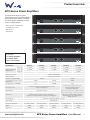
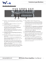
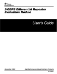
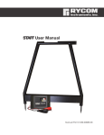
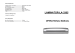
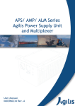
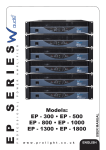
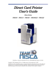
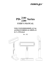
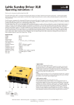
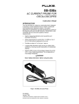
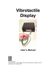
EPX Series
Power Amplifiers
User Manual
POWER
PROTECT
CLIP
I
O
CH A
CLIP
CH B
POWER
POWER
PROTECT
CLIP
I
O
CH A
CLIP
CH B
POWER
POWER
PROTECT
CLIP
I
O
CH A
CLIP
CH B
POWER
POWER
CLIP
I
O
ST
BR
PR
CLIP
PROTECT
CH A
CH B
POWER
POWER
CLIP
I
O
ST
BR
PR
CLIP
PROTECT
CH A
POWER
CH B
Order codes:
AMP24 - EPX 300
AMP25 - EPX 500
AMP26 - EPX 800
AMP27 - EPX 1200
AMP28 - EPX 2200
Safety advice
WARNING
FOR YOUR OWN SAFETY, PLEASE READ THIS USER MANUAL
CAREFULLY BEFORE YOUR INITIAL START-UP!
• Immediately upon receiving this product, carefully unpack the carton and check the contents to ensure that all the parts are present.
• Before initial start-up, please make sure that there is no damage caused during transportation.
• Should there be any damage, consult your dealer and do not use the equipment.
• Retain the carton and all packaging materials.
• In the event that the equipment must be returned to the supplier, it is important that the equipment is returned in the original carton and packaging.
• To maintain the equipment in good working condition and to ensure safe operation, it is necessary for the user to follow the safety instructions and warning notes written in this manual.
• Please note that damages caused by user modifications to this equipment are not subject to warranty.
CAUTION!
KEEP THIS EQUIPMENT
AWAY FROM MOISTURE,
RAIN AND LIQUIDS, AND
OUT OF DAMP/HUMID
ENVIRONMENTS
CAUTION!
TAKE CARE USING
THIS EQUIPMENT!
HIGH VOLTAGE-RISK
OF ELECTRIC SHOCK!!
IMPORTANT:
The manufacturer will not accept liability for any resulting damages caused by the non-observance
of this manual or any unauthorised modification to the equipment.
• Never let the power cable come into contact with other
cables. Handle the power cable and all mains voltage
connections with caution!
• Never remove warning or informative labels from the
equipment.
• Do not open or modify the equipment.
• Do not connect this equipment to a dimmer-pack.
• Do not switch the equipment on and off in short intervals,
as this will reduce the system’s life.
• Only use the equipment indoors.
• Do not expose to flammable sources, liquids or gases.
• Always disconnect the power from the mains when
equipment is not in use or before cleaning! Only handle
the power cable by the plug. Never pull out the plug by
pulling the power cable.
• Make sure that the available voltage is between 220V/240V.
• Make sure that the power cable is never crimped or damaged. Check the equipment and the power cable periodically.
• If the equipment is dropped or damaged, disconnect
the mains power supply immediately. Have a qualified
engineer inspect the equipment before operating again.
• If the equipment has been exposed to drastic temperature
fluctuation (e.g. after transportation), do not switch it on
immediately. The arising condensation might damage the
equipment. Leave the equipment switched off until it has
reached room temperature.
• If the product fails to function correctly, discontinue use
immediately. Pack securely (preferably in the original
packing material), and return to your dealer for service.
• Only use fuses of same type and rating.
• Repairs, servicing and power connection must only be
carried out by a qualified technician. THIS UNIT CONTAINS
NO USER SERVICEABLE PARTS.
• WARRANTY: One year from date of purchase.
OPERATING DETERMINATIONS
If this equipment is operated in any other way, than those described in this manual, the product may suffer damage and the warranty becomes void. Incorrect operation may lead to danger e.g: short-circuit, burns and electric shocks etc.
In case of malfunction this unit should be returned for service or inspection.
Do not endanger your own safety and the safety of others!
Incorrect installation or use can cause serious damage to people and/or property.
www.prolight.co.uk
EPX Series Power Amplifiers User Manual
2
Product overview
EPX Series Power Amplifiers
A professional range of power
amplifiers offering superior reliability
and performance, with a full range
of power options available to suit a
variety of applications.
POWER
PROTECT
CLIP
I
CH A
O
•Short circuit, overload and thermal protection
•Fan cooled
•Ground lift
CLIP
CH B
POWER
POWER
PROTECT
CLIP
I
CH A
O
CLIP
CH B
POWER
POWER
PROTECT
CLIP
I
CH A
O
CLIP
CH B
POWER
POWER
ST
CLIP
CH A
O
In the box: 1 x power amplifier,
1 x power cable
& 1 x user manual
Specifications
Output power 1kHz,
THD+N ≤0.5%
BR
PR
CLIP
PROTECT
I
CH B
POWER
POWER
ST
CLIP
BR
PR
CLIP
PROTECT
I
CH A
O
POWER
CH B
EPX 300
EPX 500
EPX 800
EPX 1200
EPX 2200
Stereo 8Ω
2 x 90W
2 x 180W
2 x 270W
2 x 400W
2 x 850W
Stereo 4Ω
2 x 150W
2 x 250W
2 x 400W
2 x 600W
2 x 1100W
Bridge 8Ω
-
-
-
1200W
2200W
Frequency response
20Hz to 20kHz±1.0dB
Input sensitivity
0.775V / 1.0V / 1.44V
S/N ratio (a-weighted, RMS)
>95dB
Crosstalk at rated power output
(8Ω at 1kHz)
>65dB
>70dB
>60
>150dB
>200
Damping factor (f=1kHz@8Ω)
Protection circuits
Thermal, short circuit, overload, DC fault protection & AC power supply fuse
Soft start, limit, thermal, short circuit, overload, DC fault protection & AC power supply fuse
Power, protect & clip
Power, protect, clip, stereo, parallel & bridge
Inputs: 2 x phono sockets, 2 x 1/4” jack sockets
Outputs: 2 x locking speaker connectors, 2 x binding posts
Inputs: 2 x XLR sockets, 2 x 1/4” jack sockets
Outputs: 2 x locking speaker connectors, 2 x binding posts, 1 x locking speaker bridge connector
LED indicators
Connectors
Cooling system
Low-noise cooling fans, variable speed fan
Power supply
Dimensions (H x W x D)
Weight
Order code
www.prolight.co.uk
>100dB
>55dB
AC240V/50Hz
87 x 481 x 297mm
87 x 481 x 297mm
87 x 481 x 297mm
87 x 481 x 450mm
87 x 481 x 450mm
9.5kg
10kg
10.5kg
18kg
21kg
AMP24
AMP25
AMP26
AMP27
AMP28
EPX Series Power Amplifiers User Manual
3
Product overview
297mm
264mm
EPX 300, EPX 500 &
EPX 800 dimensions
87mm
426mm
481mm
450mm
421mm
EPX 1200 &
EPX 2200 dimensions
87mm
426mm
481mm
www.prolight.co.uk
EPX Series Power Amplifiers User Manual
4
Technical specifications
EPX 300, EPX 500 & EPX 800 front panel
04
03
POWER
PROTECT
CLIP
I
CH A
O
05
01
CLIP
CH B
POWER
02
01 - Clip LEDs - These LEDs flash red to indicate when the
output of the amplifier has reached the maximum, and is
right on the edge of clipping. Clipping is bad for speakers
and should be avoided. It is okay if the LED blinks
occasionally. It means that the transient peaks of the
music are just hitting the full output of the amplifier.
02 - Gain control - These two knobs control the levels of
Channels 1 and 2. Usually, these controls are set all the way up. You might turn them down slightly if you have high-efficiency speakers. Also, you could use them
to control the level of line-level sources such as a CD
player connected directly to the amplifier without a pre-amplifier or mixer. After you have set the levels
02
01
for the mixer (or other signal source), adjust the level
controls on the amplifier as the final adjustment to set
the overall volume for the system. In stereo and mono mode, use both level controls to control the levels going to each speaker.
03 - Power LED - This LED illuminates when the amplifier is switched on
04 - Protect LED - If this LED is illuminated during operation,
one of the protection circuits is active. Please take the
amplifier out of operation and have it tested
05 - Power switch - Press this switch to start the operation
EPX 300, EPX 500 & EPX 800 rear panel
OUTPUTS
(4Ω min.)
MAINS
POWER AMPLIFIER
RIGHT
LEFT
Serial no.
INPUTS
CAUTION!
Remove the mains power before opening
the unit. No user serviceable parts inside,
refer to qualified service personnel.
Protect the unit against moisture and heat.
Operating temperature range 0-40°C.
This product is not intended for use
other than stated.
GROUNDLIFT
B
01
240V~50Hz
A
02
01
LIFT
T3.15 A
240V~50Hz
GND
05
03
01 - ¼” jack inputs - These inputs allow you to connect
¼”unbalanced jack plugs
02 - Phono inputs - These inputs allow you to connect
unbalanced phono plugs
03 - There are three ways of connecting your speakers: Locking speaker connectors, ¼” jack or binding posts.
The connectors are wired in parallel. (e.g. Channel 1
binding post, jack and locking speaker connectors are in
parallel and the same for channel 2).
www.prolight.co.uk
!
04
04 - Power cable socket - This is where you connect the
detachable power cable. Connect the other end to a
240V AC outlet.
05 - Ground lift switch - This switch allows the signal ground
or chassis ground to be separated in case of a ground
conflict. For the highest safety of the equipment, it is
recommended to keep the “ground lift switch” in the
GND position. In case of a ground conflict please set the
ground lift switch to GND LIFT.
EPX Series Power Amplifiers User Manual
5
Technical specifications
EPX 1200 & EPX 2200 front panel
05
06
07
POWER
ST
CLIP
I
O
08
CH A
PR
CLIP
01
CH B
POWER
02
02
03
01 - Clip LEDs - These LEDs flash red to indicate when the
output of the amplifier has reached the maximum, and is
right on the edge of clipping. Clipping is bad for speakers
and should be avoided. It is okay if the LED blinks
occasionally. It means that the transient peaks of the
music are just hitting the full output of the amplifier.
02 - Gain control - These two knobs control the levels of
Channels 1 and 2. Usually, these controls are set all the
way up. You might turn them down slightly if you have
high-efficiency speakers. Also, you could use them to
control the level of line-level sources such as a CD player
connected directly to the amplifier without a pre-amplifier or mixer. After you have set the levels
for the mixer (or other signal source), adjust the Level
controls on the amplifier as the final adjustment to set
the overall volume for the system. In stereo and mono mode, use both level controls to control the levels going to each speaker. In bridged
mode, turn the channel 2 level control down, and just
use the channel 1 control.
www.prolight.co.uk
BR
PROTECT
01
04
03 - Power LED - This LED illuminates when the amplifier is switched on
04 - Protect LED - If this LED is illuminated during operation,
one of the protection circuits is active. Please take the
amplifier out of operation and have it tested
05 - Stereo LED - This illuminates in stereo mode
06 - Bridged LED - This illuminates in bridged mode
07 - Parallel LED - This LED illuminates in parallel mode
08 - Power switch - Press this switch to start the operation
EPX Series Power Amplifiers User Manual
6
Technical specifications
EPX 1200 & EPX 2200 rear panel
09
02
01
08
06
05
BR
LIMITER
HIGH BYPASS LOW
ON
INPUT
CH-B
MAINS
OFF
07
PR
01
02
LIFT
GND
LINK
CH-A
OUTPUTS CH-B
09
CAUTION!
ST
GROUNDLIFT
LINK
CH-B
CIRCUIT BREAKER
08
INPUT
CH-A
OUTPUTS CH-A
POWER AMPLIFIER
240V~50Hz
HIGH BYPASS LOW
OUTPUT
BRIDGE
PINOUT
CH-A
1+
1-
2+
2-
POS
NEG
CH-B
1+
240V~50Hz
1-
2+
2-
POS
NEG
BRIDGE
Serial no.
04
10
1+
1-
2+
2-
POS
NEG
03
01 - XLR inputs - These inputs allow you to connect balanced
XLR plugs. These are wired with pin 2 hot, pin 3 cold and
pin 1 ground
02 - ¼” jack inputs - These inputs allow you to connect ¼”
unbalanced jack plugs
03 - There are two ways of connecting your speakers: Locking speaker connectors or binding posts. The connectors are wired in parallel. (e.g. Channel 1
binding post and locking speaker connectors are in
parallel and the same for channel 2).
When the amplifier is used in bridged mono mode use
either the output bridged locking speaker connectors or
the two red binding posts.
04 - Locking power socket - This is where you connect the
detachable locking power cable. Connect the other end
to a 240V AC outlet.
05 - Amp mode - This switch determines the input signal
routing within the amplifier. For most applications stereo
will be used. Stereo: This is the normal mode for amplifying stereo
signals. It accepts left and right inputs and routes them
to the left and right outputs.
Parallel: This mode is used when you want to send
mono signals to both outputs. It accepts a single input
into channel 1 and routes it to both the channel 1 and
channel 2 outputs. Each channels level control adjusts
the gain for each channel.
Bridge: This mode accepts a single input into channel 1
and uses both amplifier outputs to double the power to
one speaker output. Use channel 1 level control to adjust
the gain. Turn channel 2 level control to minimum.
www.prolight.co.uk
!
Remove the mains power
before opening the unit.
No user serviceable parts
inside, refer to qualified
service personnel.
Protect the unit against
moisture and heat.
Operating temperature
range 0-40°C. This
product is not
intended for use
other than stated.
06 - When engaged the limiter switch protects your speakers from the effects of clipping. It is designed to
be virtually transparent and you should hear very little
audible difference. It is recommended that you always
have this switch active unless you are using external
compressor/limiters.
07 - Ground lift switch - This switch allows the signal ground
or chassis ground to be separated in case of a ground
conflict. For the highest safety of the equipment, it is
recommended to keep the “ground lift switch” in the
GND position. In case of a ground conflict please set the ground lift switch to GND LIFT.
08 - These balanced XLR outputs can be used to loop
through the signal to additional power amplifiers.
09 - Crossover: For normal operation set the mode switch to
Bypass. Low/High Pass Mode: When using the “Low/
High Pass Mode”, the amplifier can be configured for
High Pass or Low Pass operation.
10 - Circuit breaker - If the amplifier is over driven or a
serious problem occurs the resettable circuit breaker
may be activated. Push to reset the circuit breaker
when necessary to restore power to the amplifier. If the
breaker will not reset, contact your nearest authorised
repair centre for assistance.
EPX Series Power Amplifiers User Manual
7
Operating instructions
Rack installation
The EP Series is built for 19” racks. The rack you use should be a ‘double door rack’ where you can open
the front and rear panel. When mounting the amplifier into the rack, please make sure that there is
enough space around the amplifier.
Be careful when mounting the amplifier into the rack. Put the heaviest products into the lower part of the rack. Be aware that fastening the amplifier with four screws on the front panel is not enough.
If the racks are being transported or used for mobile use, additionally fasten the products by
connecting the rear brackets with the side or ground bars of the rack. In this way, the amplifier
cannot be pushed backwards. The front panel is not designed to absorb acceleration forces
occuring during transportation.
Inputs
Short cables runs improve the sound quality remarkably. Input cables should be short and direct,
since high frequencies will mostly be absorbed if the cables are unnecessarily long. Besides that a
longer cable may lead to humming and noise problems. If the cable runs are unavoidable, you should
use balanced cables.
Outputs
The high damping factor of your amplifier supplies a clear sound reproduction.
Unnecessarily long and thin cables will influence the damping factor and thus the low frequencies in a negative way. In order to safeguard good sound quality, the damping factor should lie around 50.
The longer a cable has to be the thicker it should be.
Connect your speaker systems via the locking speaker connectors or the Bannana/Screw combination
(red+, black-)
Connection to the mains
Connect the amplifier only after having made sure that the correct voltage (240V) is supplied and that
the ground cable is earthed. This product falls under Class 1. Do not detach the ground cable.
www.prolight.co.uk
EPX Series Power Amplifiers User Manual
8
Operating instructions
Operation
After having connected your amplifier to the mains, turn both gain controls counter clockwise to the
“min” position. The last product to be switched on is amplifier. The “ON” and “PROTECT” LED lights up
now. If it does not, check if the amplifier is connected to the mains correctly.
After the turn on delay the speakers are activated (PROTECT-LED is off).
After having set the volume controls of the pre-amplifier to the “OFF” position, turn the gain controls of
your amplifier to mid-position. Now adjust the volume with the gain controls CH A and CH B.
All important operating modes of the amplifier are arranged on the front panel.
-20 dB to 30dB - Output level
Clip - Short circuit or impedance too low or signal distorted
Protect - Active during stabilisation period after switching on or when one of the protective circuits is activated
If you want to switch off the system, switch off the amplifier first in order to avoid acoustic shocks on the speakers.
Problem Chart
Problem
Cause
Solution
No power
The power cable is not connected
Check the power cable and any extension cables
No sound
The power cable of the respective product is
not connected correctly or not at all.
Check the power cable and if the plugs are properly
connected with the sockets
The connection socket or the plug is dirty
Clean the socket and/or the plug
Noise
The input signal is too strong
Reduce the input signal via the gain control
Fan does not work,
LEDs do not light up
The power cable is not connected
Connect the power cable
DC voltage on input
Switch amplifier off and have the product checked
by a service technician
Amplifier overheats due to obstruction
Clean the fan grill
Impedance of speakers too low
Ensure minimum 4Ω load
Short circuit in speaker connection or in speakers
Check speakers and connections
Protect LED lights
up permanently
www.prolight.co.uk
EPX Series Power Amplifiers User Manual
9
Operating instructions
CAUTION! - DANGER TO LIFE
DISCONNECT FROM THE MAINS BEFORE
STARTING MAINTENANCE OPERATION
Cleaning and Maintenance
We recommend a frequent cleaning of the product. Please use a soft lint free and moistened cloth.
Never use alcohol or solvents.
There are no serviceable parts inside the product except for the fuse. Maintenance and service
operations are only to be carried out by authorised dealers.
Replacing the fuse
Only replace the fuse with a fuse of the same type and rating.
Before replacing the fuse, unplug the mains cable.
Procedure:
Step 1: Open fuse holder on the rear panel with a screwdriver.
Step 2: Remove the old fuse from the fuse holder.
Step 3: Install the new fuse in the fuse holder.
Step 4: Replace the fuse holder in the housing.
Should you need any spare parts, please use genuine parts.
Should you have any further questions, please contact your dealer.
www.prolight.co.uk
EPX Series Power Amplifiers User Manual
10
WEEE notice
Correct Disposal of this Product
(Waste Electrical & Electronic Equipment)
(Applicable in the European Union and other European countries
with separate collection systems)
This marking shown on the product or its literature, indicates that it should not be disposed of
with other household wastes at the end of its working life. To prevent possible harm to the environment or human health from uncontrolled waste disposal, please separate this from other
types of wastes and recycle it responsibly to promote the sustainable reuse of material resources.
Household users should contact either the retailer where they purchased this product, or their
local government office, for details of where and how they can take this item for environmentally
safe recycling.
Business users should contact their supplier and check the terms and conditions of the purchase contract. This product should not be mixed with other commercial wastes for disposal.
www.prolight.co.uk
EPX Series Power Amplifiers User Manual
11
www.prolight.co.uk
EPX Series Power Amplifiers User Manual
12