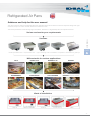
1
User Manual Refrigerated Air Pans self contained or remote refrigerated 36 Refrigerated Air Pans Guidance and help for this user manual This user manual is valid for all refrigerated Air Pans, regardless of the various kinds of versions respective design and hight of the well, drop-in or slide-in version, Gastronorm or Euronorm size. The shown possibilities shows the big range of variations, but there is a big felxibility with our bespoke solutions. Various versions for your requirements USER MANUAL Versions UKW ref. well variable presentation area BAKERY flat presentation area BAKERY H FOODSTATION COLD DRAWER high air discharge outlet Presentation + Preparation Presentation for glass tops PART A Different units for various applications UKW BAKERY H 32 BAKERY H 38 BAKERY DIFFERENZIAL FOODSTATION COLD DRAWER BAKERY - Bespoke solution Kinds of installation Drop-in Built-in underneath Slide-in Placed on top PRO 37 USER MANUAL Operating- and Installation instruction PART A Copyright © October 2011, AKE Ausseer Kälte- und Edelstahltechnik GmbH All rights reserved. No part of this publication may be reproduced, stored in a retrieval system, or transmitted in any form or by any means, electronic, mechanical, photocopying, recording or otherwise, without the prior written permission of AKE. Document: Revision: Valid from: User Manual - refrigerated Air Pans.indd 11A October 2011 AKE reserves the right to change specifications and construction, as part of ongoing product improvement. 38 Contents 1 Page Introduction Welcome Warranty and liabilities Symbols and notes Fundamental safty notes Ongoing development Validity 40 40 41 41 41 42 2 Purpuse of use 43 3 Proper use of the unit 43 4 Improper use of the unit 43 5 Safety notes 43 Fundamental operating notes Start-up Switching on the appliance Setting the temperature Automatic defrosting Manual defrosting Lighting (external) 44 44 44 44 45 45 45 7 Loading restriction 45 8 Operating description 47 Cleaning and care General recommendations Detergents Special cleaning hints 48 48 48 49 10 Trouble shooting 51 11 Dangers 11.1 Electrical energy 11.2 Risk of injury 53 53 53 6 9 1.1 1.2 1.3 1.4 1.5 1.6 6.1 6.2 6.3 6.4 6.5 6.6 9.1 9.2 9.3 USER MANUAL PART A USER MANUAL PART A PART B TECHNICAL INFORMATION Installation and start-up instructions - help and advice Installation and start-up instructions - for authorized installers Maintenance and servicing Spare parts Programmable digital refrigeration controller Schematic circuit diagram Declaration of conformity Personal notices 54 55 61 61 63 66 67 68 39 Refrigerated Air Pans 1. Introduction 1.1. Welcome With the purchase of this new refrigerating equipment you have decided on a product that combines the highest technical demands with practical service comfort. USER MANUAL We recommend that you read these operating and maintenance instructions carefully in order to become familiar with the product quickly. PART A • Before you start the refrigerated air pan, please read the regards and instructions in this manual. • Take your time to read the user manual, it is worth your investment. The indicated instructions here, general and technical, will help you to keep your device in an optimal operating condition for a long time. • Unfortunately a manual can not consider all eventualities. Do not hesitate in case of ambiguity by the installation, during the operating or by the attendance, to coll your dealer. Often some questions can be cleared by a simple telephone call. With the proper treatment you will enjoy this appliance for a long time. Please keep these operating and maintenance instructions to consult in case any maintenance and repairs are needed. 1.2. Warranty and liabilities Fundamentally, our „General terms of sale and delivery“ are valid. These are known to the operator upon the signing of the contract at the latest. Claims of warranty and liability for damage to persons and property are not possible, if they result from one or several of the following causes: • Improper use of the unit. • Improper assembly, start up, operation & maintenance of the unit. • Operating the unit with defective safety devices or safety devices which have not been installed properly and are not in working condition. • Disregard of the instructions in the operating manual concerning transportation, storage and installation. • Unauthorized mechanical or electrical changes to the unit. • Insufficient maintenance of wear and tear parts. • Unauthorized repair. • Extreme environmental exposure, fire, explosions e.g. • Forces of nature or force majeure risk Also excluded from the liabilities are. • Breakage of glass, breakage of plastic components, cartrige seal or illuminating parts. • All damages, which could be arise by wrong setting the control unit, from unqualified people. • Damage or malfunctions based on a wrong assembling of the cooling unit after the cleaning of the unit. WARRANTY CLAIMS CAN ONLY BE FORWARDED IF ALL INSTRUCTIONS ARE STRICTLY FOLLOWED! 40 1.3. Symbols and notes This symbol points to important references for the proper use of the unit. Not paying attention to these references can lead to a working disruption of the unit or to the environment! Ignoring these references may result in dire consequences for your health and/or can lead to property damages! This symbol means: Hot surface, do not touch the surface“ - Attention, risk of burning! The top of the shelves, the glass and s/s columns at the back of the unit may be hot This symbol points to operation tips and especially useful information of optimal use. Helps you to use all functions on your unit optimally. USER MANUAL This danger symbol means a potential or direct threat to the life and health of persons and/or a possible dangerous situation. PART A 1.4. Fundamental safety notes THE CONNECTIONS AND ANY TECHNICAL ADAPTATIONS ON THE REFRIGERATED EQUIPMENT ARE ONLY TO BE CARRIED OUT BY SPECIALISTS! THIS IS ESPECIALLY VALID FOR ANY WORK ON THE COOLING TECHNOLOGY, ELECTRICAL INSTALLATION, WATER CONNECTION AND MECHANICAL WORK. ANY ADAPTATION IS TO BE AUTHORIZED BY THE MANUFACTURER! • Those covers bearing a warning may only be opened by specialists! • The bottom and back panels are not to be cleaned by water jet. • Protective covers and devices may not be removed due to risk of injury! • The control system may only be opened by an expert. • Air currents near the refrigerating unit resulting from improperly installed ventilation or draughts are to be avoided, in order to ensure the efficient functioning of the refrigerating unit. • The surrounding temperature may not exceed 25°C; the relative humidity may not exceed 60% over a long period of time. • All displayed goods must have a core temperature from +5° or below when they are loaded into the cabinet • Due to risk of injury, sharp objects are not to be stored loosely in the refrigerating unit. • Any glass parts are to be treated with the necessary care in order to avoid injuries resulting from broken glass. • Components and operating equipment may only be replaced by original parts. 1.5. Ongoing development AKE reserves the right to change specifications and construction, as part of ongoing product improvement. 41 Refrigerated Air Pans 1.6. Validity These operating instructions are valid for the models: USER MANUAL Refrigerated well UKW GN, EURO, XL self contained or remote refrigerated PART A Refrigerated well BAKERY flat, deep, combined or slanted 8° self contained or remote refrigerated Refrigerated well Bakery H self contained or remote refrigerated Refrigerated well Praline H self contained or remote refrigerated Refrigerated well DIFFERENZIAL M1 self contained or remote refrigerated Refrigerated well FOODSTATION self contained or remote refrigerated Refrigerated well KÜHLLADE self contained or remote refrigerated 42 2. Purpose of use These refrigerated air pans can be installed in virtually any counter and can be provided as fully self contained – just plug it in and turn on – or remote, where there is a need to locate the compressor at a different location They are suitable for the refrigeration and presentation of foodstuffs and drinks at temperatures adjustable in range from +4°C to +12°C. This refrigerated equipment is not suitable for chilling foods. Any products to be presented have to be pre-chilled to the temperature required before being placed in the unit. DO NOT FILL WITH HOT FOODS AND DO NOT OVERFILL! 3. Proper use of the unit USER MANUAL Before loading the air pans with food or beverages, please wait until the desired temperature has been reached. PART A The drop-in refrigerated air pans conform to current state-of-the-art technology. They are constructed in accordance with the recognized safety regulations and are reliable. However, health and/or life threatening circumstances could arise for the user or a third party or damage could be done to the appliance or other property or equipment should the unit be operated by non-trained personnel in a manner that is improper or in disregard of the regulations. The appliance may only be operated in a technically acceptable condition and in accordance with all regulations, safety regulations and with conscious regard of the operating instructions! Any other uses beyond those intended are to be considered as not being in compliance with the regulations. The manufacturer/supplier is not liable for any damages resulting from such actions. The user bears the entire risk. Use in accordance with the regulations includes observance of the mounting and operating instructions and keeping up with the inspection and maintenance regulations. After cleaning the appliance is to be checked for any loose connections, shears and damages. Any defects found should be repaired. The appliance is not to be used for non-operating purposes. Any changes to the appliance are to be made solely by the manufacturer! When replenishing the refrigerant only use the refrigerant indicated on the label. Refilling is only to be carried out by authorized service personnel. 4. Improper use of the unit The refrigerated air panss are not suitable for chilling foods. No foodstuffs having a higher temperature than indicated are to be filled into the tubs. Safe operation at temperatures of less than +2°C is not possible. The ventilation ducts in the front and back plenum of the presentation area may not be covered as doing so will cut off the air circulation and result in prevention of the cooling function. 5. Safety notes All safety regulations were followed during manufacturing, particularly the VDE regulations (Association for Electrical, Electronic & Information Technologies) and international CEE regulations. The appliance was subject to a comprehensive final check at the plant. 43 Refrigerated Air Pans 6. Fundamental operating notes 6.1. Start up After placement or moving the refrigerated air pans, wait at least two hours before starting. This rest period is needed for the oil to run back into the compressor in case it could have shifted during transport (only valid for slef contained units). USER MANUAL We recommend cleaning the equipment with a suitable disinfectant before first start up. PART A The equipment must have reached the product manufactures indicated temperature before first filling. It is recommended to switch the new equipment on for a period of 24 hours before first filling. 6.2. Switch on the appliance The refrigerating unit is switched on and off by pressing the STANDBY button (5) for approx. 4 seconds. Above the buttons there is a digital display of the cooling regulator. This field shows the average temperature and any errors. Before filling the air pans with food, please wait until the desired temperature has been reached Button 1 UP - Button Defrosting can be started any time by pressing the UP-button for 3 seconds Button 2 DOWN - Button The DOWN button can clear an alarm Button 3 LIGHTING - Button Button for external lighting (if available) Button 4 SET - Button While SET button is pressed, the setpoint is indicated Button 5 STANDBY - Button With this button the controller is switched to standby mode. Pressing the button a second time, restarts the unit. 6.3. Setting the temperature The interior temperature is regulated by an programmable digital refrigeration controller. This is located underneath the refrigerated well and is easily accessible on operators side. The air pans are set to maintain +5°C as per factory setting. Your desired temperature can be set by holding down the SET button (4) and simultaneously pressing UP - button (1) for higher temperatures or DOWN - button (2) for lower temperatures. THE DESIRED VALUE CAN ONLY BE SET WITHIN A CERTAIN RANGE IN ORDER TO PREVENT ANY OPERATING ERRORS. 44 After resetting the temperature some time needs to pass before the desired temperature has been achieved. Please check the interior temperature a few hours afterwards with an exact thermometer and reset the thermostat if needed. Depending on the surrounding temperature and humidity, the interior temperature is not to be set too low as this could lead to icing on exposed areas of the cooling element. This will interfere with the cooling performance and with the continuous defrosting which has been set by your specialized dealer for a certain interval. 6.4. Automatic defrosting 6.5. Manual defrosting Defrosting can be started any time by pressing the UP - button (1) for 3 seconds. During the process of defrosting the respective LED is illuminated. The LED flashes if defrosting is requested, but may not be started yet due to interlock conditions. USER MANUAL Automatic defrosting takes place via the electronic thermostat and is fully automatically controlled. The defrosting process takes maximum 30 minutes. Defrost cycles are pre-programmed and starts every 3 hours (self serve displays) or 2 hours (displays for assited service). Cooling mode starts automatically after the end of defrost mode. PART 6.6. Lighting External lighting (e.g. for sneeze guards) can be connected to the control unit and is then switched ON / OFF by pressing the LIGHT button (3) on the controller display. A 7. Loading restriction The refrigerated air pans, model UKW, are equipped with base decks, which are adjustable in height and angle. Additionally you can use different Gastronorm containers. Therefore choices of divisional bars are available. Full-size Gastronorm containers GN 1/1 can be placed directly on the adjustable brackets, smaller containers require additional divisional bars - different possibilities see figure on page 47. The maximum height of the usable GN containers is up to 150 mm. This offers you a wide range of ways to display your merchandise. Beverages, base decks and Gastronorm containers can be places side by side in one refrigerated unit at same time. LOADING HEIGHT: The lower edge of the air ducts is the maximum borderline for filling! FUNCTIONALITY CAN ONLY BE GUARANTEED IF THE DISCHARGE AND RETURN AIR VENTS ARE KEPT CLEAR AND THE CHILLED AIR CURTAIN IS NOT IMPAIRED. UKW models are designed for refrigeration and presentation of goods inside the well, the models BAKERY and BAKERY H are designed to present goods on flat base decks - flush with the counter top. 45 Refrigerated Air Pans BAKERY for flat presentation, flush mounted on same level like the counter top. Can be equipped with material of the counter top (stone or Corian) USER MANUAL Suitable for low goods Loading height: 50mm BAKERY H offers same features like BAKERY; with raised air tower it is suitable for presenting larger products. PART A Loading height: BAKERY H-32: 110mm BAKERY H-38: 170mm BAKERY DIFF: 145mm FOODSTATION: 110mm Models BAKERY Kombi and BAKERY FOODSTATION offering flat presentation decks combined with storage area for Gastro norm containers - presentation and preparation on small surface. BAKERY Kombi FOODSTATION FS PROPER FUNCTION OF BAKERY, BAKERY H AND FOODSTATION IS ONLY POSSIBLE IN COMBINATION WITH A SURROUNDING GLASS, CLOSED ON 3 SIDES. SERVICE SIDE CAN BE OPERATED OPEN! 46 8. Operating description The goods being presented are cooled in drop-in wells with ventilation by means of a directed cold air haze. USER MANUAL This air haze is moved by means of ventilators which suck the air from the goods area through a return air duct (1). The air then enters the evaporator below the goods display panel (2), circulating evenly. At the same time the air is chilled and blown into the goods area through discharge air vents (3). The airflow takes place via an angled ventilation plate (4). By exactly determining the components very even air distribution is obtained. PART A LOADING It is important to leave adequate free space for the refrigerated air to circulate over the goods. Product should be kept clear of the shaded areas, shown in the picture. The air louvers at the front and rear of the cabinet must not be covered at all. Place the adjustable base decks in correct height, so that the refrigerated air curtain is never blocked by goods. 47 Refrigerated Air Pans 9. Cleaning and care The following is advice on maintenance, care, trouble shooting and service for your refrigerated air pans. The interior and the outside of the unit have to be cleaned every day in accordance with hygiene regulations. Only then can you guarantee optimal presentation of the goods. CAUTION : USER MANUAL BEFORE YOU START TO CLEAN AND CARE SWITCH OFF THE APPLIANCE AND DISCONNECT IT FROM THE MAINS! PART A For cleaning purposes the unit must be turned off. Therefore, the best time for cleaning is at the end of your working day. The air pan can be switched off during the night or outside of opening hours. 9.1. General recommendations • • • • The unit has to be cleaned daily. Wear acid-proof gloves while cleaning the parts to prevent skin irritations. After cleaning with special cleaners you have to wash all parts with clear water and dry them so that there is no cleaner residue on these parts. It is absolutely necessary to bear some fundamental things in mind to keep this stainless steel unit working and to maintain its long life: - always keep the stainless steel surface clean. - make certain there is always enough fresh air on the surface. - never let the surface come into contact with rusty material. 9.2. Detergents USE THE FOLLOWING DETERGENTS ! • • • • • Lukewarm soapy water Use lukewarm soapy water for all surfaces that are in direct contact with the goods. Glass-cleaner Removes grease from glass-surfaces. You can lift the glass panels for easy cleaning of the glass and the surfaces underneath. Stainless-steel-cleaner The stainless steel surfaces should be cleaned with a stainless-steel-cleaner only. Lamps The lamps are to be cleaned with soft paper or cloth only. Drawers, GN pans Easily removable without tools for separate cleaning. Use brushes with plastic or natural bristles for cleaning. AVOID THE FOLLOWING DETERGENTS ! • • • • 48 Do not use acid, bleaching or chlorine cleaners. Never use high-pressure, water pressure or steam jet cleaning machines. Do not use inflammable detergents. Never use sharp-edged or metallic tools like steel-wool or scrubbing cleanser for cleaning. 9.3. Special cleaning hints Cleaning ot the interior and the evaporator • Take out the GN containers or base decks (1) and air plenums (2) and inner tray from the well. First of all remove visible dirt inside the well (bottom) to avoid a blockage of the drain (5 und 6). Open the cover from the evaporator unit (3). Entire s/s housing and evaporator coil can be rinsed safety and easily with a hand spray (4). Fans in low voltage (24V) allow dangerfree cleaning. Lift up the evaporator unit and move the lock to the left (5 und 6) – now the evaporator is fixed and allows easy access for cleaning corners and floor of the well (7). Picture 2 Picture 3 USER MANUAL Picture 1 PART A Picture 4 Picture 5 Picture 6 Picture 7 • ATTENTION: Before cleaning the unit with water please check that the water can run off. If the unit isn’t plumped to a floor drain, place an external bin below the drain to collect the wastewater. • The evaporator and the interior have to be cleaned with lukewarm soap water. Always dry the interior after cleaning. After cleaning lift the evaporator, remove the lock and drop the evaporator back in its original position. • Insert the inner tray, position the air plenums with the hanging tracks and drop in the base decks or GN containers. • Never clean the outside of the refrigerated well with a water hose or an abrasive sponge. Avoid flowing water near these areas. • All other surfaces can be cleaned with soft detergents or water. Each self-contained refrigeration unit requires periodic cleaning of the condenser unit. The condenser coil (looks like a radiator and is directly in front of the fan, on operators side) requires periodic cleaning. A dirty condenser is the main cause of refrigeration overheating, burnout and poor cooling levels. Similar to the daily merchandise area cleaning, it is necessary to remove the static dust build up from the condenser coils to ensure effective and trouble free operation. 49 Refrigerated Air Pans Condenser cleaning instructions • • • • Remove air grill / louver in front of the condenser coil. Remove the dust from the condenser coil; this can be done with either a brush or a vacuum. Be careful and don‘t bend the lamellas. Replace the air grill panel USER MANUAL Please assure that the air-in and air-out openings (grille) for ventilation are never blocked! PART A ATTENTION ! THE LAMELLAS OF THE CONDENSER COIL ARE VERY THIN AND SHARP! AVOID DIRECT CONTACT TO PREVENT INJURIES! CAUTION : AFTER ALL CLEANING HAS BEEN COMPLETED THE DISPLAY CASE HAS TO BE RETURNED TO ITS ORIGINAL STATE IN ORDER TO GUARANTEE EFFICIENT OPERATION! In addition to daily cleaning, service and maintenance of the display case is required to be carried out in regular intervals by qualified specialists. ( See Chapter: Part B - SERVICE NOTES on page 66 ) 50 10. Trouble shooting FAULT The cabinet does not operate The evaporator iced up POSSIBLE CAUSE REMEDY There is no power supply to the unit Check if plug is firmly in the socket No power at receptacle Check fuse / circuit breaker of the building; Restore power to the cabinet Wrong setting of the programmable controller, or digital display don‘t work Call authorized service personnel Ventilation louvers/ducts are blocked Remove blockage, air vents must be kept free Too warm or too much food Add only pre-chilled food and do not overload the unit Set point too high Set to desired temperature Ambient temperature above 25°C Adjust store air conditioning, avoid heat sources nearby the cold unit and direct sunlight Too much air movement inside the room The unit should not be placed on places with strong air circulation Condenser coil blocked or dirty Remove dust and debris Evaporator coil iced up De-ice coil (manual defrosting or power off) Failure malfunction of the condenser unit or other cooling components Call authorized service personnel Refrigerant level low Call authorized service personnel Defrosting does not start Defrost cycle is not suitable Start manual defrosting Call authorized service personnel Inadequate ventilation inside the cabinet Leave adequate free space for the refrigerated air to circulate within the cabinet Ambient temperature above 25°C and relative humidity above 55% Adjust store air conditioning to maintain required ambient conditions inside the room Fans not operating Call authorized service personnel USER MANUAL It sometimes can have simple causes, if the unit is working incorrectly or it does not work for a longer time. This could be removed independently. Before requesting service, please check the following: PART A 51 Refrigerated Air Pans Status display and error notification: USER MANUAL MESSAGE PART A CAUSE ERROR ELIMINATION Refrigerating chamber temperature above alarm limits (parameter A1) Refrigerating chamber temperature below alarm limits (parameter A2) Sensor F1 error, short-circuit Control sensor F1 Sensor F1 error, break Control sensor F1 Sensor F2 error, short-circuit Control sensor F2 Sensor F2 error, break Control sensor F2 Intern error of the control unit Send the controller for repair Memory error Check all parameters Data loss at parameter memory Send the controller for repair Should the options listed not be the cause of the error, please contact customer service. THE MANUFACTURER IS NOT LIABLE FOR LOSS OF GOODS, EVEN IF THE APPLIANCE IS STILL COVERED BY WARRANTY. IT IS RECOMMENDED THAT THE TEMPERATURE OF THE APPLIANCE BE CHECKED PERIODICALLY. 52 11. Dangers 11.1. Electrical energy Switch off the appliance immediately when there are interruptions in the electrical power supply! Any work carried out on the electrical units or utilities may only be carried out in accordance with electrical regulations by an electrician specialist or by those being instructed and supervised by an electrician specialist. DO NOT SPLASH OR POUR WATER ONTO CONTROL PANEL OR WIRING.. Appliances and unit components which are subject to inspection, maintenance and repair work have to be completely disconnected and volt-free. First, check whether the activated parts have indeed been disconnected and are volt-free, then ground and short them out. Insulate any adjacent parts that are also energized! CAUTION: RISK OF INJURY ! USER MANUAL CAUTION: ELECTRIC SHOCK HAZARD ! PART A BE SURE THAT THE UNIT IS DISCONNETCTED AND VOLT-FREE BEFORE STARTING ANY INSPECTION, MAINTENANCE OR REPAIR WORK. 11.2. Risk of injury Some cooling appliances are equipped with gas springs, which keep the evaporator in the upright position during cleaning and service. Once the gas springs begin to weaken and are not able to keep the evaporator in the upright position anymore, they are to be removed and replaced immediately by a specialized service representative. Take care while cleaning the condenser coil, there is danger to cut on the sharp lamellas. CAUTION: THE LAMELLAS OF THE CONDENSER COIL ARE VERY THIN AND SHARP! AVOID DIRECT CONTACT TO PREVENT INJURIES! 53 Refrigerated Air Pans Installation and Start-up instructions - Help and Advice Control unit Easy to install Surrounding mounting flange; drop-in from above into the cut out counter top Display detachable for installation in cladding Water resistant display! Continuous regulation of air flow via fan speed TECHNICAL INFORMATION Digital display fixed in cladding Install heavy cabinets by using optional base unit to slide-into the counter Evaporation Evaporation for self contained and remote refrigerated ref. wells: Manual evaporation tray 1) Connect to floor drain 2) Drain tray, to empty manually (optional extras) 3) Electrical evaporation tray (optional extras) Feet adjustable in height PART B Air circulation Optimum air circulation for condensing unit: Provide front and rear openings twice the surface area of the condenser for adequate air circulation Standard: Air in on service side and air discharge on customer side Protection of condenser Optional extra: Air filter protects the coil againts dust, greasy air, damage and injuries Easy cleaning in a dish washer Removable filter for condenser On demand: Ventilation on service side Easy to clean Air inlet and outlet on service side is only possible with our optional available base unit! Choose the configuration that suits your servery layout best - before your order! 54 Lift up evaporator allows easy access for cleaning and service, tiltable front and cover glasses for cleaning Rinse off with hand spray Easy access for cleaning Installation and Start-up instructions for authorized refrigeration companies and qualified service personnel First steps Control of delivery Checking for transport damage at the time of delivery is recommended. Any damages are to be recorded and confirmed in writing at the time of delivery and signified from the carrier. For any damages arising after unpacking, you are obliged to immediately communicate this in a written report and a telephone call to the supplier. Installation Don’t tilt the refrigerated unit during the installation, the compressor unit could be damaged (only self contained units). Completely remove the plastic film before start up. Take care that your counter frame will carry the weight of the display case and fix the unit. It is essential that the countertop is perfectly level before the unit is mounted. The openings for air ventilation (air-in and air-discharge) are recommended the double size of the condenser surface! Please avoid placing the unit near any equipment which produce a lot of steam (i.e. dishwasher, etc.), as this will cause icing of the evaporator – this will reduce performance of the unit. The air pans are designed to operate under normal ambient conditions of 25°C with up to 55% relative humidity. Ideally the cases should be located so as to avoid excessive air movement from doors, air-conditioned vents, and other air sources or excessive heat from windows, sun, flood lamps and other heat sources. TECHNICAL INFORMATION Transport is covered under your responsibilities. Failing to report any transport damages with the currier within the set time leads to the loss of responsibilities by the carrier. PART B CORRECT INSTALLATION IS NECESSARY FOR A TROUBLE-FREE START UP OF THE REFRIGERATED UNIT. EVERY INSTALLATION MUST CONFORM TO THE LOCAL ELECTRIC, SAFETY, AND HYGIENE REGULATIONS. Preparation The air pans are easy to install with a minimum of tools. All counter work needs to meet the technical specification in terms of weight, cut out and support. All drop-in units require installation level with the counter and we recommend to protect the counter surface at the time of installation to prevent for possible damages. At the time of installation please remove all internal base trays as well as glass shelves to prevent damage and to gain access to the cooling well. Please ensure the counter and the countertop are perfectly level before installing the cabinet. The drain should be at the lowest point of the well. Please test that the water can drain freely. If not expressed in the description, all refrigerated units should have a connection to an external drain or at least a manual condensate tray (optional) or an electrical condensate evaporation pan (optional). Each electrical installation work is only to be carried out by nominated specialists. Ensure that needed tools and technical staff is available for the installation. Power supply The units may only be connected to a power socket with a nominal voltage 230 V / single phase / 50 cycles. Electrical Isolation If a plug and socket is used to connect the cabinet, it must be accessible after the cabinet is installed in its final position. If the cabinet is hard-wired to the mains supply, without using a plug and socket, a means of isolation must be provided. 55 Refrigerated Air Pans Installation and Start-up instructions for authorized refrigeration companies and qualified service personnel Installation of the controller display With self contained air pans the control unit is mounted underneath the ref. well, alongside the compressor housing. With remote refrigerated air pans the control unit will be loosely attached.. Each control unit consists of a control panel / display and the PCB power box. Both are built in a stainless steel box. TECHNICAL INFORMATION The digital display is connected via a 2 m SUB-D cable with the PCB. PART B This digital display can be removed and mounted separately up to a maximum of 2 metres away from the PCB box The required cut-out dimensions for the digital display are 87,5 x 56,5 mm Information regarding power connection These refrigerated units are delivered fully prepared for ready to use. The controllers are factory set for optimum performance. After installation the Parameter H12 (correction of the probe F1) must be controlled and if necessary changed to the new conditions of the location - see also CALIBRATION SENSOR - on page 60. They should only be adjusted by a qualified service engineer. All fans are speed controlled by the programmable refrigeration controller STÖRK ST501 (see also the referring programming instruction). Some units are customized and delivered as requested without refrigeration controller, prepared for external thermostats. Power supply The refrigerated unit is provided with a 2 m long 3-wire power cord with plug and it may only be connected to a power socket with a nominal voltage 230 V / single phase / 50 cycles. The metal construction of the unis requires the use of a power socket with safety grounding at all times. The electrical power supply is to be secured with a 16 ampere circuit breaker. ELECTRIC INSTALLATION HAS TO TAKE PLACE VIA A NOMINATED SPECIALIST. THE INSTALLATION MUST COMPLY WITH THE LOCAL ELECTRICAL, HEALTH- AND SAFETY REGULATIONS. THE CONNECTION TO ANOTHER VOLTAGE OR FREQUENCY IS NOT PERMITTED! THE INSTALLATION OF REMOTE REFRIGERATED UNITS HAS TO TAKE PLACE VIA A NOMINATED REFRIGERATION SPECIALIST. 56 Installation and Start-up instructions for authorized refrigeration companies and qualified service personnel Information regarding refrigeration connection All units are equiped with a coated evaporator coil. Expansion valves or capillary tubes are conneted with the evaporator and all refrigeration lines and electric wiring lead out on the bottom of the insulated well. Self contained units (integral) The condenser unit is placed in a pull-out stainless steel housing and offers easy access for service and maintenance work. Take care that the loop of copper tube is not overstretched! Remote refrigeration These units are prepared for connection in an existing refrigeration plant, the copper tubes are insulated and lead through the foamed well on bottom. Expansion valve for the corresponting refrigerant is installed on the evaporator and the system is filled with nitrogen. Components like solenoid valves, filter dryers and eventually Evaporator Pressure Regulators must be supplied and installed by others. Evaporation temperature must be kept constantly to the require value - see also rating plate of the unit. TECHNICAL INFORMATION Self contained units are ready to use, all components are fixed and the refrigeration system is filled with refrigerant. Units with expansion valves come with sight glass with humidity indicator, placed beside the condenser coil. PART Installation work All installation and servicing work must be made by qualified refrigeration personnel only. The installation must comply with the state of art, the local electrical-, health- and safety regulations and directives. B The whole installation is to take into operation and a function and safety test must be performed. A written report of these tests must be given to the owner. Information regarding water and drain connection There are different ways to dispose condensate. Refrigerated Air Pans - self contained or remote refrigerated In general we recomment to connect all refrigerated air pans to a local floor drain.If this is not possible you can add external condensate pans, either electric evaporation pans or pans to empty manually . All these units are equipped with siphons (traps), so plumb connections or connections to external condensate evaporation pans must be made in compliance with all Federal. State and Local plumbing Codes and Ordinances. Ensure that condensate and wastewater can not reflux into the refrigerated well. ALL DRAIN PLUMBING INSTALLATIONS MUST BE PERFORMED BY A QUALIFIED PLUMBER - IN COMPLIANCE WITH DIN 1988 FOR WATER AND DIN 1986 FOR WASTEWATER. 57 Refrigerated Air Pans Installation and Start-up instructions for authorized refrigeration companies and qualified service personnel Prevention of the most common error Correct ventilation of the condensing unit of self contained display cases is very important for the correct and efficient functioning of the display case. The condenser has to transfer the heat of the refrigerant (energy of the products) and the electrical heat of the compressor to the surrounding air in the room in order for the cooling process to work. A) COMPRESSOR The compressor pumps the refrigerant through the cooling system TECHNICAL INFORMATION B) FAN The condenser fan draws fresh air in from the room and passes it through the compressor expels the hot air out of the condenser PART B C) CONDENSER The condenser coil is referred to as heat exchanger and cools the returning hot refrigerant. DON‘T ALLOW WARM AIR RETOURNING TO THE ROOM TO RE-CIRCULATE AND REMIX WITH COOLER AIR COMING IN FROM THE ROOM. All self-contained units come with a moveable s/s compressor housing. This offers the possibility to locate the condenser face near the air grill (air-in) of the counter to avoid cirulation.. Air grill of the counter facing is less than 5 mm away from the condenser coil: Air grill for cold incoming air Face of the condenser coil Removable Air grill Counter facing 58 Air grill for discharge Air grill of the counter facing is more than 5 mm away from the condenser coil: Air grill for cold incoming air CORRECT ! Small gap between condenser housing and counter facing: Close the gap on all four sides with self adhesive sealing tape Air grill for discharge WRONG ! Face of the condenser coil Removable Air grill Counter facing Avoid wide gap between condenser housing and counter facing: a) Close this gap with wood or other air tight material b) Pull the condenser unit up to the counter facing Installation and Start-up instructions for authorized refrigeration companies and qualified service personnel Air ventilation All equipment is delivered with air-in on service/operator side and air discharge on customer side. The air flow is throught the counter, from service side to the discharge opening on customer side. If there is no possibility to discharge the hot air on customer side, provide an opening either on left/right side or on the service side to place an air grill. Variation 2 Air inlet and hot air discharge on the same side (rear ventilation) TECHNICAL INFORMATION Variation 1 Air flow directly through the condensing unit (and the counter) in straight line forward. PART Whichever option is chosen, please take care that only cold air from the room gets drawn into the condenser unit and no warm recycled air is drawn back into the condenser!. B For option 1 (free flow in one line) we recommend to make a tunnel (wood or metal) to lead the hot air out of the condenser unit. If the solution with air discharge on customer side is not possible, you can choose option 2 (rear ventilation) with air inlet and hot air discharge on same side. An additional fan can help to expel hot air out of the counter. Distance between inlet and discharge openings (Variation 2) should be as wide as possible to avoid re-circulation of hot discharge air! Please take care that the inlet / outlet openings for the air-in and air-discharge are wide enough and are NEVER blocked! No brake or obstruction of the air flow at any time. The condenser of a cooling system works as a heat exchanger and has to transfer the thermal energy of food/drinks and the electrical power consumption of the compressor to the ambient air. Protection of the condenser: Air grills or a stainless steel filters protects the coil against dust, fatty air and damage. It further prevents injury as the condenser fins are very sharp! AIR GRILLS WITH SMALL PERFORATION OR LOUVERS WITH NARROW BLADES CAN INCREASE AIR RESISTANCE. SO PLEASE USE APPROPRIATE AIR GRILLS. MINIMUM SIZE OF AIR GRILLS: TWICE OF SURFACE AREA OF THE CONDENSER ! VENTILATION OPENINGS (AIR-IN AND DISCHARGE) ARE NEVER BLOCKED ! REFRIGERATION CAPACITY WILL BE REDUCED DRAMATICALLY AND THE COMPRESSOR COULD BE DESTROYED. 59 Refrigerated Air Pans Installation and Start-up instructions for authorized refrigeration companies and qualified service personnel Calibration of the sensor Each installation and start-up requires control and eventually a correction of the actual value correction after 2 to 3 hours runtime. Why? Temperatur is measured before the evaporator coil (return air), this value is sometimes different to the average temperature inside the cabinet, depending on the conditions of the location. TECHNICAL INFORMATION Factory setting was done for 25°C room temperature. According to different ambient conditions there are many influences to the installed refrigerated equipment. With this parameter H12 it is possible to correct actual value deviations caused by sensor tolerances, very long sensor cables or surrounding conditions. of the location. Sample: PART Sample: Average temperature measured inside the cabinet is: +7°C, the digital display shows +4°C, -> increase actual value correction by +3. Sample: Average temperature measured inside the cabinet is: +3°C, the digital display shows +5°C, -> decrease actual value correction by -2. ATTENTION: Do not measure temperature during defrost mode! (air temperature will raise up, but product temperature remains unaffected) B Sunshine, heating sources or raised room temperature causes higher temperatures inside the cabinet than shown on the digital display. Sample: Conditioned rooms (about 22°C) causes lower temperatures inside the cabinet than shown on the digital display. Which temperature is inside the cabinet? Place some thermostats on the shelves and measure the actual temperature inside the cabinet. Compare the measured temperature with the value shown on the digital display and adjust the Parameter H12 (see programming instruction). Service notes In order to guarantee efficient operation of the refrigerated air pan along with optimum presentation of the goods, the entire technological equipment has to be checked and maintained regularly. Service and maintenance, troubleshooting • Prescribed adjustment, service and inspection work is to be completed timely by the manager or if necessary by an authorized service technician. • The operating personnel are to be informed before the beginning of the maintenance and service work. • The unit is to be disconnected from the mains before maintaining, inspecting and repairing is performed; the main switch is to be guarded against unintended reclosing. • Check all screw connections for tight fitting. • After finishing maintenance check all safety devices for proper functionality. THE CONDENSER COIL MUST BE CLEAN ALL THE TIME (REGULAR CLEANING). A DIRTY CONDENSER IS THE MAIN CAUSE OF REFRIGERATION OVERHEATING, BURNOUT COMPRESSO AND POOR COOLING LEVELS ! 60 Maintenance and Service Following actions can be done by the operator: • • • • • complete cleaning of the entire refrigerated well checking the ventilator for functionality checking the temperature of the cabinet and of the goods checking and cleaning the drainage lines and drip water evaporation cleaning the condensers on the cooling unit periodically • • • checking the thermostat setting checking the amount of refrigerant security check of the unit Spare Parts • • • • For spare parts please contact the responsible company for the display case. Spare parts could also be ordered from specialized dealers in close vicinity to you. Name plates are on every of our products. They are mounted sidewise of the produkt or directly in the installation housing or compressor housing. Please give this information of the name plate to your specialized dealer. Very important is the date of manufacturing and the classification. An exact specification of the refrigerated unit - see the name plate - is important for a short transaction for spare parts. Spare Parts Type of Air Pan TECHNICAL INFORMATION Following actions can be done by the service technician: PART B Item number Evaporator coils, valid from 2009 Evaporator coil (H 120 x D 300 mm) UKW 1/1 models 393 099 Evaporator coil (H 120 x D 300 mm) UKW 2/1 and FS 2/1 models 393 100 Evaporator coil (H 120 x D 300 mm) UKW 3/1 and FS 2/1 models 393 101 Evaporator coil (H 120 x D 300 mm) UKW 4/1 and FS 2/1 models 393 102 Evaporator coil (H 120 x D 300 mm) UKW 5/1 and FS 2/1 models 393 103 Evaporator coil (H 120 x D 300 mm) UKW 6/1 models 393 104 Evaporator coil (H 120 x D 300 mm) EURO, BAKERY 1 and 1,5 models 393 109 Evaporator coil (H 120 x D 300 mm) EURO, BAKERY 2, DIF 2 and KL 2 models 393 110 Evaporator coil (H 120 x D 300 mm) EURO, BAKERY 3, DIF 3 and KL 3 models 393 111 Evaporator coil (H 120 x D 300 mm) EURO, BAKERY 4 and DIF models 393 112 Evaporator coil (H 120 x D 300 mm) EURO, BAKERY 5 models 393 113 Evaporator coil (H 120 x D 240 mm) Kombi 1 models 393 115 Evaporator coil (H 120 x D 240 mm) Kombi 2 models 393 116 Evaporator coil (H 120 x D 150 mm) PRALINE 1 and 1,5 models 393 140 Evaporator coil (H 120 x D 150 mm) PRALINE 2 models 393 141 Evaporator coil (H 120 x D 150 mm) PRALINE 3 models 393 142 Evaporator coil (H 120 x D 150 mm) PRALINE 4 models 393 143 61 Refrigerated Air Pans Spare Parts Spare Parts Type of Air Pan Item number Elektric spare parts TECHNICAL INFORMATION Electronic control unit (complete, without s/s housing) für 1,2 Watt bis 5 Watt Lüfter 393 290 Digital display (for Störk elctronic control unit) für alle Modelle 393 294 Fan 24 Volt (1,2 Watt) für alle Modelle 393 005 Fan for condenser für alle Modelle 393 009 Temperature probe (Defrosting sensor - yellow) für alle Modelle 393 295 Temperature probe (Room sensor - black) für alle Modelle 393 297 Expansion valve for Refrigerant R 134a für alle Modelle 193 062 Expansion valve for Refrigerant R 404A für alle Modelle 293 068 Solenoid valve Type EVR für alle Modelle 193 064 for all UKW Models 393 026 for all EURO, BAKERY, DIF Models 253 683 for all UKW GN 1/1 Models 253 660 for all UKW XL Models 253 661 for all EURO, BAKERY, DIF Models 253 675 Divisional bar lengthwise (middle) 535 mm for all UKW Models 253 674 Divisional bar lengthwise (outside) 535 mm for all UKW Models 253 668 Divisional bar lengthwise (middle) 705 mm for all UKW XL Models 253 673 Divisional bar lengthwise (outside) 705 mm for all UKW XL Models 253 669 for all UKW Models 253 681 Valves Miscellaneous Brackets for base decks GN-Size 325mm/ per piece PART B Brackets for base decks EURO 400mm/ per piece Base deck - GN 1/1 size (532 x 325mm) Base deck - GN 1/1 + 1/3 size (710 x 325mm) Base deck - EURO size (400 x 600mm) Divisional bars for GN-Containers *): Divisional bar cross 325 mm Example: UKW 4/1 *) Required : if you are using smaller containers than GN 1/1 fullsize. GN 1/1: no divisional bar required GN 1/3 + GN 1/2: divisional bar lengthwise GN 1/6 + GN 1/9: divisional bars lengthwise + cross 62 Type GN 2/1 : 2 divisional bars (lengthwise outside) + 1 divisional bar (lengthwise middle) Type GN 3/1: 2 divisional bars (lengthwise outside) + 2 divisional bars (lengthwise middle) Type GN 4/1: 2 divisional bars (lengthwise outside) + 3 divisional bars (lengthwise middle) Type GN 5/1: 2 divisional bars (lengthwise outside) + 4 divisional bars (lengthwise middle) Programmable digital refrigeration controller Programming instruction - Refrigerated display cases Control unit: Product- and programming description Suitable for all cooling applications Defrosting mode free selectable Air-, electro-, hot gas defrosting Flexible fan circuit Predefined parameters (USER Level) Product description The microprocessor-controlled controller ST501-KU3KAR.112FP consists of a service and a separate power pack plate and is used for thermostatic temperature regulation in simple refrigerating plants. It is supplied with 230V AC and has four relay outputs as well as an exit for a DC voltage fan. The relays can be used for different functions, e.g. for a compressor, a defroster, an alarm relay, etc. (see parameters U1-U4). The two resistance sensors seize the refrigerating chamber temperature and the evaporator temperature. Networking of the controller takes place via the ST-Bus interface. PART General information Button T1: UP By pressing this key the parameter or parameter value is increased. A further function of the key can be set with parameters . The cooling controller is generally controlled using the buttons UP, DOWN and SET. The standard display indicates the temperature of the cold store (actual temperature value). Press SET button to switch over the display to the required cold store temperature (setpoint temperature). Button T2: DOWN By pressing this key the parameter or parameter value is decreased. A further function of the key can be set with parameter . The setpoint temperature can only be changed by pressing buttons SET and UP or SET and DOWN at the same time. While pressing the buttons, the changing setpoint temperature is displayed. After changing the setpoint temperature and releasing the buttons, the actual temperature is displayed again. This is the standard setting method. Button T3: Function key The function of the key can be set with parameter . Button T5: SET While SET key is pressed, the setpoint is indicated. The function of the key can be set with parameter (unchangeable in this case). Button T6: StandBy The function of the key can be set with parameter . It is preset as standby key. Thus the unit can be switched on or off (no mains disconnection). TECHNICAL INFORMATION • • • • • B If you press the STANDBY button during operation (for at least 3 seconds), the cooling controller is switched off and the message will be displayed. To switch on the controller again, press the STANDBY button again. In addition to setting the temperature value, the buttons UP and DOWN perform other functions, too. Pressing the UP for 3 seconds will trigger a non-standard defrosting operation of the refrigerating plant. In the case of an alarm (with buzzer triggered), the DOWN button can be used for acknowledging the buzzer sound. 63 Refrigerated Air Pans Programmable digital refrigeration controller Overview of the software features These controllers are factory set for optimum performance. If changes are required, they should only be adjusted by a qualified service engineer. TECHNICAL INFORMATION Access to USER level requires a password - this is shown in the enclosed programming instructions! PART B Password Display and setting the setpoint temperature The standard display indicates the temperature of the cold store (actual temperature value). Press SET button to switch over the display to the required cold store temperature (setpoint temperature). The setpoint temperature can only be changed by pressing buttons SET and UP or SET and DOWN at the same time. While pressing the buttons, the changing setpointtemperature is displayed. After changing the setpoint temperature and releasing thebuttons, the actual temperature is displayed again. This is the standard setting method. Please note that the setpoint can only be changed within the setpoint limits. Access to User setting To activate parameterisation mode, press buttons UP and DOWN at the same time. After approx. 3 seconds, the code word Adr will be displayed. Press UP or DOWN to switch between code words , , and . All other settings / value specifications in parameter setting mode are performed using the default value setting method, i.e. pressing buttons SET and UP or SET and DOWN at the same time. To offer an easy handling of the control unit, the most commonly used parameters are collected in the USER level. USER LEVEL By selecting code word and entering the correct password , a list with predefined parameters is opened. These parameters are: 64 , , ,,,,, and Password Password Programmable digital refrigeration controller Description of functions Defrosting interval The defrosting interval defines the time after which a defrosting operation is started. Once the defrosting operation is triggered, the defrosting interval starts again. A defrosting operation can also be triggered by pressing the UP button („manual defrosting“) for at least 3 seconds or another parameterised button. Via the internal week timer, defrosting can also be started in real time. Once switched on, the controller starts refrigeration immediately and will trigger the first defrosting operation as soon as the time set in has elapsed. If [=0], no automatic defrosting operation will be performed. Defrosting mode In this parameter, you can define if defrosting is to be performed and, if yes, how it is to be performed. You can choose among simple shut-down of the compressor, defrosting by electric heating or by hot gas. Electric defrosting will always be performed after a compressor break, defined in . Hot gas defrosting will always be performed directly after a refrigeration phase. Additionally, you can define via parameters and if the cold store temperature is to be lowered before defrosting. Defrosting temperature A defrosting operation is complete as soon as the temperature set here is reached at the evaporator. If the defrosting operation is not completed within the time set in , it will be stopped. Fan speed in control mode, Set1 Fan speed in normal control mode and active Set1 TECHNICAL INFORMATION Control circuit 1: Hysteresis In this parameter, you can specify the control hysteresis. A small hysteresis enables exact control, but will result in frequent switching of the relay. PART B Fan speed during defrosting, Set1 Fan speed during defrosting and active Set1 Calibration of sensor F1…F4 actual value correction With this parameter it is possible to correct actual value deviations caused by sensor tolerances, very long sensor cables or structural protections (e.g. ex-barriers), for example. The value defined here is added to the measured value. Actual value sensor F1 .. F4 The temperature value shown here is used for control. It is calculated as follows: Actual control value = ( actual measured value * weighting factor ) + actual value correction Actual value correction and weighting factor must be defined in the following parameters. This corrects actual value deviations in special applications (refrigerated shelves or similar) due to unfavourable sensor location. Display in standby mode In this parameter, you can define what is to be displayed in standby. 65 Refrigerated Air Pans Schematic circuit diagram Refrigerated AIR PANS – self contained all models TECHNICAL INFORMATION Wiring diagram: PART B Wiring diagram: 66 Refrigerated AIR PANS – remote refrigerated all models Declaration of conformity DECLARATION of CONFORMITY Confirming the EC directives 2006/95/EG and 2004/108/EG Ausseer Kälte und Edelstahltechnik GmbH Company A-8984 Kainisch, Pichl 66 types designated as UKW Gastronorm / UKW XL / UKW Euronorm ... BAKERY ... BAKERY H ... PRALINE H ... DIFFERENZAL M1 FOODSTATION KÜHLLADE which is covered by this declaration, meets all safety and healthy provision of the EC directives 2006/95/EG (Low-voltage directive) and 2004/108/EG (Electromagnetic compatibility EMC directive). These directives represent legal binding laws of the European Union for electrical equipments. To meet all safety and sanitation EC directives we fully comply with all applicable requirements of the following international and national standards: EN 378-1 EN 378-2 EN12263 EN12284 EN 50081-1 EN55014-1 EN55014-1:A1 EN55014-2 EN55015 EN55022 EN60204-1 EN60335-1 EN60335-2 EN60529 EN60598-1 EN60598-2-1 EN60730-1 EN60730-2-1 EN60730-2-9 EN60947 EN60950-1 EN61000-3-2 EN61000-3-3 EN61000-3-11 EN61000-4-2 TECHNICAL INFORMATION We herewith declare under our sole responsibility that the AKE product REFRIGERATED AIR PANS PART B EN61000-4-3 EN61000-4-4 EN61000-4-5 EN61000-4-6 EN61000-4-11 EN61000-6-1 EN61000-6-3 EN61058-1 EN61058-1-A1 EN61347-1 EN61347-2-3 EN61547 EN61558 Andreas Pilz Managing director 67 Refrigerated Air Pans TECHNICAL INFORMATION Personal notices PART B 68