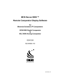
1
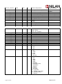
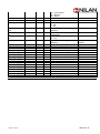
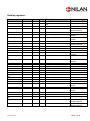
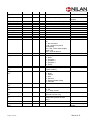
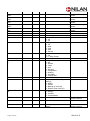
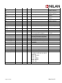
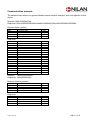
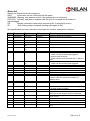
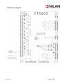
Installation and User Guide
2 602manual
CTS
by Nilan
User
VPM 360
Modbus
Version: 2.00 08-05-2014
Software-version: 2.20 →
a
The following information describes how to connect to Nilan CTS 602 controls by means of a
RS485 connection:
Table of Contents
Connection:....................................................................................................................................................... 2
Setup: ................................................................................................................................................................ 2
Supported functions: ....................................................................................................................................... 2
Register layout: ................................................................................................................................................ 3
Register groups ........................................................................................................................................ 3
Input registers:.......................................................................................................................................... 4
Holding registers: ..................................................................................................................................... 7
Communication example .............................................................................................................................. 11
Alarm list.......................................................................................................................................................... 12
See specification and user manual for each plant for a further description of alarms........................ 12
Revision history .............................................................................................................................................. 14
Connection diagram ...................................................................................................................................... 15
All rights reserved
Side 1 af 15
Connection:
The Modbus is connected to PIN 2,3,6 on CN7 placed next to the USB port of the printed circuit
board
Pin 1
Pin 2
Pin 3
Pin 4
Pin 5
Pin 6
12 VDC output
COM1 - RS 485 A - Modbus
COM1 - RS 485 B - Modbus
COM2 - RS 485 A - User panel
COM2 - RS 485 B - User panel
Ground
Setup:
Protocol
Modbus (RTU mode), see http://www.modbus.org/specs.php
Node address
Device type
Default 30, Address is selectable between 1 and 247
To be changed I SERVICE Menu.
CTS 602 is a Modbus slave
Baud rate
Databits
Stopbits
Parity
19.200
8
1
Even
Packet size
Max. 255 bytes
The communication speed and parameter can not be changed.
Supported functions:
Input and holding registers are supported.
All registers are 16 bit size.
The controller will respond to the below listed Modbus message functions only.
Please note that no other function codes are supported.
Function
Name
Description
03
04
16
All rights reserved
Read Holding Registers
Read Input Registers
Preset Multiple Registers
Read one or more holding registers
Read one or more input registers
Write one or more holding registers
Side 2 af 15
Register layout:
Register addresses are specified as decimal numerals.
Input registers are placed in the address area 30001..39999.
Holding registers are placed in the address area 40001..49999.
NOTE:
In the following tables, the register addresses applied in the MODBUS messages are without the
global offset. This means that if you read input register 100 with function code 04, you will get the
global address 30101.
NOTE:
All input registers can also be read as type holding register with function code 03 by adding the
offset value 10000 to the register address. No writes will be accepted in this range.
Register groups
The protocol data is grouped into the following address ranges with 100 registers in each group.
This applies to both input and holding register types:
Name
Device
Discrete I/O
Analog I/O
Time
Alarm
Week program
User functions
---Control
AirFlow
AirTemp
AirBypass
AirHeat
Compressor
Defrost
HotWater
CentHeat
AirQual
User panel
PreHeat
All rights reserved
Address
000
100
200
300
400
500
600
700
800
900
1000
1100
1200
1300
1400
1500
1600
1700
1800
1900
2000
2100
Description
Protocol and controller setup
Input / output bits (on/off)
Input / output words
Clock and calendar
Alarm and message handling
Calendar based programming
User input function selection
---System control and status
Ventilation control
Room temperature control
Exchanger bypass control
Inlet air heater control
Compressor operation control
Defrosting control
Hot water control
Central water heat control
(EK)
Air quality control (RH, CO2)
Display and keyboard
Intake air preheat / earth tube
VPM
x
x
x
x
x
x
x
VPL
x
x
x
x
x
x
x
VP
x
x
x
x
x
x
x
VGU
x
x
x
x
x
x
x
COMF
x
x
x
x
x
x
x
x
x
x
x
x
x
x
x
x
x
x
x
x
x
x
x
x
x
x
x
x
x
x
x
x
x
x
x
x
x
x
x
x
x
x
x
x
x
x
x
Side 3 af 15
x
x
x
x
Input registers:
Name
Address
Bus.Version
App.VersionMajor
000
001
Scale Unit
text
App.VersionMinor
002
text
App.VersionReleas
e
003
text
Input.UserFunc
Input.AirFilter
Input.DoorOpen
Input.Smoke
Input.MotorThermo
Input.Frost_Overht
Description
Used to plant type
Protocol version number
Software version - major (2
character ascii text)
Software version - minor (2
character ascii text)
Software version - release (2
character ascii text)
All plants
All plants
100
101
102
103
104
105
User function
Air filter alarm
Door contact
Fire/Smoke alarm
Motor thermo fuse
Heating surface frost / overheat
Input.AirFlow
106
Airflow monitor (guard)
Input.P_HI
Input.P_LO
Input.Boil
Input.3WayPos
Input.DefrostHG
Input.Defrost
107
108
109
110
111
112
High pressure switch
Low pressure switch
Hot water boiling
Hot water 3-way valve position
Hotgas defrost type selection
Defrost thermostat
Input.UserFunc_2
113
User function 2
All plants
VPM-Comfort-Comforti
VPM-Comforti
All plants
VPM-Comforti
VPL-VPM-CompactComfort-Comforti
VPL-VPM-CompactComfort-Comforti
All Plants
Not in use
VGU-VP-Compact
Not in use
Not in use
VPL-VPM-VGU-VPCompact
VPL-VGU-VPCompact-Comfort
Input.T0_Controller
Input.T1_Intake
200
201
100
100
°C
°C
Input.T2_Inlet
202
100
°C
Input.T3_Exhaust
203
100
°C
All plants
VPL-VPM-VGU-VPCompact
Inlet temperature (before heater) VPL-VPM-VPCompact-ComfortComforti
Room exhaust temperature
Comfort-Comforti
Input.T4_Outlet
204
100
°C
Outlet temperature
Input.T5_Cond
Input.T6_Evap
205
206
100
100
°C
°C
Condenser temperature
Evaporator temperature
Input.T7_Inlet
207
100
°C
Inlet temperature (after heater)
All rights reserved
All plants
All plants
Controller board temperature
Fresh air intake temperature
Compact-ComfortComforti
VPL-VPM-VP-Compact
VPL-VPM-VGU-VPCompact
VPL-VPM-VPCompact-ComfortComforti
Side 4 af 15
Input.T8_Outdoor
208
100
°C
Outdoor temperature
Comfort-Comforti
Input.T9_Heater
209
100
°C
Heating surface temperature
Input.T10_Extern
Input.T11_Top
Input.T12_Bottom
Input.T13_Return
Input.T14_Supply
Input.T15_Room
Input.T16
210
211
212
213
214
215
216
100
100
100
100
100
100
100
°C
°C
°C
°C
°C
°C
°C
-Input.RH
Input.CO2
217..220
221
222
100
%
ppm
External room temperature
Hot water top temperature
Hot water bottom temperature
EK return temperature
EK supply temperature
User panel room temperature
AUX temperature (sacrificial
anode)
(reserved)
Humidity
Carbon dioxide
VPL-VPM-ComfortComforti
All plants
VGU-VP-Compact
VGU-VP-Compact
VGU-VP
VGU-VP
All plants
VGU-VP-Compact
Alarm.Status
400
Alarm.List_1_ID
Alarm.List_1_Date
Alarm.List_1_Time
Alarm.List_2_ID
Alarm.List_2_Date
Alarm.List_2_Time
Alarm.List_3_ID
Alarm.List_3_Date
Alarm.List_3_Time
401
402
403
404
405
406
407
408
409
Control.RunAct
1000
Control.ModeAct
1001
Control.State
1002
All rights reserved
All plants
All plants
Alarm state bit mask
0x80 : Active
0x03 : Nb. of alarms
Alarm 1 - Code
Alarm 1 - Date
Alarm 1 - Time
Alarm 2 - Code
Alarm 2 - Date
Alarm 2 - Time
Alarm 3 - Code
Alarm 3 - Date
Alarm 3 - Time
All
Actual on/off state
0 : Off
1 : On
Actual operation mode
0 : Off
1 : Heat
2 : Cool
3 : Auto
4 : Service
Actual control state
0 : Off
1 : Shift
2 : Stop
3 : Start
4 : Standby
5 : Ventilation stop
6 : Ventilation
7 : Heating
8 : Cooling
9 : Hot water
10 : Legionella
11 : Cooling + hot water
12 : Central heating
13 : Defrost
All
All
All
All
All
All
All
All
All
All
All
All
Side 5 af 15
Control.SecInState
1003
AirTemp.IsSummer
1200
AirTemp.TempInlet
Set
AirTemp.TempCont
rol
AirTemp.TempRoo
m
AirTemp.EffPct
1201
100
°C
1202
100
°C
1203
100
°C
1204
100
%
AirTemp.CapSet
AirTemp.CapAct
1205
1206
100
100
%
%
Display.LED_1
Display.LED_2
Display.Text_1_2
Display.Text_3_4
Display.Text_5_6
Display.Text_7_8
Display.Attr_1_8
Display.Text_9_10
Display.Text_11_12
Display.Text_13_14
Display.Text_15_16
Display.Attr_9_16
2000
2001
2002
2003
2004
2005
2006
2007
2008
2009
2010
2011
All rights reserved
Sec
ascii
ascii
ascii
ascii
ascii
ascii
ascii
ascii
14 : Frost secure
15 : Service
16 : Alarm
Actual time in state
All
Summer state
0 : Off
1 : On
Inlet temperature request (T7
setpoint)
Actual value for controlled
temperature
Actual room temperature (T15
or T10)
Passive heat exchanger
efficiency
Requested capacity
Actual capacity
All
User panel indicator light
All plants
All plants
All plants
All plants
All plants
All plants
All plants
All plants
All plants
All plants
All plants
All plants
Text line 1 character 1-2
Text line 1 flags
Text line 2 character 9-16
Text line 2 flags
All
All
All
Compact-ComfortComforti
All plants
All plants
Side 6 af 15
Holding registers:
Name
Address
Bus.Address
0
Protocol node address (default = All plants
30)
Output.AirFlap
100
Air flap
Output.SmokeFlap
Output.BypassOpe
n
Output.BypassClos
e
Output.AirCircPump
Output.AirHeatAllo
w
Output.AirHeat_1
Output.AirHeat_2
Output.AirHeat_3
Output.Compressor
101
102
Fire/Smoke flap
Bypass flap open
103
Bypass flap close
104
105
Air heat circulation pump
Air heating selected
106
107
108
109
Air heater relays
--Compressor
Output.Compressor
_2
Output.4WayCool
110
Compressor 2
111
4-way valve
Output.HotgasHeat
Output.HotgasCool
Output.CondOpen
Output.CondClose
Output.WaterHeat
Output.3WayValve
Output.CenCircPu
mp
Output.CenHeat_1
Output.CenHeat_2
Output.CenHeat_3
Output.CenHeatExt
112
113
114
115
116
117
118
Hotgas valve - heat
Hotgas valve - cool
Air condenser active
Air condenser inactive
Hot water heater
Hot water 3-way valve
EK circulation pump
119
120
121
122
EK heater relays
--External radiator heat
Output.UserFunc
Output.UserFunc_2
123
124
User function active
--
Output.Defrosting
125
Defrost function active
VGU-VP
VGU-VP
VGU-VP
VPL-VP-CompactComfort
All plants
VPL-VGU-VP-CompactComfort
All plants
Output.ExhaustSpe
ed
Output.InletSpeed
200
100
%
Exhaust fan speed
All plants
201
100
%
Inlet fan speed
Output.AirHeatCap
202
100
%
Air heater capacity
VPL-VPM-VP-CompactComfort-Comforti
VPL-VPM-CompactComfort-Comforti
All rights reserved
Scale Unit
Description
Used to plant type
VPL-VPM-VGU-VPComfort-Comforti
VPM-Comforti
Compact-ComfortComforti
Compact-ComfortComforti
VPM-Comfort-Comforti
VPL-VPM-CompactComfort-Comfortit
VPM-Comforti
VPM-Comforti
VPM-Comforti
VPL-VPM-VGU-VPCompact
Not in use
VPL-VPM-VGUCompact
VPM
VPM
Compact
Compact
VGU-VP-Compact
Not in use
VGU-VP
Side 7 af 15
Output.CenHeatCa
p
Output.CprCap
203
100
%
Central heater capacity
VGU-VP
204
100
%
Compresor capacity
Output.EarthSpeed
205
100
%
Earth tube air intake fan speed
VPL-VPM-VGU-VPCompact
VPcCoB
Time.Second
Time.Minute
Time.Hour
Time.Day
300
301
302
303
ss
nn
hh
dd
Second
Minute
Hour
Day
All plants
All plants
All plants
All plants
Time.Month
Time.Year
304
305
mm
yyyy
Month
Year
All plants
All plants
Alarm.Reset
400
Clear one specific alarm code or All plants
all
0 : No command
1..99 : (reserved internal
commands)
101..199 : Clear alarm display
code 1..99
255 : Clear all alarms
Program.Select
500
Week program nb. select
0 : None
1 : Program 1
2 : Program 2
3 : Program 3
4 : Erase
All plants
Program.UserFunc
Act
Program.UserFunc
Set
600
All plants
Program.UserTime
Set
Program.UserVent
Set
602
User function active (See
“UserFuncSet”)
User function select
0 : None
1 : Extend
2 : Inlet
3 : Exhaust
4 : External heater offset
5 : Ventilate
Min User function period
All plants
Program.UserTemp
Set
Program.UserOffsS
et
604
°C
605
°C
Step User function ventilation
0 : Off
1..4 : Step number
User function temperature
(Extend function only)
User function
temperature(Offset function
only)
Program.User2Fun
cAct
610
Same as user function 1 above
VPL-VGU-VP-CompactComfort
All rights reserved
601
603
All plants
All plants
All plants
All plants
Side 8 af 15
Program.User2Fun
cSet
Program.User2Tim
eSet
Program.User2Vent
Set
Program.User2Tem
pSet
Program.User2Offs
Set
611
--
612
--
613
--
614
--
615
--
Control.Type
Control.RunSet
1000
1001
Do not use
All plants
Control.ModeSet
1002
Control.VentSet
1003
Control.TempSet
Control.ServiceMod
e
1004
1005
100
°C
Control.ServicePct
Control.Preset
1006
1007
100
%
AirFlow.AirExchMo
de
1100
AirFlow.CoolVent
1101
Step
Machine type select
User on / off select
0 : Off
1 : On
User operation mode select
0 : Off
1 : Heat
2 : Cool
3 : Auto
4 : Service
User ventilation step select
0 : Off
1..4 : Step number
User temperature setpoint
Service mode select
0 : Off
1 : Defrost
2 : Flaps
3 : Inlet
4 : Exhaust
5 : Compressor
6 : Heating
7 : Hot water
8 : Central heat
Service mode capacity
Request preset to factory
settings
0 : Ready
1 : Preset
2 : Backup (to user file)
3 : Restore (from user file)
Air exchange mode
0 : Energy
1 : Comfort
2 : ComfortWater
Cooling high ventilation step
AirTemp.CoolSet
1200
°C
Cooling temperature setpoint
select
VPL-VPM-VP-CompactComfort-Comforti
All rights reserved
Step
VPL-VGU-VP-CompactComfort
VPL-VGU-VP-CompactComfort
VPL-VGU-VP-CompactComfort
VPL-VGU-VP-CompactComfort
VPL-VGU-VP-CompactComfort
All plants
All plants
All plants
All plants
All plants
All plants
VPL-VPM-VGU-VP-
VPL-VPM-VP-CompactComfort-Comforti
Side 9 af 15
AirTemp.TempMinS
um
AirTemp.TempMin
Win
AirTemp.TempMax
Sum
AirTemp.TempMax
Win
AirTemp.TempSum
mer
1201
°C
Inlet temp. min. summer
1202
°C
Inlet temp. min. winter
1203
°C
Inlet temp. max. summer
1204
°C
Inlet temp. max. winter
1205
°C
Summer/winter limit
HotWater.TempSet
_T11
HotWater.TempSet
_T12
1700
°C
Top temperature setpoint
VGU-VP-Compact
1701
°C
Bottom temperature setpoint
VGU-VP-Compact
CentralHeat.HeatEx
tern
1800
°C
External heating offset from
room temperature setpoint
VPL-VP-CompactVPcCoB-
AirQual.RH_VentLo
1910
Step
All plants
AirQual.RH_VentHi
AirQual.RH_LimLo
AirQual.RH_TimeO
ut
1911
1912
1913
AirQual.RH_VentLo 1910 Step
Humidity low winter step select
Humidity high step select
Humidity limit for low ventilation
Humidity max. time on high
ventilation
AirQual.CO2_Vent
Hi
AirQual.CO2_LimL
o
AirQual.CO2_LimHi
1920
Step
CO2 high step select
All plants
1921
ppm
CO2 limit for normal ventilation
All plants
1922
ppm
CO2 limit for high ventilation
All plants
Display.KeyCode
2000
All rights reserved
100
Step
%
min
VPL-VPM-VP-CompactComfort-Comforti
VPL-VPM-VP-CompactComfort-Comforti
VPL-VPM-ComfortComforti
VPL-VPM-ComfortComforti
VPL-VPM-VP-CompactComfort-Comforti
All plants
All plants
User panel keypress
All plants
Combined value with one bit for
each key
0x01 : ESCAPE
0x02 : UP
0x04 : DOWN
0x08 : ENTER
0x10 : OFF
0x20 : ON
Side 10 af 15
Communication example
The sample shown below is a general Modbus communication example, and is not specific for this
device.
Request: 0b041000000e75a4
Response: 0b041cffff0000095008b0e4a80014000b000108e108f1ffff000f0002fff39f8e’
Request (Input register)
0x0b
0x04
0x1000
0x000e
0x75a4
Slave addr
Function code
Start addr
Quantity
CRC
1 byte
1 byte
2 bytes
2 bytes
2 bytes
Addr
Function code
NB bytes of data
Value1
Value2
Value3
Value4
Value5
Value6
Value7
Value8
Value9
Value10
Value11
Value12
Value13
Value14
CRC
1 byte
1 byte
1 byte
2 bytes
2 bytes
2 bytes
2 bytes
2 bytes
2 bytes
2 bytes
2 bytes
2 bytes
2 bytes
2 bytes
2 bytes
2 bytes
2 bytes
2 bytes
Response
0x0b
0x04
0x1c
0xffff
0x0000
0x0950
0x08b0
0xe4a8
0x0014
0x000b
0x0001
0x08e1
0x08f1
0xffff
0x000f
0x0002
0xfff3
0x9f8e
Request
0b03200000018f60
Response: 0b030200002045
Request (Holding register)
0x0b
0x03
0x2000
0x0001
0x8f60
Slave addr
Function code
Address
Quantity
CRC
1 byte
1 byte
2 bytes
2 bytes
2 bytes
Slave addr
Function code
Quantity
Value1
CRC
1 byte
1 byte
1 byte
2 bytes
2 bytes
Response
0x0b
0x03
0x02
0x0000
0x2045
All rights reserved
Side 11 af 15
Alarm list
Alarms are divided into these categories:
INFO:
Information can be confirmed with the same
WARNING: Warning, may become critical if the problem are not corrected
CRITICAL: Critically, operation is stopped until the fault is corrected and the alarm is
acknowledged
RS:
Restart (automatic restart when errors are OK, if selected by menu)
SC:
Self clearing (when receipted pending state again is OK)
See specification and user manual for each plant for a further description of alarms.
Code Text
0
1
Type
Subsystem
Function
NONE
CRITICAL
System
System
No alarm
Electrical faults (eg, Ur-circuit)
CRITICAL
CRITICAL
CRITICAL +
RS
CRITICAL +
SC
INFO
CRITICAL
System
AirFlow
Compressor
A WARNING has been critically
Fire thermostat
High or low pressure pressure switch
AirFlow
Inspection door open
Defrost
AirTemperature
CRITICAL +
SC
INFO + SC
INFO + SC
INFO + SC
CRITICAL
CRITICAL
CRITICAL
CRITICAL
AirTemperature
Defrosting time exceeded (compressor)
Plants without T9 sensor:
- Water coil freeze thermostat triggered
Systems with T9 sensor
- Water surface could not reach 20 ° C within 6
min.
Only plants with T9 sensor
- Water coil freeze thermostat triggered
Kettle over temperature (TMax +10 ° C)
Electric reheating overheating
Electric reheating lack of air flow
Ventilation Motor thermal switch
DHW Water boiling
Elected steered sensor is defect
Room temperature below the set minimum.
Winter protection (reduced ventilation) is
without effect.
Program startup / main loop
Program execution errors
2
3
4
NONE
HARDWAR
E
TIMEOUT
FIRE
PRESSURE
5
DOOR
6
7
DEFROST
FROST
8
FROST
9
10
11
12
13
14
15
OVERTEMP
OVERHEAT
AIRFLOW
THERMO
BOILING
SENSOR
ROOM LOW
16
17
INFO
INFO
System
System
18
SOFTWARE
WATCHDO
G
CONFIG
INFO
System
19
20
FILTER
LEGIONEL
INFO
INFO
AirFlow
HotWater
21
POWER
INFO
System
22
23
24
25
T AIR
T WATER
T HEAT
MODEM
INFO
INFO
INFO
INFO
AirTemperature
HotWater
CentralHeat
System
All rights reserved
CentralHeat
AirHeat
AirHeat
AirFlow
HotWater
AirTemperature
AirFlow
Database content changed - check settings
(eg after software update)
Air filter pressure switch or timer
Legionella Function not executed within the
time limit for the allowed number of attempts
Power outage longer than the backup time on
clock circuit
Air temperature errors
DHW temperature errors
Central heating temperature errors
Communication error modem (only CTS 600
G1)
Side 12 af 15
26
27
28
29
30
31
32
33
34
35
36
37
38
39
40
41
42
43
44
45
46
47
48
49
50
51
52
53
54
55
56
57
58
70
INSTABUS
T1SHORT
T1OPEN
T2SHORT
T2OPEN
T3SHORT
T3OPEN
T4SHORT
T4OPEN
T5SHORT
T5OPEN
T6SHORT
T6OPEN
T7SHORT
T7OPEN
T8SHORT
T8OPEN
T9SHORT
T9OPEN
T10SHORT
T10OPEN
T11SHORT
T11OPEN
T12SHORT
T12OPEN
T13SHORT
T13OPEN
T14SHORT
T14OPEN
T15SHORT
T15OPEN
T16SHORT
T16OPEN
ANODE
INFO
CRITICAL
CRITICAL
CRITICAL
CRITICAL
CRITICAL
CRITICAL
CRITICAL
CRITICAL
CRITICAL
CRITICAL
CRITICAL
CRITICAL
CRITICAL
CRITICAL
CRITICAL
CRITICAL
CRITICAL
CRITICAL
CRITICAL
CRITICAL
CRITICAL
CRITICAL
CRITICAL
CRITICAL
CRITICAL
CRITICAL
CRITICAL
CRITICAL
CRITICAL
CRITICAL
CRITICAL
CRITICAL
INFO + SC
System
System
System
System
System
System
System
System
System
System
System
System
System
System
System
System
System
System
System
System
System
System
System
System
System
System
System
System
System
System
System
System
System
HotWater
71
90
EXCH INFO
SLAVE IO
Defrost
System
91
92
OPT IO
PRESET
INFO
CRITICAL +
SC
INFO + SC
INFO
All rights reserved
System
System
Communication errors network (CTS 600 G1)
Temperature sensor shorted
Temperature sensor disconnected
Temperature sensor shorted
Temperature sensor disconnected
Temperature sensor shorted
Temperature sensor disconnected
Temperature sensor shorted
Temperature sensor disconnected
Temperature sensor shorted
Temperature sensor disconnected
Temperature sensor shorted
Temperature sensor disconnected
Temperature sensor shorted
Temperature sensor disconnected
Temperature sensor shorted
Temperature sensor disconnected
Temperature sensor shorted
Temperature sensor disconnected
Temperature sensor shorted
Temperature sensor disconnected
Temperature sensor shorted
Temperature sensor disconnected
Temperature sensor shorted
Temperature sensor disconnected
Temperature sensor shorted
Temperature sensor disconnected
Temperature sensor shorted
Temperature sensor disconnected
Temperature sensor shorted
Temperature sensor disconnected
Temperature sensor shorted
Temperature sensor disconnected
DHW tank anode corroded and needs replacing
(The alarm is deactivated by lice or
disconnection)
Defrost time exceeded (exchanger)
(not relevant for the CTS 602)
Options Module missing
Error while writing or reload
installer settings (PRESET menu)
Side 13 af 15
Revision history
Version Software Date
Description
1
2
2.00.q
2.11.e
22-04-2009
11-05-2010
Initial version
Rearranged User Function data layout
Added User Function 2
3
2.12a
03-06-2011
Added Control. Preset selections Backup and Restore
4
2.16a
16-02-2012
5
2.20.b
16-11-2013
Added earth tube air intake temperature and fan speed (Plan type
VPcCoB),
Alarm.Reset, and 17 other setpoints from 1101 to 1922.
Added reading of input registers as type holding
Added preheater and alarm relay outputs
“Version” refers to the protocol data item named “Bus.Version”.
All rights reserved
Side 14 af 15
Connection diagram
All rights reserved
Side 15 af 15