1
Novell Confidential
Manual (ENU) 21 December 2004
Novell
Security Manager Powered by
Astaro
www.novell.com
USER GUIDE
February 25, 2005
Novell Confidential
Manual (ENU) 21 December 2004
Legal Notices
Novell, Inc. makes no representations or warranties with respect to the contents or use of this documentation, and specifically disclaims any express
or implied warranties of merchantability or fitness for any particular purpose. Further, Novell, Inc. reserves the right to revise this publication and to
make changes to its content, at any time, without obligation to notify any person or entity of such revisions or changes.
Further, Novell, Inc. makes no representations or warranties with respect to any software, and specifically disclaims any express or implied warranties
of merchantability or fitness for any particular purpose. Further, Novell, Inc. reserves the right to make changes to any and all parts of Novell software,
at any time, without any obligation to notify any person or entity of such changes.
You may not use, export, or re-export this product in violation of any applicable laws or regulations including, without limitation, U.S. export
regulations or the laws of the country in which you reside.
Copyright © 2005 Novell, Inc. All rights reserved. No part of this publication may be reproduced, photocopied, stored on a retrieval system, or
transmitted without the express written consent of the publisher.
Novell, Inc. may have intellectual property rights relating to technology embodied in the product that is described in this document. In particular, and
without limitation, these intellectual property rights may include one or more of the U.S. patents listed at http://www.novell.com/company/legal/
patents/ and one or more additional patents or pending patent applications in the U.S. and in other countries.
Novell, Inc.
404 Wyman Street, Suite 500
Waltham, MA 02451
U.S.A.
www.novell.com
Novell Security Manager Powered by Astaro User Guide
February 25, 2005
Online Documentation: To access the online documentation for this and other Novell products, and to get updates, see
www.novell.com/documentation.
Novell Confidential
Manual (ENU) 21 December 2004
Novell Trademarks
NetWare is a registered trademark of Novell, Inc. in the United States and other countries.
Novell is a registered trademark of Novell, Inc. in the United States and other countries.
SUSE is a registered trademark of SUSE LINUX AG, a Novell business.
Third-Party Materials
Astaro Security Linux and WebAdmin are trademarks of Astaro AG. Linux is a trademark of Linus Torvalds. All third-party trademarks are the
property of their respective owners.
Portions © Astaro AG. All rights reserved. Pfinztalstrasse 90, 76227 Karlsruhe, Germany (http://www.astaro.com). Portions © Kaspersky Labs.
Novell Confidential
Manual (ENU) 21 December 2004
Table of Contents
Contents
Page
1.Introduction to the Technology.............................................5
2.Installation.........................................................................12
2.1.System Requirements .....................................................13
2.2.Installation Instructions .................................................16
2.2.1.Software Installation ...................................................16
2.2.2.Configuring the Security System ..................................21
3.WebAdmin .........................................................................29
3.1.Info Box .........................................................................30
3.2.Tab List ...........................................................................30
3.3.Menus 31
3.3.1.The Status Light ...........................................................31
3.3.2.Selection Field ..............................................................31
3.3.3.The Selection Table ......................................................32
3.3.4.Drop-down Menus ........................................................33
3.3.5.Lists 34
3.4.Online Help .....................................................................35
3.5.Refresh ...........................................................................36
4.Using the Security System .................................................37
4.1.Basic Settings (System)...................................................39
4.1.1.Settings ........................................................................39
4.1.2.Licensing .....................................................................44
4.1.3.Up2Date Service ...........................................................48
4.1.4.Backup .........................................................................55
4.1.5.SNMP ...........................................................................62
4.1.6.Remote Syslog Server ..................................................64
4.1.7.User Authentication .....................................................66
4.1.7.1.RADIUS .....................................................................67
4.1.7.2.SAM – NT/2000/XP ...................................................72
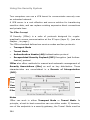
4.1.7.3.Active Directory/NT Domain Membership .................74
3
4.1.7.3.Active Directory/NT Domain Membership .................74
4.1.7.4.LDAP Server ..............................................................76
4.1.8.WebAdmin Settings ......................................................92
4.1.9.WebAdmin Site Certificate ...........................................95
4.1.10.High Availability .........................................................98
4.1.11.Shut down/Restart ...................................................105
4.2.Networks and Services (Definitions) .............................105
4.2.1.Networks ....................................................................106
4.2.2.Services .....................................................................113
4.2.3.Users ..........................................................................117
4.3.Network Settings (Network) .........................................121
4.3.1.Hostname/DynDNS ....................................................121
4.3.2.Interfaces ..................................................................122
4.3.2.1.Standard Ethernet Interface ...................................127
4.3.2.2.Additional Address on Ethernet Interface ................133
4.3.2.3.Wireless LAN ...........................................................135
4.3.2.4.Virtual LAN .............................................................145
4.3.2.5.PPPoE-DSL Connection ............................................150
4.3.2.6.PPTPoE/PPPoA-DSL Connections ............................155
4.3.2.7.PPP over Serial Modem Line ....................................160
4.3.3.Routing ......................................................................166
4.3.4.NAT/Masquerading.....................................................168
4.3.4.1.NAT .........................................................................168
4.3.4.2.Masquerading ..........................................................172
4.3.4.3.Load Balancing ........................................................173
4.3.5.DHCP Server ...............................................................176
4.3.6.PPTP VPN ...................................................................180
4.3.7.Accounting .................................................................186
4.3.8.Ping Check .................................................................188
4.4.Intrusion Protection ......................................................190
4.4.1.Settings ......................................................................190
4.4.2.Rules ..........................................................................192
4.4.3.Advanced ...................................................................197
4.5.Packet Filter ..................................................................199
4.5.1.Rules ..........................................................................199
4.5.2.ICMP ..........................................................................211
4.5.3.Advanced ...................................................................214
4.6.Application Gateways (Proxies).....................................220
4.6.1.HTTP ..........................................................................221
4.6.1.1.Content Filter (Surf Protection) ...............................229
4.6.2.DNS 241
4.6.3.SOCKS ........................................................................243
4.6.4.POP3 ..........................................................................245
4.6.5.Ident ..........................................................................250
4.6.6.SMTP ..........................................................................251
4.6.6.1.Content Filter ..........................................................260
4.6.6.2.Spam Protection ......................................................265
4.6.7.Proxy Content Manager ..............................................274
4.7.Virtual Private Networks (IPSec VPN) ...........................280
4.7.1.Connections ...............................................................288
4.7.2.Policies .......................................................................297
4.7.3.Local Keys ..................................................................301
4.7.4.Remote Keys ..............................................................304
4.7.5.L2TP over IPSec .........................................................307
4.7.6.CA Management .........................................................309
4.7.7.Advanced ...................................................................314
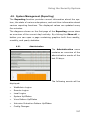
4.8.System Management (Reporting) ..................................317
4.8.1.Administration ...........................................................317
4.8.2.Virus ..........................................................................318
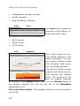
4.8.3.Hardware ...................................................................318
4.8.4.Network .....................................................................319
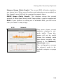
4.8.5.Packet Filter ...............................................................320
4.8.6.Content Filter .............................................................320
4.8.7.PPTP/IPSec VPN ........................................................321
4.8.8.Intrusion Protection ...................................................321
4.8.9.DNS 321
4.8.10.HTTP Proxy Usage ....................................................321
4.8.11.Executive Report ......................................................321
4.8.12.Accounting ...............................................................322
4.8.13.System Information .................................................324
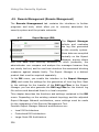
4.9.Remote Management (Remote Management) ................326
4.9.1.Report Manager (RM) .................................................326
4.10.Local Logs (Log Files) .................................................331
4.10.1.Settings ....................................................................331
4.10.2.Local Log File Query .................................................335
4.10.3.Browse .....................................................................336
4.10.3.1.Log Files ................................................................340
4.10.3.2.Error Codes ...........................................................344
4.11.Online Help .................................................................358
4.12.Exiting the Security System ........................................359
Glossary...............................................................................360
Index...................................................................................367
Notes ..................................................................................381
Table of Contents
4
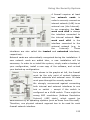
Installation
1.Introduction to the Technology
Before exploring the Novell Security Manager powered by Astaro
security system in detail, it may be helpful to take an overview of
network and security technology in general. In particular, it is
important to understand the serious risks that unprotected systems
face as well as where and how to deploy this security system to
mitigate these risks.
Networks
The Internet is already well established as a vital communications
medium and a key marketplace for both traditional and new services.
Since its inception, its size has multiplied, with domain name growth
between 1995 and 2003 reaching almost exponential proportions.
Computers on this worldwide network communicate using the Internet Protocol (IP), as well as various higher-level protocols such as
TCP, UDP, and ICMP. IP addresses uniquely identify each of the
computers reachable on the network.
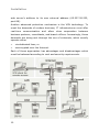
The Internet itself is a collection of smaller networks of various kinds.
When two or more networks are connected, a number of issues arise
which are dealt with by devices such as routers, bridges, and
gateways. A firewall is another such device, designed with security in
mind.
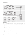
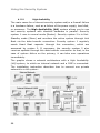
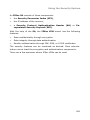
As a rule, three kinds of network meet at the firewall:
•
An external or Wide Area Network (WAN)
•
An internal or Local Area Network (LAN)
•
A De-Militarized Zone (DMZ)
An example configuration is shown on the next page.
5
Installation
The Firewall
One of the components in this security system is a firewall. The
characteristic tasks of a firewall connecting a WAN, LAN, and DMZ
are:
•
Protection against unauthorized access
•
Access control
•
Collection of audit trails
•
Protocol analysis
•
Reporting of security-related events
•
Concealing internal network structure
•
Separation of servers and clients using proxies
•
Guaranteeing information confidentiality
6
Installation
A firewall combines several network components in order to provide
these assurances. The following is a brief look at some of these tools
and their uses.
Network-Layer Firewalls: Packet Filters
As the name suggests, this component filters IP packets on the basis
of source and destination address, IP flags, and packet payload. This
allows an administrator to grant or deny access to services based on
factors such as:
•
The source address
•
The destination address
•
The protocol (e.g., TCP, UDP, ICMP)
•
The port number
The primary advantages of packet filters are their speed and their
independence of operating systems and applications in use behind the
firewall.
Advanced implementations of packet filters also inspect packets at
higher network layers. Such filters interpret transport-level information (such as TCP and UDP headers) to analyze and record all
current connections. This process is known as stateful inspection.
A stateful packet filter records the status of all connections, and
allows only those packets associated with a current connection to
pass. This is especially important for allowing connections from a
protected network to an unprotected one, but disallowing connections
in the opposite direction.
When a computer in the protected network establishes a connection
with an external server, the stateful packet filter will allow the
server’s response packets in to the protected network. When the
original connection is closed, however, the packet filter will block all
further packets from the unprotected network (unless, of course, they
have been explicitly allowed).
Application-Layer Gateways: Application Proxies
7
Installation
The second main kind of firewall is the application-layer gateway.
These gateways act as a middleman in connections between external
systems and protected ones. With such gateways, packets aren’t forwarded so much as translated and rewritten, with the gateway
performing the translation.
The translation process on the gateway is called a proxy server, or
proxy for short. Because each proxy serves only one or a few welldefined application protocols, it is able to analyze and log protocol
usage at a fine-grained level, and thereby offer a wide range of
monitoring and security options.
The analysis can be especially intensive at the application level,
because the application data transferred conforms to standardized
protocols. The firewall knows about and can inspect every aspect of
the data flow. This also means that small, manageable modules can
be used for each kind of data, which in turn means the system is less
prone to problems due to implementation errors.
For example, this security system includes the following proxies:
•
An HTTP proxy with Java, JavaScript and ActiveX
•
An SMTP proxy, which scans e-mails for viruses and controls email distribution
•
A SOCKS proxy which acts as a generic authenticating circuit-level
proxy for many applications
Application-level gateways have the advantage of allowing the
complete separation of protected and unprotected networks. They
ensure that no packets are allowed to move directly from one network
to the other. This results in reduced administration costs: as proxies
ensure the integrity of protocol data, they can protect all of the clients
and servers in your network, independent of brand, version, or
platform.
Protection Mechanisms
Some firewalls contain further mechanisms to ensure added security.
8
Installation
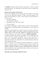
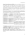
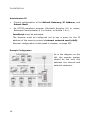
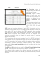
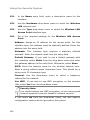
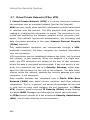
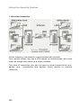
One such mechanism is supporting the use of private IP addresses in
protected networks through Network Address Translation (NAT),
specifically …
•
Masquerading
•
Source NAT (SNAT)
•
Destination NAT (DNAT)
This allows an entire network to hide behind one or a few IP
addresses, and hides the internal network topology from the outside.
This allows internal machines
to access Internet servers while
making
it
identify
individual
is
impossible
to
machines
from the outside.
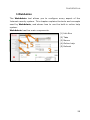
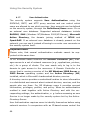
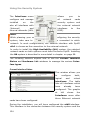
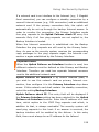
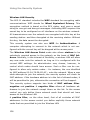
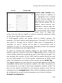
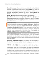
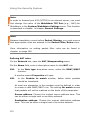
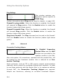
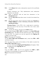
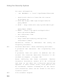
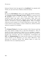
Using Destination NAT, it is
nevertheless possible to make
internal or DMZ servers available to the outside network for
specific services.
Example:
An
external
user
(see graphic on left) with the IP
address 5.4.3.2 sends a request from port 1111 to the
web server in the DMZ. The
user knows only the external IP
and port (65.227.28.232, port
88).
Using DNAT, the firewall changes the destination address of the
request to the internal address of the web server (192.168.2.99, port
80), and sends it to the web server. The web server then responds,
using its own internal IP address (192.168.2.99, Port 80), and sends
the reply back to the user. The firewall recognizes the packet from the
user’s address and changes the source address of the reply from the
9
Installation
web server’s address to its own external address (65.227.28.232,
port 88).
Another advanced protection mechanism is the VPN technology. To
meet the demands of modern business, IT infrastructures must offer
real-time
communication
and
allow
close
cooperation
between
business partners, consultants, and branch offices. Increasingly, these
demands are being met through the use of extranets, which usually
operate either
•
via dedicated lines, or
•
unencrypted over the Internet.
Each of these approaches has advantages and disadvantages which
must be balanced according to cost and security requirements.
10
Installation
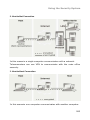
Virtual Private Networks (VPN) provide a cost-effective solution to
this problem: they can connect LANs over the Internet using encrypted connections, thus enabling secure, transparent, end-to-end
communication without the need for leased lines. This is especially
useful when an organization has many branch offices connected to the
Internet. IPSec technology provides a standard model for these
secure connections.
These secure connections can be used automatically, independent of
the data being transferred – this protects the data without requiring
extra configuration or passwords on the client systems.
At the other end of the connection, the data is transparently decoded and forwarded to the recipient in its original form.
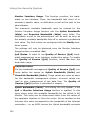
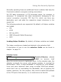
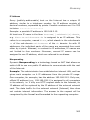
The Firewall component of this
security system is a hybrid of the
preceding protection mechanisms,
combining
the
advantages
of
each:
The Stateful Inspection Packet
Filter offers the platform-independent flexibility to define, enable,
and disable all necessary services.
The Proxies incorporated into this security system transform it into
an Application Gateway capable of securing vital services such as
HTTP, Mail and DNS. Further, the SOCKS proxy enables generic
circuit-level proxying for all proxy-aware applications.
VPN, SNAT, DNAT, Masquerading and static routing capabilities
make the firewall a powerful connection and control point on your
network.
11
Installation
2.Installation
The installation of this Internet security system proceeds in two main
steps: loading the software, and configuring the system parameters.
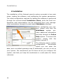
The initial configuration required for loading the software is performed
through the console-based Installation Menu, while the final configuration and customization can be performed from your management workstation through the web-based WebAdmin interface.
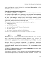
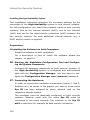
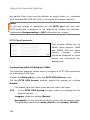
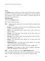
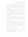
While configuring your system, please note that the
WebAdmin
system
pro-
vides additional information
and help through its Online
Help system. To access this
system,
simply
click
the
button marked ?.
The following pages contain
configuration
worksheets
where you can enter the
data (such as default gateways and IP addresses) you use to set up
your system. We recommend you fill these out as you configure the
system, and that you keep the worksheets in a safe place for future
reference.
12
Installation
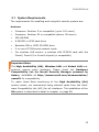
2.1. System Requirements
The requirements for installing and using this security system are:
Hardware
•
Processor: Pentium II or compatible (up to 100 users)
•
Processor: Pentium III or compatible (above 100 users)
•
256 MB RAM
•
8 GB IDE or SCSI hard drive
•
Bootable IDE or SCSI CD-ROM drive
•
2 or more PCI Ethernet network cards
•
For wireless LAN access: a wireless LAN PCMCIA card with the
Prism2, Prism2,5 or Prism3 chipset (or compatible)
Important Note:
The High Availability (HA), Wireless LAN, and Virtual LAN subsystems require extra hardware. Please check the Hardware
Compatibility List for Novell Security Manager powered by
Astaro, available at http://www.novell.com/documentation/
nsma51 for compatibility.
To make Heart Beat monitoring of the High Availability (HA)
system easier, we recommend using network cards from the Hardware Compatibility List (HCL) for all interfaces. The installation of the
HA system is described in detail in chapter on page 98.
13
Installation
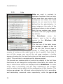
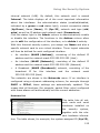
Administration PC
•
Correct configuration of the Default Gateway, IP Address, and
Subnet Mask
•
An HTTPS-compliant browser (Microsoft Explorer 5.0 or newer,
Netscape Communicator 6.1 or newer, or Mozilla 1.6+):
JavaScript must be activated.
The browser must be configured not to use a proxy for the IP
address of the security system’s internal network card (eth0).
Browser configuration is discussed in chapter on page 221.
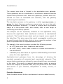
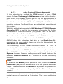
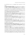
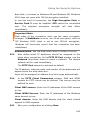
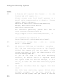
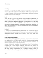
Example Configuration
As in the diagram on the
left, the security system
should be the only link
between the internal and
external networks.
14
Installation
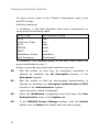
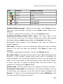
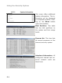
Address Table
Internal
network
interface
External
network
interface
DMZ
network
interface 1)
Network
interface for
the HA
system 2)
IP Address
Network Mask
Default Gateway
___.___.___.___
___.___.___.___
___.___.___.___
___.___.___.___
___.___.___.___
___.___.___.___
___.___.___.___
___.___.___.___
___.___.___.___
___.___.___.___
___.___.___.___
1)
The third and further network cards are optional.
2)
Network interface for the High Availability system.
15
Installation
2.2. Installation Instructions
What follows is a step-by-step guide to the installation process.
Attention:
The installation process will destroy all existing data on the hard disc!
Preparation
Before installation, please make sure you have the following items
ready:
•
the security system CD-ROM
•
the license key for the security system
•
the address table, with all IP addresses, network masks and
default gateway filled in
2.2.1.
Software Installation
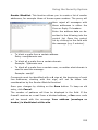
The first part of the installation uses the Installation Menu to configure basic settings.
The setup program will check the hardware of the system, and then
install the necessary software on your PC.
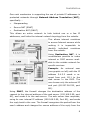
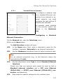
1.
Boot your PC from the CD-ROM Drive:
Select the appropriate installation mode for your computer.
Three pre-compiled kernel options are available for this purpose:
Default: Kernel for systems with a CPU.
SMP: Kernel for systems with several processors.
Classic: Kernel for systems with a CPU, in which the support for
APIC (Advanced Programmable Interrupt Controller) and ACPI
(Advanced Configuration and Power Interface) is disabled.
Since in older hardware components APIC and ACPI are often not
supported, we recommend using the Classic Kernel in this case!
16
Installation
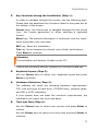
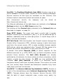
2.
Key Functions during the Installation (Step 1):
In order to navigate through the menus, use the following keys.
Please note the additional key functions listed in the green bar at
the bottom of the screen.
Cursor keys: Use these keys to navigate through the text boxes
(e.g., the license agreement or when selecting a keyboard
layout).
Enter key: The entered information is confirmed, and the installation proceeds to the next step.
ESC key: Abort the installation.
Tab key: Move between text boxes, entry fields, and buttons.
Press Enter to continue.
Attention:
The installation will destroy all data on the PC!
Confirm the following security question by clicking the F8 key.
3.
Keyboard Layout (Step 2):
Use the Cursor keys to select your keyboard layout and press
Enter to continue.
4.
Hardware Detection (Step 3):
The software will check the following hardware requirements:
CPU, size and type of hard drive, CD-ROM drive, network cards,
and IDE or SCSI controllers.
If your system does not meet the minimum requirements, the
installation will report the error and abort.
5.
Time and Date (Step 4):
Use the Cursor keys to select your country and press Enter to
confirm.
Use the Cursor keys to select your time zone and press Enter to
continue.
17
Installation
Next, enter the current time and date in the entry field. Use Tab
and the Cursor keys to switch between entry fields. Invalid
entries will be rejected.
Confirm your entries with the Enter key.
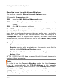
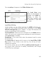
6.
Network Card Selection and Configuration (Step 5):
In order to use the WebAdmin tool to configure the rest of your
security system, you must now configure a card to be the internal network card (eth0).
Choose one of the available network cards from the list and
confirm your selection with the Enter key.
Next, define the IP address, network mask, and default
gateway for this network card.
Example:
Address: 192.168.2.100
Netmask: 255.255.255.0
You must enter a value in the Gateway field if you wish to use
the WebAdmin interface from a workstation outside the subnet
defined by the netmask. Note that the gateway itself must be
within the subnet.
For example, if you are using a network mask of 255.255.255.0,
the subnet is defined by the first three values of the address: in
this case, 192.168.2. If your administration computer is at, for
example, 192.168.10.5, it is not on the same subnet, and thus
requires a gateway to be configured here. The gateway router
must have an interface on the 192.168.2 subnet, and must be
able to contact the administration computer.
In our example, assume the gateway is at 192.168.2.1:
Gateway: 192.168.2.1
If the administration computer is on the same subnet as the
internal network card (in our example, if its address is
18
Installation
192.168.2.x) it does not need a gateway. In this case, enter the
following value here:
Gateway: none
Confirm your entries with the Enter key.
7.
License Agreement (Step 6):
Note:
Please read the license agreement carefully.
Press F8 to agree to the terms of the license.
8.
Final Notes (Step 7):
Attention:
Please read the notes and warnings presented during the
installation carefully. After confirming them, all existing data on
the PC will be destroyed!
If you wish to change your entries, press F12 to return to Step
1. Otherwise, start the installation process by pressing the F8
key.
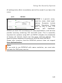
9.
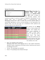
Installing the Software (Step 8):
The software installation process can take up to a couple of
minutes. You can follow the progress of the installation using the
four monitoring consoles:
There are four consoles available:
Main Installation (Alt + F1).
Interactive bash Shell 1 (Alt + F2).
Installation Log (Alt + F3).
Kernel Log (Alt + F4).
When the installation process completes, remove the CD-ROM
from the drive and connect the eth0 network card to the internal
network.
19
Installation
Except for the internal network card (eth0), the sequence of
network cards normally will be determined by PCI ID and by the
Kernel drivers.
The sequence of network card names may also change if the
hardware configuration is changed, especially if network cards
are removed or added.
10. Reboot the System:
Reboot the security system by pressing Ctrl + Alt + Del or the
Reset button.
During the boot process, the IP addresses of the internal network
cards are changed. The Install Routine console (Alt + F1) may
display the message No IP on eth0 during this time.
After the security system has rebooted (a process which, depending
on hardware, can take up to five minutes), ping the IP Address of the
eth0 interface to ensure it is reachable.
If no connection is possible, please check for the following possible
problems.
Error:
The security system is not reachable from the internal network.
Possible Causes:
20
Installation
•
The IP address of the security system is incorrect
•
The IP address of the client computer is incorrect
•
The default gateway on the client is incorrect
•
The network cable is connected to the wrong network card
•
All network cards are connected to the same hub
Note:
If you connect to the Internet through a DSL connection, please read
the installation instructions at
http://www.novell.com/documentation/nsma5.
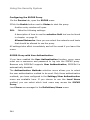
2.2.2.
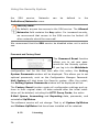
Configuring the Security System
The rest of the configuration will use the WebAdmin interface,
accessed through a standard web browser (e.g., MS Internet
Explorer) from your administration PC:
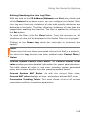
1Start your Browser and open WebAdmin:
Before you can access the WebAdmin interface, you must make
sure that your browser is configured correctly. Please see in
chapter on page 221 for more details.
Once your browser is correctly configured, start it and enter the
management address of the security system (the internal IP
address configured for eth0) as follows: https://IP Address.
(In
the
example
from
step
6
above,
this
would
be
https://192.168.2.100)
A security notice will appear. When you generate a certificate
for WebAdmin in a later step, this notice will disappear.
Further information on generating and installing certificates can
be found in chapter on page 95.
For now, simply accept the security notice by clicking the Yes
button.
21
Installation
The first time you start WebAdmin, two windows will open: the
first contains the License Agreement, and the second is used
for Setting System Passwords.
11. Complete the License Agreement:
In the License Agreement window, accept the terms of the
license by clicking the I agree to the terms of the license
selection box.
Note:
Please read the terms of the license carefully.
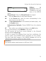
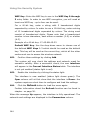
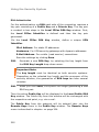
12. Set the System Passwords:
In the Setting System Passwords window, enter the passwords for the Internet security system.
Security Note:
Use a secure password! Your name spelled backwards is,
for example, not a secure password – while something like
xfT35$4 would be.
You will only be able to start WebAdmin once you have entered
passwords for the functions listed below. Enter the password for
each service, and then re-enter it in the text field labeled
Confirm. The usernames are pre-defined, and cannot be
changed.
WebAdmin user: access to WebAdmin
This user is called admin.
Shell Login user: access to SSH
This user is called loginuser.
Shell Administrator user: administrator privileges in the entire
security system.
This user is called root.
22
Installation
Security Note:
Use different passwords for the Shell Login and Shell
Administrator users.
Configuration Manager User (optional): You need this password, if you wish to configure the Security system with the
Configuration Manager.
Boot Manager (optional): If set, the password will prevent unauthorized users from changing boot-time parameters.
Confirm the entered passwords by clicking Save.
13. Log in to WebAdmin:
User: admin
Password: Password of the WebAdmin user
Please note that passwords are case-sensitive!
Click Login.
Note:
Please follow steps through in the order listed below.
23
Installation
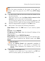
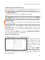
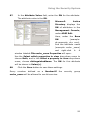
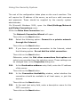
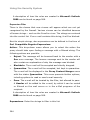
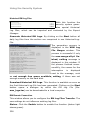
14. Uploading the License Key:
In the System tab, open the Licensing menu and upload the
license key under the License File window.
Note:
When using a license with the High Availability (HA) option,
you must import the License Key to both security systems
(Normal and Hot Standby mode).
For more information on Licensing, see chapter on page 44.
15. Configure Basic Settings:
In the System tab, open the Settings menu and enter the following setting:
Administrator E-Mail Addresses: Enter the e-mail address of
the administrator here.
You can find further information about these functions in chapter
on page 39.
In the Network tab, open the Hostname/DynDNS menu and
enter the following settings in the General System Settings
window:
Hostname: Enter the Hostname for this security system.
A domain name may contain alphanumeric characters, periods,
and hyphens. The end of the name must be a valid top-level
domain, such as “com”, “de”, or “org”. The Hostname will be
included in all Notification E-Mails.
Save the settings by clicking Save.
24
Installation
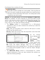
16. Configure the internal Network Interface (eth0):
In the Network tab, open the Interfaces menu and check the
settings for eth0 network card.
The settings for this network card are based on the information
entered during the software installation. After starting the
security system, they are shown in the Current Interface
Status window.
If you wish to
change settings
for this card, for
example
changing
the
configured name, please open the Edit Interface window by
clicking the edit button and make these changes now.
Attention:
If you change the IP address of the eth0 network card, you
will be locked out of WebAdmin.
The configuration of network cards and virtual interfaces is
described in chapter on page 122.
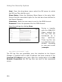
17. Configure the internal Network:
In
the
Definitions
tab,
open
the
Networks
menu and check the settings for the internal network. Three
logical networks were defined during installation based on your
settings for the internal network card (eth0):
The interface Internal (Interface), consisting of the defined IP
address (example: 192.168.2.100) and the host network mask
255.255.255.255.
25
Installation
The broadcast network Internal (Broadcast), consisting of the
broadcast address (example: 192.168.2.255) and the host network mask 255.255.255.255.
The internal network Internal (Network), consisting of the defined IP address (example: 192.168.2.0) and the defined network mask (example: 255.255.255.0).
Defining new Networks is described in chapter on page 106.
18. Configure the external Network Card:
In the Network tab, open the Interfaces menu and configure
the interface to be used to connect to the external network
(Internet). The choice of interface and the required configuration
depend on what kind of connection to the Internet you will be
using.
The configuration of network cards and virtual interfaces is
described in chapter on page 122.
19. Define Masquerading Rules:
If you wish to use private IP addresses for your internal network
and wish to connect directly (without proxies) to the Internet,
you can now establish the relevant rules in the Network/
NAT/Masquerading menu.
More information about DNAT, SNAT and Masquerading can
be found in chapter on page 168.
IP routing entries for networks directly connected to the security
system’s network cards (Interface Routes) will be added automatically.
If required, you can also define routing entries manually using
the Routing menu. This will, however, usually only be necessary
in complex network environments.
26
Installation
20. Configure the DNS Proxy:
In order to speed up name resolution, you can specify a local
DNS name server (or one provided by your ISP) in the
Proxies/DNS menu. Otherwise, the security system will automatically use the root name servers.
If you wish to use the proxy, you should configure the DNS
Proxy settings now.
More information about configuring the DNS Proxy can be found
in chapter on page 241.
21. Connect other Networks:
If you wish to connect other internal networks to the security
system, attach their cables now.
22. Configure the HTTP Proxy:
If computers on the internal network should use the HTTP proxy
to connect to the Internet, open the HTTP menu in the Proxies
tab and click Enable.
It might be necessary to configure the browsers to allow the
computers in the internal network to access the Internet by
using the HTTP proxy afterwards - e.g. if the proxy was configured for the standard operation mode.
The configuration of the HTTP proxy is described in more detail
in chapter on page 221.
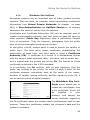
23. Configure the Packet Filter:
In the Rules menu under the Packet Filter tab, you can
establish packet filtering rules.
By default, all packets are filtered until you explicitly enable
certain services. New rules are added to the bottom of the list,
and are inactive until explicitly enabled. The rules are processed
starting with the first and moving down the list, stopping at the
first applicable rule. To activate a rule, click the status light once
– the status light will turn green.
27
Installation
Please note that, because the security system uses Stateful
Inspection, only the connection-building packets need be
specified. All response packets will automatically be recognized
and accepted.
Configuring the Packet Filter is described in chapter on page
199.
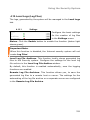
24. Debug Packet Filter Rules:
With the Packet Filter Live Log function In the Packet Filter/
Advanced menu, you can see which packets the packet filter is
filtering. If you have problems after installing your security
system, this information can be helpful in debugging your
filtering rules.
The Packet Filter Live Log function is described in chapter on
page 214.
25. Install System and Virus Scanner Updates:
You should download and install the latest System Up2Dates as
soon as possible.
If you have a license for the Virus Protection option, you
should also run the Pattern Up2Date system.
The Up2Date Service option is described in chapter
on page
48.
When you’ve completed these steps, the initial configuration of your
security system is complete. Click the Exit tab to leave WebAdmin.
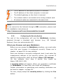
Problems
If you have problems completing these steps, please visit the Novell
Support Forum at:
http://support.novell.com/forums/2sm.html
28
Installation
3.WebAdmin
The WebAdmin tool allows you to configure every aspect of the
Internet security system. This chapter explains the tools and concepts
used by WebAdmin, and shows how to use the built-in online help
system.
WebAdmin has five main components:
(1) Info Box
(2) Tabs
(3) Menus
(4) Online help
(5) Refresh
29
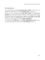
Installation
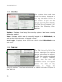
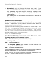
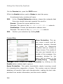
3.1. Info Box
The system time and time
zone are always displayed in
the top left-hand corner of
the screen. If you roll the
mouse over the time display,
the Info Box will appear, containing the following information:
Uptime: Displays how long the security system has been running
without a restart.
User: Displays which user is currently logged in to WebAdmin, as
well as the client the user is logged in from.
Last Login: Displays when and from which client WebAdmin was
last used.
3.2. Tab List
The Tab List on the left of the
screen organizes the various
menus according to subject.
To list the menus contained
under
a
simply
click
subject
the
heading,
tab:
the
available menus will appear
below.
chapter
For
5,
ease
of
use,
“Using
the
Security system”, has been structured to match the order of topics in
the Tab List.
30
Installation
3.3. Menus
Every function of the security system has its own separate menu in
WebAdmin. This chapter describes the tools and displays used in the
configuration menus.
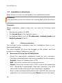
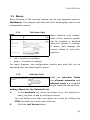
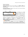
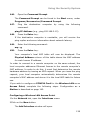
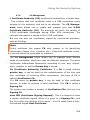
3.3.1.
The Status Light
Many features and subsystems of the security system
can be enabled or disabled
while the system is running.
A status light displays the
current status of such subsystems:
•
red = Function is disabled
•
green = Function is enabled
For many features, the configuration options and tools will not be
displayed until the status light is green.
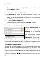
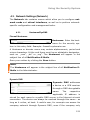
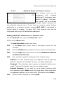
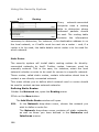
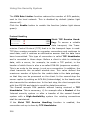
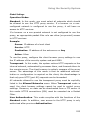
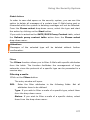
3.3.2.
Selection Field
With the
selection
fields
the allowed networks and
allowed users are assigned
to the functions and services.
Adding Objects to the Selected List:
1.
In the Available list, select the object (e.g., the network or
user) you wish to add by clicking its name.
You can select more than one object at a time by holding the
CTRL key while you make your selection.
2.
Click the Left Arrow button.
31
Installation
The names you selected in the Available window will be moved
to the Selected window.
Removing Objects from the Selected List:
1In the Selected list, choose the objects (networks or users) you
wish to remove by clicking them.
Again, you can select more than one object at a time by holding
the CTRL key while you make your selection.
3.
Click the Right Arrow button.
The objects will be moved back to the Available window.
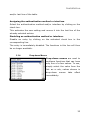
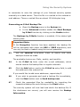
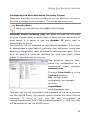
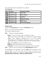
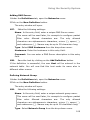
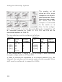
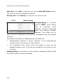
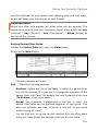
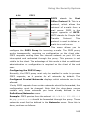
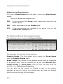
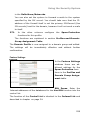
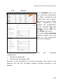
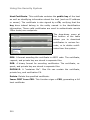
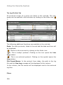
3.3.3.
The Selection Table
Use the selection table to
assign the corresponding authentication method or an
interface to the functions
and services.
The
authentication
(Menu
method
System/User
Au-
thentication) and the interfaces
(Menu
Network/
Interfaces) must first be configured by the administrator. The
picture above shows a selection table for interfaces. The picture below
shows a table for the selection of authentications.
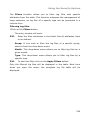
The functions with the entries:
The functions are only activated if the corresponding entry has been
selected. The position of the entry is displayed in the left column. Use
the buttons in the right column to change the order of the entries.
Clicking on the buttons
or
moves the respective entry one line up
or
moves the respective entry in the first
and/or one line down.
Clicking on the buttons
32
Installation
and/or last line of the table.
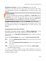
Assigning the authentication method or interface:
Select the authentication method and/or interface by clicking on the
check box.
This activates the new setting and moves it into the last line of the
already selected entries.
Disabling an authentication method or interface:
Disable an entry by clicking on the activated check box in the
corresponding line.
The entry is immediately disabled. The functions in this line will then
be no longer available.
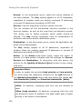
3.3.4.
Drop-down Menus
Drop-down menus are used to
configure functions that can have
only one of a few values. To use,
simply select the value from the
list: as a rule, values chosen in
drop-down
menus
take
effect
immediately.
33
Installation
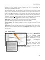
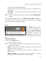
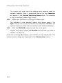
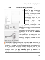
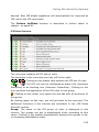
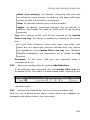
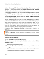
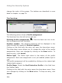
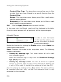
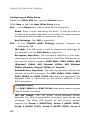
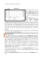
3.3.5.
Lists
Lists are used, in contrast, to
configure functions that not only
allow more than one value to be
configured, and where the listed
objects do not need to be first
defined by the administrator. In
some instances, the order of the
configured values is also relevant.
Each list can contain many pages
of values, and each page displays
ten entries.
The
Interfaces
menu,
for
instance, uses a list to allow
access
to
the
Wireless
LAN
Access Point.
The first row of the table shows
the number of pages in the list
on the left (the current page is
shown in white) and the total
number of entries on the right (next to the # symbol). Note that, if
you roll the mouse over one of the red page numbers, a tooltip
appears showing the first and last entries on that page (see picture at
right). This can help to navigate quickly between pages.
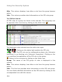
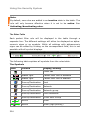
The second row contains tools to control the display of the list. Note
that these do not change the configuration information, but rather the
way in which these entries are displayed within WebAdmin. In cases
where order is important, only the order indicated by the numbers
next to entries has an effect on the configuration of the function. The
buttons
and
in the left-hand column display the list in ascending
and descending numerical order respectively, while the
34
and
Installation
buttons in the middle column display the list in ascending or
descending alphabetical order.
The functional order, as indicated by the numbers to the left of each
entry, can be adjusted using the buttons in the right-hand column. A
click on the
or
button in this column will move the entry one row
up (i.e., towards 1) or down (towards the end of the list) respectively.
Similarly, you can move an entry to the very beginning or end of the
list by clicking the
or
buttons in this column, respectively.
Add entry: Type a value in the text-entry field and click Add.
The new value will appear in the last row of the table.
Delete entry: By double-clicking an entry, you can remove it from
the list.
Edit entry: If you click an entry once, it will appear in the entry field.
Edit the entry as desired and click the Replace button to put it back
into the list.
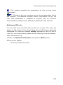
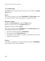
3.4. Online Help
Every menu in WebAdmin
has
an
Online
Help
screen which provides a
short explanation of the
available
configuration
options.
You can open the help
screen by clicking the ?
button at the top righthand corner of the screen.
35
Using the Security System
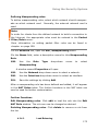
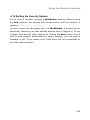
3.5. Refresh
To load the menu again,
click the Refresh button.
Don’t
use
the
Refresh
button of the tool bar of
your browser to actualize
the menu – otherwise you
are logged-off the session
and have to log in again
under
the
WebAdmin
configuration tool!
36
Using the Security System
4.Using the Security System
We have already seen
the web-based configuration tool WebAdmin in
action during the installation
process.
This
chapter will describe how
to
use WebAdmin to
control and monitor your
security
system
on
a
day-to-day basis.
The specific settings, what they do, and how to change them will be
described step-by-step. Please look to chapter
for a more general
description of how to use the tools provided by the WebAdmin
interface.
Please remember that the goal in configuring a security system like
this should be to enable only the features necessary for correct
functionality. In general, you should restrict in- and outbound connections to those explicitly required.
Tip:
Draw up a plan of your network and determine which computer is to
have access to which services before configuring the security
system. This will simplify the configuration process and save you a lot
of time.
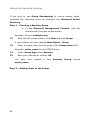
Configure the system as follows:
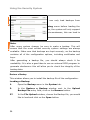
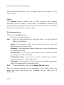
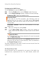
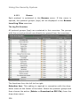
1Define all the required networks and hosts.
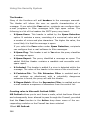
4.
Define the necessary services.
5.
Define the system rules and proxies.
Starting WebAdmin:
37
Using the Security System
1Start your browser and enter the address of the Security system
(i.e., the address of the eth0 interface) as follows:
https://IP Address.
In our example from step 6 of the installation instructions in
chapter , this would be https://192.168.2.100.
If you have not yet generated a Certificate for your WebAdmin
site, a Security notice will appear.
More information on how to install a certificate is available in
chapter on page 95.
6.
Click the Yes button on the security notice to continue.
7.
Log in to WebAdmin.
User: admin
Password:
password
the
of
the
WebAdmin user.
Both entries are case-sensitive!
8.
Click Login.
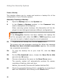
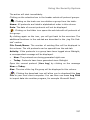
Another administrator is already logged-in:
If
another
administrator
is
already logged in to
WebAdmin, a notice
will
appear
on
screen. The IP address
shows
you
which computer the other administrator is using.
The kick function allows you to end the other administrator’s
session.
In the Reason field, type a reason for ending the other user’s
session and click Login.
38
Using the Security System
You are now logged in, and can use the WebAdmin to manage the
system.
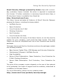
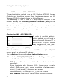
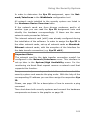
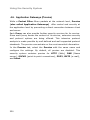
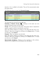
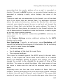
4.1. Basic Settings (System)
The menus under the System tab allow you to configure and manage
the basic settings of your security system.
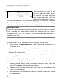
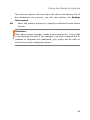
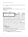
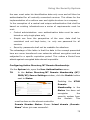
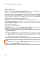
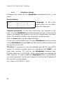
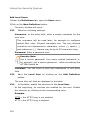
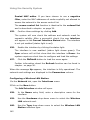
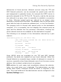
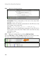
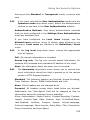
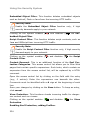
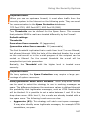
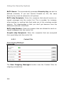
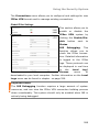
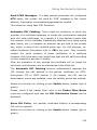
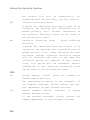
4.1.1.
Settings
Administrator Contact
E-Mail Addresses: Whenever
certain important events occur,
such as portscans, failed logon
attempts, or reboots, as well as whenever the self-monitor or Up2Date systems generate alerts or reboots, the security system will
send a notification e-mail to the administrator through the e-mail
addresses entered into the ordered list. At least one e-mail address
must be present; otherwise the E-Mail Reporting function will be
disabled.
To add a new e-mail address, enter it in the entry field and click Add.
Please see chapter on page 34 to learn more about the functions of
the ordered list.
Important Note:
Notification E-Mails can only be sent to the administrator when the
DNS Proxy is enabled and configured (chapter
on page 241), or
when the SMTP menu (chapter on page 251) has been configured
with a route for incoming e-mails.
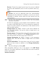
Use external Indicators: This option is only available on appliance
systems with an attached LCD indicator. This option allows you to
turn the LCD display on or off.
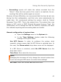
Time Settings
39
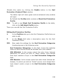
Using the Security System
This menu can be used to set
the time and date of the security system. The date and time
can be set manually with the
help of the drop-down menu or
can be automatically synchronized using the NTP-server (Network
Time Protocol). Please note that important changes in the time setting
will appear as gaps in the Reporting and Logging.
Important Note:
We do not recommend changing the system time for daylight savings
time. Instead, we recommend setting the system clock to Central
European Time (CET). In summer, this corresponds to a deviation of
less than one hour.
When system time settings are changed, the following “time warp”
effects may be noticeable:
Moving forward (e.g., standard time to daylight saving time)
•
The timeout for WebAdmin will expire and your session will no
longer be valid.
Time-based reports will have no data for the skipped hour. In most
graphs, this time period will appear as a straight line in the
amount of the old value.
•
Accounting reports will contain values of 0 for all variables
during this time.
Moving backward (e.g., daylight saving time to standard time)
•
There are already log data for the corresponding span of time in
the time-based reports that for system purposes come from the
future: These data will not be overwritten.
•
Log data will be written as normal when the time point before the
reset is reached again.
•
Most diagrams will display the values recorded during this period
as compressed.
40
Using the Security System
•
Accounting reports will retain the values recorded from the
“future”. Once the time point of the reset is re-reached, the accounting files will be written again as normal.
Because of these difficulties, we recommend that the time be set only
during the first configuration, and that only minor adjustments be
made later. We recommend setting the system clock to Central
European Time (CET). This is the original time. The system then runs
always in CET, not in in CEST (Central European Summer Time). We
recommend, not to change the time for summer, especially not when
the collected reporting and accounting data are treated.
Manual configuration of system time:
a.
b.
Open the Settings menu in the System tab.
In the Time Settings window make the following
settings in the given order:
Use NTP Server: In order to configure the system clock
manually, please ensure that No NTP Server is selected here. In
this case, the Please select drop-down menu will be displayed.
If a NTP Server is selected, select No NTP Server from the
drop-down menu.
Time Zone: Now select the time zone.
Note:
Changing the timezone will only change the current system time
if you are using an NTP server to control time settings.
Set Time: Enter the current date and time here.
41
Using the Security System
Important Note:
Take note of the issue date of your License Key. If this date is
after the current date set on the security system, the license will
be deactivated.
The 30-day Evaluation License will not automatically activate.
9.
Click the Save button to save these settings.
The time settings of the security system will now be updated.
Synchronizing system time with NTP Server
Before the system clock of the Internet security system can be
synchronized with an external server, this server must be defined as
NTP Server. The NTP Server will be defined as a network consisting
of only one computer.
The definition of networks is covered in greater detail in chapter
on
page 105. If the NTP server has already been defined, please begin
with step .
1Open the Networks menu in the Definitions tab.
2In the Name entry field enter a distinct Name.
Allowed characters are: Letters of the alphabet, digits from 0 to 9,
hyphen, space, and underscore characters. The name must be fewer
than 39 characters long.
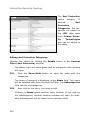
10.
Now enter the IP Address of the NTP Server.
11.
In the Subnet Mask entry field, enter the network mask
255.255.255.255.
12.
Now confirm your settings by clicking on the Add button.
WebAdmin will now check your entries for semantic validity.
Once accepted, the new network will appear in the network
table.
13.
42
Open the Settings menu in the System tab.
Using the Security System
14.
In the Time Settings window make the following settings in
the given order:
Time Zone: Now select the time zone.
Use NTP Server: Select the NTP Server here.
The system clock of the Internet Security system will be synchronized
with the external NTP server every hour.
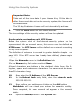
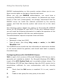
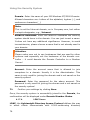
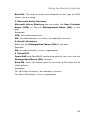
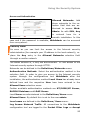
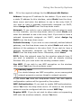
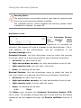
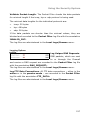
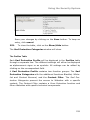
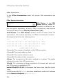
SSH (Shell Access) Settings
Secure Shell (SSH) is a textbased access mode for the
security system intended only for advanced administrators. In order
to access this shell, you will need an SSH Client, which comes
standard
with
most
Linux
distributions.
For
MS-Windows,
we
recommend Putty as SSH Client. Access through SSH is encrypted,
and cannot be read by eavesdroppers.
The Shell Access function is enabled by default, once you have
entered a password for the configuration through the Configuration
Manager in the Setting System Passwords window.
If
you
wish
to
access
the
security system through SSH,
the SSH Status light must be
enabled
(status
light
shows
green).
The SSH protocol uses name resolution (valid name server) if no
valid name servers are found, SSH access attempts will time out. The
time-out takes about a minute. During which time the connection
seems to be frozen or failed. Once the time-out has expired, the connection process continues without further delay.
You must also add the networks allowed to access the SSH service in
the Allowed Networks selection field.
In
order
to
ensure
a
seamless installation process, the Allowed networks field contains
the Any option by default, this means that any computer can access
43
Using the Security System
the
SSH
service.
Networks
can
be
defined
in
the
Definitions/Networks menu.
Security Note:
By default, anyone has access to the SSH service. The Allowed
Networks field contains the Any option. For increased security,
we recommend that access to the SSH service be limited. All
other networks should be removed!
We recommend that the SSH service be disabled when not in active
use.
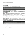
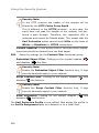
Password and Factory Reset
The Password Reset function
allows you to set new passwords for the Security system.
If you log in to the WebAdmin
configuration tool for the first time after this action, the Setting
System Passwords window will be displayed. This allows you to set
optional passwords, such as the Configuration Manager Password.
Halt System will shut down the Security system. After the restart,
the Setting System Passwords window will be displayed at first.
The Factory Reset function resets all configuration settings and options to their original state. All data entered after the initial installation will be deleted, including the HTTP Proxy Cache, the entire
E-Mail Queue, Accounting and Reporting data, passwords, and
uninstalled Up2Dates.
The software version will not change. That is, all System Up2Dates
and Pattern Up2Dates that have been installed will be retained.
4.1.2.
44
Licensing
Using the Security System
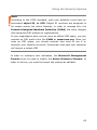
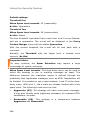
Novell Security Manager powered by Astaro ships with a sevenday evaluation license included. No action is required to implement
this license. If further evaluation is necessary beyond seven days, a
90-day demo license is available from Novell at:
http://download.novell.com
The demo license activates all features of Novell Security Manager
powered by Astaro, including the base product:
•
Up2Date Service
•
Spam Protection
•
Virus Protection for E-Mail
•
Phishing Protection
•
Surf Protection
•
Virus Protection for Web
If you decide after the expiry of the demo license, to use the security
system for your company, you’ll need the base license. This base
license can then be completed with up to four functions and security
packages.
This base license and the four functions and security packages contain
the following modules:
•
Base license: Packet Filter, VPN Gateway and Intrusion Protection
•
Maintenance & Support: Up2Date Service
•
High Availability
•
Secure E-Mail Subscription: Spam Protection, Virus Protection for
E-Mail, Phishing Protection
•
Secure Web Subscription: Surf Protection, Virus Protection for
Web
The price of the company version depends on the size of the network
to be protected, the scope of support and the modules, subscribed to
in addition to the base license.
For more information, please visit our website under:
http://www.novell.com/products/securitymanager
45
Using the Security System
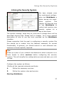
Licensing the Internet security system:
In order to license the Internet security system, you need a valid
license string on the local host, so that you can enter it to the
Internet security system through the WebAdmin configuration tool.
Note:
When using a license with the High Availability (HA) option, you
must enter the License strings to both security systems (Normal
and Hot Standby mode).
1Open the Licensing menu in the System tab.
2Enter the license string(s) in the License Strings entry field.
15.
Click on the Save button.
The system will require between 30 and 60 seconds to process this
information. After successful registration, the Installed Licenses
window will contain the details of your license.
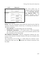
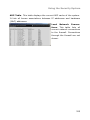
Installed Licenses
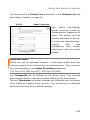
After successful registration of the Internet security system, the
Installed Licenses window will show the details of your license.
Licensed Users (IPs)
The functions in this window are used for licenses that do not allow
for an unlimited number of users (IP addresses).
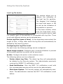
View current User (IP) Listing: The table contains all IP addresses
that are relevant for the licensing. The current user table is always
loaded when this menu is opened.
The table will also be displayed if the license is an unlimited version.
46
Using the Security System
Reset User (IPs) Listing: If you wish to reconfigure the internal
network, you can reset the user table by this action. Then there is a
reboot - the system will shut down completely and reboot.
This action is enabled by clicking on the Start button.
47
Using the Security System
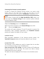
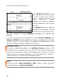
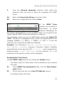
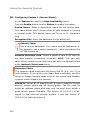
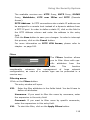
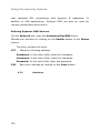
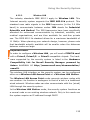
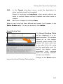
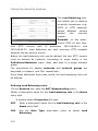
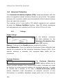
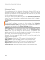
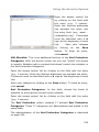
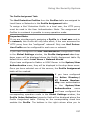
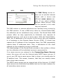
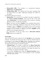
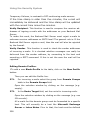
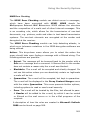
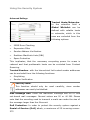
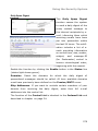
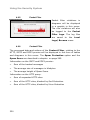
4.1.3.
Up2Date Service
The Up2Date Service makes
it easy to keep your security
system software updated: New
virus
definitions,
system
patches, and security features
will be installed to your current
system.
All Up2Date data are digitally
signed and encrypted, and are
transferred over a secure channel. Any unsigned or forged Up2Date packages are rejected and
deleted.
A number of servers are maintained for both System Up2Date and
Pattern Up2Date that are dialed in the given sequence. If the first
Up2Date server is not available, the system will automatically query
the next system or pattern Up2Dates in the list.
Important Note:
In order to download updates, the Up2Date Service makes a TCP
connection to the update server on port 443. The security system will
permit this connection without any adjustment. If there is another
security system in place upstream, you must allow the communication via the port 443 TCP to the update servers.
Note:
When using the High Availability (HA) system, please note the
special functions of System Up2Date.
48
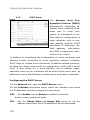
Using the Security System
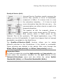
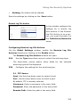
System Up2Date
The System Up2Date function allows you to import system patches
and new security features into your Internet security system. The
Up2Date packages can be downloaded either manually over an encrypted connection or automatically from the Update Server. If you
don't have an Internet connection, you can also import Up2Date
packages from a local volume.
Newly
imported
Up2Date
packages
are
presented
with
their
respective version number and file name in the Unapplied Up2Dates
table. These Up2Date packages have not been installed yet!
In order to get further information, touch the blue info button with
the cursor. If the info button is highlighted red, there will be an
automatic restart of the Security system after the installation of the
System Up2Date package.
Note:
If you are using the High Availability (HA) system, please note the
special notes for the import and installation of the System Up2Dates. The HA system is described in chapter on page 98.
49
Using the Security System
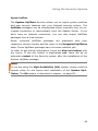
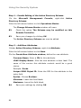
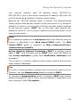
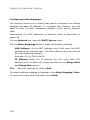
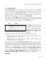
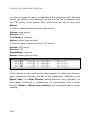
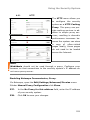
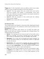
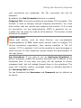
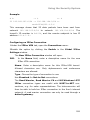
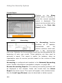
Manually downloading System Up2Dates:
1.
2.
Open the Up2Date Service menu in the System tab.
In the System Up2Date window, click the Start button
under Prefetch Up2Dates now.
The
system
will
now
check if there are any
new
updates
on
the
Update server, and will
download any updates
found.
Details
on
the
Up2Date process can be
found
in
the
Log
Window, shown in realtime (left-hand picture).
When
the
DONE
message appears, the process has completed successfully.
The Unapplied Up2Dates table lists any updates that have been
downloaded but not yet installed!
If you are using the HA system, unapplied updates will be listed in
the Unapplied Up2Dates Master window.
Automatic download of System Up2Dates:
1Open the Up2Date Service menu in the System tab.
2Click the Enable button under Prefetch Up2Dates automatically.
16.
In the selection menu Interval, specify how often the
security system should contact the Up2Date Server to check
for new System Up2Dates.
The available choices are: every hour, every day, or once per
week.
50
Using the Security System
Newly
imported
Up2Date
packages
are
presented
with
their
respective version number and file name in the Unapplied Up2Dates
table. Further information is available by clicking the Info button.
Note that the Unapplied Up2Dates in the table have not yet been
installed yet!
If you are using the HA system, unapplied updates will be listed in
the Unapplied Up2Dates Master window.
Loading System Up2Dates from a local disk:
The filename of an Up2Date update consists of the version number,
tar to signify it is an encrypted archive file, and the file extension .
gpg.
1.
Open the Up2Date Service menu in the System tab.
2.
In the System Up2Date window, click on the Browse button
next to Import from File.
17.
In the File Upload window, choose the Up2Date packages
you would like to load and click on the Open button.
Important Note:
When using Microsoft Windows, make sure not to use a UNC
Path. Instead, choose the updates by using the Look in option.
18.
In the System Up2Date window, next to Import from File,
click Start.
Successfully loaded updates will appear in the Unapplied
Up2Dates window with the version number and the file name.
Further information is available by clicking the Info button.
Note that the Unapplied Up2Dates in the table have not yet been
installed yet!
If you are using the HA system, unapplied updates will be listed
in the Unapplied Up2Dates Master window.
19.
Repeat steps 2 through 4 until all Up2Date packages have
been imported.
51
Using the Security System
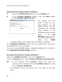
Installing System Up2Dates without the HA solution:
1.
Open the Up2Date Service menu in the System tab.
2.
In the Unapplied Up2Dates table, choose the Up2Date
updates to install.
Note:
If more than one System Up2Date file is listed in the table,
start the highest version. The smaller versions will be installed
automatically.
20.
In the Actions column, click Install.
The progress of the Up2Date installation on system 1 will be
displayed in real time in the Log Window. When the DONE
message appears, the process has completed successfully.
Installing System Up2Date with the HA solution:
1.
Open the Up2Date Service menu in the System tab.
2.
In the Unapplied Up2Dates Master
table, choose the
Up2Date updates to install.
Note:
If more than one System Up2Date file is listed, start with the
smallest version. Only one package can be installed with the
HA system.
21.
In the Actions column, click Install.
The progress of the Up2Date installation on system 1 will be
displayed in real time in the Log Window. When the DONE
message appears, the process has completed successfully.
Then the installation automatiscally starts on system 2. During
this process, the Up2Date package and the message Polled by
slave will be displayed in the Unapplied Up2Dates Slave
52
Using the Security System
table.
The table will show the message No locally stored Up2Date
packages available when the installation on system 2 has
completed successfully.
22.
If
the
Unapplied
Up2Dates
Master
table
lists
more
unapplied updates, repeat steps 2 and 3 until all updates have
been installed.
The HA system is fully updated when the Unapplied Up2Dates
Master table shows the message No locally stored Up2Date
packages available and if both systems display the same
version number.
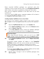
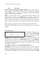
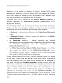
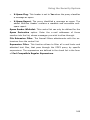
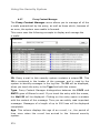
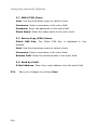
Pattern Up2Date
The Pattern Up2Date function
updates the virus patterns for
the security system’s integrated
virus scanner and the Intrusion
Protection System (IPS) with
IPS attack signatures. You can choose to update signatures manually
or automatically at certain intervals.
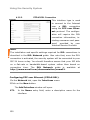
The Latest Pattern Up2Dates table shows the date of the most
recently installed Pattern Up2Date. Virus Protection Patterns and
Intrusion Protection attack signatures will be listed separately.
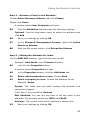
Manual Pattern Up2Date:
1.
Open the Up2Date Service menu in the System tab.
2.
In the Pattern Up2Date window, click the Start button
under Update now.
The system checks now, whether new Pattern Up2Date packages are
available on the Update Server, downloads and installs them to the
Internet security system. Details on the complete Up2Date process
53
Using the Security System
can be found in the Log Window, shown in real-time. When the
DONE message appears, the process has completed successfully.
The Installed Pattern Date will be updated when you click the
Up2Date Service under the System tab, or when you next open this
menu.
When using the High Availability (HA) solution, the virus scanner
on system 2 will be automatically synchronized with system 1.
Automatic Pattern Up2Date:
1.
Open the Up2Date Service menu in the System tab.
2.
Click the Enable button under Update automatically.
23.
In the selection menu Interval, specify how often the
security system should contact the Up2Date Server to check
for new Pattern Up2Dates.
The available choices are: every hour, every day, or once per
week.
Security Note:
Choose the hourly update option to ensure that your system is always up to date.
The automatic Pattern Up2Date is now activated. The Security system will contact the Up2Date Server at regular intervals and check
for new Pattern Up2Dates. Whenever new Pattern Up2Dates are
installed, the administrator will be sent an e-mail containing a list of
the newest virus signatures.
When using the High Availability (HA) solution, the virus scanner
on system 2 will be automatically synchronized with system 1.
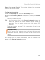
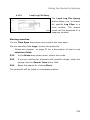
Use Upstream HTTP Proxy
54
Using the Security System
In this window you can define
the
connection
to
an
Up-
stream Proxy Server. This
function is required if you can
only connect through such an
Upstream Proxy to HTTP and
HTTPS ports.
Defining an Upstream Proxy Server:
1Open the Up2Date Service menu in the System tab.
2Click Enable next to Status to enable the function and make the
following settings:
Proxy IP Address: Enter the IP address of the Upstream Proxy
server into the entry field.
Proxy TCP Port: Enter the port number of the Upstream Proxy
server into the entry field.
24.
Save the settings by clicking Save.
25.
If an authentication is required for accessing the Upstream
Proxy Server, enable the Use Authentication function and
make the following settings:
Username: Enter a username in the entry field.
Password: Enter the password in this entry field.
26.
Save the settings by clicking Save.
4.1.4.
Backup
The Backup function allows you to save the settings of your Security
system to a file on a local disk.
This backup file allows you to install a known-good configuration on a
new or misconfigured security system. This is especially useful in case
of hardware failure, as it means replacement systems can be up and
running within minutes.
55
Using the Security System
Attention:
Version 5.0 of the security system can only load backups from
version 4.021 or higher.
Install the License Key in the Licensing menu before loading the
backup. Without the appropriate license, the system will only support
three network cards – under certain circumstances, this can lead to
WebAdmin not being reachable.
Note:
After every system change, be sure to make a backup. This will
ensure that the most current security system settings are always
available. Make sure that backups are kept securely, as the backup
contains all of the configuration options, including certificates and
keys.
After generating a backup file, you should always check it for
readability. It is also a good idea to use an external MD5 program to
generate checksums: this will allow you to check the integrity of the
backup later.
Restore a Backup
This window allows you to install the backup file of the configuration.
Loading a Backup:
1.
2.
Open the Backup menu in the System tab.
In the Restore a Backup window next to the Upload
Backup File entry field, click on the Browse button.
27.
In the File Upload window, choose the Backup file, you would
like to load and click on the Open button.
56
Using the Security System
Note:
When using Microsoft Windows, make sure not to use a UNC
Path for loading the backup. Select the Backup file with the help
of the Look in selection window.
28.
Click on the Start button.
If, during the generation of the backup file, the Encryption
function was enabled, the Enter Passphrase window will open.
29.
In the Passphrase field, enter the password.
30.
Confirm your settings by clicking Start.
The security system will now load and check the backup file. If
the ckecksums are correct, you will now receive the Backup
Information.
31.
Check the Backup Information.
32.
To import the backed-up settings into the active system, click
the Start button.
When the message Backup has been restored successfully
appears, the process has completed successfully.
57
Using the Security System
Create a Backup
This window allows you to create and archive a backup file of the
configuration of your Security system.
Manually Creating a Backup:
1.
Open the Backup menu in the System tab.
2.
In the Create a Backup window, in the Comment field,
enter a description of this backup.
When restoring system backups, this description will be displayed to help distinguish between different configurations.
Important Note:
If the Encryption function has been enabled, the backup file
will be encrypted with either the DES or 3DES algorithms, and
can only be read or loaded using the correct password.
33.
To generate the backup file, click the Start button.
The system will now generate a backup file. When the message
Backup has been created successfully appears, the process
has completed successfully.
34.
To copy the backup file to your local PC, click the Save
button.
35.
On the File download menu, choose the Save file to disk
and click the OK button.
36.
Choose a descriptive file name on the Save file as menu.
The security system will automatically produce file names,
consisting of backup, date and time:
backup_yyyymmdd_hhmmss.abf (astaro-backup-file).
37.
Check the generated backup file for readability by importing it
back into WebAdmin and clicking on the Start button.
58
Using the Security System
The security system will now load and check the backup file. If
the ckecksums are correct, you will now receive the Backup
Information.
38.
Abort the restore process by opening a different menu within
the tab.
Attention:
After each system change, create a new backup file. If you load
a new backup file and if, for example, you have changed the IP
address or forgotten the password, you might not be able to
access the newly configured system.
59
Using the Security System
Advanced
Encryption: The backup file contains all configuration settings as well
as the respective certificates and keys. The Encryption function
allows you to encrypt the file using DES or 3DES.
Encryption of e-mail Backup Files:
1.
Open the Backup menu in the System tab.
2.
Scroll to the Advanced window.
39.
Enable the Encryption function by clicking on the Enable
button.
The Encryption function is enabled, when the status light shows
green.
40.
In the Passphrase entry field, enter the password.
Security Note:
With passwords with up to seven characters, the Backup
file will be encrypted with DES and from eight characters
on with 3DES.
41.
To confirm, enter the password again into the Confirmation
entry field.
42.
Click the Save button to save these settings.
All Backup files that have been created manually or automatically by
the system, will now be encrypted with the defined password.
Important Note:
A backup file that has been encrypted with Encryption can only be
loaded to the system with the password that was used for the
creation of the Backup.
Send Backups by E-Mail: The Security system can also send you
automatically created backup files by e-mail, so that you don’t have
60
Using the Security System
to remember to save the settings of your Internet security system
manually on a data carrier. Then the file is e-mailed to the entered email address. These e-mailed files are about 100 kilobytes long.
Generating an E-Mail Backup File:
a.
b.
Open the Backup menu in the System tab.
In the Advanced window enable the Send Backups
by E-Mail function by clicking on the Enable button.
The Backups by E-Mails function is enabled, if the status light
shows green.
Important Note:
If the Encryption function has been enabled, the backup file
will be encrypted with either the DES or 3DES algorithms, and
can only be read or loaded using the correct password.
43.
Use the Interval drop-down menu to define how often
backups should be made.
The available choices are: Daily, weekly, and monthly.
44.
In the E-Mail to field, enter the e-mail addresses, which
should receive the backup files in regular intervals.
45.
Click the Add button next to the E-Mail to entry field, to add
this address to the ordered list.
If you would like to add more addresses, repeat step 5.
46.
If you wish to generate and send a backup file immediately,
click the Start button next to Send backup now.
47.
Check the generated files for readability by importing the
respective backup file and clicking on the Start button.
The security system will now load and check the backup file. If
the ckecksums are correct, you will now receive the Backup
Information.
61
Using the Security System
48.
Abort the restore process by opening a different menu within
the tab.
Editing E-Mail Addresses:
Please see chapter
on page 34 for a description of how to use the
ordered list.
4.1.5.
SNMP
The
Simple
Management
Network
Protocol
(SNMP) monitors and manages
the local network. SNMP allows
the administrator to make quick
queries about the condition of the network devices, such as the
number and configuration of the network interfaces, the forwarded
traffic, the current processes and hard disk utilization. Next to the
current state, tendencies and time rows are interesting. They give a
detailed insight into the functions of a network – the history can be
monitored and remedied before turning into a real problem.
Configure the access rights to the SNMP service in the SNMP Access
window. The users of the configured networks can then conduct
queries about the SNMP server on the security system with their read
only rights.
Security Note:
The SNMP data traffic (Protocol version 2) between the Security
system and the network is not encrypted.
Authorizing Access to the SNMP Server:
1.
62
Enable SNMP Access by clicking the Enable button.
Using the Security System
2.
From the Allowed Networks selection field, select the
networks that you wish to allow for accessing the SNMP
server.
49.
Enter the Community String in this entry field.
50.
Save your configuration by clicking Save.
In
the
SNMP
Traps
window you can define a
Trap-Server,
to
which
relevant information for
the system administration is sent as SNMP Traps. To recognize those
Traps a special SNMP monitoring software is required.
The messages, which are sent as SNMP Trap, contain the Object ID
(OID). The OID for messaging events (1500), the classification of the
message (DEBUG = 0, INFO = 1, WARN = 2, CRIT = 3) and the
relevant error code (000 bis 999) are attached.
Example: The notification INFO-354: Intrusion Protection Pattern
Up2Date
succeeded Intrusion Protection Pattern Up2Date
succeeded has in this case the OID 1.3.6.1.4.1. and is assigned the
following string: [<HOST>][INFO][354]. For the wildcard <HOST> the
hostname of the security system will be displayed.
Assigning the Trap Server:
1Enable SNMP Traps function by clicking the Enable button.
The status light will show green and an advanced entry window
will open.
51.
In the SNMP Tap Assignment table, click the New Assignment button.
52.
Click on the new line in the Host IP Address column.
An editing window will open.
63
Using the Security System
53.
Enter the IP address into the entry field of the server and
save your entry by clicking on the Save button.
54.
Click on the entry public in the Community String column
and enter the Community String into the entry field.
The new assignment will be accepted immediately.
4.1.6.
Remote Syslog Server
This function allows you
to forward log messages
from the Security system
to other hosts. This is
especially useful for networks using a log host to
collect logging information from a number of different hosts. By
default, this function is disabled. A Logging Daemon, compatible with
Syslog protocol must be running on the selected host.
Attention:
In the System/Remote Syslog Server menu, do not select one of
the security system’s interfaces (such as eth0) as the destination
address (host).
Host: Enter the host, which should receive logging information in the
drop-down menu. When a host has been selected, log forwarding is
enabled immediately: no further messages are displayed.
In order to select a logging host (i.e., a network with netmask
255.255.255.255) you will first have to define it in the Definitions/Networks menu. The definition of networks is covered in
greater detail in chapter
on page 105.
Service: The Syslog protocol is set by default. You can also use this
drop-down menu to configure the service ( port) that should be used
on the remote server.
64
Using the Security System
Logs: This selection field allows you to select log files that should be
delivered to the remote host.
65
Using the Security System
4.1.7.
User Authentication
The security system supports User Authentication using the
SOCKSv5, SMTP, and HTTP proxy services and can control which
users are allowed to use which services. User accounts can be defined
on the security system, through the Definitions/Users menu. Or on
an external user database. Supported external databases include
RADIUS, SAM (Windows NT/Windows 2000/XP-Server), Microsoft
Active
Directory, the
domain
joining
method
of
NTLM
and
OpenLDAP. If an external user database is already present on the
network, you can use it instead of having to re-enter user accounts on
the security system itself.
Important Note:
Please note, that several authentication methods cannot be supported at the same time.
In MS Windows based networks the Domain Controller (DC) manages access to a set of network resources (e.g., applications, printers,
etc.) for a group of clients. The user needs only to log in to the
domain to gain access to the resources. A Domain Controller is a
server that is running a version of the MS Windows 2000 Server or
2003 Server operating system and has Active Directory (AD)
installed, which is Microsoft’s trademarked directory service.
A directory service provides a centralized location to store information
in a distributed environment about network devices, services, and the
people who use them. For MS Windows users it provides account
information, privileges, profiles, and policy. When an authentication
method is used together with Active Directory and with the corresponding settings, the authentication, e. g. before accessing an own
Service is no longer made by the security system but by the ActiveDirectory-Server.
User Authentication requires users to identify themselves before using
network services. In comparison with an IP-based access control the
66
Using the Security System
user-based access control allows for user-based Accounting in the
HTTP-Proxy access protocol.
Proxy Service and Authentication Methods
The SOCKSv5, SMTP, and HTTP services can be configured to allow
or disallow clients based on IP address or on username and password
combinations. In order to use User Authentication, you must select
at least one database against which the security system should
authenticate users. If user authentication is enabled and no database
is selected, the proxy service cannot be used.
The security system supports user authentication against ...
•
a RADIUS Server
•
an NT SAM user list
•
an Active Directory/NT Domain Membership
•
an LDAP Server
•
an internal database defined in WebAdmin
The five user databases can be checked one after the other.
4.1.7.1.
RADIUS
RADIUS stands for Remote Authentication Dial In User Service
and is a protocol for allowing network devices (e.g., routers) to
authenticate users against a central database. In addition to user
information, RADIUS can store technical information used by network
devices. Such as protocols supported, IP addresses, telephone
numbers, routing information, and so on. Together this information
constitutes a user profile that is stored in a file or database on the
RADIUS server.
In addition to authenticating dial-up users, RADIUS can be used as a
generic authentication protocol.
The RADIUS protocol is very flexible, and servers are available for
most operating systems, including Microsoft Windows NT/2000. The
67
Using the Security System
RADIUS implementation on this security system allows you to configure access rights on the basis of proxies and users.
Before you can use RADIUS authentication, you must have a
functioning RADIUS server on the network. As passwords are transferred in clear text (unencrypted), we strongly recommend that the
RADIUS server be inside the network protected by the security
system, and that the security system and server be on the same
switch.
The following section details the setting up Microsoft IAS (RADIUS
Server for MS Windows NT and 2000). If you use a different server,
you will need the following information to enable the operation of the
security system together with the user authentication.
The authentication request comprises three set fields:
•
Username
•
Password in clear text (PAP)
•
Type of proxy (the string http, smtp or socks) in the NASIdentifier field
Your RADIUS server should use this information to determine whether
or not access should be granted, and should send back a properly
formatted reply.
Configuring Microsoft’s IAS RADIUS Server:
IAS is a part of all versions of Microsoft Windows 2000 Server, but is
generally not installed by default. For Microsoft Windows NT4, IAS is
a part of the NT4 Option Pack and is available without charge. The
MS Windows NT4 IAS has fewer features than the 2000 version, but is
nevertheless sufficient for user authentication with the security
system.
1.
Check that the IAS service is installed. If it is not, install it
now.
2.
68
Create a user group for every proxy to be used.
Using the Security System
Tip:
Name the group according to the proxy to be used. For
example, name the group for the HTTP Proxy HTTP Proxy
Users.
55.
For each group, add the users who should be allowed to use
this proxy service.
56.
Make sure that the user flag Allow dial-in access to the
network is set for every user in these groups.
You can find this setting in the user properties dialog box. MS
Windows NT/2000 needs this flag to answer RADIUS inquiries.
57.
Open the administration program for the IAS service.
58.
Add a client. This requires the following information.
Client Name: Enter the DNS name of your security system
here.
Protocol: Choose RADIUS.
IP Address of the Client: Enter the internal IP address of the
security system.
Client Vendor: Choose RADIUS Standard.
Shared Secret: Enter a password here. You will need this password again when configuring the RADIUS server with WebAdmin.
Security Note:
For the Shared Secret only passwords consisting of
alphanumeric, minus (-), and period (.) characters are
allowed. Other characters, for example %!#_{} are not
allowed.
59.
Now open the RAS rules menu.
A standard rule is listed here. If you intend to use IAS only
with the security system, you can delete this entry.
69
Using the Security System
For every proxy, enter a rule. Choose a descriptive name, such
as HTTP access.
Add two conditions:
1. Condition 1: The NAS Identifier field must correspond to a
string from the following table.
Proxy Type
NAS Identifier String
HTTP
http
L2TP over IPSec
l2tp
PPTP
pptp
SOCKS
socks
SMTP
smtp
WebAdmin Access
webadmin
Surf Protection
“Profilname”
2. Condition: The Windows group of the user must match the
group established in step 2.
Access is granted only when both conditions are met.
60.
Edit the profile so that only an encrypted connection is
allowed by disabling the No Encryption function in the
Encryption register.
61.
Edit the profile so that an unencrypted authentication is
allowed by disabling the Encrypted Authentication (PAP)
function in the Authentication register.
Leave the other values unchanged.
62.
Open the WebAdmin configuration tool and open the User
Authentication menu in the System tab.
63.
In the RADIUS Server Settings window, click the Enable
button next to Status (the status light will show green).
70
Using the Security System
Address
or
Hostname: Enter the
IP address or the host
name of the RADIUS
server.
Shared Secret: Enter the Shared Secret from step 6.
64.
65.
Click the Save button to save these settings.
In the Proxies tab, open the menu corresponding to the
proxy service you wish to use.
66.
If User Authentication is not enabled (red status light), click
the Enable button.
Authentication Methods: Choose RADIUS from the selection
field.
67.
Now confirm your settings by clicking on the Add button.
The user authentication using RADIUS is now active.
The IAS service will log every access attempt in the Microsoft
Windows NT/2000 Event Log.
In order to prevent the Windows Event Log from overflowing, the
security system stores RADIUS access information for five minutes.
This may mean that changes in the RADIUS database will not be
reflected at the security system for a few minutes.
Attention:
The security system sends queries on UDP port 1812.
71
Using the Security System
4.1.7.2.
SAM – NT/2000/XP
This authentication method uses an MS Windows NT/2000 Domain
Controller or standalone server. Many businesses already use MS
Windows NT/2000 networks based on ActiveDirectory.
The advantage of SAM is that it is very easy to configure if the
network already has a Primary Domain Controller (PDC) or if a
server with a user database is running.
The drawback, however, is that this system does not distinguish
between different user groups. You can either allow all users in an
SAM database access to a proxy or none of them.
Configuring SAM – NT/2000/XP:
In order to use this authentication method, you will need to
have a Microsoft Windows NT or
2000 server on your network
that contains the user information. This can be either a
Primary Domain Controller (PDC) or a standalone server.
Note that Windows servers have a NetBIOS name (the NT/2000
server name) as well as an IP address.
1In the System tab, open the User Authentication menu.
68.
In the SAM (NT/2000/XP) Server Settings window, click
the Enable button next to Status.
PDC Name: Enter the name of the Domain Controller in this
entry field.
Since, beginning with Windows 2000, these names are also
official DNS names, only names consisting of alphanumeric,
minus (-), and period (.) characters are allowed.
Other characters, for example %!#_{} are not allowed.
PDC Address: Enter the IP address of the Domain Controller.
72
Using the Security System
BDC Name: If you have a Backup Domain Controller, enter its
name in this entry field. If you do not use a BDC, enter the name
of the PDC here.
BDC Address: If you have a Backup Domain Controller, enter its
IP address here. If you do not use a BDC, enter the IP address of
the PDC here.
NT4 Domain: Enter the name of your MS Windows NT/2000Domain.
Allowed characters are: Letters of the alphabet, hyphen (-), and
underscore characters (_).
Note:
This is not the Internet domain, as in Company.com, but rather
a simple designator, e.g., Intranet. If you are using a standalone server rather than a Domain Controller, enter its NETBIOS
name here. This corresponds to the PDC Name entry.
69.
Confirm your settings by clicking Save.
Security Note:
For the Shared Secret only passwords consisting of
alphanumeric, minus (-), and period (.) characters are
allowed. Other characters, for example %!#_{} are not
allowed.
Security Note:
If you use SAM authentication, make sure to disable the Guest
account on your Windows domain. Otherwise all username/
password combinations will be accepted as valid.
73
Using the Security System
4.1.7.3.
Active Directory/NT Domain Membership
In this authentication method the NTLM protocol is used. NTLM
stands for New Technology LAN Manager and is a further development of the LAN manager protocol LM for the user authentication in
Windows networks. The Challenge Response based NTLM protocol is
by default contained in the MS Windows 2000, XP and 2003 Server
operating systems. The Squid Proxy can authenticate users through
this protocol.
With this authentication method a MS Windows NT/2000 Domain
Controller (DC) is used for the evaluation of requests. For further
information on Domain Controller (DC) please, refer to the introduction of the User Authentication menu on page 66.
The authentication method with NTML next to RADIUS also supports
remote authentications. The method with NTLM in comparison to
RADIUS offers the advantage that, due to the Single-Sign-Onmechanism, the user needn’t always log in to the Internet with his
User Name and Password.
The
functioning
of
the
domain-connection-method
of
NTML
is
completely different from the three other authentication methods on
this security system. In MS Windows environments, the authentication with NTML is in general configured for clients, using the Internet
Explorer browser. However, also systems with clients that use the
browsers Firefox or Mozilla (e.g. Mozilla 1.6) can be successfully
operated.
Note:
In order for the domain joining process to work, one of the Domain
Controllers (DC) for this domain must be in the systems broadcast
range. The authentication with NTLM can at present only be used for
the HTTP proxy to perform Single-Sign-On for Internet Explorer
clients!
The notion of Single Sign-On (SSO) is in general used for a unique,
central sign-on of a user into an IT structure. This is very useful since
74
Using the Security System
the user must enter his identification data only once and will then be
authenticated for all centrally connected services. This allows for the
implementation of a uniform user and rights structure in a company.
In the conception of a central and unique authentication that shall be
based on existing infrastructures a series of requirements must be
met:
•
Central administration: user authentication data must be maintained on only single place only
•
Simple use from the perspective of the user: data shall be
consistent and not kept twice, i.e. only one password for all
services
•
Security: passwords shall not be readable for attackers
The advantage of the latter is that the data in the concept presented
here are never transferred over networks without encryption and are
subjected to a specific expiration period. This makes a Brute-Force
attack against encrypted data almost impossible.
Configuring Active Directory/NT Domain Membership:
1In the System tab, open the User Authentication menu.
70.
In the Active Directory/NT Domain Membership (NT/
2000/XP) Server Settings window, click the Enable button
next to Status.
Enabling
the
NTLM
Domain
Membership in the
Status line does not
unregister
the
security system from
the
domain.
This
must be done on the domain controller.
Domain Member Status: Shows Joined domain „DomainName“ when join was successful.
75
Using the Security System
Domain: Enter the name of your MS Windows NT/2000-Domain.
Allowed characters are: Letters of the alphabet, hyphen (-), and
underscore characters (_).
Note:
This is not the Internet domain, as in Company.com, but rather
a simple designator, e.g., Intranet.
NetBIOS Hostname: Enter the NetBIOS hostname the security
system should have in the domain. You can just invent a name.
It does not have any additional significance. However, to avoid
inconsistencies, please choose a name that is not already used in
your domain.
Attention:
Please make sure not to use hostnames that are used by other
systems and especially not the hostname of the domain controller – it could demote the Domain Controller to a Member
Server!
Account: Enter the account name that is allowed to join
computers to a domain. Usually it is the Administrator. This
name is only used for joining the domain and is not saved on the
security system!
Password: Enter the password for the above account. This
password is only used for joining the domain and is not saved on
the security system!
71.
Confirm your settings by clicking Save.
Once, the security system is successfully joined to the Domain, the
confirmation will be displayed under Domain Member Status.
4.1.7.4.
LDAP Server
LDAP, the Lightweight Directory Access Protocol defines the way
in
76
which
clients
communicate
with
X.500-conforming
directory
Using the Security System
services. The protocol thus specifies the type of access to such a
directory service.
The security system uses the LDAP protocol to authenticate users for
several of its services. The security system allows or denies access on
the basis of certain attributes or group memberships established on
the LDAP server.
This system supports the Microsoft Active Directory and Novell
eDirectory LDAP servers as well as those based on the Open Source
OpenLDAP software.
Microsoft Active Directory is an indexing service designed especially for Windows NT/2000 networks, and allows the central management and organization of network resources. It allows users to access
system resources after a single sign on to a central server, and offers
administrators centrally organized management of users, regardless
of network topology or protocols used.
In order to use this directory service, you will need an MS Windows
NT/2000 Domain Controller.
Novell eDirectory – Novell Directory Service 8 - is an X.500-based
index service designed to manage users, access rights, and other
network resources. eDirectory is available for Netware versions 5 and
higher, MS Windows NT/2000, Linux, and Solaris.
The OpenLDAP Foundation, the group which manages the OpenLDAP open source project, has released the Stand-Alone LDAP
server, called SLAPD. OpenLDAP can also be used to build a
networked directory service with various other LDAP servers: For
instance, the iPlanet Directory Server from Sun Microsystems is
based on OpenLDAP code and fully compatible.
77
Using the Security System
User Authentication
LDAP uses the Distinguished Name (DN) of a user to identify him
or her. This name must be unique within the directory.
Microsoft Active Directory (AD) and Novell eDirectory (NDS8)
give every object a defined DN. This DN identifies the object uniquely
in the AD index or NDS tree. This DN is composed of the Common
Name (CN) and Domain Component (DC).
Example: CN=Administrator, CN=Users, DC=example, DC=com
MS Active Directory also allows for user authentication by User
Principal Name (UPN). This name consists of the login name and
DNS name of the domain.
Example: [email protected]
OpenLDAP simply uses the Common Name (CN) to identify users.
Please make certain that every user has a unique CN.
Security Note:
User authentication with a stand-alone LDAP server involves
sending passwords in clear text over the network. As these
passwords are not encrypted, an attacker with access to the
network may be able to intercept them.
Note:
User authentication with an LDAP Server requires that the DNS
Proxy on the Proxies/DNS menu be enabled.
78
Using the Security System
Configuring the Microsoft Active Directory Server:
Make sure that there is a user configured on your LDAP server to have
full read privileges for the directory. This will be the query user.
Security Note:
Make sure that the user has only read privileges.
Microsoft Active Directory (AD) can grant privileges on the basis
of group memberships, or on the basis of particular user attributes. In
most cases, it is easier to use the Member Of query type to
authenticate by group.
The Directory can be extended by self-defined attributes. If you wish
to authenticate on the basis of particular User Attributes, every user
account in the directory must be edited to define access rights. This is
done by setting a particular attribute for each user which either
grants or denies access to a service.
The
following
example
illus-
trates the configuration for a
hypothetical
small
company
example.com:
The user John Smith is in the
Trainees directory.
DN: cn=john smith,
ou=trainees, dc=example,
dc=com.
LogonName:
[email protected]
This user can use his LogonName and password to log on to services
like the SOCKS Proxy. The security system checks the user’s DN and
password.
If
there
is
only
one
DN
that
corresponds
to
[email protected], and if the supplied password is valid, the user
will be allowed to use the SOCKS proxy.
79
Using the Security System
If you wish to use Group Membership to control access rights,
complete the following steps to configure the Microsoft Active
Directory:
Step 1 – Creating a Security Group:
a.
In the Microsoft Management Console, click the
domain with the right mouse button.
Example: Domain example.com
72.
With the left mouse button, click New and then Group.
A new window will open labeled New Object - Group.
73.
Enter a unique name for the group in the Group name field.
Example: socks_users for the SOCKS Proxy
74.
Under Group type select Security.
75.
Save your settings by clicking OK.
You
have
now
created
a
new
socks_users.
Step 2 – Adding Users to the Group:
80
Security
Group
named
Using the Security System
ħ
Ā
İ ĀĀ
Ā
Ā
Ā
Āǿ
Ā
Āȑ Ā
Ā
Ƌ ƒ ĀĀ Ɣ Ā
Ā
Ā
Ā
Ā
ӄ Ā
Ā
Ѯ Ā
ĀنĀ
rĀ Ā
ö
ǜ
̧ Ā
쏿
甀
Ā
圀
洀
甀
堀
༄
༄༄퀀
༄༄쑲
༄༄岐
Ā
· Ā
Ā
Ā
Ā
ŠĀĀ
Ā
쐀
Ā
圀
༄༄퀀
༄
첌쁊뙈
༄
阥
༄ Ḁ
༄
가 嚄
阥
༄ Ḁ
༄༄
밀 沄
␀
༄༄岐
༄
༄
༄༄먀
༄༄岐
༄
༄༄刀
劚
༄༄༄༄堀
瘟
绸
窖
癔
둣
༄༄堀
髮
༄༄岐
༄༄༄༄搼
簌 ﻢ풷
༄༄
穚
驟
༄༄堀
༄༄퀀
༄
༄
༄༄岐
༄༄퀀
乫
༄
༄
༄
༄༄༄༄堀
犿
༄
桤
༄༄桤塤
༄
ﻞ稕
༄ 娀ༀ ༄ ༄ ༄༄堀
가
༄༄
༄
༄
༄
༄
༄༄༄༄堀
༄
阥
༄
풾 壋精퓉
༄ ༄ ༄
༄
༄
Ḁ
༄
༄༄岐
Ā
༄
༄
༄༄퀀
༄
岐
Ā
Ā
ǿ
─
圀
내
阥
༄༄蠀
༄
༄༄岐
༄
鰀롪
洀
쏿 ༄༄ Ḁ
༄
༄
牺
甀
洀
༄༄堀
༄
༄༄
ĀŲ
鳾Ā ӳ Ā
Ā
Ā״Ā
Ā¸ Ā
Ā ǿ
Ā
༄
퀀
堀
Ā
Ж
Й
ﴀҼ ҰĀ
Ā ǿ
ӫ
༄༄༄퀀
쑲
༄
嘢
ǁ Ā
Ā
Ā; Ā
Ā
ĀתĀ
Āǿ
Ā
༄
༄ ༄ 퀀⋣
9
ʈ̣Ą Ą
一
Ā
Ā
Āǿ
Ā
一
圀
җ Ā
ǿ
圀
圀
༄
堀
Ā
ĀĀ
Ā
ϭ ĀĀ ЈĀ ĀĀ
ĀĎ
Պ
Ā
Ā
Ā Ā ĀגĀĀ
Āǿ
Ā Ā
å
Ā鋾
ĵ Ā
Ā
Āǿ
ֶĀ
Ā
ǿĀ
ȄĀ ȉ Ā
Āǿ
Ā ϑ
ն
Ā
ʤ ʼ ĀĀ Ā ˖ Ā Ā
Ā Ā
Ā
Ā∀
Āǿ
Ā
Ā
Ā
ĀĀĀ
⌀
Ā ─Ѣ Ā ђ ҁĀ Ā
Ā؛Ā
Ā
Ā
Ā Ā
Ϋ ĀĀ Ā ΰ
ư
Ā ȁ Ā
Ā
ĀĀ
Ā Ā
ǿ
Ñ
ǵ
ʆʥ Ā
Ā
ĀĀ
ĀƘ Ā
Āἀ
Ā
Ā
Ѐ
Ā
一
Ā
Ν
Ε
ĀĀ
¡ Ā
藿
Ā
̉
ĀƖ Ā
Ā
ɞ
Ā
Ƌƒ Ā 1 Ā ħ ĀĀ İ Ā Ā ŏ
Ā
Āǿ
Āȗ Ā
ﰀ
Ā
Ā
Ɗ Ā
Ā
ǿ
Ā
Ā
ŏ
༄༄퀀
༄༄蠀
༄༄
༄༄堀
༄༄
81
Using the Security System
Example: John Smith in the Trainees directory.
76.
Left click the Properties button.
A window named Properties will open.
77.
In the Properties window, select Member Of tab.
78.
Click Add to add the new group.
The Select Groups window will open.
79.
Now choose the Security Group you wish to add the user to.
Example: socks_users
80.
Save your changes by clicking OK.
The new Security Group will be added in the Member Of
window.
81.
Save your settings by clicking OK.
Now execute the settings on the Internet security system. The
settings in the configuration tool WebAdmin are explained on page
88.
Microsoft Active Directory, self defined attributes:
User authentication with Microsoft Active Directory can also use user
attributes to assign access rights. For large organizations, however,
this can be time-consuming to configure.
82
Using the Security System
Note:
According to the LDAP standard, each user attribute must have an
associated object ID, or OID. Object ID numbers are designed to
be unique across the entire Internet; in order to manage this, the
Internet Assigned Numbers Authority (IANA) has been charged
with assigning OID prefixes to organizations.
If your organization does not yet have an official OID space, you can
request an OID prefix from the IANA at www.iana.org. Once you
have an OID space, you should consider how best to use it to
describe your network structure. Remember that each user attribute
will require a unique OID.
In order to configure user attributes, the Microsoft Management
Console must be used to modify the Active Directory Schema. In
order to do this, you must first mark the schema as editable.
83
Using the Security System
Step 1 – Enable Editing of the Active Directory Schema:
1In
the
Microsoft
Management
Console,
right-click
Active
Directory Schema.
2Use the left mouse button to click Operations Master.
The Change Schema Master window will open.
82.
Check the option The Schema may be modified on this
Domain Controller.
83.
Save your changes by clicking OK.
The Active Directory Schema can now be edited.
Step 2 – Add New Attributes:
1Under Active Directory Schema, right click Attribute.
2Use the left mouse button to click New.
3In the Create New Attribute window, define the new attribute.
Common Name: Enter a CN for this attribute.
LDAP Display Name: Give the new attribute a clear label. The
name of the service this attribute controls would be a good
choice.
Example: Socks.
Unique X500 Object ID: Enter the OID for this attribute in the
entry field.
Syntax: Choose Boolean.
Minimum: Leave this field blank.
Maximum: Leave this field blank.
84.
84
Save your settings by clicking OK.
Using the Security System
Step 3 – Allocate a Class for the Attribute:
1Under Active Directory Schema, left-click Classes.
2Right-click Users.
A window named User Properties will open.
85.
Click the Attributes tab and make the following settings.
Optional: Use the drop-down menu to select the attribute and
click Add.
86.
Save your settings by clicking OK.
87.
In the Microsoft Management Console, right-click Active
Directory Schema.
88.
With the left mouse button, click Reload the Schema.
Step 4 – Setting the Attribute for Users:
1In the ADSI Edit window, right-click the user to edit.
Example: John Smith in the Trainees directory.
89.
Left click the Properties button.
A window named Properties will open.
90.
In the Properties window, click the Attributes tab.
91.
Select which properties to view: Choose Both.
92.
Select a property to view: Choose the attribute to set.
Example: Socks.
Syntax: This value was set while creating the attribute and
cannot be changed.
From step 2, this should be. Boolean.
Edit Attribute: You can use this field to set the value of the
attribute. The possible values are TRUE and FALSE.
Value(s): The current value of the attribute is shown here.
93.
Save your settings by clicking OK.
85
Using the Security System
Now make the settings on the Internet security system. The settings
in the configuration tool WebAdmin are explained on page 88.
Configuring a Novell eDirectory Server:
Make sure that there is a user configured on your LDAP server to have
full read privileges for the directory. This will be the query user.
Security Note:
Make sure that the user has only read privileges.
In most cases, you should use the groupMembership query type
with Novell eDirectory (NDS8), as this allows an existing user
index to be easily extended for proxy rights.
The index can also be configured to use user-defined attributes, which
must be manually set for each user in the index. If you wish to authenticate on the basis of particular User Attributes, every user
account in the directory must be edited to define access rights. This is
done by setting a particular attribute for each user which either
grants or denies access to a service.
You will need Novell ConsoleOne to configure the eDirectory Server.
The configuration and management of the Novell eDirectory server is
described in detail in the accompanying documentation. You can find
these documents at:
http://www.novell.com/documentation/lg/edir87/index.html
Then make the settings for the Internet security system. The settings
in the configuration tool WebAdmin are explained on page 88.
86
Using the Security System
Configuring the OpenLDAP Server:
Make sure that there is a user configured on your LDAP server to have
full read privileges for the directory. This will be the query user.
Security Note:
Make sure that the user has only read privileges.
With OpenLDAP, users are identified on the basis of their Common
Names (CN). Please make certain that every user has a unique CN.
Important Note:
With the installation of the software alle existing data will be deleted
from the computer!
Because there are many different LDAP servers based on the
OpenLDAP code, it is impossible to describe them all here. For
further information, please consult the documentation accompanying
your LDAP server.
If you are using the SLAPD server from the OpenLDAP Foundation,
the current documentation is available at:
http//www.openldap.org.
Configuring LDAP on your Security System:
Make sure that there is a
user configured on your
LDAP server to have full
read
privileges
for
the
directory. This will be the
query user.
You will need the Distinguished Name (DN) of
this user as well as the IP
address of your LDAP server in order to complete the configuration of
the security system.
87
Using the Security System
Security Note:
Make sure that the user has only read privileges.
1.
In the System tab, open the User Authentication menu.
2.
In the LDAP Server Settings window, enable the system by
clicking Enable next to Status.
LDAP Type: Choose the type of LDAP server to use.
The available choices are: Microsoft Active Directory, Novell
eDirectory and OpenLDAP.
Unique User Attribute: This attribute defines how users should
be authenticated on the LDAP server. The attributes available
here depend on the type of LDAP server you are configuring. If
you wish to use a self-defined attribute for authentication, select
Selfdefined here.
With the Microsoft Active Directory server, you can also
choose to authenticate by User Principle Name (UPN) or
saMAccountName.
The
Novell
eDirectory
and
OpenLDAP
servers
allow
authentication by the Common Name (CN), Surname (SN),
and Unique Identifier (UID) attributes.
Attribute
Name:
This entry field is only
shown
if
selected
thenticate
you
to
by
have
aua
Selfdefined attribute from the Unique User Attribute dropdown menu.
Enter the attribute to use for authentication here.
IP Address: Enter the IP address of the LDAP server.
TCP Port: Enter the TCP port of the LDAP service. By default,
this is set to 389 (the standard port for LDAP).
88
Using the Security System
Bind DN: The value to enter here depends on the type of LDAP
server you are using.
1. Microsoft Active Directory
Microsoft Active Directory can use either the User Principal
Name (UPN) or the full Distinguished Name (DN) of the
user.
Examples:
UPN: [email protected]
DN: cn=administrator, cn=users, dc=example, dc=com
2. Novell eDirectory
Enter the full Distinguished Name (DN) of the user.
Example:
DN: cn=administrator, o=our_organisation
3. OpenLDAP
OpenLDAP and OpenLDAP-conforming servers can only use the
Distinguished Name (DN) of users.
Base DN: Enter the object name to be used as the basis for all
client actions.
Examples:
For MS Active Directory: dc=example, dc=com
For Novel eDirectory: o=our_organisation
89
Using the Security System
94.
Enter the password in the Password entry field. This
password should also be used for the Administration of the
Stand-alone-LDAP-Server.
Security Note:
Use a secure password! Your name spelled backwards is,
for example, not a secure password – while something like
xfT35$4 would be.
95.
Click the Save button to save these settings.
Security Note:
As long as the LDAP authentication by attribute
function is disabled, all users who are listed in the directory
with a unique DN and a valid password can use the HTTP,
SMTP and SOCKS proxies, and can also access the
WebAdmin tool.
Advanced Authentication with LDAP:
1Enable the LDAP authentication by attribute function by clicking
Enable next to Status.
2Use the Service drop-down menu to select a service.
The available services are: HTTP, SMTP, SOCKS and WebAdmin.
96.
In the Attribute Name field, enter the name of the attribute.
If you are using authentication using the MemberOf property on
a Microsoft Active Directory Server, this should be the name
of the Security Group to use.
Example: socks_users.
90
Using the Security System
97.
In the Attribute Value field, enter the DN for the attribute.
The attribute value is the DN.
Microsoft
Active
Directory displays the
DN of attributes in the
Management Console,
under ADSI Edit:
Here, under the Base
DN
(example:
dc=example, dc= com),
find the attribute name
(example: socks _users)
and
right-click
it.
A
window labeled CN=socks_users Properties will open.
Use the Select which properties to view drop-down menu to
choose Both, and in the Select a property to view drop-down
menu, choose distinguishedName. The DN for this attribute
will be shown in Value(s).
98.
Click the Save button to save these settings.
Every
member
defined
as
a
MemberOf
the
security
group
socks_users will be allowed to use this service.
91
Using the Security System
4.1.8.
WebAdmin Settings
Configure the access to the WebAdmin configuration tool in this
menu.
General Settings
Language: In this dropdown menu you can determine the language.
Timeout (seconds): In this entry field enter the intervals in seconds, in which WebAdmin automatically logs you out, if there are no
actions. By default, the system is set to 300 seconds after the installation. The smallest possible interval amounts to 60 seconds.
Click the Save button to save these settings.
If you close your browser with an open WebAdmin session without
closing WebAdmin through Exit, the last session remains active until
the end of the time-out.
TCP Port: If you want to use the standard port 443 for the HTTPS
service for another purpose (such as a deviation with DNAT), you
must enter another TCP Port for the WebAdmin Interface here.
Possible values are 1024-65535, while certain ports are reserved for
other services. In order to address WebAdmin after a modification,
you must separately link the port through a colon to the IP address of
the Internet security system,
e.g.: https://192.168.0.1 :1443.
92
Using the Security System
Access and Authentication
Allowed Networks: Add
those networks to the selection field that are authorised to access WebAdmin. As with SSH, Any
is
entered
here
for
a
smooth installation. In this
case and if the password is available, WebAdmin can be accessed
from everywhere.
Security Note:
As soon as you can limit the access to the Internet security
administration (for example your IP address in the local network), replace the Any entry in the Allowed Networks selection field
through a smaller network.
The safest solution is, if only one administrator PC has access to the
Internet security system through HTTPS.
Networks can be defined in the Definitions/Networks menu.
Authentication Methods: Select the authentication method in the
selection field. In order to give you access to the Internet security
system
through
the
configurations
tool
WebAdmin
after
the
installation, the authentication method Local Users has already been
defined here and the respective User hase been entered in the
Allowed Users selection menu.
Further available authentication methods are NT/2000/XP Server,
RADIUS Database and LDAP Server.
Local Users are administered in the Definitions/Users menu.
Allowed Users: By default this is set to the user admin.
Local users are defined in the Definitions/ Users menu.
Log Access Network Traffic: All connections to the WebAdmin
configuration tool are logged to the Packet Filter Logs as Accept
93
Using the Security System
rule. The Packet Filter Logs can be found in the Local Logs/
Browse menu. By default, this function is disabled.
Enable this function by clicking on the Enable button (status light on
green).
Block Password Guessing
This function can be used
to limit the number of attempts to log in to the
WebAdmin
configuration
tool. After a specific number of attempts, the access from this IP address will be denied for a
given time span.
Configuring the Blocking Protection for Login Attempts:
1In the System tab, open the WebAdmin Settings menu.
2Make the following settings:
After failed Attempts: Select the maximum allowable number
of attempts in the drop-down menu.
Block IP for Period: Enter the time span for the blocking
protection in the entry field.
99.
Save your changes by clicking Save.
Now, the blocking protection is enabled. The Never block Networks
window, allows you to exclude networks or hosts from the blocking
protection.
94
Using the Security System
4.1.9.
WebAdmin Site Certificate
Encryption systems are an important part of many modern security
systems. They are used, for example, when transmitting confidential
information over Virtual Private Networks (in chapter
on page
280), in User Authentication and Up2Date Service or, to securely
administer the security system over the network.
Certificates and Certificate Authorities (CA) are an essential part of
modern cryptographic protocols, and help close the gaps left open by
other systems. Public Key Algorithms offer a particularly elegant
form of encryption. They do, however, presuppose that the public
keys of all communications partners are known.
At this point, a third, trusted party is used to ensure the validity of
public keys. The third party issues certificates guaranteeing the
authenticity of these keys: this third party is called a Certificate
Authority (CA). A certificate is a record in a standardized format
with the owner’s most important data - his name, and his public key and is signed with the private key of the CA. The format for these
certificates is defined in the X.509 standard.
In a certificate, the CA certifies, with its own signature, that the
public key belongs to the person (or entity) it says it does. As the
certificate contains information such as the name of the owner,
duration of validity, issuing authority, and the signature of the CA, it
can be seen as a kind of digital passport.
The WebAdmin Site Certificate menu allows you to
create two certificates: first
a CA certificate, which will
be
installed
browser,
in
and second
your
the
server certificate (signed by
the CA certificate) which the system uses to authenticate itself to your
browser. These two certificates contain the company’s data and the
system’s hostname.
95
Using the Security System
Creating a Certificate for WebAdmin:
1Under the System tab, open the WebAdmin Site Certificate
menu.
2In the Certificate Information menu, enter the appropriate
information for your firm.
Country: Choose your country from the drop-down menu.
State: Choose the state or region where you are.
City: Enter the name of city.
Organization: Enter the company’s name.
Section: Enter the department.
E-Mail Address: Enter your e-mail address.
100.
In the field Firewall Hostname, enter the host name or IP
address of the security system you use to access WebAdmin.
Example:
If
you
access
WebAdmin
through
the
URL
https://192.168.10.1, enter 192.168.10.1 here.
101.
Save your entries by clicking the Save button.
Installing a Certificate for WebAdmin:
1.
To install the CA Certificate in your browser, click Import
Certificate into Browser in the CA Certificate Installation
window.
The next few steps depend on your browser. For example, with
Microsoft Internet Explorer, the File download dialog opens.
Save file to disk: This option allows you to save the certificate
to a local disk before installing it.
Open the file from current position: This allows you to install
the certificate directly. The Certificate window will open. These
registers allow you to inspect the information contained in the
certificate before installing it.
96
Using the Security System
102.
Click the OK button to start the process.
Note:
Due to system time differences and timezone offsets, the generated
certificate may not yet be valid. Many browsers wrongly report that
such certificates have expired, however this is not the case and any
generated certificates will become valid after a maximum of 12
hours.
97
Using the Security System
4.1.10.
High Availability
The main cause for a Internet security system and/or a firewall failure
is a hardware failure, such as a failure of the power supply, hard disk,
or processor. The High Availability (HA) system allows you to use
two security systems with identical hardware in parallel. Security
system 1 runs in normal mode (Master). Security system 2 is in HotStandby mode (Slave) and monitors the active system through Link
Beat via the data transfer connection. Security system 1 regularly
sends Heart Beat requests through this connection, which are
answered by system 2. If necessary, the security system 2 also
receives updates through this data transfer connection so that, in the
case of system failure on the primary, it can take over operations
immediately.
The graphic shows a network architecture with a High Availability
(HA) system, to which an internal network and a DMZ is connected.
The installation instruction describes how to connect one private
network to a HA system:
98
Using the Security System
Hardware and Software Requirements
•
A license with the High Availability option: the License Key
must be imported to both security systems (Normal and Hot
Standby mode)!
For more information on Licensing, see chapter on page 44.
•
2 security systems with identical software version and hardware
•
2 additional Ethernet network cards for the data transfer line: for
monitoring the Heart Beat requests two Ethernet network cards
that support this function are necessary!
•
1 Ethernet crossover cable
•
1 serial interface cable (optional)
•
2 switches
Important Note:
The hardware components, supported by the Internet security
system, e.g. for a monitoring through Heart Beat requests are listed
under http://www.novell.com/documentation/nsma51 in the
Hardware Compatibility List for Novell Security Manager
powered by Astaro tab.
Important Note:
If you use a security system for the High-Availability-(HA) system
that was already in use, ensure that you update the second security
system to the same version as system 1 prior to the configuration.
99
Using the Security System
Installing the High Availability System
This installation instruction describes the necessary settings for the
connection of the High-Availability system to one internal network.
For this configuration you need three network cards on both security
systems: One to the internal network (eth0), one to the Internet
(eth1) and one for the data transfer connection (eth2) between the
two security systems. For each additional internal network (e.g. a
DMZ) another switch is required.
Preperation:
1Installing the Software on both Computers:
Install the software on both computers.
For a description of how to install the software please see
chapter on page 16.
26. Starting the WebAdmin Configuration Tool and Configuring the System Passwords:
Configure all necessary passwords on both security systems. If
the High Availability system is configured and administered
later with the Configuration Manager, you also have to configure the Configuration Manager user (wwwrun) password.
27. Connecting the Hardware:
In order to connect the hardware components (system 1 and 2,
Switches etc.) as shown in the graphic you have to know which
Sys ID has been assigned to which network card on the
respective security system.
The interfaces must be identically configured on both security
systems. Network cards with the same Sys ID must be
connected to the same network: The interface to the Sys ID
eth2 is used here for example as data transfer connection.
100
Using the Security System
In order to determine the Sys ID assignment, open the Network/Interfaces in the WebAdmin configuration tool.
All network cards installed to the security system are listed in
the Hardware Device Overview table.
If the network cards are from diverse producers and/or of
another type you can read the Sys ID assignment here and
identify the hardware correspondingly. If these are the same
network cards proceed as follows:
The internal network card (eth0) was already configured during
the installation of the software. In order to assign the Sys ID to
the other network cards, set-up all network cards as StandardEthernet network cards, with the exception of the Interface for
the data transfer connection (e.g. Sys ID eth2).
Important Note:
The network card for the data transfer connection mustn’t be
configured in the Network/Interfaces menu. This interface is
set-up later in the System/High Availability menu. For the
monitoring via Heart Beat request reserve a network card that
supports this function.
Now, successively connect your client to the network cards of the
security system and execute the ping order. With the help of the
corresponding IP-address you can then assign the respective Sys
ID.
Please, see page 138 for a description of how to execute a ping
command.
Then shut down both security systems and connect the hardware
components as shown in the graphic on page 98.
101
Using the Security System
28. Configuring System 1 (Normal Mode):
In the System tab, open the High Availability menu.
Click the Enable button next to Status to enable the option.
Device Name: Enter a descriptive name for the device here.
This name allows you to know which of both systems is running
in normal mode. This device name can be up to 11 characters
long.
Encryption Key: Enter the password in this entry field.
Security Note:
Use a secure password! Your name spelled backwards is,
for example, not a secure password – while something like
xfT35$4 would be.
Network Interface Card: Select a network card to be used for
the data transfer connection (example: eth2). You can only
select those network cards that have not been configured before
in the Network/Interfaces menu.
Important Note:
The network cards must have the same Sys ID (e.g., eth 2) on
both systems. If you wish to use Heart Beat monitoring, use this
menu to choose network cards on both the normal and standby
systems which support this function.
Device IP: Assign an IP address from a Class-C-network to each
security system within the HA device group. The IPs must be
within an address range and may only be used once within a
given device group. Example: The Device IP 10.0.14.1 is assigned to the Internet security system 1 and the Device IP
10.0.14.2 to security system 2.
102
Using the Security System
Note:
The data transfer connection must only use a Class C network –
that is a network with mask 255.255.255.0. The bitmask form
cannot be entered here. The network defined for the data
transfer cannot be used anywhere else.
Serial Interface (optional): In addition to watching the data
transfer connection, the standby system can monitor the active
system through the serial interface. No data is transferred over
this connection. Select the appropriate serial interface from the
drop-down menu.
Note:
When you save the settings as described in the following, the
system will shut down and reboot immediately.
Save your changes by clicking on the Save button.
System 1 will now restart. If a keyboard is connected, the Num
Lock LED will blink on the keyboard.
When the system gets into the Hot-Standby mode, the system
will beep twice and the LED will stop blinking. Because system 2
is still disabled, system 1 will boot normally into normal mode,
and the Num Lock light will blink again.
After system 1 completes the boot process, the Num Lock light
will stop blinking, and the system will beep five times in second
cycles: this signals that the middleware has successfully loaded
and initialized all services, rules, and processes.
Note:
If the beeps are not heard, and the LED light continues to blink,
the middleware was unable to initialize all services, rules, and
processes. If this happens, please contact the service department of your security solution supplier.
29. Configuring System 2 (Hot Standby Mode):
103
Using the Security System
Start system 2 and also execute step on system 2 and then click
the Save button to confirm.
System 2 will now restart. If a keyboard is connected, the Num
Lock LED will blink.
When the system reaches the Hot Standby mode, the system will
beep twice and the LED will stop blinking. System 2 recognizes
system 1 through the data transfer connection, and remains in
Hot-Standby Mode.
Das High Availability system is now active.
The Internet security system in the Hot-Standby mode will be updated at regular intervals over the data transfer connection. Should
the active system encounter an error, the second system will immediately and automatically change to normal mode and take over the
system’s functions.
104
Using the Security System
4.1.11.
Shut down/Restart
Restart will shut the system down completely and reboot. Depending
on your hardware and configuration, a complete Restart can take up
to 5 minutes.
Restart:
1Under the System tab, open the Shut down/Restart menu.
2In the action drop-down menu, choose Restart.
3Begin the reboot by clicking Start.
4When asked Do you really want to restart?, click OK.
The action Shut down allows you to shut the system down, and
allows you to cleanly stop all running services.
For systems without a monitor or LCD display, the end of the shut
down process is signaled by an unending series of beeps at onesecond intervals.
Depending on your hardware and configuration, this process can take
up to 5 minutes. Only after the system has completely shut down,
signaled by the Power down message, should you turn off the
power. If the system is turned off without being shut down properly,
the system must check the consistency of the file system: this means
that the next boot will take longer. In the worst case, data may be
lost.
The system will beep five times in a row to signal a successful startup.
Shut down:
1Under the System tab, open the Shut down/Restart menu.
2In the Action drop-down menu, choose the Shut down action.
3Begin the shutdown by clicking Start.
4When asked Do you really want to shut down?, click OK.
4.2. Networks and Services (Definitions)
105
Using the Security System
The Definitions tab allows you to define networks and services for all
of the other configuration menus (e.g., the packet filter, VPN, proxies,
etc.) in one central location. This allows you to work with the names
you define, rather than struggling with addresses, ports, and network
masks. Another advantage is, that you can group individual networks
and services together and configure them all at once. If, at a later
date, you assign certain settings to these groups, they will apply to all
networks and services contained therein. It is even possible to make
groups of groups. Local users for the proxy services can also be
defined here.
4.2.1.
Networks
In the Networks menu, the
hosts and networks and also
the
network
groups
are
defined.
The network table contains
static networks which have
been
pre-defined.
By
default, the table contains next to the definitions for the internal
network card eth0 additional statically entered networks. These
statical networks cannot be edited or removed. The hosts and
networks can be grouped together. These groups will be treated as
individual hosts and networks and can belong to an upstream group.
The network types are represented by symbols.
The following pages contain a description of the different network
types available and of how they are defined.
106
Using the Security System
The network types are represented by symbols:
The Symbols
Icon
Column
Display/Setting
Network type
Interface
Network type
Host/Server
Network type
Network
Network type
Network group
Network type
DNS server
Network type
IPSec user group
Adding Host:
1Under the Definitions tab, open the Networks menu.
2Click on the New Definition button.
3The entry window will open.
103.
Make the following settings:
Name: In the entry field, enter a unique host name.
This name will be used later, for example to configure packet
filter
rules.
Allowed
characters
are:
The
only
allowed
characters are alphanumeric characters, minus (-), space ( ),
and underscore (_). Names may be up to 39 characters long.
Type: Select Host from the drop-down menu.
Address: Enter the IP address in the entry field.
Comment: You can enter a host description in this entry field.
104.
Save the host by clicking on the Add Definition button.
If the definition is successful, the new Host will be entered in the
network table. You will now find this host under its name also in
different other menus. You could, for example define this host under
System/Remote Syslog as Remote Syslog Server.
107
Using the Security System
Adding Network:
1Under the Definitions tab, open the Networks menu.
2Click on the New Definition button.
The entry window will open.
105.
Make the following settings:
Name: In the entry field, enter a network name.
This name will be used later, for example to configure packet
filter
rules.
Allowed
characters
are:
The
only
allowed
characters are alphanumeric characters, minus (-), space ( ),
and underscore (_). Names may be up to 39 characters long.
Type: Select Network from the drop-down menu.
Address/Netmask: Enter the IP address in the entry field and
select the network mask from the drop-down menu.
Comment: You can enter a network description in this entry
field.
106.
Save the network by clicking on the Add Definition button.
WebAdmin will check that your entries are valid.
After successful definition, the new network will appear in the
network table. The network name will also be available for use in
various configuration menus.
Using the network name you can, for instance, enable HTTP proxy
access for the new network under Proxies/HTTP.
108
Using the Security System
Adding DNS Server:
1Under the Definitions tab, open the Networks menu.
2Click on the New Definition button.
The entry window will open.
107.
Make the following settings:
Name: In the entry field, enter a unique DNS Server name.
This name will be used later, for example to configure packet
filter
rules.
Allowed
characters
are:
The
only
allowed
characters are alphanumeric characters, minus (-), space ( ),
and underscore (_). Names may be up to 39 characters long.
Type: Select DNS Hostname from the drop-down menu.
Hostname: Enter the hostname in this entry field.
Comment: You can enter a DNS Server description in this entry
field.
108.
Save the host by clicking on the Add Definition button.
If the definition is successful, the new Host will be entered in the
network table. You will now find this host under its name also in
different other menus.
Defining Network Group:
1Under the Definitions tab, open the Networks menu.
2Click on the New Definition button.
The entry window will open.
109.
Make the following settings:
Name: In the entry field, enter a unique network group name.
This name will be used later, for example to configure packet
filter
rules.
Allowed
characters
are:
The
only
allowed
characters are alphanumeric characters, minus (-), space ( ),
and underscore (_). Names may be up to 39 characters long.
Type: Select Network Group from the drop-down menu.
109
Using the Security System
Initial Members: From the selection field, select the network
card by pressing the Ctrl-key on the keyboard and selecting the
name with the mouse.
Comment: You can enter a network group description in this
entry field.
110.
Save the network group by clicking on the Add Definition
button.
After successful definition, the new network group will appear in the
network table. The network group name will also be available for use
in various configuration menus.
Defining IPSec user group:
This definition contains only the Distinguished Name (DN). It is
used for incoming IPSec connections, using X.509 certificates. If the
DN of the group corresponds to the one of the user, his virtual IP
address will dynamically be added to the group.
1Under the Definitions tab, open the Networks menu.
2Click on the New Definition button.
The entry window will open.
111.
Make the following settings:
Name: In the entry field, enter a unique name for the IPsec user
group.
This name will be used later, for example to configure packet
filter
rules.
Allowed
characters
are:
The
only
allowed
characters are alphanumeric characters, minus (-), space ( ),
and underscore (_). Names may be up to 39 characters long.
Type: Select IPsec User Group from the drop-down menu.
DN Template: For the VPN-ID-Type Distinguished Name you
will need the following data from the X.509 tab tree: Country
(C), State (ST), Local (L), Organization (O), Unit (OU) Common
110
Using the Security System
Name (CN) and E-Mail Address (E).
The data must be listed in the same order as a certificate in this
entry field.
Comment: You can enter a IPsec user group description in this
entry field.
112.
Save the IPsec user group by clicking on the Add Definition
button.
After successful definition, the new IPSec user group will appear in
the network table. The IPSec user group name will also be available
for use in various configuration menus.
Filters
The Filters function allows
you to filter networks or
hosts with specific attributes
from the table. This function
considerably
enhances
the
management of huge networks, as networks of a certain type can be presented in a concise
way.
Filtering networks:
1Click on the Filters button.
The entry window will open.
113.
Enter the filter attributes in the fields listed. You don’t have to
define all attributes.
Name: If you want to filter the networks by names, enter the
expression in the entry menu.
Type: Use this drop-down menu to filter the networks of a
specific type.
Address Values: If you wish to filter networks by specific
addresses, enter the IP address in this entry field.
111
Using the Security System
114.
To start the filter, click on the Apply Filters button.
Only the filtered networks will be displayed in the table. Next time
when you open the menu, the complete network table will be
displayed.
Further Functions
Editing Definitions: Click on the settings in the Name, Value and
Comment columns in order to open an editing window. You can then
edit the entries.
Deleting Definitions: Clicking on the symbol of the trash will delete
the definition from the table.
112
Using the Security System
4.2.2.
Services
The
Services
menu
is
used to define the Services
and Service Groups.
Services
define
certain
types of traffic over networks like the Internet. A
service is defined by a
name, a protocol, and
ports.
The following protocols can
be used: TCP, UDP, TCP/
UDP, ICMP, ESP, AH and
IP.
UDP uses port numbers between 0 and 65535 (inclusive) and is a
stateless protocol that uses no so-called ACK-Bit. Because it does not
keep state, UDP can be faster than TCP, especially when sending
small amounts of data. This statelessness, however, also means that
UDP cannot recognize when packets are lost or dropped. The
receiving computer does not signal the sender when it receives
packets successfully.
TCP connections also use port numbers from 0 to 65535 (inclusive).
Lost packets can be recognized through TCP and be requested again.
in a TCP connection, the receiver notifies the sender when a packet is
successfully received (connection related protocol). TCP sessions
begin with a three way handshake and are torn-down at the close
of the session.
The ESP and AH protocols are used for Virtual Private Networking
(VPN). These protocols are covered in chapter on page 280.
The network table contains the defined services and groups. By
Default, the table contains the already pre-defined statically entered
services.
113
Using the Security System
Services can be grouped into Service Groups. These service groups
can be used the same way single services can, and can themselves be
included in other service groups. In the service table service groups
are labeled by the group symbol (
).
The definition of Service Groups is described on page 115.
Add Service:
1Under the Definitions tab, open the Service menu.
2Click on the New Definition button.
The entry window will open.
115.
Make the following settings:
Name: In the entry field, enter a unique Service name.
This name will be used later, for example to configure packet
filter
rules.
Allowed
characters
are:
The
only
allowed
characters are alphanumeric characters, minus (-), space ( ),
and underscore (_). Names may be up to 39 characters long.
Type: Select Service from the drop-down menu.
Protocol: Select the Protocol from the drop-down menu.
Source/Destination Ports: In the left entry menu, enter the
Source Port, that is the Client Side of the service. In the right
entry menu, enter the Destination Port, that is the Server Side of
the service.
116.
The other settings depend on the selected protocol:
For the TCP and UDP protocols you need the following two
values. Entry options: A single port (e.g., 80) or a port range
(e.g., 1024:64000).
Source/Destination Ports: In the left-hand entry menu, enter
the Source Port, i.e. the Client Side of the service. In the right
hand entry menu, enter the Destination Port, i.e. the Server Side
of the service.
114
Using the Security System
The ESP and AH protocols are used for IPsec VPN connections.
The port entered here should be agreed upon with the remote
end of the IPSec VPN tunnel.
SPI: Enter a value from 256 to 65535. Values up to and including
255
are
reserved
by
the
Internet
Assigned
Numbers
Authority (IANA).
For the ICMP protocol, select a type of ICMP packet from the
ICMP type drop-down menu.
For the IP protocol enter the protocol number into the Protocol
Number entry field.
Comment: You can enter a service description in this entry field.
117.
Save the Services by clicking on the Add Definition button.
After successful definition, the new service will appear in the service
table.
Defining Service Group:
1Under the Definitions tab, open the Service menu.
2Click on the New Definition button.
The entry window will open.
118.
Make the following settings:
Name: In the entry field, enter a unique Service Group name.
This name will be used later, for example to configure packet
filter
rules.
Allowed
characters
are:
The
only
allowed
characters are alphanumeric characters, minus (-), space ( ),
and underscore (_). Names may be up to 39 characters long.
Type: Select Service Group from the drop-down menu.
Initial Members: From the selection field, select the services by
pressing the Ctrl-key on the keyboard and selecting the name
with the mouse.
119.
Save the Service Group by clicking on the Add Definition
button.
115
Using the Security System
After successful definition, the new service group will appear in the
service table.
Filters
The Filters function allows you to filter Services with specific
attributes from the table. This function considerably enhances the
management of networks with many services, as services of a certain
type can be presented in a concise way.
Filtering services:
1Click on the Filters button.
The entry window will open.
120.
Enter the filter attributes in the fields listed. You don’t have to
define all attributes.
Name: If you want to filter the services by names, enter the
expression in the entry menu.
Protocol: This drop-down menu allows you to filter the services
by specific protocols.
Source Port: If you want to filter services by a specific source
port, enter it in this entry field.
Destination Port: If you want to filter services by a specific
target port, enter it in this entry field.
Comment: If you want to filter services by specific comments,
enter the expressions in this entry field.
121.
To start the filter, click on the Apply Filters button.
Only the filtered services will be displayed in the table. Next time
when you open the menu, the complete service table will be
displayed.
116
Using the Security System
Further Functions
Editing Definitions: Click on the settings in the Name, Value and
Comment columns in order to open an editing window. You can then
edit the entries.
Deleting Definitions: Clicking on the symbol of the trash will delete
the definition from the table.
4.2.3.
Users
In the Users menu Local
Users are added, if the use
of proxy services should be
limited to sepcial persons.
This is an alternative
to
using an external user database. This menu allows you to define
which user has access to which proxy services. Available options are
HTTP-Proxy, SMTP-Proxy, SOCKS-Proxy, WebAdmin, L2TP over
IPSec and PPTP (Remote Access).
Security Note:
Normally, only the admin user has access to WebAdmin. The
password to WebAdmin should be changed at regular intervals.
117
Using the Security System
Add Local Users:
1Under the Definitions tab, open the Users menu.
2Click on the New Definition button.
The entry window will open.
122.
Make the following settings:
Username: In the entry field, enter a unique username for the
local user.
This username will be used later, for example to configure
packet filter rules. Allowed characters are: The only allowed
characters are alphanumeric characters, minus (-), space ( ),
and underscore (_). Names may be up to 39 characters long.
Password: Enter a password here.
Security Note:
Use a secure password! Your name spelled backwards is,
for example, not a secure password – while something like
xfT35$4 would be.
Comment: You can enter a local user description in this entry
field.
123.
Save the Local User by clicking on the Add Definition
button.
The new User will then be displayed in the table.
124.
In the table, enable the services for the Local User.
At the beginning, no services are enabled for the user. Enable
the services, by clicking on the corresponding term.
Example:
HTTP = the HTTP Proxy is not enabled
HTTP = the HTTP Proxy is enabled
118
Using the Security System
The available services are: HTTP Proxy, SMTP Proxy, SOCKS
Proxy, WebAdmin, L2TP over IPSec and PPTP (Remote
Access).
PPTP Address: In PPTP connections also a static IP address can
be assigned to a remote host instead of a dynamic address from
a PPTP IP pool. In order to define a static IP, click on the field in
the PPTP Address column and enter the address in the entry
field.
Click the Save button to save your changes. In order to interrupt
this process, click on the Cancel button.
For more information on PPTP VPN Access, please refer to
chapter on page 180.
Filters
The Filters function allows
you to filter Users with specific
attributes
table.
considerably
enhances
the
management
from
This
of
huge
the
function
network
configurations, as users of a certain type can be presented in a
concise way.
Filtering users:
1Click on the Filters button.
The entry window will open.
125.
Enter the filter attributes in the fields listed. You don’t have to
define all attributes.
Username: If you want to filter the users by username, enter
the expression in the entry field.
Comment: If you want to filter users by specific comments,
enter the expressions in this entry field.
126.
To start the filter, click on the Apply Filters button.
119
Using the Security System
Only the filtered users will be displayed in the table. Next time when
you open the menu, the complete user table will be displayed.
Further Functions
Editing Local Users: Click on the settings in the Name, Password,
PPTP Address and Comment columns in order to open an editing
window. You can then edit the entries.
Deleting Local Users: Clicking on the symbol of the trash can will
delete the definition from the table.
120
Using the Security System
4.3. Network Settings (Network)
The Network tab contains menus which allow you to configure network cards and virtual interfaces, as well as to perform networkspecific configuration and management tasks.
4.3.1.
Hostname/DynDNS
Firewall Hostname
Hostname: Enter the hostname for the security system in this entry field. Example: firewall.mydomain.com
A Hostname or domain name may contain alphanumeric, period and
minus characters. At the end there must be an alphabetic designator,
such as
„com“, „de“ or „org“. The Hostname will appear in the
subject line of all Notification E-Mails.
Save your entries by clicking the Save button.
Note:
The Hostname will appear in the subject line of all Notification EMails to the Administrator.
Dynamic DNS
Dynamic DNS addresses
a device or a VPN receiver
through a DNS decryptable
name.
The
applicable
respective
IP address
is
stored for each name to a public DNS server in the Internet at each
connection. The device can always be reached through this name - as
long as it online, at least. A mobile user, for example can access his
company network through Dynamic DNS, even if the company only
121
Using the Security System
uses standard DSL connections with dynamic IP addresses. In
addition to VPN applications, Dynamic DNS can also be used for
remote maintenance and control.
Defining Dynamic DNS Servers:
1In the Network tab, open the Hostname/DynDNS menu.
2Enable the function by clicking on the Enable button in the Status
column.
The entry window will open.
127.
Make the following settings:
Hostname: In the entry field, enter the hostname.
Username: In the entry field, enter the username.
Password: In the entry field, enter the password.
128.
Save your settings by clicking on the Save button.
4.3.2.
122
Interfaces
Using the Security System
A firewall requires at least
two
network
cards
in
order to securely connect an
internal network (LAN) to an
external one (the Internet).
In our examples, the Network card eth0 is always
the interface connected to
the internal network. Network
card
eth1
is
the
interface connected to the
external network (e.g., to
the
Internet).
These
interfaces are also called the trusted and untrusted interfaces,
respectively.
Network cards are automatically recognized during the installation: if
new network cards are added later, a new installation will be
necessary. In order to re-install the system, simply make a backup of
your configuration, install a new copy of the software, and re-load
your backed-up configuration.
As is shown in the graphic at left, the firewall
must be the only point of contact between
internal networks and external ones. All data
must pass through the security system.
We strongly recommend against connecting
both internal and external interfaces to one
hub or switch – except if the switch is
configured as a VLAN switch. There might be
wrong ARP resolutions (Address Resolution
Protocol)
(ARP
clash),
which
cannot
be
administered by all operating systems (such as those from Microsoft).
Therefore, one physical network segment has to be used for each
firewall network interface.
123
Using the Security System
The Interfaces menu
allows
configure and manage
all
installed
the
security system and
also all interfaces with
the external network
(Internet)
interfaces
on
and
internal networks (LAN,
you
network
to
cards
to
the
DMZ).
Note:
While planning your network topology and configuring the security
system, take care to note which interface is connected to which
network. In most configurations, the network interface with SysID
eth1 is chosen as the connection to the external network.
In order to install the High Availability (HA) system, the selected
network cards on both systems must have the same SysID. Installing
the HA system is described in more detail in chapter on page 98.
The following sections explain how to use the Current Interface
Status and Hardware List windows to manage the various Interface types.
Current Interface Status
This window allows you
to
configure
logical
and
interfaces.
The
both,
virtual
table
lists all interfaces which
have
already
been
configured. The graphic
at
left
shows
the
Interfaces menu after
three Ethernet network
cards have been configured.
During the installation, you will have configured the eth0 interface.
This interface is the connection between the security system and the
124
Using the Security System
internal network (LAN). By default, this network card is named
Internal. The table displays all of the most important information
about the interfaces: the administrative status (enabled/disabled,
indicated by a green or red status light), current connection status
(Up/Down), Name (Name), ID (Sys ID), network card type (eth/
wlan) as well as IP address and network mask (Parameters).
Click the status light in the Admin column to administratively enable
or disable the interface. The functions in the Actions column allow
you to edit the configuration of the interface, or to delete it entirely.
With this Internet security system, you assign one Name and also a
specific network card to one virtual interface. Three logical networks
will then be defined for each configured interface:
•
An interface (NAME (Address)), consisting of the defined IP
address and the network mask 255.255.255.255 (Host)
•
An interface (NAME (Network)), consisting of the defined IP
address and the network mask 255.255.255.255 (Network)
•
A Broadcast (NAME (Broadcast)) network, consisting of the
broadcast
IP
for
this
interface
and
the
network
mask
255.255.255.255 (Host)
The networks are shown in the Networks menu. If an interface is
configured using a dynamic addressing scheme, for example through
DHCP or PPPoE, these settings are automatically updated. This
means that all functions (for example, packet filter rules) configured
with these aliases will automatically use the correct addresses.
Hardware List
This table lists all network cards and serial
interfaces installed on
the
security
system,
together with the relevant hardware information. The table shows, for example, the system-assigned ID (Sys ID),
125
Using the Security System
type of network card, hardware (MAC) address (Name/Parameters), and PCI bus information: Bus/Device/Function (PCI Device
ID).
PPP modems, which are based on the serial console can be connected
to the serial interface. For more information on configuring the serial
interface with a PPP modem, please see chapter on page 160.
Error:
The Hardware List table doesn’t list all of the network cards.
Possible Causes:
The missing network cards were added after the installation of
the security system, or were not recognized during installation. Please contact the support department of your security
system provider.
Attention:
If you change the IP Address of the internal network card (eth0),
you may lock yourself out.
126
Using the Security System
4.3.2.1.
Standard Ethernet Interface
To configure a network card
for a standard Ethernet connection to an internal or external
network,
you
must
configure the card with an IP
address and netmask.
All network cards installed
on the security system are
shown
in
the
Hardware
List.
Configuring
a
Standard
Ethernet Connection:
1In the Network tab, open the Interfaces menu.
2Click on the New button.
The Add Interface window will open.
129.
In the Name entry field, enter a descriptive name for the
interface. (example: Externally for an Internet connection)
130.
Use the Hardware drop-down menu to select a network card.
Tip:
For an external connection (e.g., to the Internet) choose the
card with Sys ID eth1.
131.
Use the drop-down menu Type to select Standard Ethernet
Interface.
Please note that one network card cannot be used as both a
Standard ethernet interface and a PPP over Ethernet
(PPPoE-DSL) or PPPTP over Ethernet (PPPoA-DSL) connection simultaneously.
132.
Now make the specific settings for this interface type:
127
Using the Security System
Address: If you wish to use a static IP address for this interface,
select Static from the drop-down menu and enter the address to
use in the entry field. If you wish to have a gateway dynamically
assigned via DHCP, select Assign by DHCP from the drop-down
menu.
Important Note:
If you wish to configure the Uplink Failover on Interface
function, observe the description of this function while entering
the network!
Netmask: If you wish to use a statically defined network mask
for this interface, use the drop-down menu to select Static and
enter the netmask to use in the entry field. If you wish to have a
netmask dynamically assigned via DHCP, select Assign by
DHCP from the drop-down menu.
Default Gateway: If you wish to use a statically defined default
gateway, use the drop-down menu to select Static and enter the
address of the gateway in the entry field. If you wish to have a
gateway dynamically assigned via DHCP, select Assign by
DHCP from the drop-down menu. Otherwise, select None.
Proxy ARP: When this function is enabled, the security system
will answer ARP requests on the selected interface for all known
networks. This system will thus act as a proxy on this interface
for all of the other directly-connected networks.
This function is only required in special cases, for example when
an attached network cannot be configured with normal routing
entries (e.g., when the network includes a router over which you
have no control).
By default, the Proxy ARP function is disabled (Off). To enable
it, select On from the drop-down menu.
Uplink Failover on Interface: This function will only displayed,
if the parameter Assign by DHCP or Static has been selected in
the Default Gateway drop-down menu.
128
Using the Security System
If a network card is an interface to the Internet (e.g., 2 Megabit
fixed connection) you can configure a standby connection by a
second Internet access (e.g., DSL connection) and an additional
network card. If the primary connection fails, the uplink will
automatically be set up through the backup Internet access. In
order to monitor the connection, the Primary Interface sends
four ping requests to the Uplink Failover check IP every five
seconds. Only if all four ping requests are not replied to, the
Backup Interface is loaded.
When the Internet connection is established via the Backup
Interface the ping requests are still sent by the Primary Interface. As soon as the security system receives the corresponding
reply packages to the ping requests again, the Internet connection is again established by the Primary Interface.
Important Note:
When the Uplink Failover on Interface function is used, two
different networks must be defined on the Primary and Backup
Interface. Therefore you need two separate Internet accesses
next to the additional network card.
Uplink Failover on Interface is by default disabled (Off). If
you wish to use this network card as primary Internet connection, then configure it in the Primary Interface drop-down
menu. If this network card shall contain the standby connection,
select the setting Backup Interface.
Uplink Failover check IP: This entry field will be displayed if
the Primary Interface setting has been selected for the Uplink
Failover on Interface function. Enter the IP address of a host
here, which replies to the ICMP Ping requests and which, in
addition to that, is always reachable! The security system will
send ping requests to this host: if no answer is received, the
backup interface will be enabled by the failover. In this entry
field, there must always be an IP address for the failover!
129
Using the Security System
Monitor Interface Usage: This function monitors the bandwidth on the interface. Once, the bandwidth falls short of or
exceeds a specific value, a notification e-mail will be sent to the
administrator.
The maximum available bandwidth must be entered for the
Monitor Interface Usage function into the Uplink Bandwidth
(kbits) and Downlink Bandwidth (kbits) entry fields. The
notification e-mail to the administrator will be sent, as soon as
the actually available bandwidth falls off or exceeds a predefined
limit value. The limit values are configured with the Notify dropdown menus.
The settings will only be displayed once the Monitor Interface
Usage function is enabled (On).
QoS Status: In order to use Quality of Service (QoS) bandwidth management on an interface, enable this option. To enable
the Quality of Service (QoS) function, select On from the
drop-down menu.
Important Note:
For the bandwidth management Quality of Service (QoS) you
must define the values for Uplink Bandwidth (kbits) and
Downlink Bandwidth (kbits). These values are used as basis
for the bandwidth management system: incorrect values can
lead to poor management of the data flow. The Quality of
Service (QoS) function is described in chapter .
Uplink Bandwidth (kbits): This setting will only appear, if the
QoS or Monitor Interface Usage function is enabled. In this
entry menu, enter the available bandwidth for the Uplink in full
kilobits. This value can be determined either from the values of
the upstream interface or from the router. On an interface to the
Internet, this value corresponds to the bandwidth of the Internet
connection - on an ADSL access the Uplink bandwidth amounts
130
Using the Security System
to 128 kBit/s and on a 2-Megabit fixed connection to 2048
kBit/s.
Downlink Bandwidth (kbits): This setting will only appear, if
the QoS or Monitor Interface Usage function is enabled. In
this entry menu, enter the available bandwidth for the Downlink
in full kilobits. On an interface to the Internet, this value
corresponds to the bandwidth of the Internet connection - on an
ADSL access the Downlink bandwidth amounts to 768 kBit/s and
on a 2-Megabit fixed connection to 2048 kBit/s.
Notify when uplink usage below (%): This setting will only
be displayed, when the Monitor Interface Usage function is
enabled. Use the drop-down menu to configure the lower
threshold for the uplink.
Notify when uplink usage exceeds (%): This setting will only
be displayed, when the Monitor Interface Usage function is
enabled. Use the drop-down menu to configure the upper
threshold for the uplink.
Notify when downlink usage below (%): This setting will
only be displayed, when the Monitor Interface Usage function
is enabled. Use the drop-down menu to configure the lower
threshold for the downlink.
Notify when downlink usage exceeds (%): This setting will
only be displayed, when the Monitor Interface Usage function
is enabled. Use the drop-down menu to configure
the upper
value for the downlink.
MTU Size: The MTU is the size (in bytes) of the largest transmittable packet. MTU stands for Maximum Transfer Unit. For
connections, using the TCP/IP protocol, the data will be grouped
into packets. A maximum size will be defined for these packets.
Packets larger than this value will be considered too long for the
connection and fragmented into smaller ones before transmission. These data packets will be sent again. However, the per131
Using the Security System
formance can be limited, if the upper value is too low.
The largest possible MTU for an Ethernet interface is 1500 Bytes.
The following value is the default for the Standard Ethernet
Interface: 1500 Byte.
133.
Confirm these settings by clicking Add.
The system will now check the address and network mask for
semantic validity. After a successful check, the new interface
will appear in the Current Interface Status table. The interface
is not yet enabled (status light is red).
134.
Enable the interface by clicking the status light.
The interface is now enabled (status light shows green). The
Oper column will at first show that the interface is Down: the
system requires a short time to configure and load the settings.
135.
Click the Refresh button to load the menu again.
Further information about the Refresh function can be found in
chapter on page 36.
When the message Up appears, the interface is fully operational. The
network card settings are displayed in the Parameters column.
132
Using the Security System
4.3.2.2.
Additional Address on Ethernet Interface
One network card can be
configured
with
multiple
additional IP addresses (also
called IP aliases). This function allows you to manage
multiple logical networks on
one physical network card. It can also be used to assign further
addresses to a security system running NAT. NAT is described in
further detail in chapter
on page 168. Each network card can be
configured with up to 255 additional addresses.
Adding additional addresses to a network card:
1In the Network tab, open the Interfaces menu.
2Click on the New button.
The Add Interface window will open.
136.
In the Name entry field, enter a descriptive name for the
interface.
137.
138.
Use the Hardware drop-down menu to select a network card.
Use the Type drop-down menu to select Additional address
on Ethernet interface.
139.
Now make the specific settings for this interface type:
Address: For this interface type, the address must be statically
defined. This kind of interface can only use static addresses.
Netmask: This interface type requires a statically defined netmask. This kind of interface can only use static masks.
Default Gateway: If you wish to use a default gateway with
this interface, select Static from the drop-down menu and enter
the gateway address in the entry field. Otherwise, select None.
140.
Confirm these settings by clicking Add.
133
Using the Security System
The system will now check the address and network mask for
semantic validity. After a successful check, the new interface
will appear in the Current Interface Status table. The interface
is not yet enabled (status light is red).
141.
Enable the interface by clicking the status light.
The interface is now enabled (status light shows green). The
Oper column will at first show that the interface is Down: the
system requires a short time to configure and load the settings.
142.
Click the Refresh button to load the menu again.
Further information about the Refresh function can be found in
chapter on page 36.
When the message Up appears, the interface is fully operational. The
network card settings are displayed in the Parameters column.
134
Using the Security System
4.3.2.3.
Wireless LAN
The industry standards IEEE 802.11 apply to Wireless LAN. This
Internet security system supports the IEEE 802.11b protocol. This
standard uses radio signals in the ISM frequencies (in the 2.4 GHz
band) to communicate between nodes. ISM stands for Industrial
Scientific and Medical. The ISM frequencies have been specifically
allocated for unlicensed communication by industrial, scientific, and
medical organizations, and are thus available for cost-free private
use. The IEEE 802.11b standard allows for a maximum bandwidth of
11 Mbit/s. When planning your network design, however, please note
that bandwidth actually available will be smaller when the distances
between nodes are large.
Important Note:
In order to configure a Wireless LAN, you will need a PCMCIA card
with a Prism2, Prism2,5- or Prism3-compatible chipset. The hardware supported by the security system is listed in the Hardware
Compatibility List for Novell Security Manager powered by
Astaro available at http://www.novell.com/documentation/
nsma51.
The wireless LAN interface on the security system can be configured
either as a Wireless LAN Access Point or a Wireless LAN Station.
The Wireless LAN Access Point mode connects wireless nodes with
one another: its function is analogous to that of a hub in a traditional
wired network. Wireless nodes can also communicate with the (wired)
LAN through the security system.
In the Wireless LAN Station mode, the security system functions as
a normal node on an existing wireless network. Only in this mode can
the system acquire an IP address through DHCP.
135
Using the Security System
Wireless LAN Security
The 802.11 standard includes the WEP standard for encrypting radio
communications. WEP stands for Wired Equivalent Privacy. This
encryption method is based on the RC4 cipher, and uses a secret
string to encrypt and decrypt messages. Activating WEP requires this
secret key to be configured on all interfaces on the wireless network.
All transmissions over the network are encrypted with this key at the
sending station. and then decrypted at the receiving station. Without
this key, the data cannot be decrypted.
This security system can also use WEP for Authentication. A
computer attempting to connect to the network which is not configured with the correct key will be dropped at the access point.
The Wireless LAN Access Point mode also allows stations to be
selectively granted access to the network on the basis of MAC Address. Normally, in the interest of flexibility, a wireless LAN will allow
any new node onto the network as long as it is configured with the
correct WEP settings. An administrator may choose, however, to
control which nodes should have access: Such a filter can be configured to allow only certain nodes – for instance, the one identified
by MAC address 00:04:76:26:65:4C – onto the network. When a new
node attempts to join the network, the security system will check its
MAC address: if the hardware address is in the list of allowed nodes, it
will be permitted to join, otherwise the connection will be dropped.
This security system supports two kinds of MAC address filter:
negative and positive. A negative filter allows all hardware addresses to join the network except those on the list. In the access
control you only define those network cards that should not have
access to the Wireless LAN.
A positive filter, on the other hand, first of all excludes all MAC
addresses. In the access control you define explicitly those network
cards that are permitted to join the Wireless LAN.
136
Using the Security System
Security Note:
If at all possible, a positive filter should be used, which is by
far safer.
The following settings are required to configure a wireless LAN
PCMCIA card:
•
SSID: An acronym for Service Set Identifier: this is essentially
the name of the network. More than one wireless LAN can coexist
in the same physical space provided that they have different
names or use separate channels. The name of a network can be
chosen freely: the only requirement is that it not contain any
space characters.
If you are configuring a Wireless LAN Station interface to
connect to an already-existing wireless network, this must be the
name of that network. The name can be up to 32 characters long.
•
Channel: This system must be manually configured with the
radio channel to use. If other wireless networks are in the area,
you should chose an unused channel for your network.
Please also note that only certain channels may be used in certain
countries:
Country
•
Channel
Country
Channel
USA & Canada
1 to 11
Spain
10/11
Europe (ETSI)
1 to 14
France
1 to 13
Japan
1 to 14
WEP: In order to use WEP encryption, you will need at least one
WEP key - up to four can be used. You can choose between a 40
bit and 104 bit keys. A 40-bit key requires 5 hexadecimal numbers, while a 104-bit key requires 13 numbers. Please note that a
hexadecimal number is two characters, each either a number (09) or a letter (A-F).
Example of a 40-bit key: 17:A5:6B:45:23
137
Using the Security System
•
Access Mode (only for Wireless LAN Access Point mode): If you
wish to use the MAC address filter, you must compile a list of the
MAC addresses which are explicitly allowed to connect to the
network (positive filter), or which are explicitly not allowed to
(negative filter).
How to determine the MAC address of a computer is described in
the next section.
Determining the MAC address:
If you have not yet installed your network card, you can simply
examine it to determine its MAC address: the unique MAC address is
usually printed on the card itself.
If the wireless LAN is already being used and you wish to install a new
MAC filter, you can use the following commands on the mobile nodes
to determine the MAC address. If you are configuring a small wireless
LAN, the mobile computers are MS Windows computers, and you have
physical access to them, follow these steps:
1Open the Command Prompt.
2The Command Prompt can be found in the Start menu, under
Programs/Accessories/Command Prompt.
143.
Enter the following command at the prompt:
ipconfig –all
144.
Press the Enter key.
The Physical Address row contains the MAC address, for
example 00-04-76-26-65-4C.
145.
Close the command prompt.
If you have a larger network, you can use the ping program under MS
Windows to determine the MAC addresses of remote nodes:
1Make sure that the remote computer whose MAC address you wish
to check is turned on and connected to the network.
138
Using the Security System
146.
Open the Command Prompt.
The Command Prompt can be found in the Start menu, under
Programs/Accessories/Command Prompt.
147.
Ping
the
destination
computer
by
using
the
following
command:
ping IP Address (e.g., ping 192.168.2.15)
148.
Press the Enter key.
If the destination computer is reachable, you will receive the
ping replies and some information about network latency.
149.
Enter the following command:
arp –g
150.
Press the Enter key.
Your computer’s local ARP table will now be displayed. The
Physical Address column of this table shows the MAC address
for each known IP address.
In order to connect to a remote computer on the same subnet, the
local computer addresses Ethernet frames to the remote computer’s
MAC address. In order to do this, it must first determine the remote
hardware address by issuing an ARP request. When you issue the ping
request, your local computer automatically determines the remote
computer’s MAC address and stores it in the local ARP table for future
use.
If you wish to configure a PCMCIA Card for the Wireless LAN as an
Access Point, complete the following steps. Configuration as a
Station is described on page 142.
Configuring a Wireless LAN Access Point:
1In the Network tab, open the Interfaces menu.
2Click on the New button.
The Add Interface window will open.
139
Using the Security System
151.
In the Name entry field, enter a descriptive name for the
interface.
152.
Use the Hardware drop-down menu to select the Wireless
LAN network card.
153.
Use the Type drop-down menu to select the Wireless LAN
Access Point interface type.
154.
Fill in the required settings for the Wireless LAN Access
Point.
Address: Assign an IP address for the access point. For this
interface type, the address must be statically defined. Enter the
address into this entry field.
Netmask: This interface type requires a statically defined
netmask. Enter the network mask into this entry field.
Default Gateway: If you wish to use a default gateway with
this interface, select Static from the drop-down menu and enter
the gateway address in the entry field. Otherwise, select None.
SSID: Enter the network name for the wireless network here.
Enter a string without space characters here. This should be a
string up to 32 characters long.
Channel: Use the drop-down menu to select a frequency
channel for the network.
Use WEP: If you wish to use WEP encryption on the wireless
LAN, select Yes from the drop-down menu.
Security Note:
You should always use WEP encryption, as an unencrypted
network presents a serious threat to network security.
If you select No from the drop-down menu, the WEP-specific
configuration options will be ignored by the system.
140
Using the Security System
WEP Authentication: If you wish to enable WEP authentication,
select Yes from the drop-down menu. All nodes on the wireless
network must be configured with the correct WEP Key.
Require WEP: If you do not wish to allow nodes not supporting
WEP onto the wireless network, choose Yes here.
WEP Key: Enter the WEP key to use in the WEP Key 0 through
3 entry fields. In order to use WEP encryption, you will need at
least one WEP key - up to four can be used.
For a 40-bit key, enter a string with 5 hexadecimal digits separated by colons. In order to use a 104-bit key, enter a string of
13 hexadecimal digits separated by colons. The string must
consist of hexadecimal digits. Please note that a hexadecimal
number is two characters, each either a number (0-9) or a letter
(A-F).
Example of a 40-bit key: 17:A5:6B:45:23
Default WEP Key: Use the drop-down menu to choose one of
the defined WEP Keys 0-3 which should be used as the default
key. This key will be used as the current key, which all the other
nodes must use to access the wireless network.
Access Mode: Choose the filter mode for the wireless LAN. If all
nodes should be allowed access (subject, of course, to WEP
restrictions), select All stations can get access.
If you wish to configure a positive filter select Stations in
Allowed MAC addrs can get access. To use a negative filter,
choose Stations in Denied MAC addrs can not get access.
Allowed MAC addrs: If you have chosen to use a positive
filter, enter the MAC addresses of nodes allowed to access the
wireless network in the access control list.
The access control list function is identical to the ordered list
and is described in chapter on page 34.
141
Using the Security System
Denied MAC addrs: If you have chosen to use a negative
filter, enter the MAC addresses of nodes explicitly not allowed to
access the network in the access control list.
The access control list function is identical to the ordered list
and is described in chapter on page 34.
155.
Confirm these settings by clicking Add.
The system will now check the address and network mask for
semantic validity. After a successful check, the new interface
will appear in the Current Interface Status table. The interface
is not yet enabled (status light is red).
156.
Enable the interface by clicking the status light.
The interface is now enabled (status light shows green). The
Oper column will at first show that the interface is Down: the
system requires a short time to configure and load the settings.
157.
Click the Refresh button to load the menu again.
Further information about the Refresh function can be found in
chapter on page 36.
When the message Up appears, the interface is fully operational. The
network card settings are displayed in the Parameters column.
Configuring a Wireless LAN Station:
1In the Network tab, open the Interfaces menu.
2Click on the New button.
The Add Interface window will open.
158.
In the Name entry field, enter a descriptive name for the
interface.
159.
Use the Hardware drop-down menu to select the Wireless
LAN network card.
160.
Use the Type drop-down menu to select the Wireless LAN
Station interface type.
142
Using the Security System
161.
Fill in the required settings for the Wireless LAN Station.
Address: Assign an IP address for the station. If you wish to use
a static IP address for this interface, select Static from the dropdown menu and enter the address to use in the entry field. If
you wish to have a gateway dynamically assigned via DHCP,
select Assign by DHCP from the drop-down menu.
Netmask: If you wish to use a statically defined network mask
for this interface, use the drop-down menu to select Static and
enter the netmask to use in the entry field. If you wish to have a
netmask dynamically assigned via DHCP, select Assign by
DHCP from the drop-down menu.
Default Gateway: If you wish to use a statically defined default
gateway, use the drop-down menu to select Static and enter the
address of the gateway in the entry field. If you wish to have a
gateway dynamically assigned via DHCP, select Assign by
DHCP from the drop-down menu. Otherwise, select None.
SSID: Enter the network name for the wireless network here. If
you wish to establish a connection with an already existing
Wireless LAN, you must enter the existing network name.
Use WEP: If you wish to use WEP encryption on the wireless
LAN, select Yes from the drop-down menu.
Security Note:
You should always use WEP encryption, as an unencrypted
network presents a serious threat to network security.
If you select No from the drop-down menu, the WEP-specific
configuration options will be ignored by the system.
WEP Authentication: If you wish to enable WEP authentication,
select Yes from the drop-down menu. All nodes on the wireless
network must be configured with the correct WEP Key.
Require WEP: If you do not wish to allow nodes not supporting
WEP onto the wireless network, choose Yes here.
143
Using the Security System
WEP Key: Enter the WEP key to use in the WEP Key 0 through
3 entry fields. In order to use WEP encryption, you will need at
least one WEP key - up to four can be used.
For a 40-bit key, enter a string with 5 hexadecimal digits
separated by colons. In order to use a 104-bit key, enter a string
of 13 hexadecimal digits separated by colons. The string must
consist of hexadecimal digits. Please note that a hexadecimal
number is two characters, each either a number (0-9) or a letter
(A-F).
Example of a 40-bit key: 17:A5:6B:45:23
Default WEP Key: Use the drop-down menu to choose one of
the defined WEP Keys 0-3 which should be used as the default
key. This key will be used as the current key, which all the other
nodes must use to access the wireless network.
162.
Confirm these settings by clicking Add.
The system will now check the address and network mask for
semantic validity. After a successful check, the new interface
will appear in the Current Interface Status table. The interface
is not yet enabled (status light is red)
163.
Enable the interface by clicking the status light.
The interface is now enabled (status light shows green). The
Oper column will at first show that the interface is Down: the
system requires a short time to configure and load the settings.
164.
Click the Refresh button to load the menu again.
Further information about the Refresh function can be found in
chapter on page 36.
When the message Up appears, the interface is fully operational. The
network card settings are displayed in the Parameters column.
144
Using the Security System
4.3.2.4.
Virtual LAN
Virtual LAN (VLAN) technology allows a network to
be segregated into multiple
smaller network segments at
the Ethernet level (layer 2).
This can be useful, for instance, when security considerations require that certain clients only be allowed
to communicate with certain
other ones. In large net-
works, this can also be useful to connect physically separate clients
on the same logical network segment.
A VLAN-capable switch can assign ports to distinct groups. For
example, a 20 port switch could assign ports 1 through 10 to VLAN 1,
and ports 11 through 20 to VLAN 2. With such a configuration, a
computer on port 1 would not be able to communicate with a
computer on port 11. The technology essentially allows one physical
switch to be divided into two logical ones.
In order to connect the security system to the virtual LANs, the
system requires a network card with a tag-capable driver. A tag is a
4-byte header attached to packets as part of the Ethernet header. The
tag contains the number of the VLAN that the packet should be sent
to: the VLAN number is a 12-bit number, allowing up to 4095 virtual
LANs. The WebAdmin tool refers to this number as the VLAN Tag.
The tagged packets are only used to communicate between the VLANcompatible switch and the security system, the other computers on
the network do not need to have tag-compatible network cards. The
port on the switch connected to the security system must also be
configured as an untagged port. Most VLAN-compatible switches can
be configured by using a terminal program over a serial interface.
Example configuration:
145
Using the Security System
The
graphic
at
left
shows an office where
computers are distributed across two floors.
Each floor has a separate switch, and each
computer is connected
to the switch on its
floor. In this configuration, PC1 and PC2 on the first floor and PC4 on the second floor will
be connected together on VLAN 10. PC3, PC5 and PC6 will be
connected together on VLAN 20.
The two switches must be configured as follows:
Switch a
Port
Switch b
VLAN
tagged/
Tag
untagged
1
10, 20
T
1
2 (PC1)
10
U
3 (PC2)
10
U
4 (PC3)
20
U
5
10,20
T
Port
VLAN
tagged/
Tag
untagged
10, 20
T
2 (PC4)
10
U
3 (PC5)
20
U
4 (PC6)
20
U
In this configuration, it seems to PC3 as though it were connected
through a single switch to PC5 and PC6.
In order to connect the computers to an external network (e.g., the
Internet), the interface on the security system (in the example, this is
eth2) must be configured to support the VLANs.
146
Using the Security System
Attention:
In order to configure a Virtual LAN interface, you will need a network card with a tag-capable driver. The hardware supported by the
security system is listed in the Hardware Compatibility List for
Novell Security Manager powered by Astaro available at
http://www.novell.com/documentation/nsma51.
Configuring a Virtual LAN:
1In the Network tab, open the Interfaces menu.
2Click on the New button.
The Add Interface window will open.
165.
In the Name entry field, enter a descriptive name for the
interface.
166.
Use the Hardware drop-down menu to select a network card.
167.
Use the drop-down menu Type to select VLAN Ethernet
interface.
168.
Fill in the required settings for the VLAN Ethernet Interface
type of interface:
Address: Assign an IP address for the virtual interface. If you
wish to use a static IP address for this interface, select Static
from the drop-down menu and enter the address to use in the
entry field. If you wish to have a gateway dynamically assigned
via DHCP, select Assign by DHCP from the drop-down menu.
Netmask: If you wish to use a statically defined network mask
for this interface, use the drop-down menu to select Static and
enter the netmask to use in the entry field. If you wish to have a
netmask dynamically assigned via DHCP, select Assign by
DHCP from the drop-down menu.
147
Using the Security System
Default Gateway: If you wish to use a statically defined default
gateway, use the drop-down menu to select Static and enter the
address of the gateway in the entry field. If you wish to have a
gateway dynamically assigned via DHCP, select Assign by
DHCP from the drop-down menu. Otherwise, select None.
VLAN Tag: Enter the VLAN tag to use for this interface.
QoS Status: In order to use Quality of Service (QoS) bandwidth management on an interface, enable this option. To enable
the Quality of Service (QoS) function, select On from the
drop-down menu.
Important Note:
For the bandwidth management Quality of Service (QoS) you
must define the values for Uplink Bandwidth (kbits) and
Downlink Bandwidth (kbits). These values are used as basis
for the bandwidth management system: incorrect values can
lead to poor management of the data flow. The Quality of
Service (QoS) function is described in chapter .
Uplink Bandwidth (kbits): This setting will only appear, if the
QoS function is enabled. In this entry menu, enter the available
bandwidth for the Uplink in full kilobits. This value can be
determined either from the values of the upstream interface or
from the router.
Downlink Bandwidth (kbits): This setting will only appear, if
the QoS function is enabled. In this entry menu, enter the
available bandwidth for the Downlink in full kilobits.
MTU Size: The MTU is the size (in bytes) of the largest transmittable packet. MTU stands for Maximum Transfer Unit. For
connections, using the TCP/IP protocol, the data will be grouped
into packets. A maximum size will be defined for these packets.
Packets larger than this value will be considered too long for the
connection and fragmented into smaller ones before transmission. These data packets will be sent again. However, the per148
Using the Security System
formance can be limited, if the upper value is too low.
The largest possible MTU for an Ethernet interface is 1500 Bytes.
The following values are the defaults for the VLAN Ethernet
Interface: 1500 Byte.
169.
Confirm these settings by clicking Add.
The system will now check the address and network mask for
semantic validity. After a successful check, the new interface
will appear in the Current Interface Status table. The interface
is not yet enabled (status light is red).
170.
Enable the interface by clicking the status light.
The interface is now enabled (status light shows green). The
Oper column will at first show that the interface is Down: the
system requires a short time to configure and load the settings.
171.
Click the Refresh button to load the menu again.
Further information about the Refresh function can be found in
chapter on page 36.
When the message Up appears, the interface is fully operational. The
network card settings are displayed in the Parameters column.
The new virtual interface will appear in the Hardware Device
Overview just as an additional IP address (IP alias) on a standard
Ethernet network card would. The Sys ID of this virtual interface is
composed of the SysID of the network card and the number of the
VLAN tag.
149
Using the Security System
4.3.2.5.
PPPoE-DSL Connection
This interface type is used
to connect to the Internet
over
a
DSL
connection
using the PPP over Ethernet protocol. The configuration will require the DSL
connection information, including username and password,
provided
by
your
Internet Service Provider.
Note:
The installation and specific settings required for DSL connections is
described in the DSL Network guide. Also note that, once the DSL
connection is activated, the security system will be connected to your
ISP 24 hours a day. You should therefore ensure that your ISP bills
on a flat-rate or bandwidth-based system rather than based on
connection
time.
The
DSL
Network
guide
is
available
at
http://www.novell.com/documentation/nsma51.
Configuring PPP over Ethernet (PPPoE-DSL):
1In the Network tab, open the Interfaces menu.
2Click on the New button.
The Add Interface window will open.
172.
In the Name entry field, enter a descriptive name for the
interface.
150
Using the Security System
173.
Use the Hardware drop-down menu to select a network card.
Tip:
For an external connection (e.g., to the Internet) choose the
card with Sys ID eth1.
You cannot choose a network card that has already been
configured with a primary network address.
174.
Use the Type drop-down menu to select the PPP over
Ethernet (PPPoE-DSL) connection interface type.
You will need the connection settings provided by your ISP to
configure the following settings.
Address: If you have not been assigned a static IP address by
your provider, keep the default Assigned by remote setting
here. If you have a static IP address, choose Static from the
drop-down menu and enter the address in the entry field.
Important Note:
If you wish to configure the Uplink Failover on Interface
function, observe the description of this function while entering
the network!
Default Gateway: You should probably keep the default setting
Assigned by remote. Other possible values are Static and
None.
Username: Enter the user name, provided by your ISP.
Password: Enter the password, provided by your ISP.
Uplink Failover on Interface: This function will only be
displayed if the Assigned by remote or Static is selected in the
Default Gateway drop-down menu.
You can setup a failover on an interface to the Internet with the
help of a second Internet access and an additional network card.
Please, remember in doing so that the Internet security system
supports only one DSL connection. A failover for the Internet
access can, for example, consist of a permanent communication
151
Using the Security System
line and a DSL access! If the primary connection fails, the Uplink
will automatically be performed by the second Internet connection. In order to monitor the connection, the primary network
card sends four ping requests to the Uplink Failover check IP
every five seconds. Only if all four ping requests are not replied
to the Backup Interface is loaded.
When the Internet connection is established via the Backup
Interface, the ping requests are still sent by the Primary Interface. As soon as the security system receives the corresponding
reply packages again, the Internet connection is again established by the Primary Interface.
Important Note:
When the Uplink Failover on Interface function is used, two
different networks must be defined on the Primary and Backup
Interface. Therefore you need next to the additional network
card for the Backup Interface two separate Internet accesses.
Uplink Failover on Interface is by default disabled (Off). If
you wish to use this virtual interface as primary connection,
select Primary Interface from the drop-down menu. If this
interface shall contain the standby connection, select the Backup Interface configuration.
Uplink Failover check IP: This entry field will be displayed if
the Primary Interface setting has been selected for the Uplink
Failover on Interface function. Enter the IP address of a host
here, which replies to the ICMP Ping requests and which, in
addition to that, is always reachable! The security system will
send ping requests to this host: if no answer is received, the
backup interface will be enabled by the failover. In this entry
field, there must always be an IP address for the failover!
QoS Status: In order to use Quality of Service (QoS) bandwidth management on an interface, enable this option. To enable
152
Using the Security System
the Quality of Service (QoS) function, select On from the
drop-down menu.
Important Note:
For the bandwidth management Quality of Service (QoS) you
must define the values for Uplink Bandwidth (kbits) and
Downlink Bandwidth (kbits). These values are used as basis
for the bandwidth management system: incorrect values can
lead to poor management of the data flow. The Quality of
Service (QoS) function is described in chapter .
Uplink Bandwidth (kbits): This setting will only appear, if the
QoS function is enabled. In this entry menu, enter the available
bandwidth for the Uplink in full kilobits. This value can be
determined either from the values of the upstream interface or
from the router. On an interface to the Internet, this value
corresponds to the bandwidth of the Internet connection - on an
ADSL access the Uplink bandwidth amounts to 128 kBit/s and on
a 2-Megabit fixed connection to 2048 kBit/s.
Downlink Bandwidth (kbits): This setting will only appear, if
the QoS function is enabled. In this entry menu, enter the
available bandwidth for the Downlink in full kilobits. On an interface to the Internet, this value corresponds to the bandwidth of
the Internet connection - on an ADSL access the Uplink bandwidth amounts to 768 kBit/s and on a 2-Megabit fixed connection
to 2048 kBit/s.
MTU Size: The MTU is the size (in bytes) of the largest transmittable packet. MTU stands for Maximum Transfer Unit. For
connections, using the TCP/IP protocol, the data will be subdivided into packets. A maximum size will be defined for these
packets. Packets larger than this value will be considered too
long for the connection and fragmented into smaller ones before
transmission. These data packets will be sent again. However,
the performance can be limited, if the upper value is too low.
153
Using the Security System
The following values are the defaults for the PPP over Ethernet
(PPPoE-DSL) connection: 1492 Byte.
175.
Confirm these settings by clicking Add.
The system will now check the address and network mask for
semantic validity. After a successful check, the new interface
will appear in the Current Interface Status table. The interface
is not yet enabled (status light is red).
176.
Enable the interface by clicking the status light.
The interface is now enabled (status light shows green). The
Oper column will at first show that the interface is Down: the
system requires a short time to configure and load the settings.
177.
Click the Refresh button to load the menu again.
Further information about the Refresh function can be found in
chapter on page 36.
When the message Up appears, the interface is fully operational. The
network card settings are displayed in the Parameters column.
154
Using the Security System
4.3.2.6.
PPTPoE/PPPoA-DSL Connections
This type of interface is required for DSL connections
using the PPP over ATM
protocol. To configure such a
connection, you will need an
unused Ethernet interface on
the security system as well
as an ADSL modem with an
Ethernet
port.
The
connection to the Internet
proceeds
through
two
separate
connections
(see
graphic): Between the security system
and the ADSL modem, a connection using
the PPTP over Ethernet protocol is
established. The ADSL modem is, in turn,
connected to the ISP using the PPP over
ATM dialing protocol.
The configuration will require the DSL
connection information, including username and password, provided by your
Internet Service Provider.
Note:
The installation and specific settings required for DSL connections is
described in the DSL Network guide. Also note that, once the DSL
connection is activated, the security system will be connected to your
ISP 24 hours a day. You should therefore ensure that your ISP bills
on a flat-rate or bandwidth-based system rather than based on
connection
time.
The
DSL
Network
guide
is
available
at
http://www.novell.com/documentation/nsma51.
155
Using the Security System
Configuring PPTP over Ethernet (PPPoA-DSL):
1In the Network tab, open the Interfaces menu.
2Click the New button to open the Add Interface window.
178.
In the Name entry field, enter a descriptive name for the
interface.
179.
Use the Hardware drop-down menu to select a network card.
Tip:
For an external connection (e.g., to the Internet) choose the
card with Sys ID eth1.
You cannot choose a network card that has already been configured with a primary network address.
180.
Use the Type drop-down menu to select the PPTP over
Ethernet (PPPoA-DSL) connection interface type.
You will need the connection settings provided by your ISP to
configure the following settings.
Address: If you have not been assigned a static IP address by
your provider, keep the default Assigned by remote setting
here.
If you have a static IP address, choose Static from the dropdown menu and enter the address in the entry field.
Important Note:
If you wish to configure the Uplink Failover on Interface
function, observe the description of this function while entering
the network!
Default Gateway: You should probably keep the default setting
Assigned by remote. Other possible values are Static and
None.
Modem IP Address: Enter the IP address of your ADSL modem
here. This address will usually be provided by your ISP or the
156
Using the Security System
modem hardware, and cannot be changed.
Example: 10.0.0.138 (with AonSpeed)
NIC IP Address: Enter the IP address of the network card on
the security system which is attached to the modem here. This
address must be in the same subnet as the modem.
Example: 10.0.0.140 (with AonSpeed)
NIC Netmask: Enter the network mask to use here.
Example: 255.255.255.0 (with AonSpeed)
Address to Ping: In order to test the connection between the
security system and the external network, you can enter an IP
address of a host on the Internet (e.g., the DNS server of your
ISP) here. The security system will send ping requests to this
host: if no answer is received, the connection will be broken.
Username: Enter the username, provided by your ISP.
Password: Enter the password, provided by your ISP.
Uplink Failover on Interface: This function will only be
displayed if the Assigned by remote or Static is selected in the
Default Gateway drop-down menu.
You can setup a failover on an interface to the Internet with the
help of a second Internet access and an additional network card.
Please, remember in doing so that the Internet security system
supports only one DSL connection. A failover for the Internet
access can, for example, consist of a permanent communication
line and a DSL access! If the primary connection fails, the Uplink
will automatically be performed by the second Internet connection. In order to monitor the connection, the primary network
card sends four ping requests to the Uplink Failover check IP
every five seconds. Only if all four ping requests are not replied
to the Backup Interface is loaded.
When the Internet connection is established via the Backup
Interface, the ping requests are still sent by the Primary Interface. As soon as the security system receives the corresponding
157
Using the Security System
reply packages again, the Internet connection is again established by the Primary Interface.
Important Note:
When the Uplink Failover on Interface function is used, two
different networks must be defined on the Primary and Backup
Interface. Therefore you need next to the additional network
card for the Backup Interface two separate Internet accesses.
Uplink Failover on Interface is by default disabled (Off). If
you wish to use this virtual interface as primary connection,
select Primary Interface from the drop-down menu. If this
interface shall contain the standby connection, select the
Backup Interface configuration.
Uplink Failover check IP: This entry field will be displayed if
the Primary Interface setting has been selected for the Uplink
Failover on Interface function. Enter the IP address of a host
here, which replies to the ICMP Ping requests and which, in
addition to that, is always reachable! The security system will
send ping requests to this host: if no answer is received, the
backup interface will be enabled by the failover. In this entry
field, there must always be an IP address for the failover!
QoS Status: In order to use Quality of Service (QoS) bandwidth management on an interface, enable this option. To enable
the Quality of Service (QoS) function, select On from the
drop-down menu.
Important Note:
For the bandwidth management Quality of Service (QoS) you
must define the values for Uplink Bandwidth (kbits) and
Downlink Bandwidth (kbits). These values are used as basis
for the bandwidth management system: incorrect values can
lead to poor management of the data flow. The Quality of
Service (QoS) function is described in chapter .
158
Using the Security System
Uplink Bandwidth (kbits): These settings will only appear, if
the QoS function is enabled. In this entry menu, enter the available bandwidth for the Uplink in full kilobits. This value can be
determined either from the values of the upstream interface or
from the router. On an interface to the Internet, this value
corresponds to the bandwidth of the Internet connection - on an
ADSL access the Uplink bandwidth amounts to 128 kBit/s and on
a 2-Megabit fixed connection to 2048 kBit/s.
Downlink Bandwidth (kbits): These settings will only appear,
if the QoS function is enabled. In this entry menu, enter the
available bandwidth for the Downlink in full kilobits. On an interface to the Internet, this value corresponds to the bandwidth of
the Internet connection - on an ADSL access the Uplink bandwidth amounts to 768 kBit/s and on a 2-Megabit fixed connection
to 2048 kBit/s.
MTU Size: The MTU is the size (in bytes) of the largest transmittable packet. MTU stands for Maximum Transfer Unit. For
connections, using the TCP/IP protocol, the data will be subdivided into packets. A maximum size will be defined for these
packets. Packets larger than this value will be considered too
long for the connection and fragmented into smaller ones before
transmission. These data packets will be sent again. However,
the performance can be limited, if the upper value is too low.
The following values are the defaults for the PPP over Ethernet
(PPPoA-DSL) connection: 1460 Byte.
181.
Confirm these settings by clicking Add.
The system will now check the address and network mask for
semantic validity. After a successful check, the new interface
will appear in the Current Interface Status table. The interface
is not yet enabled (status light is red).
182.
Enable the interface by clicking the status light.
159
Using the Security System
The interface is now enabled (status light shows green). The
Oper column will at first show that the interface is Down: the
system requires a short time to configure and load the settings.
183.
Click the Refresh button to load the menu again.
Further information about the Refresh function can be found in
chapter on page 36.
When the message Up appears, the interface is fully operational. The
network card settings are displayed in the Parameters column.
4.3.2.7.
PPP over Serial Modem Line
This
type
of
interface
is
required if you wish to connect to the Internet through a
PPP modem via the serial
interface. For the configuration
you
need
a
serial
interface and an external PPP
modem
on
the
security
system.
And you also need the DSLaccess data including password. You will get these data from your
provider.
Setting up PPP over Serial Modem:
1In the Network tab open the Interfaces menu.
184.
Click on the New button to open the Add Interface menu.
185.
Now enter the name of the interface into the Name entry
field.
186.
From the Hardware drop-down menu select the serial
interface.
160
Using the Security System
187.
From the Type drop-down menu select the PPP over serial
modem line type of interface.
Address: Keep the default setting Assigned by remote, if you
have no fix IP-address.
If you have a fix IP-address select Static from the drop-down
menu and enter the address into the entry field.
Important Note:
If you wish to configure the Uplink Failover on Interface
failover for the network card, adhere to the description of this
function for the entry of this network!
Default Gateway: Keep the default setting Assigned by
remote. Potential further settings are Static and None.
Username: Enter the user name, which you have received from
your provider.
Password: Enter the password, which you have received from
your provider.
Init String: Enter the string to initialize the modem into the
entry field. Remember that it might become necessary to adjust
the Init String to the modem. In this case, the Init String can be
gathered from the associated modem manual. If you do not have
the required documentation available, enter ATZ into the entry
field.
Dial String: Enter ATDT plus the phone number into the entry
field. Example: ATDT5551230
Reset String: Enter the Reset String for the modem into the
entry field. Remember here as well that it might be necessary to
adjust the Reset String to the modem. In this case you can
gather it from the associated modem manual. If you do not have
the required documentation available, enter ATZ into the entry
field.
Flow Control: This function is used to control the data flow. If
the data are transferred via the serial connection it might happen
161
Using the Security System
that the system cannot process incoming data fast enough. To
ensure that no data are lost, this method of controlling the data
flow becomes necessary.
With the serial connection to methods are available:
- Hardware signals
- Software signals
Since, in a PPP-connection all 8 bits are used for the data transfer line and the transferred data contain the bytes of the command signs Control S and Control Q we recommend keeping the
default setting Hardware and using a serial connection cable.
Line Speed: Set the speed in bits per seconds for the connection between the security system and the modem.
Common values are 57600 Bits/s and 115200 Bits/s
Uplink Failover on Interface: This function will only be displayed if in the Default Gateway drop-down menu the setting
Assigned by remote or Static has been selected.
With an interface to the Internet you can set-up a failover by
means of a second Internet connection, e.g. via the serial
interface and a PPP modem.
A failover for the Internet connection can for example consist of
a permanent line and of an access via the serial interface! If the
primary connection fails, the uplink will automatically be set up
through the backup Internet access. In order to monitor the
connection, the Primary Interface sends four ping requests to the
Uplink Failover check IP every five seconds. Only if all four
ping requests are not replied to, the Backup Interface is loaded.
When the Internet connection is established via the Backup
Interface the ping requests are still sent by the Primary Interface. As soon as the security system receives the corresponding
reply packages to the ping requests again, the Internet connection is again established by the Primary Interface.
162
Using the Security System
Important Note:
When the Uplink Failover on Interface function is used, two
different networks must be defined on the Primary and Backup
Interface. Therefore you need two separate Internet accesses
next to the additional network card.
Uplink Failover on Interface is by default disabled. If you wish
to use this network card as primary Internet connection, then
configure it in the Primary Interface drop-down menu. If this
network card shall contain the standby connection, select the
setting Backup Interface.
Uplink Failover check IP: This entry field will be displayed if
the Primary Interface setting has been selected for the Uplink
Failover on Interface function. Enter the IP address of a host
here (e.g. the DNS server of your Internet Service Provider) ,
which replies to the ICMP Ping requests and which, in addition to
that, is always reachable! The security system will send ping
requests to this host: if no answer is received, the backup
interface will be enabled by the failover. In this entry field, there
must always be an IP address for the failover.
QoS Status: In order to use Quality of Service (QoS) bandwidth management on an interface, enable this option. To enable
the Quality of Service (QoS) function, select On from the
drop-down menu..
Important Note:
For the bandwidth management Quality of Service (QoS) you
must define the values for Uplink Bandwidth (kbits) and
Downlink Bandwidth (kbits). These values are used as basis
for the bandwidth management system: incorrect values can
lead to poor management of the data flow. The Quality of
Service (QoS) function is described in chapter .
Uplink Bandwidth (kbits): This setting will only appear, if the
QoS function is enabled. In this entry menu, enter the available
163
Using the Security System
bandwidth for the Uplink in full kilobits. This value can be
determined either from the values of the upstream interface or
from the router. On an interface to the Internet, this value
corresponds to the bandwidth of the Internet connection.
Downlink Bandwidth (kbits): This setting will only appear, if
the QoS function is enabled. In this entry menu, enter the
available bandwidth for the Downlink in full kilobits. On an
interface to the Internet, this value corresponds to the bandwidth of the Internet connection.
MTU Size: The MTU is the size (in bytes) of the largest
transmittable packet. MTU stands for Maximum Transfer Unit.
For connections, using the TCP/IP protocol, the data will be
grouped into packets. A maximum size will be defined for these
packets. If now the maximum size is too high it might happen
that data packets with information concerning the PPP over
Ethernet protocol are not delivered and recognized correctly.
These data packets will be sent again. However, the performance
can be limited, if the upper value is too low.
The largest possible MTU for an Ethernet interface is 1500 Bytes.
The following value is the default for the Standard Ethernet
Interface: 1500 Byte.
For the interface type PPP over Ethernet (PPPoA-DSL)
Connection a value for the maximum transmission rate must be
defined in bytes in the MTU Size entry field.
For the PPP over Ethernet (PPPoA-DSL) Connection interface type a MTU-value is defined by default: 1460 Byte
188.
Confirm these settings by clicking Add.
The system will now check the address and network mask for
semantic validity. After a successful check, the new interface
will appear in the Current Interface Status table. The interface
is not yet enabled (status light is red).
189.
164
Enable the interface by clicking the status light.
Using the Security System
The interface is now enabled (status light shows green). The
Oper column will at first show that the interface is Down: the
system requires a short time to configure and load the settings.
190.
Click the Refresh button to load the menu again.
Further information about the Refresh function can be found in
chapter on page 44.
When the message Up appears, the interface is fully operational. The
network card settings are displayed in the Parameters column.
165
Using the Security System
4.3.3.
Routing
Every
network-connected
computer uses a routing
table to determine where
outbound
packets
should
be sent. The routing table
contains
the
information
necessary to determine, for instance, if the destination address is on
the local network, or if traffic must be sent via a router – and, if a
router is to be used, the table details which router is to be used for
which network.
Static Routes
The security system will install static routing entries for directlyconnected networks by itself. Further routes, however, must be
manually entered. This is the case, for instance, when the local
network includes a router to be used for access to a specific network.
These routes, called static routes, contain information about how to
contact a non-directly connected network.
This menu allows you to define which network card or router should
be used to contact various external networks.
Defining Static Routes:
1Under the Network tab, open the Routing menu.
2Click on the New button.
The Add Static Route window will open.
191.
In the Network drop-down menu, choose the network you
wish to define a route for.
The Network drop-down menu contains all static networks,
as well as those you have defined in the Networks and
Interfaces menus.
166
Using the Security System
192.
In the Target drop-down menu, select the destination to
which packets should be forwarded.
Names in brackets are interfaces, while names without are
hosts or routers. Names without brackets are either hosts or
routers.
193.
Save your changes by clicking Save.
When a new route has been defined and saved, it will appear in the
Static Routes table. To remove an entry, click delete.
Kernel Routing Table
The Kernel Routing Table
will be displayed in a separate window. This window
shows all on the system
currently active routes. The
system will check each rule
in the order of the list, using
the first applicable route. By
default, the default routes
associated
with
network
cards are already entered,
and are not editable.
Clicking on the Show button
opens the Kernel Routing Table window.
167
Using the Security System
4.3.4.
4.3.4.1.
NAT/Masquerading
NAT
The
Network
Address
Translation (NAT) function translates one set of IP
addresses (usually private
ones) to addresses in another set (usually public).
NAT makes it possible for
computers on an internal
LAN to use private IP addresses, while still allowing
them to communicate – through the security system – with the public
Internet.
When a client sends an IP packet to the router, NAT translates the
sending address to a different, public IP address (from the address
space given by the Internet provider) before forwarding the packet to
the Internet. When a response packet is received, NAT translates the
public address into the original address and forwards it on to the
internal client. Depending on system resources, the NAT function can
handle arbitrarily large internal networks.
Destination Network Address Translation (DNAT) is a special
case of NAT whereby the destination addresses of packets are translated. This is especially useful when an internal network uses private
IP addresses, but an administrator wishes to make some services
available to the public Internet.
Important Note:
PPTP VPN Access is incompatible with DNAT.
Example:
168
Using the Security System
Your
internal
network
uses
the
address
space
192.168.0.0/
255.255.255.0 and a web server running at IP address 192.168.0.20
port 80 should be available to Internet-based clients.
Because the 192.168 address space is private, the Internet-based
clients cannot send packets directly to the web server. It is, however,
possible for them to communicate with the external (public) address
of the security system. DNAT can, in this case, take packets addressed to port 80 of the system’s address and forward them to the
internal web server.
Note:
The method of setting up a web server behind the Internet security
system is described in the Web Server/DNAT guide. The Web
Server/DNAT guide is available at http://www.novell.com/
documentation/nsma51.
Source Network Address Translation (SNAT) is another special
case of NAT, and functions just as DNAT does, with the difference
that source addresses (rather than destination addresses) are
translated.
This is useful in complex networks where replies should be sent from
other network addresses.
Tip:
To build a simple translation system from an internal network to the
Internet, use the Masquerading function instead of SNAT.
In contrast to Masquerading, which is dynamic, SNAT uses a static
address translation. That is, every internal address is translated to its
own externally visible IP address.
169
Using the Security System
Note:
In order to forward port 443 (HTTPS) to an internal server, you must
first change the value of the WebAdmin TCP Port (e.g., 1443) for
WebAdmin in the System/WebAdmin Settings menu. This function
is described in chapter in chapter General Settings.
Note:
Because translation occurs before Packet filtering, you must ensure
that appropriate rules are entered in the Packet Filter/Rules menu.
More information on setting packet filter rules can be found in
chapter on page 190.
Defining NAT rules:
1In the Network tab, open the NAT/Masquerading menu.
2In the Name field, enter a descriptive name for this NAT rule.
194.
In the Rule type drop-down menu, select the DNAT/SNAT
function.
A window named Properties will open.
195.
In the Packets to match window, define which packets
should be translated.
At least one parameter in this window must be defined in order
to create a valid DNAT/SNAT rule. The setting No match means
that packets will not be matched on the basis of this parameter.
Source address: Choose the original source address here: This
can be either a single host or an entire network.
Destination address: Choose the original destination address
here: This can be either a single host or an entire network.
170
Using the Security System
Service: Choose the original service here: the service is defined
by source and destination ports as well as protocol used (e.g.,
TCP).
Note:
A service can only be redirected when the communicating
addresses are also redirected. In addition, a service can only be
redirected to another service when the two services use the
same protocol.
196.
Use the next drop-down menus to define how the packets
should be translated.
At least one parameter in this window must be defined in order
to create a valid DNAT/SNAT rule. If you redirect the original address to an entire network, the addresses in that network will be
used one after another.
Change Source to (SNAT): Choose a new source address for
the translated packets. This can be either a single host or an
entire network.
Service source: This drop-down menu will only be shown when
you have chosen an address in the Change source to menu.
Only services with one source port can be used here.
Change Destination to (DNAT): Choose a new destination
address here. This can be either a single host or an entire
network.
Service destination: This drop-down menu will only be shown
when you have chosen an address in the Change destination
to menu.
197.
Save the settings by clicking Add.
After successfully defining a rule, it will appear in the NAT Rules
table list. The further functions in the NAT table can now be used for
further customization.
Further Functions
171
Using the Security System
Edit rule: Click edit to load the rule into the Edit NAT Rule window.
The rule can now be changed as desired.
Delete rule: Click Delete to remove a rule from the list.
4.3.4.2.
Masquerading
Masquerading is a special
case of SNAT, which allows
you
to
associate
many
internal (private) addresses
with
one
external
(public)
address. This allows you to
hide internal IP addresses and network information from the outside
network.
The differences between Masquerading and SNAT are:
•
Masquerading requires a source network. It will automatically
include all services (ports) on that network.
•
The translation only occurs when the packet is sent via the
supplied network card. The new source address will be that of the
interface.
Masquerading is intended to hide privately addressed LANs behind
one official (public) Internet address.
172
Using the Security System
Defining Masquerading rules:
To define masquerading rules, select which network should masquerade as which network card.
Normally, the external network card is
used.
Note:
In order for clients from the defined network to build a connection to
the Internet, the appropriate rules must be entered in the Packet
Filter/Rules menu.
More information on setting packet filter rules can be found in
chapter on page 199.
1In the Network tab, open the NAT/Masquerading menu.
2In the Name field, enter a descriptive name for this Masquerading
Rule.
198.
Use
the
Rule
Type
drop-down
menu
to
select
Masquerading.
A window named Properties will open.
199.
Use the Network drop-down menu to select a network.
200.
Use the Interface drop-down menu to select an interface.
201.
Save the settings by clicking Add.
After a masquerading rule has been defined and added, it will appear
in the NAT Rules table. The further functions in the NAT table can
now be used for further customization.
Further Functions
Edit Masquerading rules: Click edit to load the rule into the Edit
NAT Rule window. The rule can now be changed as desired.
Deleting Masquerading rules: Click delete to remove a rule from
the list.
4.3.4.3.
Load Balancing
173
Using the Security System
The Load Balancing function allows you to balance
incoming connections (e.g.
SMTP or HTTP sessions)
across
different
servers
behind
the
security
system.
Example: In the enterprise’s DMZ sit two identical
HTTP
servers
with
IP
addresses
192.168.66.10
and
192.168.66.20. Load Balancing can split incoming HTTP requests
between the two servers evenly.
Before the load-balancing rule can be defined, the two HTTP servers
must be defined as networks (consisting of single hosts) in the
Definitions/Networks menu. Next, add both to a single network
group.
The procedures for adding networks and network groups are
described in chapters and 106, respectively.
Once these definitions have been saved, the load balancing rules can
be defined.
Defining Load Balancing rules:
1In the Network tab, open the NAT/Masquerading menu.
2Enter a descriptive name for the load-balancing rule in the Name
entry field.
A window named Properties will open.
202.
Enter a descriptive name for the load-balancing rule in the
Name entry field.
203.
Use
the
Rule
Balancing.
174
Type
drop-down
menu
to
select
Load
Using the Security System
204.
In the Pre-Balancing Target window, select the original
destination address and service.
Address or Hostname: Select the original destination address
here. This should usually be the external address of the security
system.
Service: Select the destination port (service) to be balanced.
205.
In the Post-Balancing Target Group drop-down menu,
select the new address. This will usually be a network group
composed of single hosts.
When the load-balancing rule has been defined and saved, it will
appear in the NAT Rules table. The further functions in the NAT table
can now be used for further customization.
Editing Load Balancing rules: Click edit to load the rule into the
Edit NAT Rule window. The rule can now be changed as desired.
Deleting Load Balancing rules: Click delete to remove a rule from
the list.
175
Using the Security System
4.3.5.
DHCP Server
The
Dynamic
Host
Con-
figuration Protocol (DHCP)
automatically distributes addresses from a defined IP address
pool
to
client
com-
puters. It is designed to simplify network configuration on
large networks, and to prevent address conflicts. DHCP
distributes IP addresses, default
gateway
information,
and DNS configuration information to its clients.
In addition to simplifying the configuration of client computers and
allowing mobile computers to move painlessly between networks,
DHCP helps to localize and troubleshoot IP address-related problems,
as these are mostly issues with the configuration of the DHCP server
itself. It also allows for a more effective use of address space,
especially when not all computers will be active at the same time. as
addresses can be distributed as needed and re-used when unneeded.
Configuring the DHCP Server:
1In the Network tab, open the DHCP Server menu.
2In the Interface drop-down menu, select the interface from which
the IP addresses should be assigned to the clients.
206.
Click Enable next to Status to enable the function.
Another entry window will open.
207.
Use the Range Start and Range End menus to set the
address space from which IP addresses will be distributed.
176
Using the Security System
By default, the configured address area of the network card will
appear in the entry field.
The settings will take effect without further confirmation.
Assigning DNS servers, Gateway IP and WINS server:
You can transmit further parameters for the network configuration to
the clients. Such as the DNS Server Addresses and the Default
Gateway to be used by the clients. The security system itself will
usually fill both of these functions: in this case, you should enter the
internal address of the system in these entry fields.
The DNS Proxy is configured in the Proxies/DNS menu. Please see
chapter on page 241 for a description of how to use the DNS proxy.
NetBIOS networks can also use a WINS server for name resolution.
WINS stands for Windows Internet Name Service. WINS servers are
MS Windows NT servers with both the Microsoft TCP/IP stack and the
WINS server software installed. These servers act as a database
matching computer names with IP addresses, thus allowing computers using NetBIOS networking to take advantage of the TCP/IP
network.
1In the Network tab, open the DHCP Server menu.
2In the entry fields DNS Server 1 IP and DNS Server 2 IP, enter
the IP address of your name servers.
208.
In the Gateway IP entry field, enter the IP address of the
default gateway.
209.
If you wish to assign a WINS server, configure the following
two settings:
WINS Server IP: Enter the IP address of the WINS server here.
WINS Node Type: Use the drop-down menu to choose which
kind of name resolution clients should use. If you choose Do not
set node type, the client will choose by itself which to use.
210.
Save your configuration by clicking Save.
177
Using the Security System
Configuring Static Mappings:
This function allows you to ensure that specific computers are always
assigned the same IP address. To configure this function, you will
need to know the MAC (hardware) address of the client’s network
card.
Determining the MAC addresses of network cards is described on
page 138.
1In the Network tab, open the DHCP Server menu.
2In the Static Mappings window, make the following settings:
MAC Address: In the MAC Address entry field, enter the MAC
address of the network card. The MAC address must be entered
as in the following example
Example: 00:04:76:16:EA:62
IP Address: Enter the IP address into this entry field. The
address must be within the range specified by the Range Start
and Range End options.
211.
Save the settings by clicking Add.
The static address mapping will appear in the Static Mapping Table.
To remove an entry from this table, click delete.
178
Using the Security System
Current IP Leasing Table
The Current IP Leasing table shows all current IP address mappings. If more than one entry is shown for the same IP address, only
the last-listed one is valid. This table will only be shown when there
are entries in it.
179
Using the Security System
4.3.6.
PPTP VPN
Point-to-Point Tunneling Protocol (PPTP) allows single Internetbased hosts to access internal network services through an encrypted
tunnel. PPTP is easy to set-up, and requires on Microsoft Windows
systems no special client software.
PPTP is included with versions of Microsoft Windows starting with
Windows 95. In order to use PPTP with this security system, the
client computer must support the MSCHAPv2 authentication protocol.
Windows 95 and 98 users must apply an update to their systems in
order to support this protocol. The update is available from Microsoft
at:
http://support.microsoft.com/support/kb/articles/Q191/5/40.ASP
Select the VPN Update and, if you use Windows 95, also the RAS
Update.
PPTP VPN Access
This window allows you to
enable or disable PPTP VPN
access by clicking the Enable/Disable button.
Logging: This drop-down menu allows you to choose how detailed
the information recorded in the PPTP Logs should be. The Extensive
setting should be used when you are using the Live Log to debug
connection problems. When you start the connection, you can view
the process in real time.
The PPTP Live Log is in the Local Logs/Browse menu.
Encryption: This drop-down menu allows you to choose between
encryption strengths (40-bit or 128-bit). Note that, in contrast to
Windows 98 and Windows ME, Windows 2000 does not come with 128
bit encryption installed: to use this kind of connection, the High
180
Using the Security System
Encryption Pack or Service Pack 2 must be installed. SP2 cannot
be uninstalled later.
Security Note:
You should always set Encryption to Strong (128-bit) except
when your network includes endpoints, which cannot support
this.
Authentication: Use this drop-down menu to select an authentication method If you have defined a RADIUS server in the System/User Authentication menu, you can use RADIUS authentication here as well.
The configuration of the Microsoft IAS RADIUS server and the
configuration of RADIUS within WebAdmin is described in chapter
on page 66.
The PPTP Live Log provides a list of important events, including
error messages, related to the PPTP service. The Logging menu can
be used to select which events are logged.
PPTP IP Pool
This menu is used to define
which
IP
addresses
PPTP
hosts should be assigned.
The default settings assign
addresses from the private IP space 10.x.x.x. This network is called
the PPTP Pool, and can be used in all of the other security system
configuration options. If you wish to use a different network, simply
change the definition of the PPTP Pool, or assign another defined
network as PPTP Pool here.
PPTP users are defined in the Definitions/Users menu. It is also
possible to assign specific users to specific IP addresses. These
addresses do not need to be part of the defined PPTP pool. To use
these addresses in other parts of the system configuration, such as
181
Using the Security System
the packet filter, they must be defined as single hosts (i.e., networks
with netmask 255.255.255.255) or as a part of a larger network.
Note:
If you use private IP addresses for the PPTP pool and you wish
PPTP-connected computers to be allowed to access the Internet,
appropriate Masquerading or NAT rules must be in place.
PPTP Client Parameters
This window allows you to
define name servers (DNS
and WINS) and the name
service
domain,
which
should be assigned to hosts
during the connection establishment.
Connections with MS Windows 2000:
The following example shows how to configure a PPTP VPN connection
on a Windows 2000 host.
1Under the Network tab, open the PPTP VPN Access menu.
2In the PPTP VPN Access window, enable the system by clicking
Enable.
The status light will show green and the menu will open.
212.
In the PPTP VPN Access window, make the settings for the
network access:
Logging: Keep the setting Normal.
Encryption: In the drop-down menu, select the encryption type.
The available options are weak (40 bit) and strong (128 bit).
182
Using the Security System
Note that, in contrast to Windows 98 and Windows ME, Windows
2000 does not come with 128 bit encryption installed:
to use this kind of connection, the High Encryption Pack or
Service Pack 2 must be installed. SP2 cannot be uninstalled
later.
The
selected
encryption
strength
will
take
effect
immediately.
Important Note:
Both sides of the connection must use the same encryption
strength. If WebAdmin is set to use 40-bit encryption, and the
MS Windows 2000 client is set to use 128-bit encryption,
Windows will incorrectly report that the connection has been
established.
Authentication: Use the drop-down menu to select a service.
213.
Now define which IP addresses should be assigned to the
hosts when connecting. In the PPTP IP Pool window, use the
Network drop-down menu to select a network. The chosen
network will be used immediately.
The PPTP Pool network is selected by default.
The IP address, network mask, and number of free addresses will
appear below the drop-down box.
Users will be assigned an address from this range automatically.
214.
In the PPTP Client Parameters window, DNS and WINS
servers for PPTP clients can be defined. Two servers may be
defined for each.
Client DNS servers: Enter the IP addresses of the DNS servers
to use.
Client WINS Servers: Enter the IP addresses of the Windows
name servers to use.
Client domain: Enter the DNS domain that the client should
append to DNS requests.
215.
Save your configuration by clicking Save.
183
Using the Security System
The rest of the configuration takes place on the user’s machine. This
will require the IP address of the server, as well as a valid username
and password. These should be supplied by the security system
administrator.
1In Microsoft Windows 2000, open the Start/Settings/Network
and Dialup Connections menu.
2Click the Make New Connection icon.
The Network Connection Wizard will open.
Then click on the Next button.
216.
Select the following option: Connect to a private network
through the Internet.
Then click on the Next button.
217.
If you have a permanent connection to the Internet, select
the following option Do not dial the initial connection.
Then click on the Next button.
Otherwise, select the Dial other connections first option and
select your provider from the selection menu. These settings can
be changed later in the Properties dialog box.
218.
In the Destination address entry field, enter the IP address
of the server.
Then click on the Next button.
219.
In the Connection Availability window, select whether the
connection should be available to all local users, or just this
account.
Then click on the Next button.
220.
In the next text entry field, enter a descriptive name for this
PPTP connection.
Then click on the Next button.
184
Using the Security System
221.
In the Start/Settings/Network and Dialup Connections,
a right-click on the new icon will allow you to open the
Properties window and configure further options:
General: This allows you to change the hostname or destination
address of the connection. In the Connect First window, select
any network connections that need to be established before
setting up the PPTP session.
Options: The dial and redial options can be defined here.
Security: Choose the Advanced (Custom Settings) option.
Next click the Settings button. Leave these settings as they are.
Network: In the Type of VPN Server I am calling menu,
select the Point-to-Point-Tunneling Protocol (PPTP) option.
Sharing: This menu allows you to share the PPTP connection
with other computers on the local network.
To start the PPTP connection, simply click the new icon in the
Start/Settings/Network and Dialup Connections menu. Further
information is usually available from the network administrator.
185
Using the Security System
4.3.7.
Accounting
When the Accounting function is enabled, the security
system will track all transmitted
data
and
compile
statistics about it. The accounting menu allows you to select which network cards should be
monitored.
You
can
download
the
data
from
the
Log
Files/Accounting menu, or view daily reports in the Reporting/
Accounting menu.
Important Note:
In the normal case, you should only enable Accounting on one
network card, because, if more than one card is monitored, data
forwarded from one monitored interface to another monitored one
will be counted twice.
If you use Masquerading, you should probably use Accounting on
the internal interface. Otherwise, data packets dropped by the
security system filters will be included, and will appear to come from
the wrong interface.
It is also possible to exclude certain Hosts or Networks from the
accounting records. After installation, all networks are included in
accounting records.
It may be useful to block certain hosts or networks from accounting
data, for instance when a DMZ host only communicates with internal
systems, but you are only interested in collecting accounting data
for outbound traffic. ince it might only be used for internal means, it
might not be useful to consider its traffic data.
In the Reporting/Accounting menu, you can monitor the collected
accounting data and edit accounting rules.
186
Using the Security System
Important Note:
Do not use accounting on network interfaces. Doing so may overload the system.
Configuring Traffic Accounting:
1In the Network tab, open the Accounting menu.
2Enable the function by clicking the Enable button.
The status light will show green and another entry window will
open.
222.
In the Interfaces selection field, choose the network cards.
Please see chapter on page 31 for a description of how to use
selection fields.
223.
Use the Ignored Networks selection menu to choose which
networks to ignore.
The settings in the Traffic Accounting menu will immediately be
enabled.
187
Using the Security System
4.3.8.
Ping Check
Ping allows you to test the
connection with a remote
host on the IP level. Please
note
that
these
tools
require that the ICMP on firewall option under the Packet
Filter/ICMP menu be enabled. Ping sends an ICMP Echo Packet to
the remote machine. When this packet is received by the remote
machine, its TCP/IP stack will generate an ICMP Reply Packet and
send it back. This allows you to test that IP-level connectivity with the
remote machine.
Ping Check also allows you to check the connection with a host by
entering the DNS hostname. In order to do that, DNS Proxy must be
enabled in the Proxies/ DNS menu.
Note:
•
Ping will not work unless ICMP on firewall (in the Packet
Filter/ICMP menu) is activated.
•
Name Resolution will not work unless DNS Proxy (in the
Proxies/DNS menu) is activated.
188
Using the Security System
Using Ping:
1Under the Network tab, open the Ping Check menu.
2Use the Ping Host drop-down menu to select a network card.
If this is an interface with a host, configured in one of the menus
Interfaces or Networks, you can select it directly from the
drop-down menu.
(Example: Internal (Address) for the internal network card on
the security system).
For another host in the network, select the setting Custom
Hostname/IP Address from the drop-down menu.
224.
In the Hostname /IP Address entry field, enter the IP
address or hostname.
225.
Click Start to begin the test connection.
189
Using the Security System
4.4. Intrusion Protection
The Intrusion Protection System (IPS) recognizes attacks with the
help of a signature-based Intrusion Detection set of rules. The system
analyzes the complete traffic and automatically blocks attacks before
they can reach the network.
The existing set of rules and/or IPS attack signatures are updated
through the Pattern Up2Date function. New IPS attack signatures
will automatically be imported as IPS rule to the IPS set of rules.
4.4.1.
Settings
Global Settings
In the window, configure
the basic settings for the
Intrusion Protection System (IPS) option.
Status: Clicking on the Enable button enables the option.
Local Networks: From the selection field select those networks that
should be monitored by the Intrusion Protection System (IPS). If no
specific network is selected, the complete data traffic will be
monitored.
Portscan Detection
The
Portscan
Detection
(PSD) feature allows you to
detect possible attacks from unauthorized users. Portscans are used
by hackers to probe secured systems for available services: In order
to intrude into a system, or to start a Denial-of-Service (DoS)
attack, attackers need information on network services. If this
information is available, attackers might make use of the security
190
Using the Security System
deficiencies of these services. Network services using the TCP and
UDP Internet protocols, can be accessed via special ports and this
port assignment is generally known, for example the SMTP service is
generally assigned to the TCP Port 25. The ports, used by the services
are referred to as open, since it is possible to establish a connection
to them. Whereas unused ports are referred to as closed, every
attempt to connect with them fails. The attacker tries to find the open
ports with the help of a particular software tool, i.e. the Port Scanner.
This program tries to connect with several ports on the destination
computer. If it is successful, the tool displays the relevant ports as
open and the attacker has the necessary information, showing him
which network services are available on the destination computer.
The following is an example of the information returned by a port
scanner:
Interesting ports on (10.250.0.114):
(The 1538 ports scanned but not shown below are
in state: closed)
Port State
Service
25/tcp open
smtp
135/tcp open
loc-serve
139/tcp filtered
445/tcp open
1032/tcp
netbios-ssn
Microsoft-ds
open
iad3
Since 65535 ports are available for the TCP and UDP Internet
protocols, the ports are scanned at very short intervals. When the
firewall detects an unusually large number of attempts to connect to
services, especially when these attempts come from the same source
address, this is almost certainly due to a portscan.
PSD watches for such scans and immediately informs the administrator via e-mail when one is detected. The administrator can also
decide what further measures should be taken in response to the
scan. The e-mail address of the administrator can be configured in the
System/Settings menu.
191
Using the Security System
Security Note:
The administrator should take special care that all systems have
the most recent security patches installed.
The Up2Date service, which updates the security system itself,
is detailed in chapter on page 48.
Notification Levels
If the Intrusion Protection
detects
System
IPS
(IPS)
attack
signatures or prevents an
intrusion, the system will send a message to the administrator. The email
address
of
the
administrator
can
be
configured
in
the
System/Settings menu.
Detected Packets: Use this drop-down menu to select the severity
level from which on a warning should be sent (Intrusion Detection).
•
All levels: for each level of risk.
•
High and medium severity: for high and medium levels of risk.
•
High severity only: only for high risk levels.
•
None: no warning will be sent.
Blocked Packets: Use this drop-down menu to select the level of
risk, from which on a warning should be sent (Intrusion Prevention).
•
All levels: for each level of risk.
•
High and medium severity: for high and medium levels of risk.
•
High severity only: only for high risk levels.
•
None: no warning will be sent.
4.4.2.
Rules
The Rules menu contains the Intrusion Protection System (IPS)
set of rules. The already existing base set of rules with the IPS attack
signatures can be updated through the Pattern Up2Date function, if
192
Using the Security System
desired. New IPS attack signatures will automatically be imported as
IPS rule to the IPS rules table.
The Pattern Up2Date function is described in further detail in
chapter on page 48.
IPS Rules Overview
The overview contains all IPS sets of rules.
The functions in the overview from the left to the right:
/
: Clicking on the status light enables the IPS set of rules.
/
: The IPS rule can be configured as alarm rule (Intrusion
Detection) or as blocking rule (Intrusion Prevention). Clicking on the
icon switches the application of the IPS rules in this group.
: Clicking on the folder icon opens the sub-tab with all protocols of
this group.
By clicking again on the icon, you will get back to the overview. The
additional functions in the sub-tab are described in the „IPS Rules
Sub-tab“ section.
Group: The name of the IPS group of rules is displayed in this
column. The groups are put in alphabetical order according to this
name. Clicking in the header automatically displays the groups in deor increasing alphabetical order.
193
Using the Security System
Hits: This column displays, how often a rule from the group became
active.
Info: This column provides short information on this IPS rule group.
The IPS Rule Sub-tab
All IPS rules of a group are listed in this sub-tab. The sub-group can
be opened in the overview by clicking on the folder icon (
).
The functions in the sub-tab from the left to the right:
/
: Clicking on the status light enables the IPS rule.
/
: The IPS rule can be configured as alarm rule (Intrusion
Detection) or as blocking rule (Intrusion Prevention). Clicking on the
icon switches the application of the IPS rule in this group.
: Return to the overview by clicking on the folder icon.
Group: The name of the IPS group of rules is displayed in this
column.
Hits: This column displays, how often a rule from the group became
active.
Info: The first line provides short information on this IPS rule group.
You can obtain detailed information on the IPS rules by clicking on the
correspondent icon with the mouse.
194
Using the Security System
: This window presents the parameters of this as Low Layer
Information.
: Clicking on the icon connects you to the correspondent link in
the Internet. The Website contains further information on the IPS
rule. This information is compiled in projects such as Common
Vulnerabilities and Exposures (CVE) and published in the Internet.
Setting an IPS rule:
You can add your own IPS rules to the set of rules. The rules are
based on the syntax of the Snort Open Source ID System. Manually
configured IPS rules are always locally imported to an IPS set of
rules. For more information please see the following Internet address:
http://www.snort.org.
1Under the Intrusion Protection tab, open the Rules menu.
2Click on the button.
The entry window will open.
195
Using the Security System
226.
Make the following settings:
Description: Enter a description of the rule in the entry field.
Example: Large ICMP packet
Selector: Enter the selection parameters for the IPS rule in the
Snort syntax in the entry field.
Example: icmp $EXTERNAL_NET any -> $HOME_NET any
Filter: Enter the real identification parameter for the IPS rule in
Snort syntax in the entry field. Please make sure that the entry
ends with a ;-sign.
Example: dsize: >800;
227.
Save your configuration by clicking Add local Rule.
The new IPS rule is always locally imported to an IPS set of rules.
The rule is immediately enabled (status light shows green).
196
Using the Security System
4.4.3.
Advanced
This menu allows you, to
configure additional settings
for the Intrusion Protection System (IPS). This
should, however, only be
done by experienced users.
Policy and Exclusions
Policy: From this drop-down menu select the security policy that the
Intrusion Protection System should use, if a blocking rule detects an
IPS attack signature.
•
Drop silently: the data packet will only be blocked.
•
Terminate connection: a TCP Reset and/or ICMP Unreachable
(for UDP) packet will be sent to both communication partners and
the connection will be terminated.
IPS Network Exclusions: Specific connections between the networks of the Intrusion Protection System (IPS) can be excluded in this
selection menu.
The connections will be listed in a table below the selection menu.
Clicking the trash can icon ( ) deletes the defined connection from
the table.
197
Using the Security System
Performance Tuning
The performance of the Intrusion Prevention System (IPS) can be
enhanced through the settings in this window, in which the servers
and ports are defined. The correspondent IPS rules will only be used
for the configured servers and ports.
The server must first be added as host in the Definitions/Networks
menu. For more information on adding hosts, please refer to chapter
on page 106.
Note:
If you don’t configure a server in this window, the Intrusion
Protection System (IPS) will monitor the complete data traffic according to the settings in the Global Settings window.
HTTP Service: In this drop-down menu select the target port for the
HTTP data traffic, by selecting a Service. In the Definitions/Services menu, you can change or add a Service, if necessary. The
added service will only use the target port number. In the case of a
port range, only the first and last port will be used.
Example: In a port range 80:8080 the HTTP rule will be used for the
target port 80 and 8080.
HTTP Servers: Select the HTTP servers in this selection field.
DNS Servers: Select the DNS servers in this selection field.
SMTP Servers: Select the SMTP servers in this selection field.
SQL Servers: Select the SQL servers in this selection field.
Telnet Servers: Select the Telnet servers in this selection field.
198
Using the Security System
4.5. Packet Filter
The Packet Filter is the central part of the firewall. In the Rules
menu you define the allowed data traffic between the networks and
hosts in the form of Packet filter rules. You can also define specific
packets, which will never be allowed to pass through the firewall. The
packet filter management is done in the Rules table.
The tools in the ICMP menu allow you to check the network
connections and functions of the security system. The additional and
reporting functions are available in the Advanced menu.
4.5.1.
Rules
The Rules menu allows you
to define packet filter sets
of rules. These rules are defined with the help of the
network and service definitions.
In general, there are two basic kinds of packet filtering policy:
•
Default allow – the rules explicitly define which packets are
blocked; all others are allowed.
•
Default deny– the rules explicitly define which packets are
allowed; all others are dropped.
This security system uses a Block all packets policy, as this policy is
inherently much more secure. This policy requires you to define explicitly, which IP packets will be allowed to pass the filter. All other
packets will be blocked and – depending on the action chosen –
displayed in the Packet Filter Live Log. The Packet Filter Live Log
can be opened in this menu by clicking on the Live Log button or
under the Packet Filter/Advanced menu. The functions in the
Packet Filter Live Log are described in chapter on page 214.
Example:
199
Using the Security System
Network A is a subset of network B. Rule 1 allows SMTP traffic
destined for Network A. Rule 2 blocks SMTP for network B. Result:
Only SMTP traffic for network A will be allowed. SMTP packets from
the rest of network B IP addresses will be blocked.
A packet filter rule is defined by the source address (Source), a
service (Service), the destination address (Destination) and a
Response (Action).
The following values can be chosen as source and target addresses.
Please see the corresponding chapters of this for a more detailed
explanation of how to configure and manage these targets.
•
A Network – networks are defined in the Definitions/Networks
menu.
•
A Network Group – network groups are defined in the Definitions/Network menu.
•
An
Interface
network
–
logical
networks
are
defined
automatically by the system when configuring a new network card
or
interface.
Interfaces
can
be
configured
in
the
Network/Interfaces menu.
•
An IPSec Remote Key Object (IPSec User Group) – the IPSec
User groups are defined in the Definitions/Networks menu.
This address or port range is required when configuring packet
filter rules for IPSec Road Warrior Endpoints.
A new defined packet filter rule is initially disabled, when it is added
to the table. Active rules are applied in the given order, ending with
the first matching rule. The order of this process will be displayed in
the table through the Position number (second column from the
left). If you re-sort the rules table later, for example according to the
source address please, note that the rules won't be displayed in the
order in which the system processes the rules. If, however, you
change the numerical rule order via the Position number, the
processing order will change correspondingly. In our example, if rule
2 were moved to be before rule 1, all SMTP traffic for both networks
200
Using the Security System
would be blocked. Be very careful when defining rules and their order,
as this will determine the security of your firewall.
Important Note:
When one filter rule applies, all other rules will be ignored! The
sequence of rules is thus very important. Never place a rule like Any
(Source) – Any (Service) – Any (Destination) – Allow (Action) at
the top of the rule set.
Setting Packet Filter Rules:
1Under the Packet Filter tab, open the Rules menu.
2Click on the New button.
The entry window will open.
228.
Make the following settings:
Position: Define the line of the table, in which the packet filter
rule will be entered. It is possible, to change the sequence of the
packet filter rules later. By default, the rule is placed at the end
(To Bottom) of the rules table.
Group: For a smooth management of the set of rules, the
packet filter rules can be grouped together in one group. This
does not influence the way, in which a rule will be processed
within the set of rules.
For the first rule, no group can be selected from the drop-down
menu yet. New groups are defined in the set of rules table.
201
Using the Security System
Source: In the drop-down menu, select the source address of
the data packets. The Any setting applies to all IP addresses,
regardless of whether these are publicly assigned IP addresses
or private IP addresses according to RFC1918.
Service: Use the drop-down menu to select a service.
This list includes all the pre-defined services included in the
Security system, as well as the ones that you defined yourself.
This allows you to define precisely which traffic should be
allowed. The Any setting represents here all combinations of
protocols and source and/or destination ports.
Destination: In the drop-down menu, select the destination address of the data packets.
The Any setting applies to all IP addresses, regardless of
whether these are publicly assigned IP addresses or private IP
addresses according to RFC1918.
Action: In the Action drop-down menu, select the action to
execute if a data packet complies with the settings for Source,
Service and Destination: In connection with this action, the
priority for the Quality of Service (Qos) function is also configured here.
Important Note:
In order to enable the priorities high priority and low priority,
you must select the respective interface for the QoS function in
the Network/Interfaces menu and also define the values Uplink Bandwidth (kbits) and Downlink Bandwidth (kbits).
Allow: All packets, complying with this rule are allowed to
pass.
Allow (high priority): All packets, complying with this rule
are allowed to pass. In addition, this data traffic gets a higher
priority if the Uplink is overloaded.
202
Using the Security System
Allow (low priority): All packets, complying with this rule
are allowed to pass through. In addition, this data traffic gets
a lower priority if the Uplink is overloaded.
Drop: All packets matching this rule are blocked.
Reject: All packets, complying with this rule are denied. In
addition, the firewall will send an ICMP error to the sending
computer.
Log: Any violation of the rule will be reported in the Packet
Filter Live Log. This action is enabled by clicking on the check
box.
For such filter violations, which take place very often, and
which are not particularly security-relevant and only reduce
the readability of the Packet Filter Live Log (e.g., Windows
NetBIOS broadcasts), we recommend not to enable the Log
function.
Comment: In this entry field you can optionally enter a
comment on a rule.
229.
Save your configuration by clicking Add Definition.
If the definition was successful, the new Packet filter rule will
be added to the rule table in a deactivated state, marked by the
red status light.
230.
Activate the Packet filter rule by clicking the status light.
After the rule is added to the table, further options are available for
managing and editing rules in the rules table.
203
Using the Security System
Note:
By default, new rules are added in an inactive state in the table. The
rule will only become effective when it is set to be active. See
Activating/deactivating rules.
The Rules Table
Each packet filter rule will be displayed in the table through a
separate line: The different settings will either be displayed as alphanumeric signs or as symbols. While all settings with alphanumeric
signs can be edited by clicking on the correspondent field, this is not
possible with all symbol displays.
The following table explains all symbols from the rules table:
The Symbols
Icon
Column
Display/Setting
Trash can
204
Status light
Packet filter rule is disabled
Status light
Packet filter rule is enabled
Source/Destination
Host
Source/Destination
Network
Source/Destination
Network group
Source/Destination
DNS Hostname
Source/Destination
IPSec User Group
Action
Allow
Action
Allow (high priority)
Using the Security System
Icon
Column
Display/Setting
Action
Allow (low priority)
Action
Drop
Action
Reject
Log
Log disabled
Log
Log enabled
Adding/editing groups: Clicking in the field in the Group column
opens an entry window. Clicking on the Save button saves your
changes.
In order to interrupt this process, click on the Cancel button.
Enabling/Disabling Packet filter rules: The status light in the
fourth column shows the rule status. Clicking the status light toggles
the state between active (green light) and inactive (red light).
Deactivated rules remain in the database, but have no effect on
firewall behavior.
Edit rules: Clicking on the correspondent setting will open an entry
window. The rule can then be modified. Click Save to save your
changes.
In order to interrupt this process, click on the Cancel button.
Re-order rules: The order of the rules in the table determines the
behavior of the firewall; having the correct order is essential for
secure operation. By clicking the position number, you can adjust the
order to suit your needs. In the drop-down menu select the Position,
to which you wish to place the packet filter rule and confirm your
settings by clicking on the Save button.
Delete rules: Click the trash can icon to delete a rule from the table.
Sorting the rules table: By clicking on the column headers, you can
sort the table: for instance, to sort the rules by sender address, click
Source. To return to the precedence-based sorting Matching, click
the column with the position numbers.
205
Using the Security System
Filters
The Filters function allows you to filter Packet Filter Rules by specific
attributes. This function enhances the management of huge networks
with extensive sets of rules, since rules of a specific type can be
presented in a concise way.
Filtering rules:
1Click on the Filters button.
2The entry window will open.
231.
Enter the filter attributes in the fields. Not all attributes must
be defined.
Group: If you want to filter the rules of a specific group, select
them from the drop-down menu.
State: This drop-down menu allows you to filter rules by a
specific status.
Source: This drop-down menu allows you to filter rules by a
specific source address.
Service: If you want to filter rules by a specific service, select it
from the drop-down menu.
Action: This drop-down menu allows you to filter rules by a
specific action.
Destination Port: This drop-down menu allows you to filter
rules by a specific destination address.
Log: This drop-down menu allows you to filter logged rules.
Comment: If you want to filter rules by specific comments,
enter the expressions in the entry menu.
232.
To start the filter click on the Apply Filters button.
Only the filtered packet filter rules will be displayed then. When the
menu is closed, the complete set of rules will be displayed again.
206
Using the Security System
Quality of Service (QoS)
Internet Service Providers usually measure the
service they provide in terms of bandwidth,
measured in kBit/s. If a server tries to cross
the saturation boundary – if it tries to send
more information than the link can carry – the
communication can either slow to a crawl or be
dropped altogether.
The graphic at left, for example, shows a
network with a web server and an FTP server.
Both servers share a 2Mbit uplink to the
Internet. Due to the protocols, TCP based applications (e.g., FTP)
always use the full bandwidth. It might thus happen that not enough
bandwidth is available for the Web Server.
The
Quality-of-Service-(QoS)
function
allows
you
to
assign
different priorities to the connections, if the Uplink is overloaded.
These priorities are defined in the packet filter rules through the
Allow, Allow (high priority) and Allow (low priority) actions.
Important Note:
In order to enable the priorities high priority and low priority, you
must select the respective interface for the QoS function in the
Network/Interfaces menu and also define the values Uplink
Bandwidth (kbits) and Downlink Bandwidth (kbits).
207
Using the Security System
In order to assign the same bandwidth to the connection with the web
server, as shown in the example, as the one for the connection with
the FTP server, both packet filter rules must be set to the same
Action:
1. Rule for data packets from the web server:
Source: web server
Service: HTTP
To (Server): Internet
Action: Allow (high priority)
2. Rule for data packets from the FTP server:
Source: FTP server
Service: FTP
Destination: Internet
Action: Allow (high priority)
If the Uplink is only used by the data packets of these two servers,
each connection receives one half of the bandwidth (1MBit/s) in the
Worst Case. The High Priority setting becomes only relevant, if a
third data connection is established. All connections with a lower
priority, Allow or Allow (low priority), will be treated with a lower
ranking.
208
Using the Security System
Additional Functions and Settings
Internet-wide Broadcast:
In order to drop IP broadcast packets, first define the broadcast
address in the Definitions/Networks menu in the form of a new
network. Next, install the appropriate packet filter rule and activate it.
1Under Definitions, open the Networks menu and define the
following network:
Name: Broadcast32
Type: Host
IP Address: 255.255.255.255
Comment (optional): Enter a comment.
233.
Confirm the entries by clicking Add Definition.
234.
Under Packet Filter, open the Rules menu and enter the
following rule:
Source: Any
Service: Any
Destination: Broadcast32
Action: Drop
Comment (optional): Enter a comment.
235.
Confirm the entries by clicking Add Definition.
209
Using the Security System
Segment-wide Broadcast:
For each network card configured in the Interfaces menu, the system
automatically defines a network named NAME (Broadcast).
For more information, please see the Current Interface Status
section of chapter on page 122.
1Under Packet Filter, open the Rules menu and enter the following
rule:
Source: Any
Service: Any
Destination: Select the broadcast network for the relevant
interface here.
Example: NAME (Broadcast)
Action: Drop
Comment (optional): Enter a comment.
236.
210
Confirm the entries by clicking Add Definition.
Using the Security System
4.5.2.
ICMP
ICMP Settings
This menu is used to configure the settings for Internet Control Message Protocol (ICMP) packets:
ICMP is used for testing network connectivity
and troubleshooting
network problems.
Note:
More information on ICMP can also be found in the Ping and
Traceroute sections.
ICMP on firewall and ICMP forwarding apply to all IP addresses
(Any). When ICMP on firewall is activated (green status light), all
IP addresses can ping the firewall; when ICMP forwarding is
enabled, computers on the external network can ping hosts behind
the firewall. Pings to single IP addresses cannot then be blocked with
packet filter rules.
Important Note:
Settings configured here take precedence over rules configured in the
packet filter rules table.
When the ICMP settings are disabled, packet filter rules can be used
to allow specific IP addresses or networks to ping the firewall or
internal network.
ICMP Forwarding: This allows you to forward all ICMP packets
behind the firewall. This means, that all IPs in the local network and in
all connected DMZs can be pinged.
Click the Enable button to enable the function (status light shows
green).
211
Using the Security System
Important Note:
If you wish to disable ICMP forwarding, you must ensure that the
Packet Filter/Rules menu does not contain a rule of the form Any
(Source) – Any (Service) – Any (Destination) – Allow (Action).
Otherwise ICMP forwarding will remain active irrespective of the
setting here.
ICMP on Firewall: The firewall directly receives and forwards all
ICMP packets. This is enabled by default /status light shows green).
Click the Disable button to change disable the function (status light
shows red).
Note:
ICMP on firewall must be activated to use the Ping action. The
action is described in more detail in the Network/Ping Check menu
and is described in chapter on page 188.
Log ICMP Redirects: ICMP Redirects are sent from one router to
the other, in order to find a better route for a destination. Router then
change their routing tables and forward the following packets to the
same destination on the supposed better route.
This function logs the ICMP Redirects. Clicking on the Enable button
enables the function (status light is green).
Traceroute Settings
Traceroute is a tool used
to check and troubleshoot
network routing. This tool
can resolve the path to an
IP address. Traceroute lists the IP addresses of the routers that had
been used to transport the sent packet. Should the packet path not
be reported within a certain time interval, traceroute will report a star
(*) instead of the IP address. After a certain number of failures, the
212
Using the Security System
test will end.
An interruption of the test can have any number of causes, notably a
packet filter along the network path that blocks traceroute packets.
This window shows advanced options related to ICMP Traceroute.
The settings here can also open the UDP ports UNIX Traceroute
uses.
Firewall is Traceroute visible: When this function is enabled, the
firewall will respond to Traceroute packets.
Click the Enable button to enable the function (status light shows
green).
Firewall forwards Traceroute: When this function is enabled, the
firewall will forward Traceroute packets.
Click the Enable button to enable the function (status light shows
green).
Note:
These two functions, Firewall is Traceroute visible and Firewall
forwards Trace route, are probably only useful when both are
enabled.
Traceroute from Firewall: The Traceroute command can be used
on the firewall.
Click the Enable button to enable the function (status light shows
green).
213
Using the Security System
Ping Settings
This window contains configuration options specific to
ICMP Ping.
Further information about Ping can be found in chapter on page 188.
Firewall is ping visible: When this function is enabled, the firewall
will respond to Ping packets. Click the Enable button to enable the
function (status light shows green).
Firewall forwards Ping: When this function is enabled, the firewall
will forward Ping packets. Click the Enable button to enable the
function (status light shows green).
Ping from Firewall: The Ping command can be used on the firewall.
Click the Enable button to enable the function (status light shows
green).
4.5.3.
Advanced
Connection Tracking Helpers
The
Stateful
Inspection
Packet Filter and the NAT
function are provided by the
iptables module in the Netfilter sub-system. All connections, operated with the packet filter, will
be tracked by the Conntrack module: this is referred to as Connection Tracking.
Some protocols, such as FTP or IRC require several communication
channels, which cannot be connected through port numbers. In order
to use these protocols with the Packet filter, or to replace an address
through NAT, the Connection Tracking Helpers are required.
Helpers are structures, referring to so-called Conntrack Helpers.
214
Using the Security System
Generally speaking these are additional Kernel modules that help the
Conntrack module to recognize existing connections.
For FTP data connections, a FTP Conntrack helper, for example, is
necessary. It recognizes the data connections, belonging to the
control connection (normally TCP Port 21), which can have any
destination port and adds the respective expect structures to the
expect list.
The following protocols are supported. By default, all Helper modules
are loaded:
•
FTP
•
H323
•
IRC (for DCC)
•
MMS (Microsoft Media Streaming)
•
PPTP
Loading Helper Modules: By default, all Helper modules are loaded.
The helper modules are loaded and deleted in the selection field.
A description of how to use the selection fields can be found in
chapter on page 31.
SYN Rate Limiter
Denial-of-Service
(DoS)
on
attacks
servers,
shall
deny the service access to legitimate users. In the simplest case, the
attacker overloads the server with useless packets, to overload its
performance. Since a large bandwidth is required for such attacks,
more and more attackers start using so-called SYN-Flood attacks,
which don't aim at overloading the bandwidth, but at blocking the
system resources. For this purpose, they send so-called SYN packets
to the TCP port of the service, i.e. in a web server to Port 80.
215
Using the Security System
The SYN Rate Limiter function reduces the number of SYN packets,
sent to the local network. This is disabled by default (status light
shows red).
Click the Enable button to enable the function (status light shows
green).
Protocol Handling
Strict TCP Session Handling: To secure a reliable
data transport, the Transmission Control Protocol (TCP) that is in the transport layer is used.
TCP then creates computer to computer connections and continues to
send data, until it receives an affirmative answer that the data have
been transmitted. This type of connection is called TCP Handshake
and is executed in three steps. Before a client is able to exchange
data, with a server, for example, he sends a TCP packet, in the
header of which there is also a so-called SYN-Bit (sequence number).
This is an order to the server, to set up a connection. In addition, the
client transmits the so-called window size. This value defines the
maximum number of bytes for the usable data in the data package,
so that they can be processed on the client. In the second step the
server replies by setting an ACK-Bit (Acknowledge) to the header and
also transmits the window size. In the last step, the client accepts this
with the ACK-Bit and starts to send the data themselves.
The firewall accepts PSH packets without having received a TCP
Handshake. This is necessary, if, for example after a Restart of the
Internet security system or after a transfer of the second firewall
system with a High-Availability system the existing connections
shall be maintained.
If the Strict TCP Session Handling function is enabled, the
connection set-up is done by TCP Handshake.
216
Using the Security System
Validate Packet-Length: The Packet Filter checks the data packets
for minimal length if the icmp, tcp or udp protocol is being used.
The minimal data lengths for the individual protocols are:
•
icmp: 22 bytes
•
tcp: 48 bytes
•
udp: 28 bytes
If the data packets are shorter than the minimal values, they are
blocked and recorded to the Packet Filter log file with the annotation
INVALID_PKT:.
The log files are administered in the Local Logs/Browse menu.
Logging Options
Log Unique DNS Requests:
DNS packets, which are sent
to or through the Firewall
and receive a DNS request are recorded to the Packet Filter log file
with the annotation DNS_REQUEST:.
The log files are administered in the Local Logs/Browse menu.
Log FTP Data Connections: All FTP data connections – either in the
active or in the passive mode – are recorded to the Packet Filter
log file with the annotation FTP_DATA:.
The log files are administered in the Local Logs/Browse menu.
217
Using the Security System
System Information
Packet Filter Live Log: The
Packet
Filter
Live
Log
monitors the packet filter
and NAT rules in place on
the
Security
system.
The
window provides a real-time display of packets intercepted by the
packet
filter.
This
is
especially
useful
in
troubleshooting
and
debugging packet filter rules. If, after the security system starts, a
networked application, such as online banking, is not accessible, the
Packet Filter Live Log can help you reconstruct which packets are
being blocked by the packet filter.
By clicking on the Show
button, a new window will
appear. This window displays rules violations in
the order of their occurrence in real time and in
table
form.
The
back-
ground color allows you to
see which action has been
performed for the respective violation of a rule:
•
Red: The package was dropped.
Packages that have been blocked due to the Spoof Protection,
Validate Packet Length and SYN Rate Limiter functions also have a
red background color.
•
Yellow: The package was rejected.
•
Green: The package was allowed through.
218
Using the Security System
Setting/Resetting the Live Log Filter:
With the help of the IP Address/Netmask and Port entry fields and
of the Protocol drop-down menu, you can configure the Packet Filter
Live Log such that only violations of rules with specific attributes are
displayed in the table. The filter influences violations of rules that are
logged after enabling this function. The filter is enabled by clicking on
the Set button.
To reset the filter, click the Clear button. From this moment on, all
violations of rules will be displayed in the Packet Filter Live Log again.
Clicking on the Pause Log check box interrupts or continues the
update.
Note:
Please note that only those processed rules will be filed in a protocol,
for which the Log function has been enabled under Packet Filter/
Rules!
Current System Packet Filter Rules: The Current Packet Filter
rules window provides detailed information for expert administrators.
The table shows all rules in real time, including system generated
ones, and is taken directly from the operating system kernel.
Current System NAT Rules: As with the current filter rules,
Current NAT rules displays all user- and system-defined NAT rules.
Connection Tracking Table: This menu shows a list of all current
connections and the connection parameters.
219
Using the Security System
4.6. Application Gateways (Proxies)
While a Packet Filter filters packets at the network level, Proxies
(also called Application Gateways)
offer control and security at
the application level by preventing a direct connection between client
and server.
Each Proxy can also provide further security services for its service.
Since each proxy knows the context of its service, extensive security
and protocol options are being offered. This intensive protocol
analysis is made possible by well-defined and well-supported protocol
standards. The proxies concentrate on the most essential information.
In the Proxies tab, select the Proxies with the same name and
configure the settings. By default, all proxies are disabled. This
security system contains proxies for HTTP (Web), DNS (Name
server), SOCKS (point-to-point connections), POP3, SMTP (e-mail),
and Ident.
220
Using the Security System
4.6.1.
HTTP
The HTTP menu allows you
to configure the security
system as a HTTP Caching
Proxy. This proxy can provide caching services in addition to simple proxy services, resulting in dramatic
performance increases: because the system can store
a
copy
of
often-visited
pages locally, these pages
do not need to be loaded
across the Internet.
Note:
WebAdmin should not be used through a proxy. Configure your
browser so that connections to the security system’s IP address do
not use a proxy server.
Disabling Netscape Communicator, Proxy:
1In Netscape, open the Edit/Settings/Advanced/Proxies menu.
2Under Manual Proxy Configuration click Show.
237.
In the No Proxy for this address field, enter the IP address
of your security system.
238.
Click OK to save your changes.
221
Using the Security System
Disabling Proxy Use with Microsoft Explorer:
1In Explorer, open the Extras/Internet Options menu.
2Choose the Connections tab.
239.
Open the LAN Settings/Advanced menu.
240.
Under Exceptions, enter the IP Address of your security
system.
241.
Click OK to save your settings.
The HTTP proxy controls web transactions using the HTTP protocol
(usually TCP/IP Port 80). Please note that some web servers transmit
some data, in particular streaming video and audio, over a port other
than 80. These requests will not be noticed when the proxy is in
Transparent mode: to support such requests, you must either use a
different mode, or enter an explicit rule in the Packet Filter/Rules
allowing them.
Example:
Source: a local network
Service: service with target address (the service must first be
defined in the Definitions/Services menu)
Destination: IP address of the web server (or Any)
Action: Allow
HTTPS (TCP/IP Port 443) data is passed directly through the security
system without processing.
Note:
In order to use the Proxy in Standard mode, the client Browser
must be configured with the TCP/IP Address of the security
system and the proxy port configured in the Proxies/HTTP menu.
In addition, the HTTP proxy service requires a valid Name server
(DNS). Without configuring the client browser, the Proxy can only
be used in Transparent mode.
222
Using the Security System
Global Settings
Operation Modes:
Standard: In this mode, you must select all networks which should
be allowed to use the HTTP proxy service. If a browser on a nonconfigured network is configured to use the proxy, it will have no
access to HTTP services.
If a browser on a non-proxied network is not configured to use the
proxy, an appropriate packet filter rule can allow (un-proxied) access
to HTTP services.
Example:
Source: IP address of a local client
Service: HTTP
Destination: IP address of the web server or Any
Action: Allow
To use the proxy, configure the client browser proxy settings to use
the IP address of the security system and port 8080.
Transparent: In this mode, the system notices HTTP requests on the
internal network, automatically processes them, and forwards them to
the remote server. The client browser is entirely unaware of the proxy
server. The advantage of this mode is that no additional administration or configuration is required on the client; the disadvantage is
that only pure HTTP (port 80) requests can be forwarded.
All networks allowed to use the transparent proxy must be explicitly
listed in the Allowed Networks menu. When Transparent mode is
used, the client browser settings cannot be used to control proxy
settings. Moreover, no data can be downloaded from a FTP server in
this mode. HTTPS connections (SSL) must be executed via a Packet
Filter.
User Authentication: This mode complies with the functions of the
Standard mode. In addition, user access to the HTTP proxy is only
authorized after previous Authentication.
223
Using the Security System
Active Directory/NT Domain Membership: This mode is only
available if you have selected the Active Directory/NT Domain
Membership authentication method in the menu.
If this operation mode is set, only those users are allowed to access
the HTTP-Proxy, who belong to a corresponding group (e. g.
htt_access) on the Domain Controller.
In the Content Filter window also the Profile Order/Activation
function will be displayed.
To give Internet access to a user, he must be assigned to a specific
profile in the Profiles-table. If you have already defined the group in
your Active Directory (AD) you must give the same name to the
profile (e. g. http_access) as to the group in the tab service. Like
that, you only need to define those profiles for the user group, for
which the access to specific websites shall be prevented.
Configuring Surf Protection Profiles is described in chapter
on
page 229.
Note:
Changes in Proxies become effective immediately, without further
notice.
Enabling the HTTP Proxy:
1In the Proxies tab, open the HTTP menu.
2Enable the proxy by clicking the Enable button in the Global
Settings window.
Another entry window will open.
242.
In the Operation mode drop-down menu, select the mode to
use.
Note again that some modes require client-side configuration.
The modes are described in chapter "Operation Modes“.
224
Using the Security System
Having set the Standard or Transparent mode, continue with
step .
243.
If you have selected the User Authentication mode from the
Operation mode drop-down menu, define the authentication
method to use here in the User Authentication window.
Authentication Methods: Only those authentication methods
that you have configured in the Settings/User Authentication
menu are available here.
If you have configured the Local Users method, use the
Allowed users selection menu to choose users allowed to use
the proxy. Local users are defined in the Definitions/ Users
menu.
244.
In the Log level drop-down menu, choose the appropriate
level of logging.
Full: All relevant information is recorded.
Access Log only: The log only records access information, for
example URL accessed and username/IP address of the client.
None: No information about the proxy use is recorded.
245.
The Anonymity drop-down menu allows you to choose how
much information about the client is passed on to the remote
server in HTTP Request Headers.
Standard: The following headers are blocked: Accept-Encoding,
From, Referrer, Server, WWW-Authenticate and Link.
None: Client headers are not changed at all.
Paranoid: All headers except those listed below are blocked.
Additionally, the “User-Agent” field will be changed so that no
information about the internal client is available.
Allow, Authorization, Cache-Control, Content-Encoding, ContentLength, Content-Type, Date, Expires, Host, If-Modified-Since,
Last-Modified,
Location,
Pragma,
Accept,
Accept-Language,
Content-Language, Mime-Version, Retry-After, Title, Connection,
Proxy-Connection and User-Agent.
225
Using the Security System
Note:
In Standard and Paranoid modes, the proxy blocks all cookies.
If you wish to use cookies, you should use the none mode.
246.
Use the Allowed networks selection menu to select which
networks should be allowed to use the proxy.
A description of how to use the selection field tool can be found
in chapter on page 31.
All settings take effect immediately and will be saved if you leave this
menu. Only the HTTP proxy can be accessed from the allowed
networks.
See also the functions in the Advanced window.
Parent Proxy
The Parent Proxy function is
required in those countries,
in which an Internet access is
only permitted with a statecontrolled proxy. This applies
to many countries in Africa or
Asia. Once, a Parent Proxy has been defined in this window, the
HTTP requests are at first sent to the relevant IP address.
Defining a Parent Proxy:
1In the Proxies tab, open the HTTP menu.
2Enable the proxy by clicking the Enable button in the Parent Proxy
window.
An advanced entry window will open.
247.
226
Define the Parent Proxy.
Using the Security System
Host: Select the parent proxy server from the drop-down menu.
Prior to this, the server must be defined in the Definitions/
Networks menu.
Service: Select the service from the drop-down menu. Prior to
this, the service must be defined in the Definitions/Networks
menu.
248.
249.
Save your settings by clicking on the Save button.
If an authentication is required for the Parent Proxy, click on
the Enable button.
Username: Enter a user name in the entry field.
Password: Enter the password in this entry field.
250.
Save your setting by clicking on the Save button.
Advanced
Caching: This function buffers often-used Websites to
the
HTTP
Proxy
Cache.
This is enabled by default
(status light shows green).
Clicking
on
the
Disable
button disables this function.
Block CONNECT Method on HTTP Proxy: All HTTP connection
requests will be blocked by the HTTP proxy. Only the HTTP methods
GET and PUT will be allowed through the proxy. This involves that no
HTTPS connections can be established!
Each Client Request will be introduced through the information of the
method. Methods define the respective action for requests. The
current HTTP-specification offers eight methods: OPTIONS, GET,
HEAD, POST, PUT, DELETE, TRACE and CONNECT. Only the GET and
PUT methods are explained in this section.
The GET method is used with requests from a document or another
227
Using the Security System
source. A source in this case is defined through the request-URL.
There are two types: Conditional GET and partial GET. With the
conditional-GET-type
the
request
of
data
depends
on
certain
conditions. The detail of these conditions is stored in the header-field
Conditional. Often used conditions are for example If-Modified-Since,
If-Unmodified-Since or If-Match. This condition helps to considerably
reduce network utilization, since only the necessary data are
forwarded. In practice, proxy servers, for example, use this function
to prevent that data that are already stored in cache are forwarded
several times. Also the partial GET-method has the same purpose. It
uses the range-header-field that only forwards parts of the data,
which, however, cannot be processed by the client yet. This technique
is used for the resumption of an interrupted data transfer.
The PUT method allows for a modification of existing sources and/or
for the creation of new data on the server. In contrast to the POSTmethod, the URL in the PUT-request identifies the data sent with the
request and not the source.
Clicking on the Enable button enables the function (status light is
green).
Allowed Target Services: Use the Allowed target services
selection menu to choose services that the HTTP proxy should be
allowed to access. By default, the services with the ports are already
available, to which a connection is considered as being safe.
TCP Port: Enter the TCP/IP-Port in the entry field. By default, this
is set to the TCP/IP-Port 8080.
Clear HTTP Proxy Cache: The HTTP Proxy Cache proxy stores a
copy of often-visited pages locally, reducing load times.
By clicking the Start button, the cache will be cleared, and any new
accesses will be loaded from the remote Internet site.
228
Using the Security System
4.6.1.1.
Content Filter (Surf Protection)
The Surf Protection Profiles function allows you to
produce
profiles,
which
prevent access to certain
websites.
These
profiles
can then be associated with
certain users or networks,
thus allowing control over
which
sites
users
may
access. The categories are
based on the URL data base from Cobion Security Technologies
and can be edited in the Surf Protection Categories table.
Each Surf Protection Profile additionally contains a Content Filter
with protection mechanisms.
Those protection mechanisms are:
•
Virus Protection (VP)
•
Embedded Object Filter
•
Script Content Filter
This Surf Protection option can only be configured when the HTTP
proxy is enabled.
Important Note:
The Content Filter connects to Cobion via Port 6000.
Whitelist Domains: A Whitelist with domains that are basically
excluded from the Surf Protection option can be defined in the
Control List.
The functions of the Control List are identical to the Ordered List
and described in chapter on page 34.
Surf Protection Categories
229
Using the Security System
The Surf Protection
option
contains
defined
17
Surf
Protection
Categories. The categories are based on
the URL data base
from Cobion Security
Technologies
and can be edited in
this table.
Editing Surf Protection Categories:
1Enable this option by clicking the Enable button in the Content
Filter (Surf Protection) window.
The status light will show green and an advanced entry window
will open.
251.
Click the Show/Hide button to open the table with the
categories.
The name of category is displayed in the Name field. This name
will be selected later from the Profiles Table. The Subcategories
field lists the subcategories.
252.
Now click on the entry, you wish to edit.
Clicking on Name opens another entry window. If you click on
the subcategories, another selection window will open. All available subcategories will be listed in this selection field.
230
Using the Security System
Save your changes by clicking on the Save button. To keep an
entry, click cancel.
253.
To close the table, click on the Show/Hide button.
The Surf Protection Categories window will close.
The Profiles Table
Each Surf Protection Profile will be displayed in the Profiles table
through a separate line: The different settings will either be displayed
as alphanumeric signs or as symbols. All settings can be edited by
clicking on the correspondent field.
A Surf Protection Profile contains two function groups: The Surf
Protection Categories with the additional functions Blacklist, Whitelist and Content Removal, and the Content Filter. The Surf Protection Categories prevent the access to Websites with a specific
content. The Content Filter contains a Virus Protection function and
filters Websites with specific technical components.
231
Using the Security System
The Functions
The following picture shows a Surf Protection profile:
The functions from the left to the right are:
Deleting Profiles (
): Click on the trashcan icon to delete a profile
from the table.
Name: This is the name of the Surf Protection Profile. This Name is
necessary to assign this profile to a specific Network or User.
Open the editing window by clicking on the field with the entry (e.g.,
Default). Save your changes by clicking on the Save button. To keep
an entry, click cancel.
URL Whitelist: This is an additional function from the Surf Protection Categories. With this access control list you can "allow" the
access to specific Websites with a content that matches the subjects
in the Surf Protection Categories.
Example: If you have chosen the Information and Communication subject in the Surf Protection Categories menu, but wish to
explicitly allow access to a specific information website, simply add
this address to the Whitelist.
232
Using the Security System
Open the access control list
by clicking on the field with
the entry (e.g., 0 entries).
Enter the Internet addresses
one beneath the other into
the entry field (e.g., www\ .
corporation\.org). Comments
must be identified with a #
sign at the beginning of each
line.
by
Save your changes
clicking
on
the
Save
button. To keep an entry,
click cancel.
URL Blacklist: This is an additional function of the Surf Protection
Categories. With this access control list you can "forbid" the access
to specific Websites with a content that doesn't match the subjects in
the Surf Protection Categories.
Open the access control list by clicking on the field with the entry
(e.g., 0 entries). Enter the Internet addresses one beneath the other.
Comments must be identified with a # sign at the beginning of each
line.
Save your changes by clicking on the Save button. To keep an entry,
click cancel.
Surf Protection Categories: In this field, choose the kinds of
websites to which access should not be allowed.
Open the access control list by clicking on the field with the entry
(e.g., 0 entries).
The Surf Protection option contains 17 defined Surf Protection
Categories. Those 17 categories are administered and edited in the
same table.
The administration of the Surf Protection Categories is described
on page 230.
233
Using the Security System
Embedded Object Filter: This function deletes embedded objects
such as ActiveX, Flash or Java from the incoming HTTP traffic.
Security Note:
Enable the Embedded Object Filter function only, if high
security demands apply to your network.
) and disables (
Clicking on the symbol enables (
) the Em-
bedded Object Filter.
Script Content Filter: This function deletes script contents, such as
Java and VBScript from incoming HTTP traffic.
Security Note:
Enable the Script Content Filter function only, if high security
demands apply to your network.
Clicking on the symbol enables (
) and disables (
) the Script
Content Filter.
Content Removal: This is an additional function of the Surf Protection Categories. This access control list allows you to filter Web
pages that contain specific expressions. Such texts, which contain an
expression from the access control list, will be replaced by a HTML
comment.
Open the access control list by clicking on the field with the entry
(e.g., 0 entries). Enter the expressions one beneath the other.
Comments must be identified with a # sign at the beginning of each
line.
Save your changes by clicking on the Save button. To keep an entry,
click cancel.
Virus Protection: This functions checks incoming traffic for dangerous content such as viruses.
Clicking on the symbol enables (
) and disables (
Protection.
Enabling Surf Protection, adding Profiles:
234
) the Virus
Using the Security System
1Enable this option by clicking the Enable button in the Surf
Protection (Content Filter) window.
The status light will show green and an advanced entry window
will open.
By Default the Profiles table contains a Blank Surf Protection
Profile.
254.
To add a new Blank Surf Protection Profile to the table,
click on the Add blank Profile button.
There you can edit the Surf Protection Profile.
Editing Surf Protection Profiles:
1.
In the Profiles table go to the Surf Protection Profile that you
wish to edit.
2.
In the Name field enter a descriptive name for the Surf
Protection Profile.
255.
Now make the settings for the Surf Protection Categories
functional group in the following order.
Surf Protection Categories: In this field, choose the websites
topics to which access should be blocked from your network.
URL Whitelist: In the access control list enter those Internet
addresses, for which you wish to "allow" access, even though
their topic matches a topic in the Surf Protection Categories
field.
URL Blacklist: In the access control list enter those Internet addresses, for which you wish to "forbid" access, even though their
topic doesn't match a topic in the Surf Protection Categories
field.
235
Using the Security System
Security Note:
In the HTTP protocol the header of the request will be
filtered by the HTTP Cache Proxy Squid.
This is different in the HTTPS protocol - in this case, the
squid does not read the header of the request, but performs a pass through. Therefore, the requested URL is
unknown and cannot be filtered again. This means that the
Surf Protection option cannot block URLs on the basis of
White- or Blacklists for HTTPS connections.
Content Removal: In the access control list enter those expressions that should be deleted from the Web pages.
256.
Make the settings for the Content Filter functional group.
Embedded Object Filter: Clicking on the symbol enables (
and disables (
)
) the filter.
Security Note:
Enable the Embedded Object Filter function only, if high
security demands apply to your network.
Script Content Filter: Clicking on the symbol enables (
disables (
) and
) the function.
Security Note:
Enable the Script Content Filter function only, if high
security demands apply to your network.
Virus Protection: Clicking on the symbol enables (
disables (
) and
) the function.
The Surf Protection Profile is now edited. Now assign the profile in
the Profile Assignment table to a Network or to a Local User.
236
Using the Security System
The Profile Assignment Table
The Surf Protection Profiles from the Profiles table are assigned to
Local Users or Networks in the Profile Assignment table.
To assign a Surf Protection Profile to a local user, the HTTP proxy
must be used in the User Authentication Mode. The assignment of
Profiles to a network is possible in every operation mode.
Important Note:
If you are simultaneously assigning a Profile to a local user and to
a network, this Profile will only take effect, if the user accesses the
HTTP proxy from the "configured“ network! Only one Surf Protection Profile can be configured for each user or network.
If you have configured the User Authentication configuration mode
in the Global Settings window, the Profile Assignment via dropdown menu will be displayed above the Profile Assignment table. By
default this is set to Local Users + Network blocks.
If you have configured a Radius or LDAP-Server in the System/User
Authentication menu, they will be displayed in the drop-down menu.
Once you have selected one of the servers, the Profile Assignment
table will be masked.
If you have configured
the Active Directory/
NT Domain Membership user authentication
in
the
System/User
Authentication
menu
and have configured the
corresponding operation mode in the Global Settings window, the
Profile Order/Activation hierarchy field will be displayed above the
Profile Assignment table. Clicking on the corresponding check box
enables the Profile. The buttons in the right column allow you to
237
Using the Security System
change the order of the groups. The buttons are described in more
detail in chapter on page 34.
The Functions
The following picture shows a Profile assignment:
The functions from the left to the right are:
Deleting Profile assignments (
): Click the trash can icon to de-
lete an assignment from the table.
Position number: The workout sequence will be displayed in the
table through the respective Position number.
Clicking on the field with the entry will open the drop-down menu.
This drop-down menu allows you, to change the order of the profile
assignments. Save your changes by clicking on the Save button. To
keep an entry, click cancel.
Status light: The status light refers to the status of the profile
assignment: Each new assignment is not yet enabled (status light is
red).
The profile assignment will be enabled by clicking on the status light
(status light is green).
Profile Name: Select the Surf Protection Profile in this field from
the Profiles Table.
Clicking on the field with the entry opens the drop-down menu. Save
your changes by clicking on the Save button. To keep an entry, click
cancel.
238
Using the Security System
Assigned local Users: Select the local user from this field.
Clicking on this field with the entry opens the selection field. Save
your changes by clicking on the Save button. To keep an entry, click
cancel.
Important Note:
If you are simultaneously assigning a Profile to a local user and to
a network, this Profile will only take effect, if the user accesses the
HTTP proxy from the "configured“ network! Only one Surf Protection Profile can be configured for each user or network.
Assigned Network Blocks: Select the Network from this field.
Clicking on this field with the entry opens the selection field. Save
your changes by clicking on the Save button. To keep an entry, click
cancel.
Assigning Surf Protection Profiles:
By default, the table contains already a Blank Assignment. If this
blank assignment has not been edited yet, continue with step .
1By clicking on the Add blank Assignment button, add a new blank
assignment.
2From the Profile Name field, select the Surf Protection Profile.
257.
From the Assigned local Users field, select the local user for
this profile.
258.
From the Assigned Network Blocks, select the network for
this profile.
259.
Enable the profile assignment by clicking the status light.
The status light is green.
If a user or computer defined in the profile attempts to access a
blocked website, access will be blocked, and the user will receive a
message explaining why.
239
Using the Security System
Skip Image Scanning: In
order to enhance the performance
of
the
Virus
Protection option, specific contents of Websites can be excluded
from the control: In the current version these are images in GIF and
JPEG format. The chance that these components are infected with a
virus is very low. Whereas the performance of the option can be
increased by up to 25%.
Clicking on the Enable button, enables this function.
240
Using the Security System
4.6.2.
DNS
The DNS Proxy service allows you to provide internal
clients with a secure and
efficient name server service. If you select multiple
remote name servers, they
will be queried in the order
they are entered.
The DNS entries in network definitions are resolved every minute by
the DNS resolver. If now a DNS entry refers to a Round-Robin-DNS,
the definition can be actualized every minute. The Round-Robin-DNS
process offers an easy opportunity to distribute user requests to
individual servers, such as to a server farm. With the Round-RobinDNS, the IP addresses of all servers of the server farm are assigned
to a hostname in the Domain Name Service (DNS). If clients now
request the IP address of this hostname there, the DNS sequentially
reports these IP addresses back. Thus, a distribution of the client
requests to the respective servers is achieved.
The disadvantage of the Round-Robin process is that neither a failure
nor the utilization of the individual servers is accounted for.
If no name servers are entered in the Forwarding Name Servers
menu, the proxy will use the Internet-wide ROOT name servers. If
you or your ISP runs a name server that is closer, you should enter its
IP address here. This means, however, that they are usually slower
than closer name servers.
The ROOT name servers are an integral part of the Internet. 15 ROOT
name servers are distributed worldwide and are the basic instance for
all secondary name servers.
241
Using the Security System
Tip:
Even if you do not plan to use the DNS proxy, you should enter the
address of your provider’s DNS server address as a forwarding
server. Those will be used by the firewall itself, even if the proxy is
disabled. This contributes to the discharge of the root name server
and the firewall produces only local queries, which generally receive
faster replies.
Configuring the DNS Proxy:
1In the Proxies tab, open the DNS menu.
2Click the Enable button to start the proxy.
Another entry window will open.
260.
Make the following settings:
A description of how to use the selection field tool can be found
in chapter on page 31.
Interfaces to listen on: Select which network cards the DNS
proxy server should be reachable on. This should usually only be
the internal network cards.
Network cards are configured in the Network/Interfaces
menu. Further information is available in chapter on page 122.
Allowed Networks: Select which networks should have access
to the proxy server.
Security Note:
In the Allowed networks menu, do not select Any unless
absolutely necessary. If any is selected, the DNS Proxy
can be used by any Internet user.
Forwarding Name Servers: Enter the IP addresses of your
name server here.
Click Add to add each name server to the list.
Ordered Lists are described in chapter on page 34.
242
Using the Security System
All settings take effect immediately and will be saved if you leave this
menu.
4.6.3.
SOCKS
SOCKS is a generic proxy,
used by many client applications.
Examples
include
Instant
Messaging
Clients
such as ICQ or AIM, FTP
clients,
and
RealAudio.
SOCKS can build TCP connections for client applications, and can also
provide incoming (listening) TCP and UDP ports. This is especially
important for systems using NAT, as SOCKS mitigates the drawbacks
of having all internal clients use the same external address. This
security system supports the protocols SOCKSv4 and SOCKSv5.
Please note, however, that the SOCKSv4 protocol does not support
User Authentication.
Note:
If you wish to use SOCKSv5 with name resolution, you must also
activate the DNS proxy service.
243
Using the Security System
Configuring the SOCKS Proxy:
1In the Proxies tab, open the SOCKS menu.
2Click the Enable button next to Status to start the proxy.
Another entry window will open.
261.
Make the following settings:
A description of how to use the selection field tool can be found
in chapter on page 31.
Allowed Networks: Here you can select the networks and hosts
that should be allowed to use the proxy.
All settings take effect immediately and will be saved if you leave this
menu.
SOCKS-Proxy with User Authentication:
If you have enabled the User Authentication function, proxy users
must use a username and password to log into the SOCKS proxy.
Because only SOCKSv5 supports User Authentication, SOCKSv4 is
automatically disabled.
The Authentication Methods selection menu allows you to select
the user authentication method to be used. Only those authentication
methods, you have configured in the Settings/User Authentication
menu are available here. If you choose to use the Local Users
method, you can select which local users may access the SOCKS
Proxy.
Local Users are managed in the Definitions/Users menu.
244
Using the Security System
4.6.4.
POP3
POP3
stands
for
Post
Office Protocol 3: This is a
protocol, which allows the
retrieval of e-mails from a
mail server. POP3 is the
logical opposite of SMTP.
SMTP stands for Simple Mail
Transfer
Protocol.
This
protocol is used to deliver emails to a mail server.
This menu allows you to
configure the POP3 Proxy for incoming e-mails. The POP3 proxy
works transparently, requiring no configuration on the client side.
POP3 requests coming from the internal network on port 110 are
intercepted and redirected through the proxy. This process is not
visible to the client. The advantage of this mode is that no additional
administration or configuration is required on the client of the end
user.
Configuring the POP3 Proxy:
Normally, the POP3 proxy must only be enabled in order to process
POP3 requests, as it proxies for all networks by default. The
Configured Proxied Networks displays which networks are to be
allowed.
If only POP3 requests from certain networks should be forwarded, the
configuration must be changed. Note that the drop-down menus
contain only those networks you have already defined in the
Definitions/Networks menu.
Example: POP3 queries from the subnet 192.168.0.0/ 255.255.0.0
to pop.yoursite.com should be forwarded through the proxy. These
networks must first be defined in the Networks menu. Once this is
done, continue as follows:
245
Using the Security System
1In the Proxies tab, open the POP3 menu.
2Click the Enable button next to Status to start the proxy.
An advanced entry window will open.
262.
In the Proxied Networks window, choose the networks that
the proxy should intercept requests from and to.
Source: Choose the source address here.
Example: The name of the 192.168.0.0/255.255.0.0 network.
Destination: Choose the destination address here.
Example: The name of the pop.yoursite.com network.
263.
Confirm your selection by clicking Add.
Content Filter
Virus Protection: This option scans e-mails and attachments passing through
the
proxy
for
dangerous
contents such as viruses or
Trojan horses. The results of
the scan are inserted into a
header of the message. Any
messages
blocked
by
the
proxy will be shown in the
Proxies/Proxy
Content
Manager menu. Enable the Virus Protection by clicking on the
Enable button (status light is green).
Spam Protection: This option heuristically checks incoming e-mail
for characteristics suggestive of spam. This system uses an internal
database of heuristic tests and characteristics, making the test independent from sender information, and also more reliable.
246
Using the Security System
Important Note:
When you use an upstream firewall, it must allow traffic from the
security system to the Internet on the following ports. They are used
for communication to the Spam Protection databases:
TCP Port 2703, UDP Port 6277, UDP Port 53 (DNS)
Two Thresholds can be defined for the Spam Score. This ensures
that potential SPAM e-mails are treated differently by the Firewall.
Default settings:
Thresholds
Pass when Score exceeds: 03 (aggressive)
Quarantine when Score exceeds: 05 (reasonable)
The first threshold implicates that e-mails from level 3 on are filtered,
but allowed through. With the help of the attached Header the e-mail
on the mail-server or in the e-mail-program of the recipient can be
sorted or filtered. For the second threshold the e-mail will be
accepted but put into quarantine.
Basically, the Threshold with the higher level is treated more
severely.
Important Note:
On busy systems, the Spam Protection may require a large percentage of system resources.
Pass/Quarantine when Score exceeds: These drop-down menus
can be used to select the strategy to use in marking messages as
spam. The difference between the maximum values is defined through
the probability that legitimates messages, such as HTML Newsletters
will be blocked. It is possible to set a value between 1 and 15 in the
drop-down menu. With level 1, the e-mails are already treated with a
low spam score. The following Levels serve as clue:
•
Aggressive (03): This strategy will catch most spam messages.
It may also identify some legitimate messages, for example HTML
newsletters, as spam.
247
Using the Security System
•
Reasonable (05): This strategy is a compromise between
Aggressive and Reasonable.
•
Conservative (08): This strategy will only catch messages that
are highly likely to be spam. Legitimate messages are unlikely to
be caught.
The following actions are preset:
•
Quarantine: The e-mail will be accepted, but kept in quarantine.
The Proxy Content Manager menu will list this e-mail with
status Quarantine. This menu presents further options, including
options to read or to send the message.
•
Pass: The proxy will add a Header to the message noting that it
has found a potentially dangerous string, but will then allow the
message to pass. A Header will be added to the e-mail, by which
it can be sorted or filtered on the mail server or in the e-mail
program of the recipient. In addition, the word *SPAM* will be
added to the message subject line.
For a description of how to create rules in Microsoft Outlook
2000 please see on page 268.
The Header:
Many of the SMTP proxy functions will add headers to the messages
scanned. The Header will inform the user on specific characteristics of
a message. If you select the Pass action, recipients can configure
their e-mail programs to filter messages with high spam scores.
The following list contains all possible Headers:
•
X-Spam-Score: This header is added by the Spam Protection
option. It contains a score, consisting of a numerical value and of
a number of minus and plus characters. The higher the value, the
more likely it is that the message is spam.
If you select the Pass action under the Spam Protection option,
recipients can configure their e-mail programs to filter messages
with high spam scores.
248
Using the Security System
•
X-Spam-Flag: This header is set to Yes when the proxy classifies
a message as spam.
•
X-Spam-Report: The proxy identified a message as spam. The
added Multiline Header contains a readable and accessible antispam report.
Spam Sender Whitelist: This control list can only be defined for the
Spam Protection option. Enter the e-mail addresses of those
senders into the list, whose messages you wish to allow through.
File Extension Filter: The firewall filters attachments with the extensions from the control list.
Expression Filter: This function allows to filter all e-mail texts and
attached text files, that pass through the POP3 proxy by specific
expressions. The expressions are defined in the check list in the form
of Perl Compatible Regular Expressions.
249
Using the Security System
4.6.5.
Ident
The Ident protocol allows
external servers to associate
a
username
with
given TCP connections.
While this connection
is
not encrypted, it is nevertheless necessary for many services.
If you enable the Ident function, the security system supports Ident
queries. The system will always reply with the string that you define
as Default Response, irrespective from which local service the
connection will be started.
Forward Connections: Ident queries cannot be answered through
Connection Tracking. You can get around this difficulty if you use
the Masquerading function: in that case, the Forward Connection
function will pass the ident request on to the internal masquerading
host.
Please note, however, that the actual (internal) IP address will not be
released. Instead, the system will query the internal machine, and
simply pass the response string to the remote server. This is often
useful for internal clients with a mini-ident server, such as the ones
often included in IRC and FTP clients.
250
Using the Security System
4.6.6.
SMTP
An SMTP Proxy allows you
to protect an internal mail
server from remote attacks.
While
forwarding
and
re-
ceiving messages, the proxy
can
also
scan
them
potentially
contents.
for
dangerous
This
menu
also
allows you to configure antispam parameters to block
unwanted e-mails.
This
menu
allows
you
to
configure the POP3 Proxy
for incoming e-mails. The SMTP Proxy receives all e-mails at the
gateway and then forwards them to their destination. Because there
is no direct contact between internal and external machines, only data
are transferred, and no protocol errors will propagate. The SMTP
proxy monitors the SMTP protocol on TCP port 25.
Note:
In order to use the SMTP Proxy correctly, a valid nameserver
(DNS) must be activated. System notifications are sent to the
administrator even if the SMTP proxy is disabled.
251
Using the Security System
Configuring the SMTP Proxy:
1In the Proxies tab, open the SMTP menu.
264.
Click the Enable button next to Status to start the proxy.
265.
In the Global Settings window, configure the basic settings.
Hostname (MX): Enter the hostname here.
Important Note:
If you wish to use TLS encryption, this hostname must be
identical with the one listed in your DNS server’s MX record.
Otherwise, other mail servers using TLS will refuse to send incoming mails.
Postmaster Address: Enter the e-Mail address of the postmaster here.
266.
Save your settings by clicking Save.
267.
In the Allow Relay from window, select the network or
hosts, which shall be allowed to send e-mails via the SMTPProxy.
Security Note:
Messages sent from those networks will never be scanned
by Spam Detection.
From the hosts, which are not in the Selected selection field, emails can only be sent to those domains, which are defined in
the Domain Groups defined.
The basic settings are now made. E-mails can now be sent from the
configured networks via the proxy.
The Domain-Groups Table
Several domains can be comprised to one group in this table (e.g.
mydomain.com, mydomain.de etc.). For each domain, and/or sub252
Using the Security System
domain a line is added to the table. They will be summarized under
the group name.
The following picture shows four Domain Groups:
The functions from the left to the right are:
Deleting a Domain Group (
): Clicking on the trash can icon
deletes a domain group from the table.
Group: This is the name of the group. This group-name is required to
assign a specific profile to the domain in the line.
Open the editing window by clicking on the field with the entry (e.g.
Default). Save your changes by clicking on the Save button. To keep
an old entry, click Cancel.
Domain: Enter the domain into this field.
Open the editing window by clicking on the field with the entry (e.g.
Default). Save your changes by clicking on the Save button. To keep
an old entry, click Cancel.
Sub-domain Inclusion: Clicking on the message in this column,
allows you to integrate the sub-domains into the group.
253
Using the Security System
Adding and editing domains:
1To enter a Blank-Domain into the table, click on the New Domain
button.
Then you can edit the Domain-line.
268.
In the text entry field Group, enter a descriptive name for the
domain group.
269.
Enter the domain into the Domain field.
270.
If the sub-domains are included in the group, click on the
Subdomain inclusion field.
The Profiles-and-Domain-Group-Assignment table
The following picture shows two Domain Profiles:
The functions from the left to the right are:
Domain Groups: This field allows you to select the Group Name
from the Domain-Groups table.
Route Target: All e-mails for this domain-group must be forwarded
to a specific host. This will normally be a host like Microsoft Exchange Server or Lotus Notes. Prior to that, the host must be
defined in the Definitions/Networks.
You can also set the system to forward e-mails to the system
specified by the MX record. You should take care that the firewall
itself is not the MX host for the domain.
254
Using the Security System
Sender Blacklist: This function allows you to create a list of sender
addresses, for example those of known spam senders. The proxy will
then reject all messages with
these addresses in either the
From or Reply-To headers.
Enter the address data as described in the following into the
control list. Open the control
list by clicking on the field with
the message (e.g. 0 entries).
•
To block e-mails from a certain address.
Entry: [email protected]
•
To block all e-mails from a certain domain.
Example: *@domain.com
•
To block all e-mails from a certain user, no matter what domain is
used to send the message.
Example: user@*
Comments must be identified with a # sign at the beginning of each
line. Addresses, starting with this sign, will not be taken into
consideration by the Sender Blacklist function!
Save your changes by clicking on the Save button. To keep an old
entry, click Cancel.
The number of patterns will then be displayed in the field. If the
firewall receives an e-mail from a blocked address, a 5xx error code
will be issued with the message Your address (envelope or
header) is blacklisted at this site.
255
Using the Security System
Use RBL: The Realtime Blackhole Lists (RBL) function uses an external database of known spam senders to check sending addresses.
Several services of this type are available on the Internet. This
function helps to massively reduce the number of spam.
One
commercial
service,
for
example,
can
be
found
at
http://www.mail-abuse.org.
The Internet addresses of the data bases are entered in the Feature
Settings window into the RBL Zones control list.
The function of the Control List is identical to the Ordered List and
described in chapter on page 34.
Deny RCPT Hacks: The proxy will reject e-mails with a sender
address containing the characters !, %, /, or |or an additional @. In
addition, addresses with an extra @ symbol, or which begin with a
dot (.) will also be blocked.
SPF Fail Check: With this function, the Firewall controls through the
Sender Policy Framework (SPF), whether ingoing e-mails have been
sent from the correct server. SPF is made available through specific
DNS-entries, which are requested here. Through SPF the owners of a
domain can publish information on their mail-servers in DNS.
A domain uses public Records (DNS) to direct requests for the
different services (e. g. HTTP, SMTP, etc.) to those computers, which
execute those services. The Mail (MX) Records are already
published by all domains, to inform others on those computers, which
contain e-mails for this domain. By SPF are now published the
„reverse“ Mail (MX) Records, in which it is disclosed, which
computers send e-mails from a specific domain. The receiver of a mail
can only control those Records and determine whether they have
really been sent from this domain.
Use BATV: The Bounce Address Tag Validation (BATV) function is
a tool of the standardizing body Internet Engineering Task Force
(IETF). Through domain keys the Internet Service Provider (ISP)
shall be able to reject unwanted mass e-mails more easily, by
256
Using the Security System
preventing that the sender address of an e-mail is concealed or
falsified. Through the BATV function, an encrypted digital signature is
appended to outgoing e-mails, which displays the server of the
sender.
Through e-mails put into quarantine by the firewall, you will see that
40% of the Spam Mails are Bounce Mails. The appended signature
allows the system to determine, whether the Bounce Mail, you have
received, was originally caused by your e-mail and not through the
sender of Spam Mails, who falsified the sender address. This type of
Spam Mails will then always be rejected by the firewall without the
risk of false positives. In addition to that this function is used to reject
all e-mails without sender address.
Please note that the signature created through BATV is valid only for
seven days!
In the Feature Settings window, additional settings for the BATV
function can be made.
Use Greylisting: Typically, a mail-server, using Greylisting, will
record the following three pieces of information for all incoming
mail, which is also known as Triplet.
•
The sender address
•
The IP address of the host it is sent from
•
The recipient address
This triplet is checked against the SMTP proxy’s internal database; if the triplet has never been seen before it is created
within the database getting a special time stamp. This triplet
causes the e-mail to be rejected for a period of time of five
minutes. This action is called Greylisting. After that period of time
the triplet is known and the mail will be accepted when it is sent
again.
Greylisting uses the fact that most senders of Spam Mails use
software, working according to the Fire-and-Forget method: Attempt
to deliver the mail and if it doesn’t work, forget it! This means that
senders of spam mail do not try to send mails again when there is a
257
Using the Security System
Temporary Failures, in contrast to RFC-conforming mails-servers.
If the time stamp is older than five minutes, the e-mail will
immediately be delivered and the time stamp will be updated
with the current time minus five minutes.
Verify Recipient: This function is used to compare the receiver addresses of ingoing e-mails with the addresses on your Backend Mail
Server.
To make this work, the Backend Mail Server must reject e-mails to
unknown receiver addresses on SMTP-level! The general rule is: If the
Backend Mail Server rejects a mail, then the mail will also be rejected
by the firewall.
Verify Sender: This function is used to check the sender addresses
of incoming e-mails. It is checked whether messages can really be
delivered from the sender address, by connecting to the host and
executing a RCPT-command. If this is not the case the mail will be
rejected.
Editing Domain Profiles:
1To add a new Blank-Profile to the table, click on the New Profile
button.
Then you can edit the Profile-line.
271.
For incoming e-mails select the group from Domain Groups
table in the Domain Groups field.
Open the selection window by clicking on the message (e.g.
empty).
272.
In the Route Target field, set the route for incoming mails.
Open the selection window by clicking on the message (e.g. use
MX records).
All e-mails for this domain group must be forwarded to a specific
host. This will normally be a host like Microsoft Exchange
Server or Lotus Notes. Prior to that, the host must be defined
258
Using the Security System
in the Definitions/Networks.
You can also set the system to forward e-mails to the system
specified by the MX record. You should take care that the IPaddress of the firewall itself is not the primary MX-Record (Use
MX records) host for the domain, because it will not send e-mails
to itself.
273.
In
the
other
columns
configure
the
Spam-Protection
functions for this profile.
The functions are explained in section Profiles-and-DomainGroup-Assignment-Table.
The Domain Profile is now assigned to a domain group and edited.
The settings will be immediately effective and without further
confirmation.
Feature Settings
In the Feature Settings
windows there are additional settings for the
Spam-Protection-functions in the Profiles and
Domain Group Assignment table.
RBL Zones: Enter the
Internet addresses of the databases for the Use RBL function into the
control list.
The function of the Control List is identical to the Ordered List and
described in chapter on page 34.
259
Using the Security System
BATV Secret: The automatically generated Security Key can also be
defined manually. If you use several firewalls as MX, the same
Security Key must be entered on all systems.
BATV skip Recipients: Enter the recipients that should receive unsigned messages into the control list. This is needed, for instance,
when posting on mailing lists that make use of the envelope sender
address. The disadvantage is that you don’t get bounces from the
addresses entered in this field.
BATV skip Senders: Enter the senders that are allowed to send unsigned messages into the control list.
Greylist skip Recipients: Enter the recipients that are exempted
from greylisting into the control list.
4.6.6.1.
Content Filter
Scan outgoing Messages
The Scan Outgoing Messages function uses the Content Filter for
outgoing connections.
260
Using the Security System
MIME Error Checking
The MIME Error Checking module can detect errors in messages,
which
have
been
encrypted
with
MIME.
MIME
stands
for
Multipurpose Internet Mail Extensions. MIME defines the structure
and the composition of e-mails and of other Internet messages. This
is an encoding rule, which allows for the transmission of non-text
documents, e.g. pictures, audio and video in text based transmission
systems. The non-text elements are encrypted at the sender and
decrypted at the receiver.
The MIME Error Checking module can help detecting attacks, in
which error tolerance variations in the MIME-decryption-software are
being utilized.
Action: This drop-down menu allows you to select the action the
proxy should take upon finding a message with a filtered string. The
following actions are possible:
•
Reject: The message will be bounced back to the sender with a
5xx error message and a comment. A Bounce-Mail to the sender
does not contain a reason why the e-mail was blocked.
•
Blackhole: The e-mail will be accepted and silently dropped. Do
not use this action unless you are absolutely certain no legitimate
e-mails will be lost.
•
Quarantine: The e-mail will be accepted, but kept in quarantine.
The e-mail will be displayed in the Proxy Content Manger menu
with the status Quarantine. This menu presents further options,
including options to read or send a mail securely.
•
Pass: The e-mail will be treated by the filter, but allowed to pass.
A Header will be added to the e-mail, by which it can be sorted
or filtered on the mail server or in the e-Mail programs of the
recipient.
A description of how the rules are created in Microsoft Outlook
2000 can be found on page 268.
261
Using the Security System
Trigger on: In this drop-down menu you define, which errors cause,
that the e-mail is treated according to the Action function:
•
Level 1: This step causes that only e-mails with most serious
errors are treated. This setting is recommended, since many
users use a deficient encryption program that already responds in
the higher levels (Level 2 und 3).
•
Level 2: With the exception of the e-mails with the ordinary
errors, all are treated.
•
Level 3: Any e-mails with errors are treated.
File Extension Filter
This module allows the firewall to selectively filter attachments based
on their file extensions. The extensions to filter can be selected in the
Extensions list tool.
Action: This drop-down menu allows you to select the action the
proxy should take upon finding a message with a filtered string. The
following actions are possible:
•
Reject: The message will be bounced back to the sender with a
5xx error message. The bounce message sent to the sender will
also contain an explanation of why the message was blocked.
•
Blackhole: The e-mail will be accepted and silently dropped. Do
not use this action unless you are absolutely certain no legitimate
e-mails will be lost.
•
Quarantine: The e-mail will be accepted, but kept in quarantine.
The e-mail will be displayed in the Proxy Content Manger menu
with the status Quarantine. This menu presents further options,
including options to read or send a mail securely.
•
Pass: The e-mail will be treated by the filter, but allowed to pass.
A Header will be added to the e-mail, by which it can be sorted
or filtered on the mail server or in the e-Mail programs of the
recipient.
262
Using the Security System
A description of how the rules are created in Microsoft Outlook
2000 can be found on page 268.
Extensions: Enter the file extensions, such as exe, that the firewall
should filter.
The function of the Control List is identical to the Ordered List and
described in chapter on page 34.
Virus Protection
The Virus Protection function allows you to check e-mails and
attachments for dangerous contents such as viruses, Trojan horses,
and so on. The results of the scan are inserted into a header of the
message.
If the Virus Protection discovers an infected e-Mail, the message will
be filtered by the firewall. The further handling will be according to
the setting configured in the Action drop-down menu.
Action: This drop-down menu allows you to select the action the
proxy should take upon finding a message with a filtered string. The
following actions are possible:
•
Reject: The message will be bounced back to the sender with a
5xx error message. The bounce message sent to the sender will
also contain an explanation of why the message was blocked.
•
Blackhole: The e-mail will be accepted and silently dropped.
•
Quarantine: The e-mail will be accepted, but kept in quarantine.
The e-mail will be displayed in the Proxy Content Manger menu
with the status Quarantine. This menu presents further options,
including options to safely read the message.
•
Pass: The e-mail will be treated by the filter, but allowed to pass.
A Header will be added to the e-mail, by which it can be sorted
or filtered on the mail server or in the e-Mail programs of the
recipient.
263
Using the Security System
A description of how the rules are created in Microsoft Outlook
2000 can be found on page 268.
Expression Filter
There is the chance that new viruses will appear which are not yet
recognized by the firewall. Various viruses can be identified because
of known strings – such as the IloveYou virus. The strings are entered
into the control list. If an e-mail contains this string, it will be blocked.
Next to simple strings, also expressions can be defined in the form of
Perl Compatible Regular Expressions.
Action: This drop-down menu allows you to select the action the
proxy should take upon finding a message with a filtered string. The
following actions are possible:
•
Reject: The message will be bounced back to the sender with a
5xx error message. The bounce message sent to the sender will
also contain an explanation of why the message was blocked.
•
Blackhole: The e-mail will be accepted and silently dropped.
•
Quarantine: The e-mail will be accepted, but kept in quarantine.
The e-mail will be displayed in the Proxy Content Manger menu
with the status Quarantine. This menu presents further options,
including options to read or send a mail securely.
•
Pass: The e-mail will be treated by the filter, but allowed to pass.
A Header will be added to the e-mail, by which it can be sorted
or filtered on the mail server or in the e-Mail programs of the
recipient.
A description of how the rules are created in Microsoft Outlook
2000 can be found on page 268.
Expressions: Enter the strings to filter in this list.
264
Using the Security System
The function of the Control List is identical to the Ordered List and
described in chapter on page 34.
4.6.6.2.
Spam Protection
This
option
heuristically
checks incoming e-mail for
characteristics suggestive of
spam. This system uses an
internal database of heuristic tests and characteristics.
making
the
independent
from
test
sender
information, and also more
reliable.
Important Note:
When you use an upstream firewall, it must allow traffic from the
security system to the Internet on the following ports. They are used
for communication to the Spam Protection databases:
TCP Port 2703, UDP Port 6277, UDP Port 53 (DNS)
Two Thresholds can be defined for the Spam Score. This ensures
that potential SPAM e-mails are treated differently by the Firewall.
The two Thresholds are equal; whereas the threshold with the higher
level should be treated more severely. The functioning is explained
below with the help of the default settings.
265
Using the Security System
Default settings:
Threshold One
When Spam Level exceeds: 05 (reasonable)
do this: Quarantine
Threshold Two
When Spam Level exceeds: 08 (conservative)
do this: Reject
The first threshold implicates that e-mails from level 5 on are filtered,
and put in quarantine. The e-mail will be displayed in the Proxy
Content Manger menu with the status Quarantine.
With the second threshold the e-mail will be sent back with a
comment.
Basically, the Threshold with the higher level is treated more
severely (do this).
Important Note:
On busy systems, the Spam Detection may require a large
percentage of system resources.
When Spam Level exceeds: This drop-down menu can be used to
select the strategy to use in marking messages as spam. The
difference between the maximum values is defined through the
probability that legitimates messages, such as HTML Newsletters will
be blocked. It is possible to set a value between 1 and 15 in the dropdown menu. With level 1, the e-mails are already treated with a low
spam score. The following Levels serve as clue:
•
Aggressive (03): This strategy will catch most spam messages.
It may also identify some legitimate messages, for example HTML
newsletters, as spam.
•
Reasonable (05): This strategy is a compromise between
Aggressive and Reasonable
266
Using the Security System
•
Conservative (08): This strategy will only catch messages that
are highly likely to be spam. Legitimate messages are unlikely to
be caught.
do this: This drop-down menu allows you to select the action the
proxy should take upon finding a message with a filtered string. The
following actions are possible:
•
Reject: The message will be bounced back to the sender with a
5xx error message. The bounce message sent to the sender will
also contain an explanation of why the message was blocked.
•
Blackhole: The e-mail will be accepted and silently dropped. Do
not use this action unless you are absolutely certain no legitimate
e-mails will be lost.
•
Quarantine: The e-mail will be accepted, but kept in quarantine.
The e-mail will be displayed in the Proxy Content Manger menu
with the status Quarantine. This menu presents further options,
including options to read or send a mail securely.
•
Pass: The e-mail will be treated by the filter, but allowed to pass.
A Header will be added to the e-mail, by which it can be sorted
or filtered on the mail server or in the e-Mail programs of the
recipient. In addition, the word * SPAM * will be added to the
message subject line.
A description of how the rules are created in Microsoft Outlook
2000 can be found on page 268.
Spam sender Whitelist: This control list is defined for the Spam
Protection function. Enter the e-mail addresses of those senders into
the list, whose messages you wish to allow through.
The function of the Control List is identical to the Ordered List and
described in chapter on page 34.
267
Using the Security System
The Header:
Many of the functions will add headers to the messages scanned:
The Header will inform the user on specific characteristics of a
message. If you select the Pass action, recipients can configure their
e-mail programs to filter messages with high spam scores. The
following is a list of the headers the SMTP proxy may insert:
•
X-Spam-Score: This header is added by the Spam Detection
option. It contains a score, consisting of a numerical value and of
a number of minus and plus characters. The higher the value, the
more likely it is that the message is spam.
If you select the Pass action under Spam Detection, recipients
can configure their e-mail software to filter messages.
•
X-Spam-Flag: This header is set to Yes when the proxy classifies
a message as spam.
•
X-Spam-Report: The proxy identified a message as spam. The
added Multiline Header contains a readable and accessible antispam report.
•
X-Infected: This header is added if a virus is detected within the
message. The value of the header is the name of the virus found.
•
X-Contains-File: The File Extension Filter is enabled and a
mail
contains an
attachment
with
a
potentially
dangerous
extension is found, the proxy will add this header.
•
X-Regex-Match: When the Expression Filter is enabled and an
e-mail contains a sequence of characters from the control list.
Creating rules in Microsoft Outlook 2000:
MS Outlook allows you to sort those e-mails, which had been filtered
and subsequently been allowed to pass through the Firewall, provided
that the Pass function in the Action drop down menu of the corresponding modules on the Firewall has been selected.
1Start MS Outlook.
268
Using the Security System
274.
Click on Inbox.
275.
Open the menu Tools/Rules Wizard.
276.
Click on the button New.
The Rules Wizard opens, in order to set new rules. The Rules
wizard now leads you step-by-step through the configuration.
277.
Which type of rule do you want to create? (step 1)
Select the rule Check messages when they arrive.
Then click on the button Next.
278.
Which condition(s) do you want to check? (step 2)
In this window, select the condition with specific words in the
message header.
In the window Rule description click on the underlined portion
of text and type the header's name into the input field Search
text. Example: X-Spam-Score
Then click on the button Next.
279.
What do you want to do with message? (step 3)
Define in this window, what has to be done with the filtered email. If for instance, you want to move the filtered e-mails to a
specific folder, select the action move it to a specified folder.
With one click on Specified folder in the window Rule
description, a new menu appears. Here you can either choose
an existing folder or create a new destination folder for the
filtered e-mails. Example: Spam
Click OK to save the new settings in this menu.
Then click on the button Next.
280.
Add exceptions (step 4)
269
Using the Security System
The module Spam Detection heuristically checks incoming emails for certain characteristics. It therefore might be that safe
messages, e. g. HTML-Newsletter are filtered. This menu allows
you to define exceptions and to thus exclude e-mails, e. g.
messages of a particular sender from this rule.
Then click on the button Next.
281.
Enter a name for this rule (step 5)
Type a distinct name for this rule into the input field. In the
options fields below, you can activate these rules and also apply
them on e-mails, which are already in the Inbox folder. You can
change your settings in the window Rule description.
Then click on the button Finish.
282.
Apply rules in the following order (step 6)
In the Rules Wizard you can activate or deactivate the rules by
one click on the option field or execute changes.
In order to close the Rules Wizard, click on the button OK.
270
Using the Security System
SMTP Authentication
The Require TLS Connection function allows you to
specify if appropriate encrypted connections should
be required. TLS for incoming connections is always turned on and the
proxy will use strong encryption automatically if the remote host
supports this function. SMTP is generally not encrypted and can easily
be read by third persons. The function should therefore be enabled.
Important Note:
Some mail servers, such as Lotus Domino, use non-standard
implementations of TLS. While these servers claim to support TLS
during connection negotiation, they cannot establish a TLS full
session. If TLS is enabled, it will not be possible to send messages to
these servers. In such situations, please contact the administrator of
the mail server.
When configuring clients, please note that SPA (Secure Password
Authentication) should not be used. SPA is an alternative encryption
method which is not supported by this security system. You should
use an unencrypted authentication method instead, and use TLS (or
SSL) to encrypt the session.
The Authentication methods selection menu allows you to select
the user authentication method to be used. Only those authentication
methods you have configured in the Settings/User Authentication
menu are available here.
Local users are defined in the Definitions/ Users menu.
271
Using the Security System
Advanced Settings
Trusted Hosts/Networks:
In
the
selection
field
a
Global Whitelist can be
defined with reliable hosts
or networks, which in this
case are excluded from the
following options:
•
MIME Error Checking
•
Expression Filter
•
Sender Address Verification
•
Realtime Blackhole Lists (RBL)
•
Spam Protection
This implicates, that the necessary computing power for scans is
reduced and that problematic hosts can be excluded from Content
Scanning.
Trusted Senders: with the hierarchical list trusted sender addresses
can be excluded from the following functions:
•
Greylisting
•
Sender Verification
Security Note:
This function should only be used carefully, since sender
addresses can easily be falsified.
Max message size: Enter the maximum message size for in- and
out-bound mail messages. Normal values are 20 or 40 MB. Please
note that the encoding used to transmit e-mails can make the size of
the message larger than the files sent.
DoS Protection: In order to protect the security system against a
Denial of Service (DoS) attack, a maximum of 25 incoming concur272
Using the Security System
rent connections are supported. The 26th connection will not be
accepted.
By default, the DoS Protection function is enabled.
Outgoing TLS: Incoming connections are always TLS-encrypted. This
function is used to strongly encrypt outgoing connections. You must
first confirm that the remote host supports this function. TLS is used
for encryption, not just authentication. SMTP is generally not encrypted and can easily be read by third persons. The function should
therefore be enabled.
Important Note:
Some mail servers, such as Lotus Domino, use non-standard
implementations of TLS. While these servers claim to support TLS
during connection negotiation, they cannot establish a TLS full
session. If TLS is enabled, it will not be possible to send messages to
these servers. In such situations, please contact the administrator of
the mail server.
Use Smarthost: If you wish to use an Upstream Smarthost to
deliver messages, enable this function and enter the IP address of the
smarthost here. In this case, the proxy will not attempt to deliver
messages itself, but will instead forward them to the smarthost. The
proxy will, however, deliver messages locally to domains defined in
the Incoming Mail window.
For the Smarthost the Username and Password can be defined as
an option.
273
Using the Security System
4.6.7.
Proxy Content Manager
The Proxy Content Manager menu allows you to manage all of the
e-mails quarantined by the proxy, as well as those which, because of
an error, the system was unable to forward.
This menu uses the following concepts to display and manage the
e-mails:
ID: Every e-mail in this security system contains a unique ID. This
ID is contained in the header of the message, and is used by the
system to identify messages in the log files. The ID will be displayed,
when you touch the entry in the Type field with the mouse.
Type: Proxy Content Manager distinguishes between the POP3 and
SMTP types of filtered e-mail: If you touch the entry with the mouse,
the Mail-ID will be displayed. Clicking on the entry opens a window
with the content of the message. Thus you can safely read important
messages. Messages of a length of up to 500 lines will be displayed
completely.
Age: This column displays the age of an e-mail, i.e., the period of
time since when the e-mail has arrived to the Internet security
system.
274
Using the Security System
Status: The states of the e-mails are displayed in the Proxy Content
Manager through symbols.
•
deferred (
): The e-mail will be sent to the intended recipient.
Normally, messages of this type are forwarded soon after the
proxy receives them. If, however, temporary problems delivering
the message are encountered, it may remain in the queue with
this status for a short while. Such messages will be delivered as
soon as the destination host can be contacted.
•
quarantined (
): The e-mail will be quarantined due to the
Quarantine configuration to one of the Content Filter functions.
Unwanted or dangerous content such as a virus have been discovered in the message. Such messages will remain in the table
until an administrator deletes or sends them.
On the right side, next to the status symbol for those e-mails,
which are kept in quarantine, it is displayed which function blocked
the message:
SP: Spam Protection
VP: Virus Protection
Filter: File Extention Filter
EXP: Expression Filter
MIME: MIME Error Checking
•
permanent error (
): The e-mail contains a permanent error.
Sender: The sender of an e-mail is displayed in this column. For the
SMTP type, this is the sender address on the envelope.
For the POP3 type, this is the address of the „From:“-header of an email. If no sender address is displayed, the e-mail contains the
additional status Bounce.
If the Content Filter has blocked an e-mail which might be a Phishing
Mail, this will be indicated if you touch the cell with the VP message
with the mouse.
275
Using the Security System
With Phishing Mails fraudsters lure Internet users to false websites
and request the visitors to enter information on their passwords and
access information on their online banking.
Recipient(s): The recipient of an e-mail is displayed in this column.
For the SMTP type, this is the recipient’s address on the enveloppe.
For e-mails with the deferred status, the delivery status will be
displayed separately for each recipient: Deferred (
error (
) or permanent
).
The drop-down menu at the bottom of the table shows further
functions to manage single e-mails. Click the selection box next to an
e-mail to manage it.
The following functions are available:
Delete: All chosen e-mails will be deleted.
Force delivery: All chosen e-mails will be forwarded to the recipient
addresses, even those having a quarantined status. For e-mails with
a deferred or permanent error status, it is being tried again to
deliver the message. If the system encounters another problem
delivering it, the message will return to its previous status.
Download as .zip file: The chosen e-mails are packed into a zip-file
and then saved to the selected local host.
276
Using the Security System
Global Actions
In order to save disk space on the security system, you can use this
option to delete all messages of a certain type. E-Mails being sent or
forwarded while the system is deleting messages will not be affected.
From the Please select drop-down menu, select the type and start
the action by clicking on the Start button.
If you wish to actualize the SMTP/POP3 Proxy Content table, select
the Refresh proxy content table action from the Please select
drop-down menu.
Attention:
Messages of the selected type will be deleted without further
confirmation.
Filters
The Filters function allows you to filter E-Mails with specific attributes
from the table. The function facilitates the management of huge
networks, since the protocols of a specific type can be presented in a
concise way.
Filtering e-mails:
1Click on the Filters button.
The entry window will open.
283.
Enter the filter attributes in the following fields. Not all
attributes have to be defined.
Type: If you wish to filter e-mails of a specific type, select them
from the drop-down menu.
Status: If you wish to filter e-mails of a specific status, select
them from the drop-down menu.
277
Using the Security System
Content Filter Type: This drop-down menu allows you to filter
e-mails, that have been filtered by a specific function from the
Content Filter.
Sender: This drop-down menu allows you to filter e-mails with a
specific sender address.
Recipient(s): This drop-down menu allows you to filter e-mails
with a specific recipient address.
284.
Click the Apply Filters button to start the filter.
In this case, only the filtered e-mails will be displayed in the table.
Once the menu has been left, all protocols will be displayed again.
Automatic Cleanup
In order to save disk space
on the security system, you
can use this option to delete
e-mails automatically.
Enable the function by clicking the Enable button in the Status line
(status light shows green).
Mode: Configure the mode in this drop-down menu. The following
modes are available:
•
Cleanup by message age: This mode deletes all old e-mails
from a certain age on.
Enter the maximum age in days into the Maximum Message
Age (days) entry field.
•
Cleanup by message count: As soon as there is a specific
amount of e-mails, older e-mails will be deleted. By default, this
is set to 500 e-mails. It shouldn’t be configured to less than 200.
Save the settings by clicking on the Save button. The action will then
be executed once per hour, so that the maximum level is only
exceeded for short periods.
278
Using the Security System
Daily Spam Digest
This Daily Spam Digest
function causes the system
to send a daily digest of the
proxy content manager to
the internal recipients by email, informing them which
incoming emails have been
put into quarantine within
the last 24 hours. The notification includes a list of emails providing information
on arrival time, size, sender,
subject,
and
message-ID
(for Postmaster) sorted in
inverse chronological order,
beginning with the newest:
Enable the function by clicking the Enable button in the Status line
(status light shows green).
Domains:
Select
the
domains
for
which
the
daily
digest
of
quarantined messages should be called. All here available domains
must have previously been defined on the Proxies/SMTP menu.
Skip Addresses: If you want to exclude certain members of your
domain from receiving the daily digest, enter their full e-mail
addresses into the control list.
The function of the Control List is identical to the Ordered List and
described in chapter on page 34.
279
Using the Security System
4.7. Virtual Private Networks (IPSec VPN)
A Virtual Private Network (VPN) is a secure connection between
two networks over an untrusted network (such as the Internet).
VPNs are very useful when sensitive information must be transmitted
or received over the Internet. The VPN prevents third parties from
reading or modifying the information in transit. The connection is controlled and secured by the software installed at the connection endpoints. This software implements authentication, key exchange, and
data encryption according to the open Internet Protocol Security
(IPSec) standard.
Only authenticated computers can communicate through a VPNprotected connection. No other computer can transmit information
over this connection.
VPN connections can be established between two hosts, one host and
one network, or two networks. When one endpoint is a single computer, the VPN connection will extend all the way to that computer,
where the data is encrypted and decrypted. If one end point is a network, the connection will end at a Security Gateway, which manages the VPN functions for the rest of the network. The data transmission within the network, between the security gateway and client
computers, is not encrypted.
Data transfer between two computers over a Public Wide Area
Network (WAN) uses public routers, switches, and other network
components. This is, in general, not secure as messages can be read
in clear text at every point between the end computers. An IPSec
VPN, however, builds a secured IP Security (IPSec) tunnel through
the public WAN. Messages sent through this tunnel cannot be read.
An IPSec tunnel consists of a two directional Security Associations
(SAs), one for each direction of communication.
280
Using the Security System
An IPSec SA consists of three components:
•
the Security Parameter Index (SPI),
•
the IP address of the receiver,
•
a Security Protocol Authentication Header (AH) or Encapsulated Security Payload (ESP).
With the help of the SA, the IPSec VPN tunnel has the following
features:
•
Data confidentiality through encryption
•
Data integrity through data authentication
•
Sender authentication through PSK, RSA, or X.509 certificates
The security features can be combined as desired. Most administrators use at least the encryption and authentication components.
There are a few scenarios where IPSec VPNs can be used:
281
Using the Security System
1. Net-to-Net Connection
In this scenario, one network communicates with another.
Two remote offices can use a VPN tunnel to communicate with each
other as though they were on a single network.
This kind of connection can also be used to allow trusted third companies (e.g., consultants and partner firms) access to internal
resources.
282
Using the Security System
2. Host-to-Net Connection
In this scenario a single computer communicates with a network.
Telecommuters can use VPN to communicate with the main office
securely.
3. Host-to-Host Connection
In this scenario one computer communicates with another computer.
283
Using the Security System
Two computers can use a VPN tunnel to communicate securely over
an untrusted network.
A VPN server is a cost effective and secure solution for transferring
sensitive data, and can replace existing expensive direct connections
and private lines.
The IPSec Concept
IP Security (IPSec) is a suite of protocols designed for cryptographically secure communication at the IP layer (layer 3). (see also
chapter , on page ).
The IPSec standard defines two service modes and two protocols:
•
Transport Mode
•
Tunnel Mode
•
Authentication Header (AH) Authentication protocol
•
Encapsulated Security Payload (ESP) Encryption (and Authentication) protocol
IPSec also offers methods for manual and automatic management of
Security Associations (SAs) as well as key distribution. These
characteristics are consolidated in a Domain of Interpretation
(DOI).
Note:
This security system uses the Tunnel Mode and the Encapsulated
Security Payload (ESP) protocol.
IPSec
Modes
IPSec can work in either Transport Mode or Tunnel Mode. In
principle, a host-to-host connection can use either mode. If, however,
one of the endpoints is a security gateway, the Tunnel Mode must be
284
Using the Security System
used. The IPSec VPN connections on this security system always use
the Tunnel Mode.
In Transport Mode, the
original IP packet is not
encapsulated
in
packet.
original
The
another
IP
header is retained, and the
rest of the packet is sent
either in clear text (AH) or encrypted (ESP). Either the complete
packet can be authenticated with AH, or the payload can be
encrypted and authenticated using ESP.
In both cases, the original header is sent over the WAN in clear text.
In Tunnel Mode, the complete packet – header and
payload – is encapsulated
in a new IP packet. An IP
header is added to the IPpacket, with the destination
address set to the receiving tunnel endpoint. The IP addresses of the
encapsulated packets remain unchanged. The original packet is then
authenticated with AH or encrypted and authenticated using ESP.
285
Using the Security System
IPSec-Protocols
IPSec uses two protocols to communicate securely on the IP level.
•
Authentication Header (AH) – a protocol for the authentication
of packet senders and for ensuring the integrity of packet data
•
Encapsulating Security Payload (ESP) – a protocol for encrypting the entire packet and for the authentication of its
contents.
The Authentication Header-Protocol (AH) checks the authenticity
and integrity of packet data. In addition, it checks that the sender and
receiver IP addresses have not been changed in transmission. Packets
are authenticated using a checksum created using a Hash-based
Message Authentication Code (HMAC) in connection with a key. One
of the following hashing algorithms will be used:
Message Digest Version 5 (MD5) This algorithm generates a 128bit checksum from a message of any size. This checksum is like a
fingerprint of the message, and will change if the message is altered.
This hash value is sometimes also called a digital signature or a
message digest.
The Secure Hash (SHA-1) algorithm generates a hash similar to
that of MD5, though the SHA-1 hash is 160 bits long. SHA-1 is more
secure than MD5, due to its longer key.
Compared to MD5, an SHA-1 hash is somewhat harder to compute,
and requires more CPU time to generate. The computation speed
depends, of course, on the processor speed and the number of IPSec
VPN connections in use at the Security Gateway.
In addition to encryption, the Encapsulated Security Payload protocol (ESP) offers the ability to authenticate senders and verify
packet contents. If ESP is used in Tunnel Mode, the complete IP
packet (header and payload) is encrypted. New, unencrypted IP and
ESP headers are added to the encapsulating packet: The new IP
header contains the address of the receiving gateway and the address
286
Using the Security System
of the sending gateway. These IP addresses are those of the VPN
tunnel.
For ESP with encryption normally the following algorithms are used:
•
Triple Data Encryption Standard (3DES)
•
Advanced Encryption Standard (AES)
Of these, AES offers the highest standard of security. The effective
key lengths that can be used with AES are 128, 192 and 256 Bits.
This security system supports a number of encryption algorithms.
Either the MD5 or SHA-1 algorithms can be used for authentication.
Key Management
The secure generation, management, and distribution of keys is
crucial to the security of IPSec connections. IPSec supports both
manual and automatic key distribution.
Manual key distribution requires that both sides of the connection
be configured by hand. This means that for every Security
Association (SA) (there are two per tunnel), a Security Parameter
Index (SPI) must be selected, a key for encryption and authentication must be generated, and the keys must be installed on both
sides of the tunnel. These keys should also be changed at regular
intervals.
Clearly, manual distribution is labor-intensive. Because of the complexity of the process, manual intervention intensifies the risk that an
unauthorized party gains access to the keys.
For these reasons, Manual Key Distribution is not often used.
The Internet Key Exchange (IKE) protocol provides IPSec with
automatic key management capabilities. Keys are automatically
generated and securely exchanged. IKE also allows the generation
and management of multiple VPN tunnels and the use of dynamic IP
addresses. The IKE protocol automatically manages the Security
Associations (SAs) for a connection.
This system supports three kinds of authentication for IKE:
287
Using the Security System
•
IKE with Preshared Keys (PSK)
•
IKE with RSA Keys (RSA)
•
IKE with X.509v3 Certificates (X.509)
Authentication with Preshared Keys (PSK) uses secret passwords as
keys – these passwords must be distributed to the endpoints before
the connection is built. When a new VPN tunnel is built, each side
checks that the other knows the secret password. The security of such
PSKs depends on how “good” the passwords used are: common
words and phrases are subject to dictionary attacks. Permanent or
long-term IPSec connections should use certificates or RSA keys
instead.
Authentication via RSA Keys is much more sophisticated. In this
scheme, each side of the connection generates a key pair consisting
of a Public Key and a Private Key. The private key is necessary for
the encryption and authentication during the Key Exchange. Both
keys are mathematically independent from each other and are in a
unique relation to each other: Data encrypted with one key can only
be decrypted with the other. The Private Key cannot be deducted
with maintainable work from the Public Key.
Both receivers of an IPSec VPN connection require in this authentication method their own Public Key and Private Key.
Similarly, the X.509 Certificate authentication scheme uses public
keys and private keys. An X.509 certificate contains the public key
together with information identifying the owner of the key. Such
certificates are signed and issued by a trusted Certificate Authority
(CA). During the Key Exchange process, the certificates are exchanged and authenticated using a locally stored CA certificate.
Further information on Certificate Authorities (CAs) can be found
in chapter on page 95 and in chapter on page 309.
4.7.1.
288
Connections
Using the Security System
The Connections menu allows you to configure local settings for new
IPSec VPN tunnels and to manage existing connections.
Global IPSec Settings
This section allows you to
enable
or
disable
the
IPSec VPN system by
clicking the Enable/Disable
button
next
to
Status.
IKE
Debugging:
function
allows
This
you
to
check the IPSec connection. Detailed information
is logged to the IPSec
logs. These protocols can
be displayed in real time
in
the
Browse
Local
menu
Log/
or
downloaded to your local computer. Further information on the Local
Logs menu can be found in chapter on page 326.
Important Note:
The IKE Debugging function requires a large amount of system
resources, and can slow the IPSec VPN connection building process
down considerably. This system should only be enabled when IKE is
actively being debugged.
289
Using the Security System
IPSec Connections
In the IPSec Connections table, all current VPN connections are
listed.
IPSec System Information
VPN Status: In the VPN
Status window, status information is shown for active encryption algorithms, all active IPSec connections, and detailed
information about every Security Association (SA).
VPN Routes: The VPN Routes window shows all active IPSec SA
connections. If no entries exist here, no IPSec connections are active.
Routing entries follow the following form:
A B
-> C
=> D
3 192.168.105.0/24 -> 192.168.104.0/24 => %hold
8 192.168.105.0/24 -> 192.168.110.0/24 => %trap
0 192.168.105.0/24 -> 192.168.130.0/24 =>
[email protected]
Column A: The number of packets in this VPN connection.
Column B: The local subnet or host.
Column C: The remote subnet or host.
Column D: The status of the connection.
%trap: The connection is idle and is waiting for a packet. The status
initiates the end of the VPN connection.
%hold: The connection is being negotiated. All packets will wait until
the VPN tunnel is established (UP).
[email protected]: Messages like these show that the tunnel
is up.
A VPN tunnel with ID 0x133a has been established, and the IP address
of the Remote Endpoint is 233.23.43.1..
290
Using the Security System
Example:
A B
-> C
=> D
23 192.168.105.0/24 -> 192.168.104.0/24 =>
[email protected]
This message shows that 23 data packets have been sent from
network
192.168.105.0/24
to
network
192.168.104.0/24.
The
tunnel’s ID number is 0x1234, and the remote endpoint is has IP
address 123.4.5.6..
Configuring an IPSec Connection:
1Under the IPSec VPN tab, open the Connections menu.
2Enable the option by clicking the Enable in the Global IPSec
Settings window.
The New IPSec Connection window will open.
285.
In the Name field, enter a descriptive name for the new
IPSec VPN connection:
Name: Enter a descriptive name for this IPSec-VPN tunnel.
Allowed characters are: Only alphanumeric and underscore
characters are allowed.
Type: Choose the type of connection to use.
Use Standard for Net-to-Net connections.
The Road Warrior, Road Warrior CA and MS Windows L2TP
IPSec connection types are useful with HOST-to-NET connections, e.g. for sales representatives. The telecommuter will
then be able to build an IPSec connection to the firm’s internal
network. A road warrior connection can only be used through a
default gateway.
291
Using the Security System
Note:
Multiple remote key objects can be added to a single road
warrior connection. This can serve to reduce configuration
hassles. It must be respected, however, that all road warriors
use the same type of authentication (PSK, RSA or X.509) – a
mixed operation can result in malfunctions.
Further configuration parameters can be set for the chosen
connection type.
286.
Make
the
following
basic
settings
for
the
IPSec-VPN
connection.
IPSec Policy: The policy controls the parameters for the VPN
connection. This includes the settings for Key Exchange, IKE,
and the IPSec connection.
The drop-down menu contains a number of pre-defined policies.
You can define custom ones in the IPSec VPN/Policies menu.
Note:
A standard policy is used for the MS Windows L2TP IPSec
type of connection.
The configuration of IPSec Policies is detailed in chapter
on
page 297.
Auto Packet Filter: Once the IPSec-VPN connection is successfully established, the packet filter rules for the data traffic will
automatically be added. After the completion of the connection,
the packet filter rules will be removed.
The Auto Packet Filter function is available for the Standard
and road warrior connection types.
292
Using the Security System
Security Note:
If you want greater control over the packet filter rules, or
wish to manage them in a more centralized way, disable
the Auto Packet Filter function and enter the rules manually in the Packet Filter/Rules menu.
Strict Routing: When this function is enabled (On), VPN Routing is not only done with the destination address, but in harmony
with the source and destination address.
If Strict Routing is enabled, it is possible to simultaneously set
encrypted and decrypted connections from different source
addresses to one network.
If the Strict Routing function is disabled (Off), further networks
and hosts can be connected to the IPSec-VPN tunnel through the
setting of Source NAT rules.
The Strict Routing function can only be disabled or enabled in
the Standard type of connection. For all other types of connections the function is always enabled!
287.
In the Endpoint Definition window, select the endpoint of
the IPSec tunnel.
Local Endpoint: Use the drop-down menu to select the local
endpoint. Always choose the network interface on the same side
of the firewall as the remote endpoint.
Remote Endpoint: Choose the remote endpoint here.
With the Road Warrior or MS Windows L2TP IPSec types of connection, the remote endpoint has always a dynamic IP address.
288.
The Subnet definition (optional) window allows you to set
an optional subnet for both endpoints.
Local Subnet: Choose the local subnet here.
Remote Subnet: Choose the remote subnet here.
293
Using the Security System
With a road warrior connection, only the local subnet can be
configured. This is no more possible if you additionaly enable the
L2TP Encapsulation function in step .
Note:
With the MS Windows L2TP IPSec connection this window will
not be displayed. The IPSec-VPN access will be managed
through the Packet Filter.
289.
Select the associated key in the Authentication of Remote
Station(s) window.
IPSec remote keys are defined in the IPSec VPN/Remote
Key menu. The settings in this window depend on the type of
connection.
7. 1 Standard
Key: Use the drop-down menu to select a Remote Key.
7.2 Road Warrior
L2TP Encapsulation: This drop-down menu allows you to
additionally enable L2TP over IPSec (On).
Keys: Select the Remote Keys for the road warrior connection
from the selection window.
7.3 Road Warrior CA
L2TP Encapsulation: This drop-down menu allows you to additionally enable L2TP over IPSec (On).
Use CA: With the road warrior CA connection type, the authentication is based on the Distinguished Name (DN) of the remote
receiver (Remote Endpoint). You thus need a Certificate Authority (CA) from this endpoint. Only the VPN Identifier X.509
DN can be used.
294
Using the Security System
From the drop-down menu, select X.509 DN Certificate
Authority (CA).
Client DN Mask: In order to use a Distinguished Name as an
ID, you will need the following information from the X.509 index:
Country (C), State (ST), Local (L), Organization (O), Unit (OU),
Common Name (CN) and E-Mail Address (E).
The data in this entry field must be in the same order as in the
certificate.
7.3 MS Windows L2TP IPSec
L2TP Encapsulation: With this type of connection, L2TP over
IPSec is automatically enabled (On).
IPSec Shared Secret: With the MS Windows L2TP IPSec connection type, the authentification is based on Preshared Keys.
Enter the password into this entry field.
290.
Save these settings by clicking Add.
The newly configured IPSec profile will appear, deactivated, at the
bottom of the table (status light is red). Clicking on the status light
enables the IPSec connection.
After you configure a new VPN tunnel, you will need to establish the
related packet filter rules to allow the two computers to communicate.
Configuring packet filter rules is described in chapter on page 190.
295
Using the Security System
Example:
In order to set-up a Net-to-Net VPN connection (between network 1
and network 2), you will need to define the following rules:
1Under the Packet Filter tab, open the Rules menu.
2In the Add Rules window, add the following rule for network 1:
Source: Network1
Service: Any
Destination: Network 2
Action: Allow
291.
Confirm the entries by clicking on Add Definition.
292.
In the Add Rules window, add the following rule for network
2:
Source: Network 2
Service: Any
Destination: Network1
Action: Allow
293.
Confirm the entries by clicking on Add Definition.
These rules will allow complete access between the two networks.
296
Using the Security System
4.7.2.
Policies
In the Policies menu, you
can customize parameters
for IPSec connections and
collect them into a policy.
Policies are used to define
IPSec
connections,
and
contain the configuration
of the selected key exchange method, IKE, and
the IPSec connection.
The chosen key exchange
method defines how the
keys for the connection
are to be managed.
The
two
exchange
methods are:
•
Manual Key Exchange
•
Internet Key Exchange (IKE)
Because of the complexity of manual exchange, this system only
supports the IKE key exchange method. Manual exchange is not
allowed.
297
Using the Security System
Configuring an IPSec Policy:
1Under the IPSec VPN tab, open the Policies menu.
2Click New to open the New IPSec Policy menu.
294.
In the Name field, enter a name for the new policy:
Name: Enter a name describing the policy. It may be useful to
include the encryption algorithm in the name. The name can also
be defined as the last step in creating the policy.
Key Exchange: Only IKE is supported.
295.
In the ISAKMP (IKE) Settings window, configure the
settings for IKE:
IKE Mode: The IKE mode is used to support key exchange. At
the moment, only the Main Mode is supported.
Encryption Algorithm: The encryption algorithm is the algorithm used to encrypt IKE connections. The IPSec VPN function of
this security system supports 1DES 56bit, 3DES 168bit, AES
(Rijndael) 128bit, AES Rijndael 192bit, AES Rijndael
256bit, Blowfish, Serpent 128bit and Twofish.
Authentication Algorithm: The hashing algorithm ensures the
integrity of the IKE messages. The MD5 128bit, SHA1 160bit,
SHA2 256bit and SHA2 512bit algorithms are supported. The
algorithm used is determined by the remote endpoint of the
IPSec connection.
Important Note:
The SHA2 256bit and SHA2 512bit algorithms require a great
deal of system resources.
IKE
DH
Group:
The
IKE
group
(Diffie-Hellmann
group)
describes the kind of asymmetric encryption used during key
exchange. The IPSec VPN system on this security system
supports the Group 1 (MODP768), Group 2 (MODP 1024),
Group 5 (MODP 1536), Group X (MODP 2048), Group X
298
Using the Security System
(MODP 3072) and Group X (MODP 4096) protocols. The
group used is determined by the remote endpoint.
SA lifetime (secs): This option allows you to set the lifetime of
IKE sessions in seconds. This is set by default to 7800 seconds
(2h, 10 min).
In general, times between 60 and 28800 seconds (1 min to 8
hours) are allowed.
296.
In the IPSec Settings window, configure the settings for the
IPSec connection:
IPSec Mode: This system only supports tunnel mode.
IPSec Protocol: This system only supports ESP.
Encryption Algorithm: Choose the encryption algorithm to use
here. The IPSec VPN function of this security system supports
1DES 56bit, 3DES 168bit, AES (Rijndael) 128bit, AES
Rijndael 192bit, AES Rijndael 256bit, Blowfish, Serpent
128bit and Twofish. If you wish to create IPSec connections
without encryption, choose null here.
Enforce Algorithm: If an IPSec gateway makes a proposition
with respect to an encryption algorithm and to the strength, it
might happen, that the gateway of the receiver accepts this
proposition, even though the IPSec Policy does not correspond to
it. In order to avoid this, Enforce Algorithm must be enabled.
Example:
The IPSec Policy requires AES-256 as encryption. Whereas a
road warrior with SSH Sentinel wants to connect with AES-128.
Without Enforce Algorithm the connection will be admitted,
which constitutes a security risk.
Authentication Algorithm: The MD5 128bit, SHA1 160bit,
SHA2 256bit and SHA2 512bit algorithms are supported. The
algorithm used is determined by the remote endpoint of the
IPSec connection.
299
Using the Security System
Important Note:
The SHA2 256bit and SHA2 512bit algorithms require a great
deal of system resources.
SA Lifetime (secs): This option allows you to set the lifetime of
the IPSec connection. This is set by default to 3600 seconds
(1h). In general, times between 60 and 28800 seconds (1 min to
8 hours) are allowed.
PFS: The IPSec key used for VPN connections is generated from
random numbers. When Perfect Forwarding Secrecy (PFS) is
enabled, the system will ensure that the numbers used have not
already been used for another key, such as for an IKE key. If an
attacker discovers or cracks an old key, he or she will have no
way of guessing future keys.
The IPSec VPN system on this security system supports the
Group 1 (MODP768), Group 2 (MODP 1024), Group 5
(MODP 1536), Group X (MODP 2048), Group X (MODP
3072) and Group X (MODP 4096) protocols. If you do not
wish to use PFS, select No PFS.
By default, this is set to Group 5 (MODP 1536).
Important Note:
PFS requires a fair amount of processing power to complete the
Diffie-Hellmann key exchange. PFS is also often not 100%
compatible between manufacturers. In case of problems with
the firewall’s performance or with building connections to
remote systems, you should disable this option.
Compression: This algorithm compresses IP-packets before
they are encrypted, resulting in faster data speeds.
This system supports the Deflate algorithm.
297.
If you have not yet named this policy, scroll back to the
Name field and enter one now.
298.
300
Create the new policy by clicking Add.
Using the Security System
The new policy will appear in the IPSec Policies table.
4.7.3.
Local Keys
The
Local
Keys
menu
allows an administrator to
manage local X.509 certificates,
to
define
the
local IPSec identifier, and
to generate a local RSA
key pair.
Local IPSec X.509 Key
In this window, you can define local keys for X.509 certificates provided you have already generated these certificates in the IPSec
VPN/CA Management menu. Chapter
on page 309 describes the
process of generating X.509 certificates.
Local Certificate: Select here the certificate for the X.509 authentication This menu only contains those certificates for which the associated private key is available.
Passphrase: In the entry field, enter the password used to secure
the private key.
The Active Key will appear with its name in the Local IPSec X.509
Key window. If you choose a new local key, the old key will automatically be replaced.
The security system will use the ID and public/private key pair of
the current Local X.509 Key to identify, authenticate, and encrypt
X.509 IPSec key exchanges.
301
Using the Security System
RSA Authentication
For the authentication via RSA each side of the connection requires a
key pair consisting of a Public Key and a Private Key. The key pair
is created in two steps in the Local IPSec RSA Key window: First,
the Local IPSec Identifier is defined and then the key pair
generated.
1In the Local IPSec RSA Key window, define a unique VPN
Identifier.
IPv4 Address: For static IP addresses.
Hostname: For VPN security gateways with dynamic addresses.
E-Mail Address: For mobile (road warrior) connections.
Save the settings by clicking Save.
299.
Generate a new RSA Key, by selecting the key length from
the RSA Key Length drop-down menu.
Important Note:
The key length must be identical on both security systems.
Depending on the selected key length and the processor of the
security solution, the generation of RSA keys can take several
minutes.
300.
When you click Save, the system will begin generating a new
RSA key pair.
Then the active Public Key will be displayed in the Local Public RSA
Key window. The Public Key from this window will be exchanged with
the respective end point, e.g. via e-mail.
The Public Key from the endpoint will be entered later into the
Remote Keys menu in the Public Key window. The Remote Keys
menu is described in chapter on page 304.
302
Using the Security System
PSK Authentication
For authentication through Preshared Keys (PSK), in this menu no
additional configuration for the local IPSec key is required!
During the key exchange using IKE Main Mode, only IPv4 Addresses are supported as IPSec identifiers. The IPSec identifier in the
IKE Main Mode is automatically encrypted with the PSK, and so PSK
cannot be used for authentication. The IP addresses of IKE connections are automatically used as IPSec identifiers.
You generate the PSK Key in the IPSec VPN/Remote Keys menu.
It will automatically be used as the Local PSK Key as well.
303
Using the Security System
4.7.4.
Remote Keys
IPSec remote key objects
can
be
administered
in
the Remote Keys menu.
An
IPSec-Remote-Key-
Object
represents
IPSec
receiver.
an
This
receiver can either be a
Security gateway, a Host or also a Road warrior with dynamic IPaddress.
An IPSec remote key object is defined by three parameters:
•
The IKE authentication method (PSK/RSA/X.509)
•
The IPSec ID of the remote endpoint (IP/Hostname/E-Mail Address/Certificate)
•
The authentication data (Shared secret for PSK, public key for
RSA, X.509 certificate)
New Remote IPSec Key
Every IPSec remote endpoint must have an associated IPSec remote
key object defined. The new Remote-Key objects are defined in the
Remote IPSec Key window.
Defining IPSec Remote Keys:
1Under the IPSec VPN tab, open the Remote Keys menu.
The New Remote IPSec Key will be displayed.
301.
In the Name field, enter a name for the new Remote Key.
If you wish to use the IPSec Remote Key for a standard connection, continue with step .
Virtual IP (optional): This function allows you to assign a
virtual IP address to the road warrior. This is the only way to
manually set IP addresses for such connections. If you enter an
304
Using the Security System
IP address here, it must also be configured on the road warrior
system.
Attention:
With a road warrior IPSec tunnel, the Virtual IP function must
be enabled if you wish to use the NAT Traversal function and
the L2TP Encapsulation function is disabled.
The IP address entered here should not be used anywhere else,
and cannot be a part of a directly connected network.
302.
Use the Key type drop-down menu to select the IKE
authentication
method.
Further
options
are
available
depending on the chosen Key type.
PSK: The firewall only supports using IPv4 Addresses as VPN
Identifiers during the key exchange phase of IKE Main Mode.
Enter the shared password in the Preshared Key field.
If you wish to configure many road warrior connections, you only
need one PSK for all connections.
Security Note:
Use a secure password! Your name spelled backwards is,
for example, not a secure password – while something like
xfT35$4 would be. Make certain that this password does
not fall into the wrong hands. With this password, an
attacker can build a VPN connection to the internal
network. We recommend changing this password at regular
intervals.
RSA: The key pair consists of a private key and a public key.
In order for the endpoints to communicate, they must exchange
their public keys. Public keys can be exchanged via e-mail.
In the VPN Identifier drop-down menu, choose the VPN ID type
of the endpoint. If you select E-Mail Address, Full qualified
domain name or IP Address, you must enter the address or
name in the entry field below.
305
Using the Security System
X509: Use the VPN Identifier drop-down menu to select the
kind of VPN ID to use. If you select E-Mail Address, Full
qualified domain name or IP Address, you must enter the
address or name in the entry field below.
In order to use a Distinguished Name as an ID, you will need
the following information from the X.509 index: Country (C),
State (ST), Local (L), Organization (O), Unit (UO), Common
Name (CN) and E-Mail Address (E-Mail).
303.
To save the new IPSec remote key object, click Add.
The new remote key object will appear in the Remote Keys table.
CA Management Remote Keys are shown in a separate table.
306
Using the Security System
4.7.5.
L2TP over IPSec
L2TP over IPSec is a combination of the Layer 2 Tunneling Protocol
and of the IPSec standard protocol. L2TP over IPSec allows you,
while providing the same functions as PPTP, to give individual hosts
access to your network through an encrypted IPSec tunnel. On
Microsoft Windows systems, L2TP over IPSec is easy to set-up, and
requires no special client software.
For the MS-Windows systems 98, ME and NT Workstation 4.0,
Microsoft L2TP/IPSec VPN Client must first be installed. This
client is available from Microsoft at:
http://www.microsoft.com/windows2000/server/evaluation/news/bull
etins/l2tpclient.asp
L2TP over IPSec Settings
Authentication: Use this
drop-down menu to configure the authentication
method. If you have defined a RADIUS server in the System/User
Authentication menu, you can use it here as well.
The configuration of the Microsoft IAS RADIUS server and the
configuration of RADIUS within WebAdmin is described in chapter on
page 66.
Debugging: This function allows you to check the L2TP-over-IPSec
connection. Detailed information is logged to the IPSec logs. These
protocols can be displayed in real time in the Local Logs/Browse
menu or downloaded to your local computer. Further information
about the Local Logs menu can be found in chapter on page 326.
307
Using the Security System
L2TP over IPSec IP Pool
This menu is used to define which IP addresses
PPTP hosts should be assigned to. By default, a
network from the private IP range 10.x.x.x will be selected when the
L2TP-over-IPSec function is enabled for the first time. This network is
referred to as IPSec Pool and can also be used for all other functions
of the Security system, using network definitions. If you wish to use a
different network, simply change the definition of the IPSec-Pool, or
assign another defined network as IPSec-Pool here.
Note:
If you use private IP addresses for your IPSec Pool, such as the predefined network and you wish IPSec hosts to be allowed to access
the Internet, appropriate Masquerading or NAT rules must be in
place for the IPSec Pool.
L2TP over IPSec Client Parameters
This window allows you to
define DNS and WINS servers which should be assigned to hosts when the
connection is established.
308
Using the Security System
4.7.6.
CA Management
A Certificate Authority (CA) certifies the authenticity of public keys.
This ensures that the certificate used in a VPN connection really
belongs to the endpoint, and not to an attacker. The CA Management menu allows you to create and manage your own X.509
Certificate Authority (CA). The authority will verify the validity of
X.509 certificates exchanged during IPSec VPN connections. The
relevant information is stored in the X.509 certficates.
But you can also use certificates, signed by commercial providers,
such as VeriSign.
Note:
Every certificate has unique CA with respect to its identifying
information (Name, Firm, Location, etc.). If the first certificate is lost,
a second cannot be generated to replace it.
The CA Management menu allows you to manage three distinct
kinds of certificates, which are used for different purposes. The three
certificates differentiate themselves according to use, and, importantly, whether or not the Private Key is stored:
CA (Certificate Authority) Certificate: If a CA is saved without
private key, it can be used for the authentication of the host and
user certificate of incoming IPSec connections: this type of CA is
called a Verification CA.
If a CA saves its private key, it can be used to sign certificate
queries, in order to produce a valid certificate. This CA is called a
Signing CA.
The system can contain a number of Verification CAs, but only one
Signing CA.
Host CSR (Certificate Signing Request): This is a request to have
a certain certificate signed. When it is given to a Signing CA - and
the CA verifies the identity of the owner – the CA sends back a fullyformed and signed Host Certificate.
309
Using the Security System
Host Certificate: This certificate contains the public key of the host
as well as identifying information about the host (such as IP address
or owner). The certificate is also signed by a CA, verifying that the
key does indeed belong to the entity named in the identification
information. These valid certificates are used to authenticate remote
IPSec hosts/user endpoints.
The drop-down menu at
the bottom of the table
allows you to download
certificates in various formats, or to delete certificates from the system:
PEM: A format encoding the certificate in ASCII code. The certificate,
request, and private key are stored in separate files.
DER: A binary format for encoding certificates. The certificate, request, and private key are stored in separate files.
PKCS#12: A “container file”. One file can contain the certificate,
private key, and verification CA.
Delete: Delete the specified certificate.
Issue CERT from CSR: This function signs a CSR, generating a full
host certificate.
310
Using the Security System
Generating a Client/Host Certificate:
Step 1: Create a Signing CA.
1Under the IPSec VPN tab, open the CA Management menu.
2In the Certificate Authorities table, click the New button.
The Add Certificate Authority window will open.
304.
Select the Generate option.
305.
In the Name field, enter a descriptive Name for the
certificate authority.
Allowed characters are: Only alphanumeric and underscore
characters are allowed.
306.
Enter a password with at least four characters in the Passphrase field.
307.
Use the Key Size drop-down menu to select the desired key
length.
308.
Use the drop-down menus and entry fields from Country to
E-Mail Address to enter identifying on the CA.
309.
To save the entries, click the on the Start button.
The Signing CA will be loaded into the Certificate Authorities
menu. This CA will answer CSR requests by generating new host
certificates.
Step 2: Generate a Certificate Request.
1In the Host CSR or Certificate table, click the New button.
The Host CSR or Certificate window will open.
310.
Select the Generate CSR option.
In the VPN ID drop-down menu, select the type of VPN ID to
use. If you select E-Mail Address, Hostname or IPv4 Address, you must enter the relevant information in the field at
right.
The field should be empty if you select the X509 DN option.
311
Using the Security System
311.
In the Name field, enter a descriptive name for this certificate
request.
Allowed characters are: Only alphanumeric and underscore
characters are allowed.
312.
Enter a password with at least four characters in the
Passphrase field.
313.
Use the Key Size drop-down menu to select the desired key
length.
314.
Use the drop-down menus and entry fields from Country to
E-Mail Address to enter identifying information about the
certificate holder.
Common Name: If the CSR is for a road warrior connection,
enter the name of the user here. If the CSR is for a host, enter
the hostname.
315.
To save the entries, click the on the Start button.
The Certificate Request CSR + KEY will appear in the Host CSRs and
Certificates table. The table will also show the type, name, and VPN
IP of the CSR. The request can now be signed by the Signing CA
created in the first step.
Step 3: Generate the Certificate.
1In the Host CSRs and Certificates table, select the CSR + KEY
certificate request.
2Use the drop-down menu at the bottom of the table to select the
Issue CERT from CSR function.
An entry field labeled Signing CA Passphrase will appear. Enter
the password of the Signing CA here.
316.
Click Start.
From the CSR + KEY, the CA will generate the CERT + KEY
certificate: the certificate will replace the CSR in the table.
Step 4: Download the Certificate.
312
Using the Security System
1In the Host CSRs and Certificates, select the new certificate.
2Use the drop-down menu at the bottom of the table to select a
download format.
DER: In the Passphrase field, you must enter the password of
the Private Key.
PEM: No password is necessary.
PKCS#12: Enter the password of the Private Key in the
Passphrase field. In the Export Pass field, enter a different
password. This password will be required to install the certificate
on the client computer.
317.
Click Start.
You must now install the certificate on the remote computer. The
installation process depends on the IPSec software on that computer.
313
Using the Security System
4.7.7.
Advanced
This menu allows you, to
make
additional
settings
for the IPSec VPN option.
This should, however, only
be done by experienced
users.
NAT Traversal: When enabled,
NAT
Traversal
allows hosts to establish
an IPSec tunnel through NAT devices. This function attempts to detect
if NAT firewalls are being used between the server and client: if so,
the system will use UDP packets to communicate with the remote
host. Please note that both IPSec nodes must support NAT traversal,
and that road warrior nodes must be configured with a virtual IP
address.
In addition, IPSec passthrough must be turned off on the NAT device
(s), as this can break NAT traversal.
Important Note:
You cannot use local IP addresses for the Virtual IP address,
because the security system does not answer ARP requests for these.
Copy TOS Flag: Type-of-Service-Bits (TOS) are several four Bitflags in the IP-header. The Bits are referred to as Type-of-ServiceBits, as they allow the transferring application, to tell the network
which type of service quality is necessary. The available service
quality classes are: minimum delay, maximum throughput, maximum
reliability and minimum cost.
This function copies the content of the Type-of-Service field in the
encrypted data packet, so that the IPSec data traffic can be routed
according to its priority.
Enable the Copy TOS Flag function by clicking on the Enable button.
314
Using the Security System
Send ICMP Messages: If a data packet overwrites the configured
MTU value, the system will send an ICMP message to the source
address: Destination unreachable/fragmentation needed.
This allows for using Path MTU Discovery.
Automatic CRL Fetching: There might be situations, in which the
provider of a certificate attempts to revoke the confirmation awarded
with still valid certificates, for example if it has become known that
the receiver of the certificate fraudulently obtained it by using wrong
data (name, etc.) or because an attacker has got hold of the private
key, which is part of the certified public key. For this purpose, socalled Certificate Revocation Lists or CRLs are used. They normally
contain the serial numbers of those certificates of a certifying
instance, that have been held invalid and that are still valid according
to their respective periods of validity.
After the expiration of this periods the certificate will no longer be
valid and must therefore not be maintained in the block list.
The Automatic CRL Fetching function automatically requests the
CRL through the URL defined in the partner certificate via HTTP,
Anonymous FTP or LDAP Version 3. On request, the CRL can be
downloaded, saved and updated, once the validity period has expired.
Enable the function by clicking on the Enable button (status light is
green).
Please, check if the packet filter rules in the Packet Filter/Rules
menu are configured such that the CRL Distribution Server can be
accessed.
Strict CRL Policy: Any partner certificate without a corresponding
CRL will be rejected.
Enable the function by clicking on the Enable button (status light is
green).
315
Using the Security System
Send ICMP Messages: If a data packet exceeds a set MTU value,
the system will send the following ICMP message to the source address: Destination unreachable/fragmentation needed.
This allows for the use of Path MTU Discovery.
IKE debug Flags: This selection field allows you to configure the
scope of IKE-debugging logs. The IKE Debugging function must be
enabled in the IPSec VPN/Connections menu.
The following flags can be logged:
•
State Control: control messages on the IKE status
•
Encryption: encryption and decryption operations
•
Outgoing IKE: content of outgoing IKE messages
•
Incoming IKE: content of incoming IKE messages
•
Raw Packets: message in unprocessed bytes
MTU: Enter a the MTU value in this entry field.
By default the MTU value is already defined: 1420 Byte.
316
Using the Security System
4.8. System Management (Reporting)
The Reporting function provides current information about the system, the state of various subsystems, and real-time information about
various reporting functions. The displayed values are updated every
five minutes.
The diagrams shown on the first page of the Reporting menus show
an overview of the current day’s activity. By clicking the Show all …
button you can open a page containing graphics built from weekly,
monthly, and yearly statistics.
4.8.1.
Administration
The Administration menu
contains an overview of the
administrative events of the
last 30 days.
The following events will be
displayed:
•
WebAdmin Logins
•
Remote Logins
•
Local Logins
•
System Up2Dates
•
Virus Pattern Up2Dates
•
Intrusion Protection Pattern Up2Dates
•
Config Changes
317
Using the Security System
•
Configuration Manager Uploads
•
System Restarts
•
High Availability Takeover
4.8.2.
Virus
The Virus menu contains an
overview of the filtered viruses of the last 7 days.
The following viruses will be displayed:
•
SMTP viruses
•
POP3 viruses
•
HTTP viruses
4.8.3.
Hardware
This menu shows the current values relating to your
system hardware. The system collects statistics about
CPU utilization, RAM utilization, and swap utilization.
The security system collects
graphics and statistics every
five minutes and updates
them. The information can
also be updated manually
by clicking on the Reload button. Don’t use the Refresh button of
the browser, because this will log you out of the WebAdmin
configuration tool!
CPU Load (Daily Graph): This diagram shows the current utilization
of the CPU.
318
Using the Security System
Memory Usage (Daily Graph): The current RAM utilization statistics
are shown here. When more functions and subsystems are enabled on
the firewall, more RAM will be required to support them.
SWAP Usage (Daily Graph): This diagram shows the current
amount of swap space being used. Swap space is used to supplement
RAM: if your system is running out of available RAM, you will see a
sharp increase in swap usage.
4.8.4.
Network
This menu shows current
statistics relating to network
traffic.
These
dia-
grams will not be useful
unless the network cards
have been correctly configured in the Network/
Interfaces menu.
The configuration process
for network cards is described in chapter on page
122.
319
Using the Security System
4.8.5.
Packet Filter
Packet
filter
violations
in
diagrams will be displayed
in a graphic in this menu.
The rule violations will also
be logged to the Packet
Filter Logs. The log files
are
saved
to
the
Local
Logs/ Browse menu.
4.8.6.
Content Filter
The processed data and actions of the Content Filter, relating to the
HTTP, SMTP and POP3 proxies will be displayed in the form of tables
and diagrams in this menu. The Spam Protection option and the
Spam Score are described in chapter on page 265.
Information on the SMTP and POP3 proxies:
•
Sum of the treated messages
•
The average size of messages in kilobytes
•
The average height of Spam Score
Information on the HTTP proxy:
•
Sum of requested HTTP sites
•
Sum of the HTTP sites, blocked by Surf Protection
•
Sum of the HTTP sites, blocked by Virus Protection
320
Using the Security System
4.8.7.
PPTP/IPSec VPN
The PPTP and IPSec-VPN connections will be displayed in a graphic in
this menu.
4.8.8.
Intrusion Protection
Intrusion Protection events will be displayed in a graphic in this menu.
4.8.9.
DNS
The DNS-Query-statistic is represented in this menu.
4.8.10.
HTTP Proxy Usage
The access to the HTTP-Proxy is recorded in this menu.
4.8.11.
Executive Report
In the Executive Report menu, a complete report is created from
the individual reports in the Reporting tab.
Daily Executive Report by E-Mail
Once a day an updated
complete report is sent to
the e-mail addresses entered into the ordered list. The function is automatically enabled,
once an address has been entered into the field.
New e-mail addresses are taken over to the ordered list by the entry
field, by clicking on the Add button.
Ordered Lists are described in chapter on page 34.
321
Using the Security System
Current Report
Clicking
on
the
Show
button opens a window, in
which the current complete
report
is
displayed.
This
report can be printed out by
clicking on the Print this
Report button.
4.8.12.
Accounting
The
Accounting
monitors
all
transmitted
IP
function
packets,
over
the
various network cards and,
once
a
day,
summarizes
their size. Statistics for the preceding month are also generated at the
beginning of each new month. These statistics are then used to
generate a report. This report is useful, for instance, when an
organization pays its service provider based on the volume of data
transmitted.
Accounting is configured and enabled in the Network/Accounting
menu. Further information is available in chapter on page 186.
Browse Accounting Reports: The existing accounting protocols will
be displayed in this window. Select the month from the Select
Report drop-down menu. The report will appear in the window below.
Use the Local Logs/Browse menu to download or delete reports.
322
Using the Security System
Report for current Month: This window displays the accounting
report for the current month.
Configuring Accounting:
1Under the Reporting tab, select the Accounting menu.
2Enable the Accounting Reports subsystem by clicking the Enable
button.
The entry window will open.
318.
Use the selection field in the Queried networks window to
select the networks for which detailed reports should be
generated. This will usually include your LAN and/or DMZ
networks.
Please see chapter on page 31 for a description of how to use
selection fields.
Important Note:
Do NOT use the "Any" network, since it will match all source and
destination networks, meaning no traffic will be counted in the
report!
The changes will be applied immediately, and the networks will
appear in the Queried networks window.
323
Using the Security System
4.8.13.
System Information
This menu offers additional
system information. This information will be displayed
in a separate window. Clicking on the Show button
opens this window.
Disk Partition: This table
lists the disk partitions on
the system and their usage
levels.
Process list: This tree lists
all current processes on the
Internet security system.
Interface Information: All
configured internal and external
network
listed here.
324
cards
are
Using the Security System
ARP Table: This table displays the current ARP cache of the system.
It lists all known associations between IP addresses and hardware
(MAC) addresses.
Local
Network
Connec-
tions: This table lists all
current network connections
to the firewall. Connections
through the firewall are not
shown.
325
Using the Security System
4.9. Remote Management (Remote Management)
The Remote Management tab contains the interfaces to further
programs and tools, which allow you to remotely administer the
security system and the private networks.
4.9.1.
Report Manager (RM)
The Report Manager
collects and evaluates
the log files generated
on the security system.
Since data are compiled
centrally on the Report
Manager, among others
also the data from security solutions of other producers, the
administrator can compare and analyze the messages because they
are clearly laid out, and he can thus introduce the associated blocking
measures against attacks fastly. The Report Manager is a distinct
product that must be acquired separately.
In the RM menu, you enable the interface to the Report Manager
(RM) and make the settings for the generation of local log files: Next
to the settings for the transfer of the RM Log Files to the Report
Manager you can also generate the RM Log Files for the historic log
file archive and download them to a local computer.
This chapter describes the functions and settings contained in the RM
menu. Depending on the existing network topology and the adjusted
Report Manager Network architecture, some settings must be made
for the integration of the Remote Management Tool.
Possible Report Manager Network architectures are:
•
Local RM Architecture
•
Centralized RM Architecture
•
Large-Scale RM Architecture
326
Using the Security System
The layout and the installation of those RM Network Architectures are
described in the RM/NSMA5-Integration Guide.
The installation of the software and the required settings to
connect the Report Manager to the Novell Security Manager
powered by Astaro security system are described in RM/
NSMA5-Integration Guide. The way to use the Report
Manager is described in the associated manuals. The guides
and
manuals
are
available
at
http://www.novell.com/
documentation/nsma51.
Report Manager (RM)
Status: Clicking on the Enable button enables the interface to the
Report Manager and the functions to generate RM Log Files (status
light green).
Licensed IP Address: This entry field will be displayed once you
have enabled the function in the Status line.
The scope of the license of the Report Manager depends on the
amount of connected security systems. Those security systems are
identified by means of your IP address. Enter the IP address of the
network card through which the log files are sent to the RM Syslog
Server into the entry field. Once you have entered a valid IP address
the RM Log Files are generated automatically during the Log File
Rotation process the next night. Those log files can then be
downloaded manually to a local computer or sent automatically to a
host via the functions of the other windows. Here, there are no Live
Logs for RM log files.
327
Using the Security System
Historical RM Log Files
With this function the
security system generates special Historical
Log Files, which can be imported and evaluated by the Report
Manager.
Generate Historical RM Logs: By clicking on the Start button all
daily log files from the archive are comprised in one Historical-LogFile.
The generation process is
displayed in the ARM Log
File Merger window. This
process is successful if only
the arm-merge-all.pl: finished, exiting message is
displayed in this window. If
the process finished unsuccessfully, the reason for the
interruption
is
displayed
next to the message, such
as not enough free space available, exiting, if there was not
enough memory on the hard disk.
Download Historical RM Logs: This function is available as soon as
the first Historical-Log-File has been generated. Clicking on the Start
button
opens
a
dialogue
by
which
the
RM
Log
File
(file:
arm_logs.tar) can be downloaded to a local computer.
RM Remote Connection
This window allows you to configure the RM Log Files Transfer. The
new settings do not influence existing log files.
Status: Click the Enable button to enable the function (status light
shows green).
328
Using the Security System
An advanced entry window will open.
Security Note:
Both data transfer methods are unencrypted. If the log files are
sent to a server outside the private network this should be done
through a Host-to-Net IPSec VPN tunnel. An existing Net-to-Net
connection can not be used!
Method: For the data transfer the methods Syslog and SMB/CIFS
Share are available. For both methods you must first define an RM
server on the security system to which the RM Log Files are sent. The
server and/or the host are added in the Definitions/Networks
menu. Then you can make the following settings:
•
The
Syslog
method
is
recommended
for
a
LAN-network
architecture. Once you have selected this method you make the
following settings.
Host: From the drop-down menu select the RM server to which
the RM Log Files shall be sent.
Service: Select the service from the drop-down menu that shall
be used for the data transfer.
Do
not
confuse
those settings with
the
Sys-
tem/Remote
Syslog
menu:
There, usually only
one Syslog Server can be defined for the security system. In the
RM
menu,
the
Report
Manager
(RM)
can
be
configured
independent from that as Syslog-Server. The data are transferred
in a special RM-compatible format so that the Report Manager
works correctly.
•
The SMB/CIFS Share method is recommended for a WANnetwork architecture. Once you have selected this method you
make the following settings.
329
Using the Security System
Host: From the drop-down menu select the RM server to which
the RM Log Files shall be sent.
Share Name: Enter the Windows Share Name in the entry field.
Ensure that the associated rights for the tab have been defined in
the Report Manager.
Username: Enter the user name to use for the SMB Account.
Password: Enter the password for the SMB Account.
Save the settings by clicking Save.
During
a
transfer
with the SMB/CIFS
Share method the
RM Log Files are
transferred
Gzip
as
a
ASCII-file.
Those log files are
in a tab that is subdivided
according
to year and month
(example:
arm\2004\10\20041017.gz).
The RM log files are generated once the interface to the Report
Manager is enabled and a valid IP-address has been entered in the
Licensed IP Address entry field. After the configuration of the RM
Remote Connection the RM log files are sent to the associated
server.
330
Using the Security System
4.10. Local Logs (Log Files)
The logs, generated by the system will be managed in the Local Logs
tab.
4.10.1.
Settings
Configure the basic settings
for the creation of log files
in the Settings menu.
Status: Click the Enable button to enable the function (status light
shows green).
Important Note:
When this function is disabled, the Internet security system will not
create Log Files!
Local Log File Archives: This function locally stores generated log
files to the Security system. Configure the settings for the local log
file archive in the Local Log File Archive window.
By default, this function is enabled automatically, once the logging
functions are enabled.
Remote Log File Archives: This function allows you, to save the
generated log files to a remote host or server. The settings for the
automating of the log file archive on a separate server are configured
in the Remote Log File Archive.
331
Using the Security System
Local Log File Archive
This window allows you to
observe the utilization of
the local log file partition.
The diagram first displays
the used disk space in MB
as well as the utilization of
the partition in percent.
In the lower window, select
from the drop-down menu,
how the system has to react
if a specific part of the partition is overloaded with log files. Three
levels with different actions can be selected here.
Delete Log Files (span of time): In this drop-down menu select the
length of time, in days, after which the log files will automatically be
deleted by the security system.
Configuring the Log Files Level:
For each level, the following settings can be configured:
When Usage reaches: Configure here, at which utilization in percent
of the system partition an action will be executed.
do this: Configure the action in this selection menu.
The following actions can be configured:
•
Delete oldest Log Files: The oldest log files will automatically
be deleted by the Security system. The administrator previously
receives the WARN 711 notification e-mail.
•
Send Notification: Only the INFO 710 notification e-mail with
the correspondent warning will be sent to the administrator.
•
Shut down System: The security system will automatically shutdown. The administrator receives the CRIT 712 notification e-mail
before.
332
Using the Security System
•
Nothing: No actions will be started.
Save the settings by clicking on the Save button.
Remote Log File Archive
In this window configure the
settings for a remote log
files archive. If the Remote
Log File Archive is on a server, you must first add it to
the Definitions/Networks
menu.
Configuring Remote Log File Archive:
1In the Global Settings window, enable the Remote Log File
Archives function by clicking on the Enable button.
The Remote Log File Archive window will open.
319.
Use the Type drop-down menu to select the archiving type.
The drop-down menus and/or entry fields for the selected
archiving type will be displayed.
320.
Configure the settings for the archiving type.
3.1 FTP Server
Host: Use the drop-down menu to select a host.
Port: Use the drop-down menu to select a port.
By default, FTP is already selected.
Username: Enter a username in the entry field.
Password: Enter the password in this entry field.
Remote Path: Enter the path in the entry field.
333
Using the Security System
3.2 SMB (CIFS) Share
Host: Use the drop-down menu to select a host.
Username: Enter a username in the entry field.
Password: Enter the password in this entry field.
Share Name: Enter the share name in the entry field.
3.3 Secure Copy (SSH) Server
Public DSA Key: The Public DSA Key is displayed in this
window.
Host: Use the drop-down menu to select a host.
Username: Enter a username in the entry field.
Remote Path: Enter the absolute path in the entry field.
3.4 Send by E-Mail
E-Mail Address: Enter the e-mail address into this entry field.
321.
334
Save your changes by clicking Save.
Using the Security System
4.10.2.
Local Log File Query
The Local Log File Query
action allows you, to search
for specific Log Files in a
local archive. The search
result will be displayed in a
separate window.
Starting searches:
1In the Time Span drop-down menu select the time span.
2In the selection field Logs, choose the protocols.
Please see chapter on page 31 for a description of how to use
selection fields.
322.
In the Mode drop-down menu, select the mode.
323.
If you are looking for protocols with specific strings, enter the
strings into the Search Term entry field.
324.
Begin the search by clicking Start.
The protocols will be listed in a separate window.
335
Using the Security System
4.10.3.
Browse
Each protocol is contained in the Browse menu. If this menu is
opened, the protocol groups (logs) will be displayed in the Browse
Local Log Files overview.
The Log File Overview
All protocol groups (logs) are contained in this overview. The groups
with the current protocols can directly be opened from this overview.
The functions from the left to the right:
Selection box: This setting is required in connection with the dropdown menu at the footer of the table. Select the protocol groups and
then choose the action (Delete or Download as ZIP File) from the
drop-down menu.
336
Using the Security System
The action will start immediately.
Clicking on the selection box in the header selects all protocol groups.
(
): Clicking on the trash can icon deletes a group from the table.
Name: All protocols are listed in alphabetical order in this column.
Date: The date of current protocols will not be displayed.
(
): Clicking on the folder icon opens the sub-tab with all protocols of
this group.
By clicking again on the icon, you will get back to the overview. The
additional functions in the sub-tab are described in the „Log File Subtab“ section.
File Count/Name: The number of existing files will be displayed in
this column. The old protocols can be opened from the sub-tab.
Activity: If the protocols in a group have been logged since Midnight,
a correspondent message will be displayed:
•
Now: The protocols are being generated right now.
•
Today: Protocols have been generated since Midnight.
Open the current protocol (Live Log) by clicking on the message
Now or Today.
Size: The size of the log file group will be displayed in this column.
(
): Clicking the download icon will allow you to download this Log
File to your local client computer. You can then use these Log Files
to import data into another program, for example Microsoft Excel.
337
Using the Security System
The Log File Sub-Tab
All protocols (Logs) of a group are listed in this sub-tab. The subgroup can be opened in the overview by clicking on the folder icon (
).
The following additional functions are available in the sub-tab:
Date: For older protocols, listed in the sub-tab the date and time will
be displayed.
(
): Return to the overview by clicking on the folder icon.
(
): This is today's protocol. Clicking on the icon opens the Live
Log window.
(
): This in an archived protocol. Clicking on the symbol opens the
Log window.
File Count/Name: In the protocol from today, the path to the log
file and the Live Log message will be displayed in this column.
In this column, the file names will be displayed next to the archived
log files.
Filters
338
Using the Security System
The Filters function allows you to filter Log Files with specific
attributes from the table. This function enhances the management of
huge networks, as log files of a specific type can be presented in a
concise form.
Filtering Log files:
1Click on the Filters button.
The entry window will open.
325.
Enter the filter attributes in the fields. Not all attributes have
to be defined.
Group: If you wish to filter the log files of a specific group,
select it from the drop-down menu.
Month: This drop-down menu allows you to filter log files by a
given month.
Type: This drop-down menu allows you to filter log files by a
specific type.
326.
To start the filter click on the Apply Filters button.
Only the filtered log files will be displayed in the table. Next time
when you open the menu, the complete log file table will be
displayed.
339
Using the Security System
4.10.3.1.
Log Files
This chapter contains all available logs. These log files will only be
displayed in the Browse menu, if the correspondent processes have
been recorded by the System. The following Accounting data log
file, for example, will only be displayed, once the Accounting function has been enabled in the Network/Accounting menu.
Accounting data: These log files contain all Accounting logs,
archived by the system. The Reporting/Accounting menu allows
you to view the current logs.
Configuration Manager: If the Internet security system is configured remotely via the Configuration Manager, the correspondent
processes will be logged to these log files.
User Authentication daemon: The activities of the UA Daemon are
logged to these log files. UA is used as the central authentication
daemon for various services.
Boot messages: The boot messages are recorded to these log files.
Configuration daemon: The activities of the AUA Daemon are
logged to these log files. The log files belong to the support logs and
will only be displayed after clicking on the show support logs
button.
Content Filter: The activities of the content filters on the HTTP,
SMTP and POP3 Proxies are logged to these log files.
DHCP client: If the interfaces are automatically assigned to IP
addresses on the Internet security system, the activities are recorded
to these log files.
DHCP server: If the Internet security system is used as DHCP-server
and assigns dynamic IP addresses to the clients in the network, the
activities are recorded to these log files.
Fallback archive: These log files are used as a security archive for
logged processes, which cannot be assigned to one of the log files.
The log files belong to the support logs and will only be displayed
340
Using the Security System
after clicking on the show support logs button. In general, those log
files are empty.
High Availability: The activities of the High-Availability-(HA)
system are logged to these log files.
HTTP daemon: The log files for the HTTP daemon belong to the
support logs and will only be displayed after clicking on the show
support logs button.
WebAdmin access: The requests to the user data base are recorded
to these log files.
Intrusion Protection: The activities of the Intrusion Protection
System (IPS) are recorded to these log files.
IPSec VPN: Extensive information on the configuration of the IPSecVPN and L2TP-over-IPSec-connections is recorded to these log
files. And also information on the Key Exchange and Encryption.
Virus Protection: The activities of the Virus Protection System
are recorded to these log files.
Kernel: The Kernel logs record the system status, including messages from device drivers, messages relating to the boot process, and
information about blocked packets.
Logging: The local archives of the log files on the Internet security
system and the forwarding of files to the Remote-Log-File-Archive are
recorded to these log files.
Local login: Information on the log-in processes to the local console
is recorded to these log files.
MiddleWare: The activities of the MiddleWare are recorded to these
log files. The log files belong to the support logs and will only be
displayed after clicking on the show support logs button.
Network accounting daemon: The efficiency of the accounting is
recorded to these log files.
BIND name server: The releases of host names to IP addresses are
recorded to these log files.
341
Using the Security System
Admin notifications: The Notification Log Files record all notification e-mails sent by the firewall. This allows an administrator to
monitor critical system messages even if the e-mail system is down.
Error, warning, and information codes are listed in chapter on page
344.
HTTP proxy: The HTTP proxy logs show the activity of the HTTP
proxy.
Packet Filter: Messages relating to blocked packets are shown in the
Packet Filter logs. These log files are also included in the kernel
logs.
POP3 proxy: The activities of the POP3-Proxy are logged to these log
files. All outgoing e-mails will be listed there. In addition, all
irregularities, such as interruptions or blocked e-mails will be logged.
Portscan Detection: The Portscan Detection system watches for and
blocks portscans and sends e-mail messages to the administrator.
When examining the Log Files, however, do not draw too many
conclusions from the source IP addresses (SRC) and port numbers
(SPT), as they can easily be falsified by the sender. The destination
addresses (DST) and port numbers (DPT), however, provide useful
information about what the scanner was looking for.
PPPoA DSL dial-up: The processes executed in the dial-up with PPP
over ATM are recorded to these log files.
PPPoA DSL dial-up: The processes executed in the dial-up with PPP
over Ethernet are recorded to these log files.
PPTP VPN Access: These logs record the progress of PPTP sessions
from external clients. This includes login and authentication information as well as error messages.
If you select the Extensive parameter in the Logging function of the
Network/PPTP VPN Access menu, these logs will contain very
detailed information about PPP connections.
Selfmonitoring:
The
Selfmonitoring
continually
checks
the
integrity of the firewall systems and notifies the administrator of
342
Using the Security System
important events. Self-monitoring checks the function, performance
and security of relevant system parameters and remedies deviations,
exceeding given tolerances. Subsequently a report will be sent to the
competent administrator by e-mail.
This Selfmonitoring of the security system ensures that central
services such as the Syslog Daemon, HTTP Proxy, and Network
Accounting are functioning properly.
Access rights to files are monitored, as is the resource usage of
individual processes. This is designed to prevent an overload of the
system. Moreover, the system administrator is informed in time on
previsible resource bottlenecks, if, for example the available disk
space is running short. This allows for an early implementation of
measures in favor of a system extension and/or discharge.
SMTP proxy: The activities of the SMTP-proxy are recorded to these
log files. All ingoing e-mails will be listed there. In addition, all
irregularities, such as assigned Bounce conditions, interruptions or
blocked e-mails will be logged.
SOCKS proxy: The activities of the SOCKS-proxy are recorded to
these log files.
SSH remote login: Information on the log-in processes to the
remote shell is recorded to these log files.
System log messages: These Log Files record generic information
about the daemon processes running on the system. Among other
things, the access to the SNMP-service and the activities of the
Dynamic DNS function, are recorded to these log files.
Up2Date Service messages: The activities of the Up2Date Service
are recorded to these log files. This comprises also the System
Up2Date and Pattern Up2Date processes.
Uplink Failover messages: The activities of the configured failovers
are recorded to these log files.
WebAdmin usage: The use of the WebAdmin configuration tool is
recorded to these log files. The logs contain the configuration
343
Using the Security System
changes, implemented by the configuration tool and also the log-in
and log-out processes.
4.10.3.2.
Error Codes
The following is a list of all error, warning, and information codes with
their meanings:
INFO:
000
System was restarted
System was restarted
010
Backup file
A system backup file was generated automatically
and sent via e-mail to the Administrator.
105
User Authentication deamon (UA) not running –
restarted
106
Cron Task Scheduler not running – restarted
107
WebAdmin webserver not running – restarted
108
ssh server not running – restarted
109
license server not running – restarted
110
configuration
database
server
not
running
–
restarted
111
syslog server not running – restarted
112
middleware not running – restarted
150
Root
partition
mounted
at
/
is
filling
up
-
please check
151
tmpfs partition mounted at /opt/tmpfs is filling
up - please check
152
secure application partition mounted at /var/sec
is filling up - please check
153
logfile partition mounted at /var/log is filling
up - please check
344
Using the Security System
154
storage
application
partition
mounted
at
/
var/storage is filling up - please check
155
Up2Date
partition
mounted
at
/var/up2date
is
filling up - please check
300
System Up2Date: System Up2Date started
Further information on the Up2Date Service can
be found in chapters
302
on page 48.
System Up2Date: No new System Up2Date packages
available
303
System Up2Date succeeded: Prefetched new System
Up2Date package(s)
For more Up2Date package information please see
attachted Up2Date description file.
Further information on the System Up2Date can be
found in chapters
on page 48.
320
System Up2Date failed: License is not valid
321
System Up2Date: Started System Up2Date installlation in HA-Master-Mode
345
Using the Security System
322
System Up2Date: New System Up2Dates installed
Further
information
on
the
Up2Date
package(s)
can be found in the notification e-mail.
323
System Up2Date: Started System Up2Date Installation
350
Pattern Up2Date: Started Pattern Up2Date
Further information on the Up2Date Service can
be found in chapters
351
on page 48.
Pattern Up2Date: No new pattern available for
Virus Protection
352
Pattern Up2Date: No new pattern available for
Intrusion Protection
353
Pattern Up2Date: Trying another pattern type
354
Pattern Up2Date succeeded: Updated new Intrusion
Protection patterns
For more information please see the notification
e-mail. Further information on the System Up2Date can be found in chapters
360
on page 48.
Virus Pattern Up2Date: No pattern installation
for Virus pattern needed
361
Virus Pattern Up2Date succeeded: Installed new
Virus Pattern
For more information please see the notification
e-mail.
700
Daily log file archive
This
is
an
archive
file
containing
the
log
files. The date of these log files is specified
in the notification.
346
Using the Security System
710
Log file partition is filling up
The
log
file
partition
usage
reached
the
specified value in percent. Depending on your
configuration the system will automatically take
measures if the usage continues to grow. To make
sure
you
don't
lose
any
important
log
files,
please check the WebAdmin settings and/or remove
old log files manually.
850
Intrusion Protection Event
A packet was identified that may be part of an
intrusion. The matching rule classified this as
low priority level. Further information on the
Intrusion Prevention event can be found in the
notification e-mail.
851
Intrusion
Protection
Event
–
Event
buffering
activated
A packet was identified that may be part of an
intrusion. The matching rule classified this as
low
priority
activated.
will
be
level.
Further
collected
Event
buffering
has
Intrusion
Protection
and
to
sent
you
been
events
when
the
collection period has expired. If more events
occur, this period will be increased. Further
information
on
the
Intrusion
Prevention
event
can be found in the notification e-mail.
855
Portscan detected
A portscan was detected. The originating host
was: <IP>
A portscan from the given IP address was detected. The Portscan Detection function is described in chapter , on page 190.
347
Using the Security System
For more information:
-
see WebAdmin -> Local Logs/Browse/Portscan
search with whois to know who the source
IP belongs to:
-> RIPE NCC http://www.ripe.net/perl/whois?
query=$HOST
-> ARIN - http://www.arin.net/cgi-bin/whois.pl?
queryinput =$HOST
-> APNIC - http://cgi.apnic.net/apnic-bin/
whois.pl?search=$HOST
-
use traceroute from
-> UC Berkeley
-
http://www.net.berkeley.edu/cgi-bin/
traceroute? $HOST
Attention:
source
IP
addresses
can
easily
be
forged by attackers.
856
Portscan detected - Event buffering activated
A portscan was detected. The originating host
was: <IP>
A portscan from the given IP address was detected. The Portscan Detection function is described in chapter , on page 190.
Event
buffering
Intrusion
has
Protection
been
events
activated.
will
be
Further
collected
and sent to you when the collection period has
expired. If more events occur, this period will
be increased. Further information on the Intrusion Prevention event can be found in the notification e-mail.
999
348
File transfer request
Using the Security System
This is the file you requested.
349
Using the Security System
WARN:
001
A feature will expire! The feature ... is time
limited and will expire in ...
Please contact your local Novell partner or a
Novell sales representative to obtain a license
update. E-Mail addresses:
America's: www.novell.com/offices/americas,
Europe, Asia Pacific and Africa:
www.novell.com/offices.
For
technical
questions,
please
feel
free
to
visit our user bulletin board at
http://support.novell.com/forums/2sm.html,
or
our documentation resources at
http://www.novell.com/documentation/nsma5.
005
Failed login attempt from ...(IP) at ...(time)
with ...( username)
080
HA check: no link beat on interface – retrying
The link beat monitoring system on the firewall
failed. The system will now try again. If the
system continues to fail, the administrator will
receive message WAR 081.
If
you
do
not
wish
to
use
this
monitoring
function, no further action is required. After
the system sends the WAR 081 message, it will
not try to start the link beat monitoring system
again.
081
HA check: interface does not support link beat
check
The
link
multiple
beat
monitoring
attempts.
If
you
system
have
failed
after
recently
in-
stalled the HA system, and you intend to use the
350
Using the Security System
link beat monitoring system, please check that
the network cards support link beat, and that
they are supported by the security system. Also
check to make sure that the link beat capable
cards
have
been
chosen
for
the
data
transfer
connection.
The installation and management of the HA system
is described in chapter , on page 98.
158
Interface uplink usage exceeds configured limit
On
a
Standard-Ethernet-interface
„Monitor
Interface
maximum
value
for
Usage“
the
was
the
function
activated.
The
Uplink-Bandwidth
was
exceeded.
159
Interface uplink usage exceeds configured limit
On
a
Standard-Ethernet-interface
„Monitor
Interface
maximum
value
for
Usage“
the
was
the
function
activated.
The
Downlink-Bandwidth
was
exceeded.
711
Log file(s) have been deleted
The
log
file
partition
usage
reached
the
specified value in percent. Log Files have been
deleted. To make sure you don't lose more log
file(s),
and/or
please
remove
check
old
the
log
WebAdmin
files
settings
manually.
The
deleted files and/or directories are listed in
the attachment.
715
Remote log file storage failed
The daily log file archive could not be stored
on the configured remote server. Please check
the WebAdmin settings for:
Local Logs/Settings/Remote log file archive
351
Using the Security System
The
archive
file
will
be
automatically
re-
transfered with the next daily log file archive.
850
Intrusion Protection Event
A packet was identified that may be part of an
intrusion. The matching rule classified this as
medium
priority
level.
Further
information
on
the Intrusion Prevention event can be found in
the notification e-mail.
851
Intrusion
Protection
Event
–
Event
buffering
activated
A packet was identified that may be part of an
intrusion. The matching rule classified this as
medium priority level. Event buffering has been
activated.
will
be
Further
collected
Intrusion
Protection
and
to
sent
you
events
when
the
collection period has expired. If more events
occur, this period will be increased. Further
information
on
the
Intrusion
Prevention
event
can be found in the notification e-mail.
CRIT:
301
System
Up2Date
failed:
Could
not
connect
to
Authentication Server(s)
The authentication server is not reachable. If
the problem continues, please contact the support department of your firewall provider.
302
System
Up2Date
failed:
Download
of
System
Up2Date Packages failed
If
the
problem
continues,
please
contact
support department of your firewall provider.
352
the
Using the Security System
305
System Up2Date: Wrong MD5sum for local System
Up2Date package
Please download a new Up2Date package. If the
problem
recurs,
please
contact
the
support
department of your firewall provider.
306
System Up2Date failed: Wrong MD5sum for downloaded Up2Date Package
Please download a new Up2Date package. If the
problem
recurs,
please
contact
the
support
department of your firewall provider.
320
System Up2Date failed: Wrong start parameters
If the problem recurs, please contact the support department of your firewall provider.
322
System
Up2date
stopped:
Next
Up2Date
install-
lation locked by HA
323
System Up2Date failed: Corrupt Up2Date Package
Found corrupt Up2Date package. Please start process again. If the problem recurs, please contact
the
support
department
of
your
firewall
provider.
324
System Up2Date failed: Invalid License
Your license is no longer valid.
325
System Up2Date failed: License check failed
Your
license
problem
could
continues,
not
please
be
checked.
contact
the
If
the
support
department of your firewall provider.
333 System Up2Date failed: Internal error
The
system
update
failed.
Please
contact
the
support department of your firewall provider.
353
Using the Security System
334
System Up2Date failed: Invalid syntax
The
system
update
failed.
Please
contact
the
support department of your firewall provider.
335
System Up2Date failed: Could not read Up2Date
directory
The
system
update
failed.
Please
contact
the
support department of your firewall provider.
336
System Up2Date failed: No installation directory
The
system
update
failed.
Please
contact
the
support department of your firewall provider.
337
System Up2Date failed: Could not extract tar
Please
start
process
again.
If
the
problem
recurs, please contact the support department of
your firewall provider.
338
System Up2Date failed: Main Up2Date package not
found
Please
start
process
again.
If
the
problem
recurs, please contact the support department of
your firewall provider.
339
System Up2Date failed: Version conflict
The
system
update
failed.
Please
contact
the
support department of your firewall provider.
340
System Up2Date failed: Pre-Stop-Services script
failed
341
System Up2Date failed: Post-Stop-Services script
failed
342
System Up2Date failed: Pre-Start-Services script
failed
343
354
System Up2Date failed: Starting Services failed
Using the Security System
The
system
update
failed.
Please
contact
the
support department of your firewall provider.
344
System
Up2Date
failed:
Post-Start-Services
script failed
345
System
Up2Date
failed:
Error
occured
while
running installer
The
system
update
failed.
Please
contact
the
support department of your firewall provider.
346
System Up2Date failed: Installer ended due to
internal error
The
system
update
failed.
Please
contact
the
support department of your firewall provider.
347
System
Up2Date
failed:
Started
without
rpm
parameters
The
system
update
failed.
Please
contact
the
support department of your firewall provider.
351
Pattern
Up2Date
failed:
Could
not
select
please
contact
Authentication Server(s)
If
the
problem
continues,
the
support department of your firewall provider.
352
Pattern
Up2Date
failed:
Could
not
connect
to
Authentication Server(s)
The authentication server is not reachable. If
the problem continues, please contact the support department of your firewall provider.
353
Virus Pattern Up2Date failed: Could not connect
to Up2Date Server
The
Up2Date
problem
server
continues,
is
not
please
reachable.
contact
If
the
the
support
Up2Date
failed:
department of your firewall provider.
354
Intrusion
Protection
Pattern
Could not connect to Up2Date Server
355
Using the Security System
The
Up2Date
problem
server
continues,
is
not
please
reachable.
contact
the
If
the
support
department of your firewall provider.
355
Virus Pattern Up2Date failed: No active bases
for Virus Patterns found
356
Intrusion Protection Pattern Up2Date failed: No
active bases for Intrusion Protection Patterns
found
357
Virus
Pattern
Up2Date
failed:
Internal
MD5Sum
Error
Could not create correct MD5Sums. If the problem
recurs, please contact the support department of
your firewall provider.
358
Intrusion
Protection
Pattern
Up2Date
failed:
Internal MD5Sum Error
Could not create correct MD5Sums. If the problem
recurs, please contact the support department of
your firewall provider.
360
Pattern Up2Date failed: Licence Check failed
Your
license
problem
could
continues,
not
please
be
checked.
contact
the
If
the
support
department of your firewall provider.
361
Pattern Up2Date failed: Restart of Virus Scanner
failed
If
the
problem
continues,
please
contact
the
support department of your firewall provider.
362
Pattern Up2Date failed: MD5Sum Error occurred
If
the
problem
continues,
please
contact
the
support department of your firewall provider.
712
356
System shut down due to full log file partition
Using the Security System
The
log
file
partition
usage
reached
the
specified value in percent. To prevent the loss
of important log files, the system has been shut
down
automatically.
Please
check
the
WebAdmin
settings and/or remove old log files.
850
Intrusion Protection Event
A packet was identified that may be part of an
intrusion. The matching rule classified this as
highest priority level. Further information on
the Intrusion Prevention event can be found in
the notification e-mail.
851
Intrusion
Protection
Event
–
Event
buffering
activated
A packet was identified that may be part of an
intrusion. The matching rule classified this as
highest priority level. Event buffering has been
activated.
will
be
Further
collected
Intrusion
Protection
and
to
sent
you
events
when
the
collection period has expired. If more events
occur, this period will be increased. Further
information
on
the
Intrusion
Prevention
event
can be found in the notification e-mail.
860
Intrusion Protection Event - Buffered Events
After
the
activation
of
the
event
buffering
further IPS events have been collected. Please
see the attached file for a list of collected
events. This list will show you a maximum of
events. A complete event history has been stored
in the Intrusion Protection log files.
357
Using the Security System
4.11. Online Help
The Help menu contains further functions for use with the Online
Help system.
Search
This function allows you to search WebAdmin’s Online Help system
for a particular term. Results will appear in a separate window.
Starting a search:
1Under the Online Help tab, open the Search menu.
2Enter your search term in the Search term field.
3Begin the search by clicking Start.
If the term is found in either WebAdmin or the Online Help system,
the following results will be returned:
•
path to the relevant function in WebAdmin
•
link to the relevant Online Help page
•
Information on the function or texts of the Online help with the
expression, searched for
Glossary
The glossary explains the concepts and terms used in WebAdmin.
Click a term to see a short explanation.
358
Using the Security System
4.12. Exiting the Security System
If you close a browser running a WebAdmin session without using
the Exit function, the session will remain active until the timeout is
reached. .................................
In such a case you can again log in to WebAdmin. A screen will be
displayed, informing you that already another user is logged in. To log
in again, first end the other session by clicking the Kick button. If you
wish to end another administrator’s active session, you can type a
message in the “Type reason here” field which will be transmitted to
the other administrator.
359
Glossary
Glossary
Broadcast
The address used by a computer to send a message to all other
computers on the network at the same time.
Example: A network with IP address 192.168.2.0 and network mask
255.255.255.0 would have a broadcast address of 192.168.2.255.
Client
A client is a program that communicates over a network with a server
in order to make use of a particular service.
Example: Netscape is a WWW client, and communicates with a WWW
server to download web pages.
Client-Server model
Applications based on the client-server model use a client program on
the user’s computer to communicate with a central server program on
the network. The server is usually responsible for keeping track of the
data, while the client is responsible for presenting the data to the
user. In order to function correctly, the client and server must both
use a well-defined network protocol to communicate. All important
applications on the Internet (e.g., WWW, FTP, news) use this model.
DNS
The Domain Name Systems (also: The Domain Name Service)
translates the underlying IP addresses of Internet-connected computers into more human-friendly names or aliases and vice-versa.
This translation from number to name is done by the name server.
Every Internet-connected institution must employ at least two
separate DNS servers to answer queries about its internal DNS names
and IP numbers. Every top-level domain also has name servers which
contain information about their subordinate servers.
360
Glossary
The DNS system is thus a distributed, hierarchical database. DNS
resolution is normally handled by network applications rather than by
the user him or herself.
Dual-Homed Gateway
A dual-homed gateway is a computer that is directly connected to two
networks (i.e., it has two network cards, each connected to a different
network) and which forwards information from one network to the
other. Due to the fact that there is no IP forwarding, all connections
must be forwarded through this Dual-Homed Gateway.
Firewall
A firewall protects one network or subnet (e.g., an internal LAN) from
another network (e.g., the public Internet). All traffic between the two
passes through the firewall, where it is controlled and monitored.
Header
In general, the header is the information contained at the top of a file
or message, and consists of low-level data regarding the status and
handling of the file or message. In particular, the header of an e-mail
or Usenet message contains information such as the sender, recipient,
and date.
Host
In a client-server architecture, the host is the computer which runs
the server software. One host can have multiple server programs
running on it: that is, an FTP server, mail server, and web server can
all run on the same host. A user uses a client program, for instance a
browser, to access the server on the host. The word Server is also
often used to refer to the computer on which the server software
runs, diluting the distinction between server and host in practice.
In telecommunications, the host is the computer
from which
information (such as FTP files, news, or WWW pages) is retrieved. On
the Internet, hosts are often also called nodes.
361
Glossary
Using an Internet host (as opposed to a Localhost), for example with
Telnet, one can work from a distance (Remote Access).
ICMP
Next to the IP Protocol, there is an option with specific functions.
The Internet Control Message Protocol (ICMP) is a special kind of
IP protocol used to send and receive information about the
network’s status and other control information. Many users are
already familiar with ICMP echo requests (type 8) and echo replies
(type 0), as these are used by the ping program. When a computer
receives an echo request, its IP stack sends back an echo reply: This
is done with the ping program in order to determine, whether another
network component is reachable.
IP
The Internet Protocol is the basic protocol of the Internet, and has
been used without change since it was first developed in 1974. It
handles the basic transmission of data from one computer to another,
and serves as the basis for higher-level protocols like TCP and UDP. It
handles the connection and error management. Technologies like
NAT and Masquerading allow large private networks to hide behind
small numbers of IP addresses (or even single addresses), thus
allowing the relatively limited IPv4 address space to meet the
demands of an ever-expanding Internet.
362
Glossary
IP Address
Every (publicly-addressable) host on the Internet has a unique IP
address, similar to a telephone number. An IP address consists of
decimal numbers, separated by points. Possible numbers are 0 to 255
inclusive. ................................
Example: a possible IP address is 192.168.2.15.
At least one IP name in the form hostname[[.subdomain]s].domain,
e.g. kises.rz.uni-konstanz.de is assigned to an IP address. This
refers to a computer, named kises, which stands in the sub-domain
rz of the sub-domain uni-konstanz of the de domain. As with IP
addresses, the individual parts of the name are separated from each
other by a point. Whereas, in contrast to IP addresses, IP names are
not limited to four numbers. Moreover, several IP names can be
assigned to one IP address, which are referred to as aliases.
Masquerading
Dynamic Masquerading is a technology based on NAT that allows an
entire LAN to use one public IP address to communicate with the rest
of the Internet.
Example: The administrator has established an internal LAN, and has
given each computer on it IP addresses from the private IP range.
One computer, for example, has the address 192.168.2.15. Only one,
official IP address (e.g., 199.199.199.1) is assigned to all computers
in its network, i.e. if only one HTTP request starts to the Internet, its
IP address will be replaced by the IP address of the external network
card. The data traffic for the external network (Internet) thus does
not contain internal information. The answer to the request will be
recognized by the firewall and forwarded to the requesting computer.
363
Glossary
nslookup
Nslookup is originally a UNIX program designed to query name
servers. The main application is the display of IP names in the case of
a given IP number and vice versa. Moreover also additional functions,
such as aliases can be displayed.
Port
While at the IP level, only sender and destination addresses are
important, the TCP and UDP protocols both include the concept of
ports. A port is an additional identifier – in the cases of TCP and UDP,
a number between 0 and 65535 – that allows a computer to
distinguish between multiple concurrent connections between the
same two computers. TCP and UDP packets have both a sending port
and a destination port.
Protocol
A protocol is a well-defined and standardized set of rules that govern
how a client and server interact. Some well-known protocols and their
associated services include HTTP (WWW), FTP (FTP), and NNTP
(news).
Proxy (Application Gateway)
Proxies, often called application gateways, separate two networks at
the network (IP or TCP/UDP) level, while still allowing certain kinds of
communication. There can be no direct connection between an
internal system and an external computer.
Proxies exclusively operation the application level. Proxies-based
firewalls use a Dual-Homed Gateway that does not forward IP
packets. Proxies, operated as specialized programs on the gateway,
can now receive connections for a specific protocol, treat the
transmitted traffic on the application level and forward it afterwards.
364
Glossary
RADIUS
RADIUS stands for Remote Authentication Dial In User Service. It is a
protocol designed to allow network devices such as routers to
authenticate users against a central database.
Router (Gateway)
A router is a network device that is designed to forward packets to
their destination along the most efficient path. Strictly speaking, a
gateway is not always a router (it could be an application gateway, or
proxy) – though a router is a kind of circuit-level gateway. When a
computer wants to communicate with a server not on the local
network, it must pass the data to a router in order for the packets to
be forwarded to their destination: By convention, the highest or
lowest address in the network range is used for the router: for
example, in the network 192.168.179.0/24, the router will normally
be at either 192.168.179.254 or 192.168.179.1.
Server
A server is a network-connected computer that offers services to
client computers. Standard services include WWW, FTP, news, and so
on. In order to make use of these services, the user will need a client
program (e.g., Netscape) to communicate with the server.
SOCKS
SOCKS is a proxy protocol that allows a point-to-point connection
between an internal and an external computer. SOCKS, often called
the Firewall Traversal Protocol, is currently at version 5 and must be
implemented in the client-side program in order to function correctly.
365
Glossary
Subnet Mask
The subnet mask (also called netmask) of a network, together with
the network address, defines which addresses are part of the local
network and which are not. Individual computers will be assigned to a
network on the basis of the definition.
UNC-Path
The Universal Naming Convention path is used primarily by
computers
running
a
Microsoft
operating
system
to
uniquely
designate network resources. UNC paths are usually of the form
\\Server\Resource.
366
Glossary
Index
Accounting
adding/deleting a network card
introduction
Acoustic signals
187
186
beep, 5 times
administrator e-mail addresses
105
39
Backup
editing e-mail addresses
encryption of e-mail backup file
generating e-mail backup file
introduction
load
manual creation
Broadcast
62
60
61
55
56
58
Internet-wide
segment-wide
Browser MS Explorer
209
210
disabling proxy use
Browser Netscape
222
disabling proxy use
Connection Tracking Helpers
221
introduction
loading helper modules
Connection Tracking Table
214
215
219
Current System NAT Rules
219
Current System Packet Filter Rules
219
DHCP Server
assigning DNS servers, Gateway IP and WINS server
configuring
current IP leasing table
introduction
DNS
177
176
179
176
configuring
Dynamic DNS
242
defining Host
122
367
Glossary
introduction
Error codes
121
CRIT
INFO
WARN
Errors
352
344
350
causes
Exit
20, 126
359
Factory Reset
Firewall Hostname
General System Settings
44
121
39
Glossary
broadcast
client
client-server model
DNS
dual-homed gateway
firewall
header
host
ICMP
IP
IP address
masquerading
nslookup
port
protocol
proxy
RADIUS
router
server
SOCKS
subnet mask
UNC path
Glossary
360
360
360
360
361
361
361
361
362
362
363
363
364
364
364
364
365
365
365
365
366
366
358
Header
268
High Availability
introduction
High Availability-System
368
98
Glossary
installing
Hostname
100
121
HTTP
ActiveDirectory/NT Domain Membership mode
advanced
defining Parent proxy
enabling the proxy
global settings
operation modes
Parent Proxy
standard mode
transparent mode
user authentication mode
ICMP
224
227
226
224
223
223
226
223
223
223
firewall forwards ping
firewall forwards traceroute
firewall is ping visible
firewall is traceroute visible
ICMP forwarding
ICMP on firewall
introduction
log ICMP redirects
ping on firewall
ping settings
traceroute from firewall
traceroute settings
Ident
214
213
214
213
211
212
211
212
214
214
213
212
forward connections
introduction
Installation
250
250
configuration
instructions
preparation
software
Installed Licenses
21
16
16
16
46
Interfaces
adding additional addresses
additional address on Ethernet interface
configuring a virtual LAN
configuring PPPoA-DSL
configuring PPPoE-DSL
133
133
147
156
150
369
Glossary
current interface status
downlink bandwidth (kbits)
Ethernet network card
hardware list
introduction
monitor interface usage
MTU size
notify when downlink usage below (%)
notify when downlink usage exceeds (%)
notify when uplink usage below (%)
notify when uplink usage exceeds (%)
PPP over Serial Modem Line
PPPoE-DSL connection
PPPoE-DSL connections
proxy ARP
QoS status
setting up PPP over serial modem
standard Ethernet interface
uplink bandwidth (kbits)
uplink failover on interface
Uplink Failover on Interface
virtual LAN
wireless LAN
wireless LAN access point
wireless LAN security
Intrusion Protection
advanced
global settings
introduction
IPS rules overview
notification levels
portscan detection
rules
setting rule
IPSec VPN
advanced
AH protocol
CA management
connections
global IPSec settings
introduction
IPSec
370
124
131, 148, 153, 159, 164
127
125
122
130
131, 148, 153, 159, 164
131
131
131
131
160
150
155
128
130, 148, 152, 158, 163
160
127
130, 148, 153, 159, 163
128
162
145
135
139
136
197
190
190
193
192
190
192
195
314
286
309
288
289
280
284
Glossary
IPSec connections
IPSec modes
IPSec protocols
IPSec system information
key management
L2TP over IPSec
local IPSec X.509 key
local keys
manual key distribution
Policies
PSK authentication
remote keys
RSA authentication
transport mode
tunnel mode
VPN Routes
VPN status
L2TP over IPSec
290
284
286
290
287
307
301
301
287
297
303
304
302
285
285
290
290
L2TP over IPSec client parameters
L2TP over IPSec IP pool
L2TP over IPSec settings
Licensed Users
308
308
307
46
Licensing
44
Load Balancing
deleting rules
editing rules
introduction
Local Logs
browse
configuring local log file level
configuring remote log file archive
delete log files (after span of time)
filtering
filters
introduction
local log file archive
local log file query
log files
remote log file archive
settings
starting search
175
175
173
336
332
333
332
339
338
331
332
335
340
333
331
335
371
Glossary
Log files
error codes
Log Files
344
Admin notifications
BIND name server
boot messages
configuration daemon
Configuration Manager
content filter
DHCP client
DHCP server
fallback archive
High Availability
HTTP daemon
HTTP proxy
Intrusion Protection
IPSec VPN
kernel
local login
logging
MiddleWare
network accounting deamon
packet filter
POP3 proxy
portscan detection
PPPoE DSL dial-up
PPTP VPN access
selfmonitoring
SMTP proxy
SOCKS proxy
SSH remote login
system log messages
Up2Date Service messages
uplink failover messages
user authentication daemon
Virus Protection
WebAdmin access
WebAdmin usage
Log FTP Data Connections
342
341
340
340
340
340
340
340
340
341
341
342
341
341
341
341
341
341
341
342
342
342
342
342
342
343
343
343
343
343
343
340
341
341
343
217
Log Unique DNS Requests
217
Logging Options
217
372
Glossary
Masquerading
deleting rules
editing rules
introduction
NAT
173
173
172
defining rules
deleting rules
editing rules
introduction
Networks
170
172
172
168
adding DNS server
adding host
adding network
defining IPSec user group
defining network group
deleting definitions
editing definitions
filtering
filters
introduction
Notification
109
107
108
110
109
112
112
111
111
106
121
Packet Filter
advanced
system information
Packet Filter Live Log
214
218
introduction
Setting/Resetting filters
Packet filter rule
218
219
sorting rules table
Packet Filter Rules
205
adding/editing groups
deleting rules
editing rules
enable, disable rules
filtering
filters
introduction
re-ordering rules
rules table
Pattern Up2Date
205
205
205
205
206
206
199
205
204
373
Glossary
installation, automatic
installation, manual
Phishing Mail
54
53
275
Ping Check
introduction
POP3
188
configuring
Content Filter
header
Spam Protection
Virus Protection
PPTP VPN
245
246
248
246
246
introduction
MS Windows 2000 Scenario
PPTP client parameters
PPTP IP-pool
PPTP VPN access
Protocol Handling
180
182
182
181
180
216
Protocols
AH
ESP
IP
TCP
UDP
Proxy
DNS
HTTP
Ident
introduction
POP3
Proxy Content Manager
SMTP
SOCKS
Proxy Content Manager
age
automatic cleanup
daily spam digest
deferred
filtering
filters
374
113, 115
113, 115
115
113
113
241
221
250
220
245
274
251
243
274
278
279
275
277
277
Glossary
global actions
mail-ID
permanent error
quarantined
recipient(s)
sender
smtp_queue
Quality of Service (QoS)
277
274
275
275
276
275
275
207
Remote Management
introductions
RM
Remote Syslog Server
introduction
Reporting
accounting
administration
content filter
current report
daily executive report by e-mail
DNS
executive report
hardware
HTTP proxy usage
Intrusion Protection
network
packet filter
PPTP/IPSec VPN
system information
virus
Restart
326
326
64
322
317
320
322
321
321
321
318
321
321
319
320
321
324
318
105
RM
historical RM log files
Report Manager (RM)
RM remote connection
transfer method
Routing
328
327
328
329
introduction
kernel routing table
Search
166
167
starting a search
358
375
Glossary
Search
Secure Shell
358
43, 44
Services
adding
defining service group
deleting definitions
editing definitions
filtering
filters
introduction
Settings
114
115
117
117
116
116
113
39
Shut down
105
Shut down/Restart
105
SMTP
advanced settings
configure
content filter
deny RCPT hacks
domain adding and editing
domain groups
domain-groups table
DoS protection
editing domain profile
expression filter
feature settings
file extension filter
MIME error checking
outgoing TLS
profiles and domain group assignment table
route target
scan outgoing messages
sender blacklist
SMTP authentication
Spam Protection
SPF fail check
use BATV
use greylisting
use RBL
use smarthost
verify recipient
376
272
252
260
256
254
254
252
272
258
264
259
262
261
273
254
254
260
255
271
265
256
256
257
256
273
258
Glossary
verify sender
virus protection
Virus Protection
SNMP
assigning the trap server
authorizing access
introduction
SOCKS
258
263
263
63
62
62
configuring
Static Routing
244
defining routes
introduction
Strict TCP Session Handling
166
166
216
Surf Protection
assigning profiles
categories
content removal
editing categories
enabling, profiles adding
introduction
profile assignment table
profile functions
profiles editing
profiles table
skip image scanning
URL blacklist
URL whitelist
Whitelist Domains
SYN Rate Limiter
239
229, 233
234
230
234
229
237
232, 238
235
231
240
233
232
229
215
System Requirements
administration PC
example configuration
hardware
System Time
14
14
13
automatic synchronization
manual configuration
System Up2Date
42
41
installing
installing with HA solution
loading and installation, manual
52
52
50
377
Glossary
loading, automatic
loading, local
Time Settings
50
51
39
Up2Date Service
defining upstream proxy server
introduction
Pattern Up2Date
System Up2Date
use upstream HTTP proxy
Use external indicators
55
48
53
49
54
39
User Authentication
Active Directory/NT Domain Membership
Active Directory/NT Membership configuration
configuring LDAP
configuring MS Active Directory server
configuring Novell eDirectory server
configuring OpenLDAP server
introduction
LDAP advanced
LDAP server
Microsoft IAS RADIUS configuration
NTLM
RADIUS
SAM
SAM – NT/2000/XP configuration
Users
adding local users
deleting definitions
editing definitions
filtering
filters
introduction
Validate Packet-Length
74
75
87
79
86
87
66
90
76
68
74
67
72
72
118
120
120
119
119
117
217
WebAdmin
access and authentication
block password guessing
configuring blocking protection for Loggin attempts
drop-down menus
general settings
HTTPS
378
93
94
94
33
92
92
Glossary
info box
kick
lists
menus
online help
refresh
selection field
selection table
starting
status light
tab list
WebAdmin Site Certificate
creating
installing
introduction
DHCP Server
30
38
34
31
35
36
31
32
37
31
30
96
96
95
static mappings
Interfaces
178
determining MAC addresses
wireless LAN station
IPSec VPN
138
142
configuring
configuring a policy
defining remote keys
generate a client/host certificate
Load Balancing
291
298
304
311
defining rules
Masquerading
174
defining rules
Microsoft Outlook
173
creating rules
Packet Filter Rules
268
setting
Ping
201
Using
Reporting
189
Accounting
configuring
323
SOCKS
379
Glossary
user authentication
380
244
Notes