1
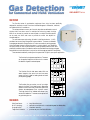
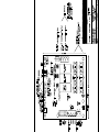
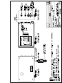
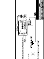
GAS-ALERT PLUS
User Manual
GAS-ALERT Series
THE SYSTEM
The Gas-Alert series of gas detection equipment from Arjay has been specifically
designed for ventilation control of toxic and combustible gases in commercial, industrial,
and residential HVAC installations
This series provides a common set of control relays that are dedicated to control
the fans within one area or zone. For multiple fan and zoning needs, the Arjay
66-RLU can be used; to provide one central panel or multiple Gas-Alert systems
can be used, one within each zone to provide the control box adjacent to
the dedicated fan.
The solid state sensor technology (Metallic Oxide Semiconductor - MOS)
provides a low cost and long life approach to gas ventilation. The sensor is calibrated
to a target gas selected for the application (ie. carbon monoxide in parking garages).
Other toxic gases that may influence the sensor in a similar fashion, such as gasoline
and paint fumes, will also initiate ventilation providing added protection from other
potentially hazardous vapors. Gas selective sensors are available where background gases
are preferred not to activate the fans in conjunction with the target gas (see Multi-Sense Series).
Three standard models will provide you with a system that is right for your specific application.
The Gas-Alert for single sensor applications. The sensor
can be supplied integral to the control unit or remote
for detection of gases in awkward spaces.
High Alarm
BAS
FANS
Low Alarm
Power
Integral OR remote
Sensor
GAS - ALERT
The Gas-Alert Plus for dual sensor needs. With one
sensor integral to the control unit and one sensor
remote, this unit is ideal for loading docks and small
private parking garages.
High Alarm
BAS
FANS
Low Alarm
Power
Integral AND remote
Sensor
GAS - ALERT PLUS
The Gas-Alert Max can monitor a run of up to eight
sensors in the field. This is ideal for use in larger areas
where a common alarm relay is sufficient without the
discrete acknowledgement from a specific sensor.
The single 4-wire run of shielded cable allows a very
economical installation. The sensors can be spliced into
any point along the run.
BAS
High Alarm
FANS
Power
Low Alarm
Up to 9 sensors
GAS - ALERT MAX
THE RESULTS
Solid State Sensor
MOS Technology
Single Wire Run
Target Gas Calibration
=
=
=
=
long life and low cost
responds to multiple toxic or combustible gases for added safety
installation economy
provides easy one man field calibration
A product of Enmet Canada Ltd. tel. (905) 829-4700 fax (905) 829-4701 www.EnmetGasDetection.com
GAS-ALERT SPECIFICATIONS
SENSOR:
VISUAL ALARMS:
RELAYS:
Metallic Oxide Semiconductor (MOS) technology with cintered filter housing for environmental conditioning. Diffusion sensing (no pumps). Plug-in design.
LED indication at sensor and controller
green (normal)
yellow (low alarm)
red (high alarm)
red (fault) (flashing at sensor, steady at controller)
5 amp @ 250 VAC, DPDT, Dry; one for high, one for low, one for fault
(on multiple sensor units, above relays are common to all sensors)
TIME DELAYS:
0-20 minute Delay On and Delay Off for each alarm relay
0-20 minute Delay On for audio signal
BAS INTERFACE:
Low Alarm:
High Alarm:
0 volts indicates normal, 24 VDC signal indicates alarm condition
0 volts indicates normal, 24 VDC signal indicates alarm condition
(for BAS acknowledgement only)
AUDIO OUTPUT:
24 vdc @ 50 mA for optional buzzer
On board audio silence (optional external mounted push button)
FAIL SAFE:
Field selectable for high or low for each relay
PUSH TO TEST:
On board push button for control function test (optional external mounted push button)
POWER INPUT:
115 VAC, 50/60 Hz or 24 VDC (.25 amp/sensor). Specify at time of order
TEMPERATURE:
-20 C to +60 C
HUMIDITY:
0 to 90% non-condensing. Equipment mounted in non-wetted areas only.
SENSOR LIFE:
Expected 3 to 5 years
MAINTENANCE:
Recommended minimum 3 gas calibrations per year. Frequency determined by application.
APPROVALS:
CSA, cUL and UL Electrical Safety.
TYPICAL GASES:
Typical Gases
Carbon Monoxide:
Ammonia:
A1 Refrigerants
B1 Refrigerants
Methane
Propane
Hydrogen
Typical Calibration Setpoints (2 levels/sensor)
ppm:
25, 35, 50, 75, 100, 200
ppm:
25, 35, 50, 100, 500
ppm:
1000 only, (R-11, R-12, R-22, R-134A)
ppm:
30 or 50 only, (R-123)
% lel: 5, 10, 15, 20, 25, 35, 40, 50
% lel: 5, 10, 15, 20
% lel: 10, 20
One target gas per sensor only. Multiple sensors may be calibrated to different gases along the same
wire run. Correlation gases and specialty calibrations are available. Specify calibration at time of order.
YOUR REPRESENTATIVE:
Enmet Canada Ltd.
Oakville (Toronto), Canada L6H 6C9
Tel: ++1 (905) 829-4700
1-800-367-4706 (Canada)
Fax: ++1 (905) 829-4701
[email protected]
www.EnmetGasDetection.com
10/99/gas-alert
MODEL
DOCUMENT TYPE
ENMET
USER MANUAL
GAS-ALERT PLUS
DOCUMENT FILE NAME
REV.
MgslPL20.doc
2.0
CREATE DATE
REV. DATE
PRINT DATE
08/25/97
06/16/2003
06/16/2003
TABLE OF CONTENTS
1.0
2.0
3.0
4.0
5.0
6.0
THEORY OF OPERATION........................................................................................................3
UNPACKING ..............................................................................................................................3
SENSOR LOCATION.................................................................................................................3
INSTRUMENT OVERVIEW......................................................................................................4
4.1
FEATURES ...................................................................................................................4
4.2
DESCRIPTION .............................................................................................................4
4.3
SPECIFICATIONS........................................................................................................4
INSTALLATION.........................................................................................................................5
5.1
MECHANICAL INSTALLATION...............................................................................5
5.2
ELECTRICAL HOOKUP .............................................................................................5
5.2.1
POWER ..................................................................................................................5
5.2.2
REMOTE SENSOR ...............................................................................................5
5.2.3
RELAYS.................................................................................................................5
5.2.4
BUILDING AUTOMATION SYSTEM (BAS) CONNECTION..........................6
5.2.5
AUDIBLE ALARM (Optional).............................................................................6
CALIBRATION AND SETUP....................................................................................................6
6.1
CALIBRATION OF INTEGRAL MOS SENSOR .......................................................6
6.2.1
CALIBRATING THE INTEGRAL SENSOR .......................................................6
6.2.2
SETTING THE TIME DELAY RELAYS .............................................................7
6.2.3
COMPLETION ......................................................................................................8
HARDWARE REV.
SOFTWARE REV.
1.0
N/A
Page 2 of 8
MODEL
DOCUMENT TYPE
ENMET
USER MANUAL
GAS-ALERT PLUS
DOCUMENT FILE NAME
REV.
MgslPL20.doc
2.0
CREATE DATE
REV. DATE
PRINT DATE
08/25/97
06/16/2003
06/16/2003
1.0
THEORY OF OPERATION
The Gas-Alert Plus is a single zone monitor with two alarm points which
employs Metallic Oxide Semiconductor (RLU MOS Series) sensing elements and/or
Electrochemical sensors (EC-Gold Series). In the presence of a gas, a
voltage output is produced. Depending on the specified gas level, this
output enables the activation of alarms, relays, etc. at desired levels. The
MOS technology is also referred to as Broad Range sensing because the
sensor will respond to a broad range of gases. The Electrochemical sensors
(EC-Gold Series) may be referred to ‘‘wet chem’’ or ‘‘near specific’’.
The sensor selected for this unit has been determined to be the most
suitable for your target gas. The unit and sensor have been calibrated to
specific alarm levels using the target gas for this application (i.e.
carbon monoxide).
Other toxic or combustible gases may also cause the sensor to respond and
alarm the unit. The sensors should be installed in areas where influencing
background gases are not constantly present.
Your Enmet gas detector is the state of the art in gas detection, but like
any other part of your ventilation system, it requires periodic maintenance
and calibration.
The MOS sensors and the Carbon Monoxide (EC-Gold) used in your new gas
detector will have a normal operating life of 3 to 5 years under ambient
conditions. The other EC-Gold Series sensors will last about 1-2 years.
You should consider a preventive maintenance schedule whereby you test your
system on a periodic basis to ensure its proper calibration and operation.
Most users have their unit tested every three to four months with test gas.
This is a simple procedure, which will indicate any problems with your
system. A sensor fault is indicated for the MOS and Carbon Monoxide (ECGold Series) sensor only. Other electrochemical sensors are not
acknowledged when their operating life has expired.
A test and calibration kit may be purchased from Enmet for this purpose.
Parts are also readily available from our facility.
2.0
UNPACKING
Inspect all parts of the gas detector upon receipt for any damages that may have occurred during shipping and that all
parts ordered were received. Contact Enmet Canada or your local representative if anything is in error or damage is
suspected.
3.0
SENSOR LOCATION
Gases of different molecular structures have different densities; some are heavier than air and concentrate at the
bottom of a space and some will rise.
The following is a general guide. For assistance in sensor location consult your Enmet Representative.
Carbon Monoxide
Methane
Ammonia
Propane
H2S
Freon
same as air
lighter than air
lighter than air
heavier than air
heavier than air
heavier than air
place about 4-6' above finished floor
place near ceiling
place near ceiling
place about 2' above finished floor
place about 2' above finished floor
place about 2' above finished floor
NOTE: Place sensors in a location that is easily accessible for calibration and testing. Mount so the sensors are
HARDWARE REV.
SOFTWARE REV.
1.0
N/A
Page 3 of 8
MODEL
DOCUMENT TYPE
ENMET
USER MANUAL
GAS-ALERT PLUS
DOCUMENT FILE NAME
REV.
MgslPL20.doc
2.0
CREATE DATE
REV. DATE
PRINT DATE
08/25/97
06/16/2003
06/16/2003
facing downward to avoid dust or debris collection on the sensor.
4.0
INSTRUMENT OVERVIEW
4.1
FEATURES
•
Supports one integral MOS sensor and up to 1 Enmet Remote MOS RLU Sensors or 2 Enmet Remote
MOS RLU Sensors or 5 Remote EC-Gold Series Sensors.
DPDT 250 VAC / 5A relay contacts for High, Low and Sensor Fault alarms
Adjustable / independent 0-20 minute time delay to on and delay to off for High and Low alarms
Independent Fail-Safe setting for High and Low alarms
Board level Audible alarm output with silencer. Remote audible alarm & silencer push-button optional
Adjustable time delay for Audible Alarm (delay starts after High alarm)
Board level Push to Test button. Remote Push to Test push-button optional.
Additional High and Low alarm outputs (+24V out) to Building Automation System (BAS)
•
•
•
•
•
•
•
4.2
DESCRIPTION
The Enmet Gas-Alert Plus detection systems offer the ability to monitor for a variety of gases. It offers DPDT
contacts for High, Low and Sensor Fault alarms. In addition, High and Low signals are also available for
connection to a Building Management System (BMS). High and Low alarms have independent Delay-ON and
Delay-Off time delays adjustable from 0 – 20 minutes (total of 4 delay adjustments).
4.3
SPECIFICATIONS
FUNCTION
Two level alarm system: High and Low Alarms plus Sensor Fault Alarm
SENSOR TYPE
MOS (Metal Oxide Semiconductor) or Electrochemical Sensor (EC-Gold)
GASES
CO, Propane, CH4, NH3, H2S, Cl2, NO2 (consult factory for others)
ALARM RELAYS
Relays
Contacts
Fail-Safe
Time Delay
BAS OUTPUTS
Signal output
Drive capability
3 DPDT relays for High, Low and Sensor Fault Alarms
250 VAC or 30 VDC @ 5A
Fail-Safe / non-fail-safe settings for all 3 relays
0 – 20 minutes. Independent Delay-On and Delay-Off for both High and
Low Alarm relays (total 4 delay adjustments)
High and Low Alarm status outputs. +24V when alarm is active, 0V if not.
The status signals reflect the alarm condition AFTER the corresponding
alarm delays i.e. the status signal is active while the corresponding alarm
light is active.
The status signals are meant to be connected to a BAS / PLC and are not
intended to drive any appreciable load. A 330 Ohm resistor protects each
output. Thus for a 500 Ohm load, the output voltage is 14.5V, and for a 1000
Ohm load the output voltage is 18.0V.
AUDIBLE ALARM (Optional)
Function
Activated on High Alarm. (After High Alarm Delay)
Drive capability
24V @ 50 mA max. If greater drive is required, use a slave relay.
Silencer
Push-button silencer (auto-reset). Connection for remote silencer pushbutton (optional)
Time Delay
0 – 20 minutes Delay – On. (In addition to High Alarm Delay-On).
DIAGNOSTICS
HARDWARE REV.
SOFTWARE REV.
1.0
N/A
Page 4 of 8
MODEL
DOCUMENT TYPE
ENMET
USER MANUAL
GAS-ALERT PLUS
DOCUMENT FILE NAME
REV.
MgslPL20.doc
2.0
CREATE DATE
REV. DATE
PRINT DATE
08/25/97
06/16/2003
06/16/2003
Push to Test push-button. Tests by forcing a Sensor Fault on the internal
sensor. Alarm lights, relays, and BAS status signals are tested. Note: the
time delay settings are still active during test. Adjust them to 0 minutes prior
to test if the time delays are not to be tested.
POWER
Internal sensor only
Remote Sensor System
115 VAC @ .5 A, when supplied with a power supply (220 VAC available)
24 VDC @ 0.5A max. (Standard).
24 VDC @ 0.5A + 0.25A per Remote MOS Sensor /100mA per
Electrochemical (EC-Gold Sensor)
MECHANICAL SPECIFICATIONS
Enclosure
Nema 4X, Epoxy Coated Steel
Dimensions
8” X 8” X 5”
Weight
6.5 lb.
ENVIRONMENTAL SPECIFICATIONS
Operating Temp.
-20 to 60 Deg. C
Relative Humidity
90% max. with no condensation.
5.0
INSTALLATION
5.1
MECHANICAL INSTALLATION
See Drawing 972307
5.2
ELECTRICAL HOOKUP
See drawing 972300
5.2.1
POWER
The standard power input is 24 VDC. If this is being used then locate the power supply connector at the
bottom left of the Gas-Alert Plus board and connect the 24 VDC as shown on drawing 972300. The
connector is a 2-conductor mating pair arrangement. The connector may be unplugged for ease of wiring.
If 115 or 220 VAC power is to be used then locate the separate VAC input power supply and connect the
Line, Neutral and GND connections as labeled on the back panel.
5.2.2
REMOTE SENSOR
The Gas-Alert Plus may have one integral MOS sensor and remote MOS/EC Gold sensors. The remote
MOS sensor is connected via a 4-conductor 16-18 gauge shielded wire, cable that carries power (2
conductors) and a common remote signal pair. The Electrochemical (EC-Gold Series) is connected via a 3
conductor 16-18 gauge shielded wire. See dwg 20010201 for more details.
Locate the Remote Sensor connector on the left edge of the Gas-Alert Plus board.
5.2.3
RELAYS
Three DPDT 250 VAC / 5A contact relays are provided: for High Alarm, Low Alarm, and Sensor Fault.
These relays are common to the integral sensor and the remote sensors, i.e. if the integral sensor or the
remote sensor is in low alarm then the Low Alarm relay and LED are activated.
Sensor Fault: If any MOS sensor (integral or remote) or the Carbon Monoxide (EC-Gold Series) is
removed then the Sensor Fault relay and LED are activated.
NOTE: Each relay may be set as Fail-Safe (normally energized, and de-energized on alarm condition) or
HARDWARE REV.
SOFTWARE REV.
1.0
N/A
Page 5 of 8
MODEL
DOCUMENT TYPE
ENMET
USER MANUAL
GAS-ALERT PLUS
DOCUMENT FILE NAME
REV.
MgslPL20.doc
2.0
CREATE DATE
REV. DATE
PRINT DATE
08/25/97
06/16/2003
06/16/2003
non-fail-safe (normally de-energized, and energized on alarm condition).
The connections are as shown on drawing 972300.
5.2.4
BUILDING AUTOMATION SYSTEM (BAS) CONNECTION
The Gas-Alert Plus provides external High and Low Alarm status signals (+24V when in alarm, 0 V when
not) for connection to a Building Automation System (BAS). The signals are non-isolated and are
referenced to the provided +24V power supply ground.
The connection is located on the right edge of the Gas-Alert Max board as shown on drawing 972300.
5.2.5
AUDIBLE ALARM (Optional)
The Audible Alarm connector (2 conductor) is located on the right edge of the Gas-Alert Plus board. The
connection is either to a Horn / Buzzer on the side panel (typical) OR connected to a remote horn / buzzer
(both optional). The output is +24V @ 50 mA (maximum current). Some horns / buzzers are polarity
sensitive i.e. make sure the + output is connected to the + terminal of the horn.
6.0
CALIBRATION AND SETUP
6.1
CALIBRATION OF INTEGRAL MOS SENSOR
The Gas-Alert Plus may have up to 2 RLU MOS sensors (all remote or one integral and the rest remote) or up
to 5 Electrochemical (EC-GOLD Series) sensors. The integral sensor may be only of the MOS technology.
See the following calibration procedures for the integral sensor. If other sensors are supplied, please find the
additional sensor manual(s) required at the end of this manual.
6.2.1
NOTE:
CALIBRATING THE INTEGRAL SENSOR
If an integral sensor is not being used a resister is factory jumpered across the input terminal
block (J9). Verify this is in place and proceed to 6.2.2
Calibrating the integral sensor requires:
•
Enmet Calibration Kit which should have calibration gas concentrations for the required High and
Low alarm values.
•
Small slot screwdriver to adjust the alarm levels.
•
The Gas-Alert Plus should be powered up for 48 hours prior to calibration to allow the sensor to
stabilize.
•
A Voltmeter.
1.
Locate Test Point 1 (named TP1: Black) (See drawing 972300). It is located at the bottom left of the
Gas-Alert Plus board. Locate Test Point 2 (named TP2: Red). It is located roughly an inch above
TP1. Plug the negative lead of the voltmeter into TP1 and the positive lead to TP2. The measured
voltage will be in the 1.5 – 5 Volt range.
2.
Locate the Range potentiometer (labeled N) on the top edge of the Gas-Alert Plus board. With the
small adjusting screw, adjust the pot. to get approx. 2.8 VDC (+/- .2) volts on the voltmeter in clean
air.
3.
Prior to calibration, adjust all 4 time delay pots to 0: fully counter clockwise. The delay adjust pots are
in a group of 4 located on the top left edge of the Gas-Alert Max board.
4.
SETTING THE LOW ALARM: Setup the Enmet calibration kit as per the Enmet calibration kit
drawing (see fig 1.0). You will need a gas canister containing the gas concentration of the low alarm
level (i.e. if the low alarm is to be set at 35 PPM Carbon Monoxide then the canister should contain 35
HARDWARE REV.
SOFTWARE REV.
Page 6 of 8
1.0
N/A
MODEL
DOCUMENT TYPE
ENMET
USER MANUAL
DOCUMENT FILE NAME
REV.
MgslPL20.doc
2.0
GAS-ALERT PLUS
CREATE DATE
REV. DATE
PRINT DATE
08/25/97
06/16/2003
06/16/2003
PPM Carbon Monoxide). Attach the calibration cup over the Gas-Alert Plus integral sensor and adjust
the gas flowrate to about 0.75 – 1 SCFH. Note: the use of the voltmeter is optional, but is useful to
determine the length of the calibration time. The sensor requires roughly 1 to 2 minutes to stabilize or
until the voltage drop stabilizes.
5.
Locate the Low Alarm adjustment pot. labeled “L” in drawing 972300. It is located on the top edge of
the Gas-Alert Plus board.
6.
Also locate the Low Alarm indicator LED (Yellow) which is below the adjustment pots. After the
sensor has stabilized, if the Low Alarm LED is already lit then adjust the Low Alarm pot. clockwise
until the alarm LED just goes off then adjust it counterclockwise until the LED just comes on, plus 10
degrees. If the LED is already off, adjust the pot. counterclockwise until the LED just goes on, plus
10 degrees.
7.
Repeat steps 4 – 6 for the High Alarm using the high level calibration gas, but in this case, use the pot.
marked “H” to adjust the alarm, and the leftmost RED LED for the High Alarm indication. See 6.2.3.
THE COMPONENTS IN YOUR KIT
TUBING
Flexible, clear
tubing.
BUBBLER
SENSOR CAP
Humidifies the gas through
tap water (fill to mark, note
arrow direction).
Fits snugly over sensor to block
out outside air during
calibration
REGULATOR
Allows a regulated gas flow
from the canister.
TUBING
Replacement canisters an
parts available from your
nearest representative.
GAS CANISTER
Calibration gas. Disposable
after completely empty.
ROTOMETER
Indicates gas flow rate
to sensor (regulate to 1.0 SCFH)
Figure 1.0
6.2.2
SETTING THE TIME DELAY RELAYS
1.
SETTING THE ALARM DELAYS: The High Alarm Delay-On is the leftmost pot. on the top edge of
the Gas Alert board, while the Delay-Off is the 2nd from the left. On delay means relay state will
change after “X” minutes after concentration level reaches. Off delay means relay state will stay on
“X” minutes after concentration levels are back to normal. Locate the Low Alarm delay pots which
are on the top edge of the Gas-Alert Plus board and are the 3rd and 4th pots from the left edge. See
drawing 972300 for placement. The Delay-On is the leftmost of the group of 2 (3rd from the left
edge). Adjust the pots for the desired time delays. Full scale is about 20 minutes so half way is about
10 minutes. This concludes the Low Alarm setup.
2.
TIP: Setting the delay “ON” for a few minutes will allow the unit to ignore spurious alarms caused by
sudden clouds of gas momentarily passing over the sensor. Setting the delay “OFF” for a determined
time will keep the fans operating after the sensor has cleared to ensure remote areas from the sensor
are also clear.
3.
SETTING THE HORN DELAY: The audible alarm (optional) is triggered by the High Alarm. The
audible alarm delay is therefore in addition to the High Alarm delay. The sequence is as follows:
when the gas concentration is higher than the high alarm setpoint for at least the high alarm Delay-On
HARDWARE REV.
SOFTWARE REV.
1.0
N/A
Page 7 of 8
MODEL
DOCUMENT TYPE
ENMET
USER MANUAL
GAS-ALERT PLUS
DOCUMENT FILE NAME
REV.
MgslPL20.doc
2.0
CREATE DATE
REV. DATE
PRINT DATE
08/25/97
06/16/2003
06/16/2003
then the high alarm relay and indicator (RED) are activated. At this time the audible alarm is also
triggered. After an additional time as set by the horn delay, the audible alarm is turned on and
continues until either the High alarm is deactivated or the silencer switch (Board mounted) is pressed.
The horn time delay also has a 0-20 minute scale. The horn may thus be turned on a maximum of
about 40 minutes after the sensor senses a high alarm (High Alarm Delay-On plus the Horn DelayOn).
6.2.3
COMPLETION
Replace the cover on the sensor and control box. Remove the flow gauge from the calibration gas.
Calibration is complete.
HARDWARE REV.
SOFTWARE REV.
1.0
N/A
Page 8 of 8