1
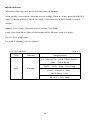
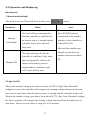
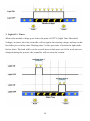
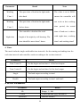
ViewStar series —— Solar Charge Controller OPERATION MANUAL Thank you very much for selecting our product! This manual offers important information and suggestions with respect to installation, use and troubleshooting, etc. Please read this manual carefully before using the product and pay attention to the safety recommendations in it. ViewStar —— Solar Charge Controller Nominal system voltage 12V⁄24V⁄36V⁄48V Nominal charge / discharge current 10A⁄20A⁄30A⁄45A⁄60A Final interpretation right of the manual belongs to EPsolar. Any changes without prior notice! Contents 1 Important Safety Information.......................................................................................... 1 2 General Information........................................................................................................ 2 2.1 Product Overview............................................................................................... 2 2.2 Product Features................................................................................................. 4 2.3 Optional Accessories.......................................................................................... 6 3 Installation Instructions................................................................................................... 7 3.1 Mounting............................................................................................................ 7 3.2 Wiring................................................................................................................ 9 4 Operation.......................................................................................................................12 4.1 PWM Technology............................................................................................ 12 4.2 Battery Charging Information...........................................................................12 4.3 HMI Interface................................................................................................... 15 4.4 Operation and Displaying of Controller............................................................17 4.5 Remote communication and monitor................................................................43 5 Protection, Troubleshooting and Maintenance.............................................................. 45 5.1 Protection......................................................................................................... 45 5.2 Troubleshooting................................................................................................46 5.3 Maintenance..................................................................................................... 49 6 Technical Specifications................................................................................................50 1 Important Safety Information Save These Instructions This manual contains important safety, installation and operating instructions. The following symbols are used throughout this manual to indicate potentially dangerous conditions or mark important safety instruction. WARNING: Indicates a potentially dangerous condition. Use extreme caution when performing this task. CAUTION: Indicates a critical procedure for safe and proper operation of the controller. NOTE: Indicates a procedure or function that is important for safe and proper operation of the controller. General Safety Information Read all of the instructions and cautions in the manual before installation. There are no user serviceable parts inside the controller. Do not disassemble or attempt to repair it. Mount the controller indoors. Prevent exposure to the elements and do not allow water to enter the controller. Install ViewStar controller in well ventilated places, the ViewStar controller heatsink may become very hot during operation. Install external fuses/breakers as required. Disconnect the solar module, load and fuse/breakers near to battery before installing or adjusting the controller. Power connections must remain tight to avoid excessive heating from a loose connection. 1 2 General Information Thank you for selecting ViewStar series solar charge controller. The controller adopts advanced digital control technology, LCD display and automatical operation. With the features of Pulse Width Modulation (PWM) battery charging and unique control technology, the controller will improve the long battery life efficiently. Our controller has many unique features and easy to use. 2.1 Product Overview The controller could charge battery and discharge automatically for off-grid photovoltaic (PV) systems. The charging process has been optimized for long battery life and improved system performance. The comprehensive self-diagnostics and extensive electronic protection can prevent damage against incorrect wiring or system faults. Features: 32 bit MCU with high speed and high performance 12 bit A/D high-precision sampling to ensure accuracy Excellent EMC design Nominal system voltage automatic recognition or user-defined working voltage High efficient Series mode PWM charging, increase the battery lifetime and improve the solar system performance Use MOSFET as electronic switch, without any mechanical switch Wide feasibility and, recognize day or night automatically Graphical dot-matrix LCD and 4 buttons combinations as HMI (human-machine interface) for full menu and easy operation Humanized design of browser interface to facilitate the operations All of control parameters could be set and modified Several load control methods are supported to convenient for different demand Support 4 charging preprogram options: Sealed, Gel, Flooded and User-defined Adopt temperature compensation and update charging and discharging parameters automatically to improve the battery lifetime With the feature of input filter, the voltage spike could be restrained effectively 2 Actual Power Display and record function make convenience to check the datum every day, every month and every year RS-485 ports via the open standard Modbus protocol are supported for long-distance communication and communication compatibility Standard RJ45 interface is used to connect to remote display unit (MT50) or PC software to monitor the actual data or modify parameters New SOC method could calculate the battery capacity accurately Electronic protection: Overheating, over discharging, overload, and short circuit Reverse protection: any combination of solar module and battery 3 2.2 Product Features VS1024BN / VS2024BN 4 1 – Local temperature sensor It is used to acquire ambient temperature to do temperature compensation for charging and discharging. 2 – Fault LED indicator An LED indicator that shows system faults 3 – Charging LED indicator An LED indicator that shows charging status 4 – Liquid crystal display (LCD) Monitoring interface for solar system parameters and running status 5 –Buttons 4 buttons used to operate and configure controller 6 – Communication port Connect remote display unit MT50(Optional Accessories) or PC software 7 – Load terminals Connect loads. 8 – Battery terminals Connect batteries. 9 – Solar module terminals Connect solar modules 10 – Remote temperature sensor interface(optional) Connect remote temperature sensor (Optional Accessories) to acquire ambient temperature 11 – Battery slot Mount cell battery(RTC) 5 2.3 Optional Accessories 1. Remote Display Unit (Model:MT50) The remote display unit is used to monitor system operating information, faults and modify the parameters with displaying on a backlit LCD. The large numerical display and icons are easy to read and large buttons make menus easy to navigate. The unit can be mounted in the wall or the mounting frame. One 2m long cable are attached (the length of cable can be customized) and the mounting box is optional. The MT50 connects to controller through the RJ45 port. 2. Remote temperature sensor (Model:RTS300R47K3.81A) Remote temperature sensor is used to acquire ambient temperature to undertake temperature compensation for charging and discharging. Standard length of the cable is 3m (could be customized). The RTS300R47K3.81A connects through the 2P-3.81 port. Note: unplug the RTS, the temperature of battery will be set to a fixed value 25 ºC. 3. Super Parameter Programmer (Model: SPP-01) The Super Parameter Programmer can realize one-key setting operation which is suitable for bulk quantity products setting in the projects. 4. USB To RS-485 converter (Model:CC-USB-RS485-150U) USB To RS-485 converter is used to monitor each controller on the network using EPsolar Station PC software and update the firmware. The length of cable is 1.5m. The CC-USB-RS485-150U connects to the Communication port (6th) on the controller. 6 3 Installation Instructions 3.1 Mounting Read through the entire installation section first before beginning installation. Be very careful when working with batteries. Wear eye protection. Have fresh water available to wash and clean any contact with battery acid. Uses insulated tools and avoid placing metal objects near the batteries. Explosive battery gasses may be present during charging. So well ventilation of battery box is recommended. Avoid direct sunlight and do not install in locations where water can enter the controller. Loose power connections and/or corroded wires may result in resistive connections that melt wire insulation, burn surrounding materials, or even cause fire. Ensure tight connections and use cable clamps to secure cables and prevent them from swaying in mobile applications. Gel, Sealed or Flooded batteries are recommended, other kinds please refer to the battery manufacturer. Battery connection may be wired to one battery or a bank of batteries. The following instructions refer to a singular battery, but it is implied that the battery connection can be made to either one battery or a group of batteries in a battery bank. Select the system cables according to 3A/mm2 current density. CAUTION: The ViewStar controller requires at least 150mm of clearance above and below for proper air flow. Ventilation is highly recommended if mounted in an enclosure. WARNING: Risk of explosion! Never install the controller in a sealed enclose with flooded batteries! Do not install in a confined area where battery gassed can accumulate. 7 Step 1: Choose Mounting Location Locate the controller on a vertical surface protected from direct sun, high temperature, and water. And make sure good ventilation. Step 2: Check for clearance Place the controller in the location where it will be mounted. Verify sufficient room to run wires and sufficient room above and below the controller for air flow. 150mm(5.9inches) Warm air 150mm(5.9inches) Cool air Step 3: Mark Holes Mark the four (4) mounting hole locations on the mounting surface. Step 4: Drill Holes Remove the controller and drill 4mm holes in the marked locations. Step 5: Secure Controller Place the controller and align the mounting holes with the drilled holes in step 4. Secure the controller in place using the mounting screws. 8 3.2 Wiring NOTE: A recommended connection order has been provided for maximum safety during installation. NOTE: the controller is common negative one. CAUTION: Don’t connect the loads with surge power exceeding the ratings. CAUTION: Secure all wiring for mobile applications. Use cable clamps to prevent cables from swaying. Unsecured cables create loose and resistive connections which may lead to excessive heating and/or fire. WARNING: Risk of explosion or fire! Never short circuit battery positive (+) and negative (-) or cables. WARNING: Risk of electric shock! Exercise caution when handling solar wiring. The solar module(s) high voltage output can cause severe shock or injury. Be careful operation when installing solar wiring. If nominal system voltage is 12V, make sure battery voltage is higher than 9V before starting the controller. If nominal system voltage is 24V, make sure voltage of battery is no less than 18V; if nominal system voltage is 36V, make sure voltage of battery is no less than 30V; if nominal system voltage is 48V, make sure voltage of battery is no less than 42V. The nominal system voltage can only be identified when controller is powered 9 on automatically. Controller’s load terminals can be connected to DC electric equipments whose nominal operation voltage is the same as nominal voltage of battery. The controller supplies power to loads with battery voltage. It is suggested that positive pole or negative pole of battery and loads be connected to a safety device whose operation current is not twice lower than nominal charging or discharging current. Do not switch on the safety device while it is being installed. Switch on the safety device after the wiring is confirmed. CAUTION: On occasions that controller must be connected to the ground. For common positive controller, the positive pole must be connected to the ground, on the contrary, the negative pole must be connected to the ground for common negative controller. * Wire conductor length: VS1024BN :7mm VS20**BN :13mm VS30**BN :10mm VS45**BN / VS60**BN :14mm 10 Step 1: Wiring and switching on After solar system is wired, check all wirings carefully to make it clear whether all 6 terminals are connected correctly and tightened. According to the order of switching on in the chart, battery first, loads second and solar module third successively to avoid nominal system voltage identification error. 3 Solar Array Load + - + - + - Fuse 1 2 Battery Step 2: Power on When controller starts up, liquid crystal display (LCD) displays initialization interface and 2 indicator LED will be blinked once. Check if it is correct. If there are no above procedures, refer to section 5 for troubleshooting. 11 4 Operation 4.1 PWM Technology (Series Pulse Width Modulation) The controller adopts the advanced series pulse width modulation (PWM) charging mode. With range of 0-100%, it can charge the battery quickly and stably under any condition of solar photovoltaic system. PWM charging mode use automatic conversion duty ratio pulses current to charge the battery. The battery can be fully charged safety and rapidly with the pulse current. Intermissions make oxygen and hydrogen generated by chemical reaction combined again and absorbed. It can eliminate concentration polarization and ohm polarization naturally and reduce the internal pressure of the battery so that the battery can absorb more power. Pulse current charging mode makes battery have more time to react which reduces the gassing volume and makes battery improve the acceptance rate of charging current. 4.2 Battery Charging Information ·Bulk Charge In this stage, the battery voltage has not yet reached boost voltage and 100% of available solar power is used to charge the battery. ·Boost Charge When the battery has recharged to the Boost voltage setpoint, constant- current regulation 12 is used to prevent heating and excessive battery gassing. The Boost stage remains 120 minutes and then goes to Float Charge. Every time when the controller is powered on, if it detects neither over discharged nor overvoltage, the charging will enter into boost charging stage. ·Float Charge After the battery is fully charged in Boost voltage stage, the controller reduces the battery voltage to Float voltage set point. When the battery is fully recharged, there will be no more chemical reactions and all the charge current transmits into heat and gas at this time. Then the controller reduces the voltage to the floating stage, charging with a smaller voltage and current. It will reduce the temperature of battery and prevent the gassing, also charging the battery slightly at the same time. The purpose of Float stage is to offset the power consumption caused by self consumption and small loads in the whole system, while maintaining full battery storage capacity. In Float stage, loads can continue to draw power from the battery. In the event that the system load(s) exceed the solar charge current, the controller will no longer be able to maintain the battery at the Float setpoint. Should the battery voltage remains below the boost reconnect charging voltage, the controller will exit Float stage and return to Bulk charge. · 13 Equalize Charge WARNING: Risk of explosion! Equalizing flooded battery can produce explosive gases, so well ventilation of battery box is necessary. NOTE: Equipment damage! Equalization may increase battery voltage to the level damaging to sensitive DC loads. Ensure that all load allowable input voltages are greater than the equalizing charging set point voltage. NOTE: Equipment damage! Over-charging and excessive gas precipitation may damage the battery plates and activate material shedding on them. Too high an equalizing charge or for too long may cause damage. Please carefully review the specific requirements of the battery used in the system. Certain types of batteries benefit from periodic equalizing charge, which can stir the electrolyte, balance battery voltage and complete chemical reaction. Equalizing charge increases the battery voltage higher than the standard complement voltage which gasifies the battery electrolyte. Every month 28th solar controller will engender equalize charging stage. It will remain 120mins when equalize stage is constant, or it will remain 180mins when equalize charging accomplishes off and on. Equalize charge and boost charge are not carried out constantly in a full charge process to avoid too much gas precipitation or overheating of battery. 14 4.3 HMI Interface Charging indicator Fault indicator LCD WELCOME V2.35+V2.63 ! MENU/← ↑/ + ↓/ - ENTER/→ ■ Buttons instruction: Cursor down / Number reduce button Cursor up / Number add button Menu / Cursor left button Enter / cursor right button Charging indicator GREEN ON whenever sunlight is available for battery charging and the charging system is normal. Charging LED indicator Table 4-1 Color Indicator Charging Status Green Steady On Charging 15 Fault indicator When the following cases occur, fault indicator red flashing: Solar module: Over current, Measure error of voltage, Short of reverse-protection MOS-I, Short of charging MOS-C, MOS-I or MOS-C disconnection or MOS break in control section; Battery: Over voltage, Measure error of voltage, Over temp; Load: Over load, Short, Short of discharging MOS, Measure error of voltage; Device: Over temperature. For trouble shooting, refer to chapter 5. Fault LED indicator Color Table 4-2 Indicator Charging Status PV:Measure Err、MOS-I Short、MOS-C Short、 MOS Break Red Flashing BATT:OVD、Error、Over Temp LOAD:Overload、Short、 MOS Short、Error DEVICE:Over Temp 16 4.4 Operation and Displaying Load mode 1.Manual mode(default) This mode is to turn ON and OFF the load by press Parameter Manual ON(default) Detail Note The load will open automatically Press ENTER button to after the controller is initialized. If control load at the standby the battery power is enough and the interface in the controller or controller works well, load will in the MT50/100; keep open The load also could be got The load will keep off after the controller is initialized. Only when Manual OFF button. open load manually, load can be through or shut down by monitor software in remote PC; output. If the battery power is enough and the controller works well, load will keep open 2.Light On/Off When solar module voltage goes below the point of NTTV (Night Time Threshold Voltage) at sunset, the controller will recognize the starting voltage and turn on the load after pre-set time delay when the battery power is enough and the controller works well. When solar module voltage goes above the point of DTTV (Day Time Threshold Voltage), the solar controller will recognize the starting voltage and turn off the load after pre-set time delay. The pre-set time delay is range of 0 to 99 minutes. 17 3. Light ON + Timer When solar module voltage goes below the point of NTTV (Night Time Threshold Voltage) at sunset; the solar controller will recognize the starting voltage and turn on the load after pre-set delay time. Working time 2 is the open time of load in the light mode before dawn. The load will be on for several hours which users set. If the work time are changed during the process, the controller will not reset the counter. 18 Parameter Detail Note Working The open time of load in the light mode The value is set to ZERO after dusk means the controller will The open time of load in the light mode not work at this working before dawn time period; the actual The controller calculated the total time of load-on is relative length of the night by self-learning. The with night time, working time should be more than 3 hours time1 and working time2 Time 1 Working Time 2 Night time 4. Timer The mode includes single and double time intervals. Set the starting and ending time for each time interval and controller works according to the set time interval. Parameter Detail Time Control 1 Set the begin and end time 1 of the load output Time Control 2 Set the begin and end time 2of the load output Single The load output according to time1 Double The load output according to time1 and time2 ● Device Parameters Parameter Detail ID Range: 1 - 200 Clock Format:dd-mm-yyyy hh-mm-ss Password Default: 000000 19 ● Battery Charging Setting Battery Type Note Sealed (default) GEL flooded Constant value Constant value Constant value User Defined by user 20 Operation and displaying of controller Initialization Interface When controller is powered on, the following picture will be painted during the initialization: WELCOME V2.36 + V2.63 Main Menu Interface After controller is initialized, the monitoring interface will update automatically. Press button to main menu 1 interface which displays the following contents: 1.Monitoring 2.Device Set Press 3.Parameter Set Inverse cursor showing the 4.Load Set contents can be operated button to enter into main menu 2 and main menu 3 interface which displays the following contents: 5.Rated Value 9.Factory Reset 6.Test Mode 10. Reboot Device 7. Password 8. Batt Mng Mode 21 System Monitor Interface In the main menu interface, press or , the inverse cursor moves between main menu 1 and main menu 2.When the inverse cursor points at 1. Monitoring in the main menu 1, press to enter into the system monitoring interface which displays contents as below. Press or t display every real-time parameters interface circularly. ▼Solar array voltage and current The interface shows real-time voltage and current of solar module. PV 14.5V 7.2A ▼ Battery voltage and current Press to enter into the following interface which shows actual battery voltage and current. Minus sign with current means that the battery is in discharging status. Positive sign means the battery is in charging. BATT 12.5V —5.5A ▼ Battery temperature and battery SOC Press to enter into the following interface which indicates actual temperature and SOC of battery. 22 TEMP 25.6 °C SOC: 47% ▼ Load voltage and current Press and enter into the following interface which indicates actual voltage and current of loads. LOAD 12.5V 5.5A ▼ Real-time clock and imaging system status Press and enter into the following interface which indicates real-time clock and graphic system status. If choose the manual mode with loads, press the interface to control loads on and off alternatively. Sep05 12 : 24 : 23 23 in ■ Introductions to system status icons: ﹡ :Day :Night :Charging :Normal :LVD :Normal :UVW :LVD :ON :OFF Icons indicating battery charging are dynamic effects. ▼ System status Press and enter into the following interface which indicates system status. PV : Disconnect BATT : NoCharge / Normal LOAD : On DEVICE : Normal 24 PV status: Connect Disconnect Measure Err MOS-I Short MOS-C Short MOS Break BATT charging status: Equalize Boost Float No Charge BATT status: LVD UVW Normal OVD Error OverTemp LOAD status: On Off OverLoad Short Error MOS Short DEVICE status: Normal ﹡ OverTemp When fault with inverse cursor above exists for 2 minutes along without any operation, it will jump into that page automatically. ▼ Charging energy statistics Char. Energy Day: 1.17KWh Mon: 25.35KWh Total: 98.74KWh 25 ▼ Discharging energy statistics Disch. Energy Day: 0.75KWh Mon: 18.53KWh Total: 54.32KWh Device Setting In the main menu, press or point to 2.Device Set, press button to make the inverse cursor to enter device setting interface which displays the following contents. When setting in this interface, real time clock will stop running. Please correct real time clock again after parameters are changed. Device Set Device Set Date : 12 – 05 - 2011 ID: 001 Time : 12 : 24 : 23 In the interface, press every parameter. Pressing Backlight: 010 sec or , the inverse cursor moves among button could move the inverse cursor back to main menu. When inverse cursor points at the parameter, the contents of the parameter can be modified. press to increase the value and press to decrease the value. LCD backlight auto-off time can be set between 00 ~999 seconds. The below message box will be prompted after press or to choose save or cancel operation. When . Press modification canceled, the interface will go back main menu.. Auto-off time of LCD backlight is 60 seconds as default. 26 Save Parameters Save Cancel If save confirmation is chosen, the system will automatically check the validity of parameters. If the check is passed, the promptation of successful saving will occur below. After parameters successfully saved, it returns to main menu interface. SAVE SUCCESS! Press and hold both and button for 3 seconds to enter factory mode in the main interface. The authority code to clear Energy Log is 102206 as default. The clear operation can’t be recalled, so take care! Device Set ID : 001 Backlight : 060sec Energy Log : Clear 27 Charging and Discharging Parameters Setting Interface press to enter into charging and discharging parameters setting interface as inverse cursor at 3.Parameter Set in main menu 1. press , it moves back to the previous interface and the inverse cursor points to the position of the first parameter. The following control voltage parameters value must be between 9v and 17v and in strictly accordance with: High Volt Disconnect > Charging limit voltage ≥ Equalization voltage ≥ Boost voltage ≥ Float voltage > Boost return voltage; High Volt Disconnect > Over Voltage Reconnect; Low voltage reconnect > Low voltage disconnect ≥ Charging limit voltage; Under voltage recover > Under voltage warning ≥ Charging limit voltage; Boost return voltage > Low voltage reconnect; ▼ Temperature compensation coefficient Press or , then the inverse cursor moves among every parameters sequencely. Press or compensation coefficient. Parameter Set Temp Compensate Coeff -03.0mV / ºC / 2V 28 to modify temperature ▼ Control parameters interface 1 Press continuously and the inverse cursor will move to the control parameters interface. Press or to modify the following control parameters. The value in this interface could be modified only when the battery type is USER defined. Parameter Set Over Volt. Disc : 16.0V Charg Lmt : 15.5V Over Volt. Rect : 15.0V ▼ Control parameters interface 2 Press continuously and the inverse cursor will move to the control parameters interface. Press or to modify the following control parameters. The value in this interface could be modified only when the battery type is USER defined. Parameter Set Equal Chrg : 14.6V Boost Chrg : 14.4V Float Chrg : 13.8V 29 Value is none when GEL battery ▼ Control parameters interface 3 Press continuously and the inverse cursor will move to the control parameters interface. Press or to modify the following control parameters. The value in this interface could be modified only when the battery type is USER defined. Parameter Set Boost V. Rect : 13.2V Under V. Rect :12.2V Under V. Warn:12.0V ▼ Control parameters interface 4 Press continuously and the inverse cursor will move to the control parameters interface. Press or to modify the following control parameters. The value in this interface could be modified only when the battery type is USER defined. Parameter Set Low V. Rect : 12.6V Low V. Disc : 11.1V Discharg Lmt : 10.6V 30 ▼ Control parameters interface 5 Press continuously and the inverse cursor will move to the control parameters interface. Press or to modify the following control parameters. Parameter Set Equa.Time : 120Min BoostTime : 120Min Range from 0 to 180 Range from 10 to 180 The interface below will prompt only when the SOC is selected in the Batt Mng Mode. Parameter Set Charge : 100% Discharge : 30% Constant value Range from 10 to 80 Only when the inverse cursor moves to the last option, the modified parameters could be saved. Press Press and the following picture appears. or to choose save or cancel operation. When modification canceled, the interface will go back main menu. Parameter Set Under V. Warn : 12.0V Save Cancel Low V. Disc : 11.1V Discharg Lmt : 10.8V 31 When save operation confirmed, the indication of successful saving will prompt as follows. After parameters successfully saved, it returns to main menu interface. Parameter Set Under V. Warn : 12.0V SAVE SUCCESS! Low V. Disc : 11.1V Discharg Lmt : 10.8V Load Control Interface When the inverse cursor rests on 4.Load Set in main menu 1, press and enter load control interface with the following contents displayed. Manual Light On / Off Light On + Timer Time ﹡When set light control threshold voltage, it should meet the requirement , refer to Chapter 6 Threshold Voltage Value. ▼ Manual control interface When the inverse cursor rests on Manual in main menu 1, press manual load control interface with the following contents displayed. 32 and enter Manual Default ON OFF Press or press and the messagebox below will prompt. When it is cancelled, the to choose ON or OFF as default. After confirmation, inverse cursor moves back to the main menu interface. Manual Default Save ON Cancel OFF When save confirmation chosen, the indication of successful saving will occur as follows. After parameters successfully saved, it returns to main menu interface. Manual Default SAVE SUCCESS! OFF ON ▼ Light control interface When the inverse cursor is at Light On / Off, press interface shown as below: 33 to enter light control Light On/Off Press sequencely. Press On : 05.0 V Delay :10 m Off : 06.0 V Delay :10 m or , the inverse cursor moves among each parameters or to modify the values. The below message box will be prompted after press Enter. Press or to choose save or cancel operation. When modification canceled, the interface will go back main menu. Light On/Off On : 06.0 V Save Delay :10 m Cancel Off : 05.0 V Delay :10 m When save operation confirmed, the indication of successful saving will prompt as follows. After parameters successfully saved, it returns to main menu interface. Light On/Off On :SAVE 06.0 V SUCCESS! Delay :10 m Off : 05.0 V Delay :10 m ▼ Light control + timer control interface When the inverse cursor is at Light On + Timer, press control and time control interface. 34 to enter into light Light On + Timer On : 05.0 V Delay :10 m Off : 06.0 V Delay :10 m Night Time : 10 : 00 Light On + Timer Press or Period 1: 01:00 Period 2: 01:00 to modify each parameter. The below message box will be prompted after press save or cancel operation. When . Press or to choose modification canceled, the interface will go back main menu. Light On + Timer Save Cancel Work Time : 10 : 00 : 00 When save operation confirmed, the indication of successful saving will prompt as follows. After parameters successfully saved, it returns to main menu interface. 35 Light On + Timer On : 06.0 V Delay :10 m SAVE SUCCESS! Off : 05.0 V Delay :10 m Work Time : 10 : 00 : 00 NOTE: When the “OFF” time is later than local sunrise time, the controller will turn off the load output at the sunrise time, because light control’s priority level is higher! ▼ Time control interface When the inverse cursor rests on Time in the time control interface, press enter into time control interface. Press or to to modify all parameters of time interval 1. Time Control 1 On Time : 07 : 20 : 00 Off Time : 15 : 00 : 00 When Press Press is continuously pressed, it will enter into the following interface. or or , the inverse cursor moves among every parameters. to modify value of time interval 2. When choosing Double time control mode, the load output will accord to time1 and time2. 36 Time Control 2 On Time : 16 : 30 : 00 Off Time : 06 : 00 : 00 Single Double * In the double time control mode, time1 and time2could not overlap. When choosing Single, only value of time1 can be modified. The interface is as follows: Time Control 2 On Time : -- : -- : -Off Time : -- : -- : -Single If changing the time, press Double to submit and the following message will prompt: Time Control 2 On Time : 19 : 20 : 00 Save Cancel Off Time : 07 : 00 : 00 Single Press or Double to select “save” to confirm update or cancel. After confirmed, the cursor will move back to the main menu. 37 When updating successfully, the prompt will show below and then move back to the main menu. Time Control 2 On Time : 19 : 20 : 00 SAVE SUCCESS! Off Time : 07 : 00 : 00 Single Double Nominal Parameter Interface press or , move inverse cursor to 5.Rated Value, then press button to enter into nominal parameter interface below. Battery rate and capacity can be modified. the batter rate are 12v, 24v, 36v, 48v or auto. Battery capacity ranges from 1 to 9999AH in the interface,. Press or to increase or decrease the value. Rated Value Batt : 12.0 V 0070AH Load : 10.0A PV : 10.0A Type : Gel If changing the value, press prompt: Press to submit and the following message will or to select “save” to confirm update or cancel. After confirmed, the cursor will move back to the main menu. 38 Rated Value Batt : 12.0 V Save Cancel Load : 10.0A PV : 10.0A Type : Seal Gel Flood When updating successfully, the prompt will show below and then move back to the main menu. Rated Value Batt : 12.0 V SAVE SUCCESS! Load : 10.0A PV : 10.0A Type : Seal Gel Flood Test Mode Interface Press or , move inverse cursor to 6.Test Mode, then press and enter into test mode interface below: Test Mode Load:> ON OFF Password Setting Interface Press or , move inverse cursor to 7.Password , then press and enter into test mode interface below: 39 Password Ori. PSW: 000000 New PSW: 000000 If changing the value, press prompt: Press to submit and the following message will or to select “save” to confirm update or cancel. After confirmed, the cursor will move back to the main menu. Time Control 2 Save Parameters On Time : 19 : 20 : 00 Save Cancel Off Time : 07 : 00 : 00 Double Single When updating successfully, the prompt will show below and then move back to the main menu. SAVE SUCCESS! 40 Battery Charge Mode Setting Interface Press or press and enter into test mode interface below: , move inverse cursor to 8.Batt Mng Mode, then Batt Mng Mode V.C. If changing the value, press prompt: Press SOC to submit and the following message will or to select “save” to confirm update or cancel. After confirmed, the cursor will move back to the main menu. Time Control 2 Save Parameters On Time : 19 : 20 : 00 Cancel OffSave Time : 07 : 00 : 00 Double Single When updating successfully, the prompt will show below and then move back to the main menu. SAVE SUCCESS! 41 Factory Reset Mode Interface Press or , move inverse cursor to 9.Factory Reset , then press and enter into test mode interface below: Factory Reset NO If changing the value, press prompt: Press YES to submit and the following message will or to select “save” to confirm update or cancel. After confirmed, the cursor will move back to the main menu. Factory Reset OK Cancel NO YES When updating successfully, the prompt will show below and then move back to the main menu. Factory Reset RESET SUCCESS! NO YES 42 Reboot Device Setting Interface Press or press and enter into test mode interface below: , move inverse cursor to 10.Reboot Device , then Reboot Device No Yes If needing to reboot the device, press to submit and the device will reboot at once. 4.5 remote communication and monitor With special communicate cable, user could monitor the status and modify the parameters. 1- MT50 display unit( need one standard twisted-net cable, model: CC-RS485-RS485-200U-MT) 2- Super parameter programmer, SPP-01(Use standard twisted net cable, model: CC-RS485-RS485-200U). One-key easily configure and apply to batch setting. 43 3- PC monitor software(need one private usb to rs485 cable, model: CC-USB-RS485-150U) WARNING: Do not use the standard twisted-net cable to connect the device and PC net interface, or the permanent damage will occur. 44 5 Protection, Troubleshooting and Maintenance 5.1 Protection • PV Array Short Circuit If PV array short circuit occurs, clear it to resume normal charge automatically. • Load Overload If the load current exceeds the rated current of controller(≥1.05 times rated discharge current), the controller will disconnect the load. Overloading must be cleared up, then pressing the switch button. • Load Short Circuit Fully protected against load wiring short-circuit(≥2 times rated discharge current). After one automatic load reconnect attempt, the fault must be cleared by restarting the controller or pressing the switch button. • PV Reverse Polarity Fully protection against PV reverse polarity, no damage to the controller will result. Correct the miswire to resume normal operation. • Battery Reverse Polarity Fully protection against battery reverse polarity, no damage to the controller will result. Correct the miswire to resume normal operation. • Battery working voltage error If battery voltage does not match controller working voltage, controller will stop working. After correcting the voltage, the failure can be eliminated through pushing load button. • Damaged Temperature Sensor If the temperature sensor short-circuited or damaged, the controller will be charging or discharging at the default temperature 25℃ to prevent the battery damaged from overcharging or over discharged. • Overheating Protection If the temperature of the controller heat sink exceeds 85℃, the controller will automatically start the overheating protection and stop the charging and discharging. When the temperature is below 75℃, the controller will resume to work. 45 • High Voltage Transients PV is protected against smaller high voltage surge. In lightning prone areas, additional external suppression is recommended. Note: The controller has daily automatic fault recovery function which will reduce the manual operation and can intelligently eliminate the fault caused by non-actual hardware failure. 5.2 Troubleshooting Trouble Shooting Faults Table 5-1 Possible reasons Troubleshooting Charging LED indicator is PV array Check that PV and battery wire off during daytime and the disconnection connections are correct and tight. monitor shows Measure MOS-I or MOS-C Please restart controller; Err、MOS-I Short、MOS-C are damaged. if the fault still exists, switch off monitor shows Disconnect. Short、MOS Break. controller immediately and contact the supplier to make maintenance. Loads do not work and Battery is over The controller cut off the output monitor shows LVD. discharged automatically and recover when fully charged. Charging and discharging Battery is over switch off the wiring of solar array circuit is off and monitor voltage and measure the voltage of battery shows OVD. whether is too high. Charging and discharging Operating ambient circuit is off and the BATT temperature(local When operating ambient temperature of monitoring interface temperature or battery temperature reaches shows Over Temp. sensor) or battery exceeds 65ºC controller will cut off temperature(remot e temperature sensor) over input and output circuit automatically. When the temperature is below 55℃, controller will automatically temperature reconnect input and output circuit. 46 Charging and discharging Battery voltage circuit is off and monitor sensor is Please restart controller, if the fault shows Error. abnormal still exists, cut off charging and discharging circuit immediately and contact the supplier to make maintenance. Discharging circuit is off Load power and monitor shows Over surpasses nominal Please reduce the number of electric Load. power equipments. When load power reaches 1.05-1.25 times, 1.25-1.5 times and 1.5 times more than nominal value, controller will automatically close loads in 60 seconds, 5 seconds and 1 second, respectively. It is reactivated after delayed 5 seconds for the first time, 10 seconds for the second time, 15 seconds for the third time, 20 seconds for the fourth time and 25 seconds for the fifth time. If over 5 times, push the key ENTER and controller recover output after 10 seconds. In the process of 5-time reactivation, if it is recovered manually, the 5-time reactivation will be circulated again. When there is any change from night to daytime, restart the self-recovery process. Namely, 5-time circular reactivation can be operated again. 47 Discharging circuit is off Load circuit is and the LOAD monitor short Please check carefully loads shows Short. connection; It is reactivated after delayed 5 seconds for the first time, 10 seconds for the second time, 15 seconds for the third time, 20 seconds for the fourth time and 25 seconds for the fifth time. If over 5 times, push the ENTER key and controller recover output after 10 seconds. In the process of 5-time reactivation, if it is recovered manually, the 5-time reactivation will be circulated again. When there is any change from night to daytime, restart the self-recovery process. Namely, 5-time circular reactivation can be operated again. Charging and discharging Electronical circuit is off and the component Please restart controller, if the fault LOAD of monitoring damaged. still exists, cut off charging and interface shows MOS-I discharging circuit immediately and Short、Error. contact the supplier to make maintenance. Charging and discharging controller is over circuit is off and the temperature When the temperature of controller LOAD monitor shows exceeds Over Temp. input and output circuit. when it is 85℃, the controller will cut below 75℃,the controller will automatically reconnect input and output circuit. 48 5.3 Maintenance The following inspections and maintenance tasks are recommended at least two times per year for best performance. Check that the air flow and ventilation around the controller is not blocked. Clear all dirt or fragments on the heat sink. Check all the naked wires to make sure insulation is not damaged for serious solarization, frictional wear, dryness, insects or rats etc. Maintain or replace the wires if necessary. Check and confirm that LED or LCD is consistent with required. Pay attention to any troubleshooting or error indication .Take corrective action if necessary. Tighten all the terminals. Inspect for loose, broken, or burnt wire connections. Confirm that all the terminals have no corrosion, insulation damaged, high temperature or burnt/discolored sign, tighten terminal screws to the suggested torque. Inspect for dirt, insects and corrosion, and clear up. Check and confirm that lightning arrester is in good condition. Replace a new one in time to avoid damaging of the controller and even other equipments. NOTE: Dangerous with electric shock! Make sure that all power source of controller is cut off when operate above processes, make inspection or other operations! 49 6 Technical specifications Model: VS****BN 1024 2024 3024 4524 6024 Electrical Parameters Nominal System 12V ⁄ 24V Auto recognized Voltage Maximum Battery 32V Voltage Maximum PV Voltage Rated Battery Current (A) 48V 10 20 30 Charge Circuit Voltage 45 60 ≤0.69V Drop Discharge Circuit ≤0.17V Voltage Drop Self-consumption ≤15mA@12v; ≤13mA@24v Communication RS485 / RJ45 interface Remote temperature 2ERJ—3.81 sensor interface Ground Negative to the ground Environmental parameters LCD temperature -20ºC ~ +70ºC Working temperature -25ºC ~ +55ºC Enclosure IP30 Mechanical parameters Terminal (mm2) 4 10 16 35 35 Net weight (kg) 0.3 0.4 0.7 0.8 1.3 50 Model: VS****BN 2048 3048 4548 6048 Electrical Parameters Nominal System 12V ⁄ 24V ⁄ 36V ⁄ 48V Auto recognized Voltage Maximum Battery 64V Voltage Maximum PV Voltage Rated Battery Current (A) 96V 20 30 Charge Circuit Voltage 45 60 ≤0.53V Drop Discharge Circuit ≤0.16V Voltage Drop ≤15mA@12v; ≤10mA@24v; Self-consumption ≤9mA@36v; ≤8mA@48v; Communication RS485 / RJ45 interface Remote temperature 2ERJ—3.81 sensor interface Ground Negative to the ground Environmental parameters LCD temperature -20ºC ~ +70ºC Working temperature -25ºC ~ +55ºC Enclosure IP30 Mechanical parameters Terminal (mm2) 16 35 35 35 Net weight (kg) 0.7 0.8 1.2 1.6 51 Battery Control Parameters All the coefficient is referred to 25℃, and twice in 24v system rate, triple in 36v system rate and quadruple in 48v system rate. Battery Type Gel Sealed Flooded User High Volt Disconnect 16V 16V 16V 9~17V Charging limit voltage 15V 15V 15V 9~17V Over Voltage Reconnect 15V 15V 15V 9~17V Equalization voltage —— 14.6V 14.8V 9~17V Boost voltage 14.2V 14.4V 14.6V 9~17V Float voltage 13.8V 13.8V 13.8V 9~17V Boost return voltage 13.2V 13.2V 13.2V 9~17V Low voltage reconnect 12.6V 12.6V 12.6V 9~17V Under voltage recover 12.2V 12.2V 12.2V 9~17V Under voltage warning 12V 12V 12V 9~17V Low voltage disconnect 11.1V 11.1V 11.1V 9~17V Discharging limits voltage 10.6V 10.6V 10.6V 9~17V Equalize duration —— 120min 120min 0~180min 120min 120min 120min 10~180min Boost duration The following rules must be observed when modify the parameters value in user battery type(factory default value is the same as sealed type): Rule1: High Volt Disconnect > Charging limit voltage ≥ Equalization voltage ≥ Boost voltage ≥ Float voltage > Boost return voltage; Rule2: High Volt Disconnect > Over Voltage Reconnect; Rule3: Low voltage reconnect > Low voltage disconnect ≥ Charging limit voltage Rule4: Under voltage recover > Under voltage warning ≥ Charging limit voltage; Rule5: Boost return voltage > Low voltage reconnect 52 Threshold voltage value Night Time Threshold Voltage Day Time Threshold Voltage Upper limit 10V;20V∕24V; 30V∕36V; 40V∕48V Low limit 1V; 2V∕24V; 3V∕36V;4V∕48V Default 6V/12V Upper limit 10V; 20V∕24V;30V∕36V; 40V∕48V Low limit 1V; 2V∕24V; 3V∕36V;4V∕48V Default 5V/12V Temperature compensate Temperature Upper limit 0mV∕℃∕2V compensate Low limit -9mV∕℃∕2V coefficient Default -3mV∕℃∕2V @25℃ * Compensation of equalize, boost, float and low voltage disconnect voltage. SOC parameters Precent of charging Precent of discharging 100% constant value 10~80%, Low SOC reconnect is higher Low SOC disconnect than 5% 53 39.5 85 55 Φ4.5 150 162 49.5 VS1024BN Dimensions 150 162 VS2024BN Dimensions 100 70 Φ4.5 57.7 70 103 Φ4.2 191 200 58.6 VS2048BN & VS3024BN Dimensions 191 200.6 VS3048BN & VS4524BN Dimensions 109 80 Φ4.2 66.6 119 80 Φ4.5 195 204.8 Dimensions 67 VS4548BN 195 204.8 VS6024BN Dimensions 129 90 Φ4.5 185 64 205 195 130 Φ5 VS6048BN Dimensions 174