1
VISUAL DRIVE SETUP
Parameter setting software for
INFRANOR drives
User manual
VISUAL DRIVE SETUP
INFRANOR
1
Visual Drive Setup
2
Visual Drive Setup
WARNING
!
VISUAL DRIVE SETUP is a parameter setting software for INFRANOR servo drives. It shall be used only by
skilled operators, according to the EN 60204-1 standard.
During the drive parameter setting, the operator has to read carefully the messages displayed by the software
as the execution of some procedures requires special safety measures.
The commissioning of INFRANOR drives also requires to follow the instructions contained in the pertaining
manuals.
INFRANOR does not assume any responsibility for any physical or material damage due to improper use of
the VISUAL DRIVE SETUP software.
Infranor reserves the right to change any information contained in this manual without notice.
This manual is a translation of the original document and does not commit INFRANOR's responsibility. The
french manual is the only reference document.
© INFRANOR, February 2002. All rights reserved.
Issue: 1.1
VISUAL DRIVE SETUP
3
Visual Drive Setup
4
Visual Drive Setup
Content
PAGE
CONTENT . . . . . . . . . . . . . . . . . . . . . . . . . . . . . . . . . . . . . . . . . . . . . . . . . . . . . . . . . . . . . . . . . . . . . . . . . . . . . . . . . . . . . . . . . . . . . . . . . . . 5
CHAPTER 1 – GENERAL DESCRIPTION . . . . . . . . . . . . . . . . . . . . . . . . . . . . . . . . . . . . . . . . . . . . . . . . . . . . . . . . . . . . . . . . 7
1.1 - INTRODUCTION................................................................................................................ 7
1.2 - DEFINITIONS.................................................................................................................... 7
1.3 - REFERENCE TO THE STANDARDS.................................................................................. 7
1.4 - DOCUMENTATION FOR THE USE OF THE SOFTWARE................................................... 7
CHAPTER 2 – INSTALLATION OF THE SOFTWARE. . . . . . . . . . . . . . . . . . . . . . . . . . . . . . . . . . . . . . . . . . . . . . . . . . . 8
2.1 - MINIMUM CONFIGURATION.............................................................................................. 8
2.2 - INSTALLATION ................................................................................................................. 8
2.3 - CONNECTION TO A DRIVE AND STARTING THE SOFTWARE......................................... 8
CHAPTER 3 – SOFTWARE FUNCTIONS. . . . . . . . . . . . . . . . . . . . . . . . . . . . . . . . . . . . . . . . . . . . . . . . . . . . . . . . . . . . . . . 1 1
3.1 - FUNCTIONS.....................................................................................................................11
3.2 - MAP OF THE SOFTWARE................................................................................................12
CHAPTER 4 – MENUS . . . . . . . . . . . . . . . . . . . . . . . . . . . . . . . . . . . . . . . . . . . . . . . . . . . . . . . . . . . . . . . . . . . . . . . . . . . . . . . . . . . 1 5
4.1 - "FILE" MENU....................................................................................................................15
4.2 - "SETUP" MENU................................................................................................................15
4.3 - MENU "UTILITIES"...........................................................................................................18
4.4 - MENU "EXTRAS"..............................................................................................................21
4.5 - MENU "INFO"...................................................................................................................22
CHAPTER 5 – PARAMETER SETTING OF A DRIVE . . . . . . . . . . . . . . . . . . . . . . . . . . . . . . . . . . . . . . . . . . . . . . . . . 2 3
5.1 - INTRODUCTION...............................................................................................................23
5.2 - START .............................................................................................................................23
5.3 - NOTE BOOK TABS OF THE PARAMETER SETTING WINDOW........................................24
5.3.1 - Note book tab "GENERAL INFO." ..............................................................................24
5.3.2 - Note book tab "SERVO MOTOR" ...............................................................................25
5.3.3 - Note book tab "CURRENT LIMIT"...............................................................................28
5.3.4 - Note book tab "SPEED LIMIT" ...................................................................................31
5.3.5 - Note book tab "ENCODER OUTPUT" .........................................................................32
5.3.6 - Note book tab "SERVO LOOP" ..................................................................................34
5.4 - CREATION AND MANAGING OF A NEW MOTOR.............................................................39
5.4.1 - OFF-LINE MODE........................................................................................................39
5.4.2 - ON-LINE MODE..........................................................................................................43
5.5 - "GUIDED PARAMETER SETTING" PROCEDURE.............................................................46
CHAPTER 6 – OSCILLOSCOPE. . . . . . . . . . . . . . . . . . . . . . . . . . . . . . . . . . . . . . . . . . . . . . . . . . . . . . . . . . . . . . . . . . . . . . . . 4 7
6.1 - INTRODUCTION...............................................................................................................47
6.2 - START .............................................................................................................................47
6.3 - FUNCTIONS.....................................................................................................................47
6.4 - STEP BY STEP SIGNAL ACQUISITION...........................................................................48
6.5 - OPERATIONS ON THE DISPLAYED CURVES.................................................................50
6.5.1 - Measurements............................................................................................................50
6.5.2 - The zooms .................................................................................................................51
6.6 - LOADING OF A FILE........................................................................................................51
6.7 - SAVING IN A FILE ...........................................................................................................51
6.8 - COPY IN THE CLIPBOARD ..............................................................................................51
Content
5
Visual Drive Setup
CHAPTER 7 – SEQUENCE EDITOR. . . . . . . . . . . . . . . . . . . . . . . . . . . . . . . . . . . . . . . . . . . . . . . . . . . . . . . . . . . . . . . . . . . . 5 2
7.1 - INTRODUCTION .............................................................................................................. 52
7.2 - "FILE" MENU ................................................................................................................... 53
7.3 - "EDIT" MENU................................................................................................................... 53
7.4 - "TOOLS" MENU............................................................................................................... 53
7.5 - "TRANSFER" MENU ........................................................................................................ 53
7.6 - EDITION OF A SEQUENCE............................................................................................. 54
6
Content
Visual Drive Setup
Chapter 1 – General description
1.1 - INTRODUCTION
The VISUAL DRIVE SETUP (VDSetup) software is designed for the parameter setting of the INFRANOR "B"
and "C" series drives from a PC and via an RS232 serial link. Further, this software allows the user to run a
motor in speed control or to start a motion sequence (positioners) for checking the correct parameter setting.
1.2 - DEFINITIONS
Auto-phasing:
The auto-phasing procedure allows the automatic calculation of the motor
parameters and the resolver adjustment.
Auto-tuning:
The auto-tuning procedure allows to calculate the speed regulator gain parameters
(or the position gains according to the drive type).
Sequence:
A sequence defines a motion (absolute or relative displacement, homing, speed or
torque profile) that is pre-programmed in the drive (positioners).
Positioner:
A positioner is a drive integrating the three servo loops (position, speed, current)
and able to generate itself its trajectories thanks to pre-recorded motion
sequences.
CV:
The drive CV input corresponds to the +/- 10 V analog speed input command for
maximum speed or to the +/- 10 V analog current input command for maximum
current if the CI input is activated.
1.3 - REFERENCE TO THE STANDARDS
Standard for electrical equipments of industrial machines: EN 60204-1.
1.4 - DOCUMENTATION FOR THE USE OF THE SOFTWARE
For all information regarding connections between a drive and its peripherals, see Installation and User
Guides pertaining to the various drives.
Chapter 1 – General description
7
Visual Drive Setup
Chapter 2 – Installation of the software
2.1 - MINIMUM CONFIGURATION
The use of the Visual Drive Setup software requires the minimum PC configuration described below:
-
Pentium 75 processor,
32 MB RAM,
screen with 256 colours and 800x600 resolution
keyboard + mouse
Windows95 or WindowsNT4 operating system
8 MB available on the hard disk.
2.2 - INSTALLATION
Insert disk n° 1 and double-click on file "setup.exe" of this disk.
Follow the instructions until the complete installation of the software.
NOTES:
If the installation programme is detecting that the PC system files are not up-to-date, the user will get the
message to re-start the PC. The "setup.exe" file will then have to be started again for continuing the
installation of the VISUAL DRIVE SETUP software.
During the installation, one or several messages indicating that a currently copied file is older than a file
already existing on the PC may be displayed. In this case, keep the PC file.
The installation programme will also try to copy the "msvcrt.dll" file on the hard disk as this file is required for
the execution of VDSetup. But, if this file is already existing in the system and used by Windows® when
starting the PC, a message indicating an access violation on this file will be displayed. Ignore this error and
continue the installation.
For any further information regarding the installation, see file "readme.txt".
2.3 - CONNECTION TO A DRIVE AND STARTING THE SOFTWARE
Connect the serial link of the drive (named "RS232") with a serial link (port COM) of the PC.
Switch on the drive and start the software on the PC (file VDSetup.exe).
Notes:
It is mandatory to use "." as a decimal symbol when entering numerical values via the
keyboard.
The series BD1m drives can work in hexadecimal or decimal mode. But, since the
VDSetup software only manages the hexadecimal mode, BD1m drives must first be
configurated in this mode before starting the software.
When starting, VDSetup tests the communication between drive and PC ports COM1 to COM3. If there is no
communication, a warning message is displayed and VDSetup is working in off-line mode.
This mode makes it possible:
-
to
to
to
to
display pre-recorded signals on the oscilloscope (.osc files),
display, enter, modify or delete the recording of a motor in the user's motor list,
edit Sequences files required by positioners,
simulate a connection with a drive type selected in a list, thanks to the off-line mode.
The button R esume skips the test of all COM ports (user's choice to work in off-line mode) and directly
displays the main software screen. But it is possible, from this screen, to get connected with a drive if there
is a link to it.
8
Chapter 2 – Installation of the software
Visual Drive Setup
The communication parameters can get the following modifications:
-
For modifying the port number, go to menu Setup/Select Com_Port and select a port
among COM1 to COM3.
For modifiying the communication speed, go to menu Setup/Select Baudrate and select
a speed among the listed ones.
For entering the serial address of the connected drive, go to menu Setup/Select
Address, and select an address in the list.
For setting up the communication, go to menu Setup/Connect or click on the icon
representing a telephone.
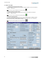
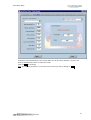
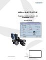
When the communication between PC and drive is set up, the main screen displays some information
regarding rating, limitations and status of the drive (error messages list, status indicators, I/Os status,
speed, position, address on the bus, ...).
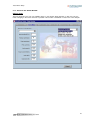
Important note: The number and the description of the information available in the various menus and pages
of the software are depending on the type of the connected drive.
Display example for a CD1-k drive
Chapter 2 – Installation of the software
9
Visual Drive Setup
Status:
A status indicator may group several errors. The detail of these errors is displayed in the error messages
window. Clicking on button R eset will delete the errors stored in the drive, provided that these errors have
been cancelled before. According to the type of the connected drive, the meaning of the status indicators
will be the following:
o
Following error: Dynamic following error (speed or position, according to the drive type).
o
I2t: Motor rms current is higher than the drive rated current.
o
RDC: Counting error (motor with a resolver)
o
Resolver: Resolver cable interrupted.
o
Power stage: One or several errors have occured on the power stage.
o
+24V range: +24V auxiliary supply out of tolerances.
o
Undervolt: No power voltage.
o
C° Motor: Motor temperature too high.
o
EEPROM: Reading and/or writing error in the EEPROM.
o
BUSY: Procedure error.
o
LOW SPEED: Motor speed > low speed threshold (when the pertaining input is activated).
o
BUS ERROR: Communication error on the fieldbus.
o
HES: Hall Effect Sensor error (motor with incremental encoder).
o
°C Drive: Drive temperature too high.
o
Counting: Counting error (motor with encoder).
o
Encoder: Encoder cable interrupted.
Inputs / Outputs:
The status of the hardware inputs and outputs is displayed by indicators.
Limitations:
The drive current rating as well as the parameter set speed and current limitations are displayed in the upper
part of the "drive limitation" window.
Example: CD1-k-230/10.5 shows that the drive type is CD1-k 230 Volts and 10.5 A.
10
Chapter 2 – Installation of the software
Visual Drive Setup
Chapter 3 – Software functions
3.1 - FUNCTIONS
The software functions are the following:
-
Triggering of the auto-phasing procedure.
Triggering of the auto-tuning procedure.
Triggering of the acquisition and cogging torque compensation procedures.
Possibility of manual adjustment of the servo loop gains.
Calculation of the current regulator gains ("C" series drives).
Signal display via the integrated oscilloscope.
Triggering of the parameters saving in the drive EEPROM.
Saving of a drive parameters in a file.
Loading of the parameters of a file in the drive RAM.
Edition of a report containing the drive features and the parameter list.
Selection of a motor in a standard list or entering of a new motor in the user's motor list.
Software speed control of a motor.
Starting of a sequence execution or displacement of the motor shaft until a reference position
(for positioners).
Simulation of the connection with a drive (off-line mode).
Edition of sequence files for positioners.
Chapter 3 – Software functions
11
Visual Drive Setup
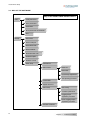
3.2 - MAP OF THE SOFTWARE
Map of the VISUAL DRIVE SETUP software
File
Load parameters
Save parameters
Parameters
Store parameters to EEPROM
Exit
Setup
Disconnect
Select COM port
Select Baud rate
Select address
Disable/Enable CAN
Hardware option
Software control
Drive setup
General info
Servo motor
Motor list
New motor
Current loop adjustment
Auto-phasing procedure
Current limit
Speed reference
Servo loop
Auto-tuning
Controller parameters
Cogging torque
acquisition procedure
Linear cogging torque
acquisition procedure
Encoder resolution
12
Chapter 3 – Software functions
Visual Drive Setup
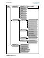
Utilitie
Oscilloscope
Channel
Map of the VISUAL DRIVE
SETUP software
Sample period
Display
Load
Save
Copy
Help
Sequences setup
File
Load sequences from disk
Save sequences to disk
Print report
Save report as ..
Exit
Edit
Copy sequence
Paste sequence
Delete sequence
Delete All sequences
Tools
Compare sequences
Transfer
Load sequences from
Save sequences to drive
Positioner
application setup
General parameters
Movement parameters
Profibus parameters
Input-Ouputs
Scale parameters
Chapter 3 – Software functions
13
Visual Drive Setup
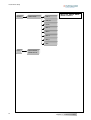
Extras
Offline Mode
CD1-a
Map of the VISUAL DRIVE
SETUP software
CD1-pm
CD1-k
BD1-a
BD1-h
BD1-m
BD1-p
BD2
Info
14
About VISUAL
DRIVE SETUP
Chapter 3 – Software functions
Visual Drive Setup
Chapter 4 – Menus
4.1 - "FILE" MENU
Load parameters
Opens a Windows dialog box which allows to select, in the directories, a file containing parameters
(*.par). The parameters read are displayed and loaded in the drive RAM.
Save parameters
Opens a Windows dialog box which allows to save the current parameters in a file with extension
".par"
Parameters report
Opens a Windows dialog box which allows to save the drive configuration and status as well as the
parameter values in a text file.
Store parameters to EEPROM
The parameters defined during a working session are not automatically stored in the drive EEPROM.
This allows to keep the former parameters before modification when switching on the drive again (and
re-starting the software).
This menu allows to save, in the drive EEPROM, all parameters defined during a working session and
currently stored in the RAM.
Note: This saving is only possible when no error is displayed on the drive and when the drive is
disabled.
Exit
Leaves the software.
4.2 - "SETUP" MENU
Connect (accessible off-line)
Restores the communication between PC and drive.
Note: This menu is also accessible by means of the shortcut button:
For interrupting the communication with the drive, press again this button.
Select Com Port (accessible off-line)
Selection of the PC serial communication port (among COM1 to COM3).
Select Baudrate (accessible off-line)
Selection of the transfer speed on the serial link.
When a drive is connected, the software automatically calculates the communication speed defined in
the drive. But it is possible to modify this value and to store it in the drive. The available values are:
1200, 2400, 4800, 9600 and 19200.
Select Address (accessible off-line)
Selection of the drive serial address. Available values: 0 to 15.
Enable/Disable CAN bus (available for drive types CD1k and BD1h)
Enables or inhibits the CAN bus.
Hardware option
Displays an information screen indicating the version of the drive software as well as the hardware
option.
Software Control (shortcut button :
)
Displays a control screen allowing to run a motor in local mode via the drive. The control screens
may vary according to the drive type (servo drive or positioner).
Chapter 4 – Menus
15
Visual Drive Setup
a/ Non positioning drive
- When option Off is checked, the drive is "disabled".
- When option Analog is checked, the input command taken into account by the drive is the external
input command sent on the CV input. Only the speed information is displayed and updated.
- When option Digital is checked, the input command is sent to the drive via the serial link. In this
case, it is possible to define a reference speed by means of the cursor or by entering directly the
speed value in the window "reference speed" and start the motor in one direction or the other by
means of the "jog" buttons < < and > >. Button 0 stops the motor.
16
Chapter 4 – Menus
Visual Drive Setup
b/ Positioner
- When option Off is checked, the motor is disabled.
- When option On is checked, the motor is enabled.
The brake can be disabled when the motor is enabled, by clicking on button "Disable brake".
Two possibilities are then available to the operator:
1/ Setting a position reference and a speed (by means of the cursor or by entering a value in the
"speed" window) and clicking on G o. The axis position will be displayed and updated during the
rotation until the reference position. The S top button stops the current movement.
2/ Entering a sequence number between 0 and 127. Sequences are movement sequences that are
pre-stored in the drive (see Chapter 7 – Sequences editor). Click on the R un button for starting
the selected sequence. Click on the Stop button for stopping the current sequence.
Setup Window (accessible off-line) – shortcut button:
This menu provides access to the drive parameter setting screens and allows particularly to execute
the automatic loop gains calculation. This section is detailed in Chapter 5 – Drive parameter setting.
When off-line with a drive, this menu provides access to the motor managing screen in the user's
motor list. This function is described in Chapter 5, section 5.4.
Chapter 4 – Menus
17
Visual Drive Setup
4.3 - MENU "UTILITIES"
Digitizing Oscilloscope (accessible off-line)
This menu displays an oscilloscope screen showing the signals acquired in the drive. See details in
Chapter 6 – Oscilloscope.
Note: This menu is also accessible via the shortcut button:
Sequences Setup (accessible off-line)
This menu allows to edit movement sequence files necessary to the positioners. See detail in
Chapter 7 – Sequences editor.
Note: This menu is also accessible via the shortcut button:
Positioner Application Setup
This menu is only accessible for positioners (CD1-p, CD1-pm, BD1/p, BD1/m). It displays a window
that allows the parameter setting specific to these drive types (scale factors, I/Os configuration,
motion parameter setting, Profibus parameter setting, ...).
Note: This menu is also accessible via the shortcut button :
18
Chapter 4 – Menus
Visual Drive Setup
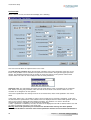
Window "General parameters"
This window allows to define the following parameters:
-
Speed profile: Trapezoidal or S-curve speed profile.
-
Brake on delay: defines the time between the brake release (relay open) and the drive disabling.
-
Brake off delay: defines the time between the drive enabling and the brake disabling (relay
closed).
-
Analog input limitation: Validates the speed reduction option programmed via an analog input.
This parameter is only valid if the analog input option is available. The motion speed is then
limited with regard to the value of the speed programmed inversely proportionally to the analog
input value. This speed reduction is applied to the programmed speed:
- modulation of the programmed speed for positioning sequences (absolute, relative)
- limitation for speed and torque sequences.
When the analog input is equal to 0 V, the motor is running at the programmed speed. With a 5 V
input the motor is running at a speed equal to half of the programmed speed.
-
Analog input reversal: Reverses the sign of the limitation analog input command.
Window "Movement parameters"
This window allows to define the parameters "displacement speed", "acceleration time", "deceleration
time" for a displacement via the JOG+ and JOG- inputs of the drive or for a displacement in the
window "Software control" (see section 4.2 of this chapter).
The parameters "Acceleration time" and "Deceleration time" define the time with regard to the
maximum speed defined by the parameter "Speed limitation" (see chapter 5: "Parameter setting of the
drive").
If the displacement speed is lower than the maximum speed, the trajectory acceleration and
deceleration times will be proportionally smaller.
max. speed
displacement speed
parameter
accel. time parameter
decel. time parameter
Window "Profibus parameters"
This window allows to define the drive Profibus address (for drives using this bus) and to display
information regarding the Profibus communication.
Positioners are delivered with address 126 by default. This address is not an operational one and it
must be modified before getting the bus working.
Indicate the drive address in the "Address" area. When the window is confirmed by clicking on O k ,
save the parameters in the drive EEPROM (see section 4.1 of this chapter), switch off the drive and
switch it on again in order to validate the new address.
The other areas of this window indicate the configuration and the status of the Profibus
communication. For more information, see User manual of the drive.
Chapter 4 – Menus
19
Visual Drive Setup
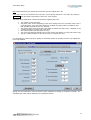
Window "Inputs - Outputs configuration"
This window allows to define the following parameters:
-
Input Hardware/Profibus : This option inhibits the hardware inputs "IN1" to "IN8", "Start" and
"Stop". When the " Profibus" option is selected, the drive does not take into account the value of
these hardware inputs.
-
Inputs polarity: Defines the polarity of the optocoupled inputs. Clicking in the box corresponding
to the signal will switch from 0 to 1 or from 1 to 0. If the box is selected with "1", the input is
active on +24 V.
-
Sequence control: Inputs 1 to 8 (depending on the drive type) can be used for the sequence
selection, provided that the appropriate box is checked. There are maximum 128 sequences that
can be selected this way by these inputs (in all-binary code). The other inputs can be used for
the start condition.
-
Outputs polarity: Defines the polarity of the optocoupled outputs. Clicking in the box
corresponding to the signal will switch from 0 to 1 or from 1 to 0. If the box is selected with "1",
the input is active on +24 V.
-
Output pulse: Outputs 1 to 8 (depending on the drive type) can be defined as pulse outputs if
the appropriate box is checked.
-
Output pulse duration: Pulse duration on the pulse outputs.
-
Minimum SEQ pulse: If this function is activated by checking the box "Minimum SEQ pulse", it
defines the minimum duration of the "Seq" output.
-
InPos window: If this function is activated by checking the box "inPos window", it defines the
position window in which the "Pos" output is activated (only for a positioning). This window is
equal to the arrival position, plus or minus the programmed value. The width of the window is
then twice the programmed value.
-
Digital CAM: If this function is activated by checking the box "Digital CAM", it activates the
"OUT1" output when the motor passes an area defined by positions "Pos1" and "Pos2".
Output OUT1
Motor position
Position P1
Position P2
Window "Scale parameters"
This window allows to define the following parameters:
20
-
Position resolution: Defines the position resolution for one motor revolution, according to the
number of decimals and the required unit. The value range is between 16 and 65536 ppr.
Example: For a resolution of 4 mm/rev., if the number of decimals is 3, the parameters will be:
Resolution: 4000, Decimals: 3, Unit: mm.
-
Decimal number: Number of decimals.
-
Unit: Defines the unit used.
-
Following error threshold: Defines the triggering threshold of the following error.
-
Deadband: Defines the deadband (tolerance) for the position control.
Chapter 4 – Menus
Visual Drive Setup
-
Clear position value: When the box "CLR input enable" is checked, this function allows to use
the "INDEX" input to reset the position counter: the position counter will be reset on the inactiveactive transition of this signal.
-
Reset counter: This function allows to reset the position counter at 0 when it reaches a predefined value. If the value is 0, this function will not be released.
-
Forward: The function "Reset counter" is activated when this box is checked. The motor then
runs in the positive direction during. If the box is not check during an absolute displacement
lower than the value of the "Rest counter" parameter, the motor follows the shortest travel.
-
Soft FC+/-: The "Limit switch" function is only active if the HOME procedure has previously been
executed. The limit switches are inactive for a homing sequence 0. When the motor overshoots
the software limits defined in both fields, it is stopped with a controlled braking which
deceleration is defined by the deceleration parameter, itself defined for the "Jog" function. The
withdrawal out of the limit switches is possible when the function is not active anymore or by a
manual movement (Jog).
4.4 - MENU "EXTRAS"
Offline mode (accessible off-line)
This menu allows to simulate a connection with one of the drives contained in the list, for demo
purposes.
If a drive is already connected to the serial link, cut-off the serial communication by clicking on
before starting the Offline mode on a drive selected in the list. For simulating another drive,
use the same procedure.
In this mode, most of the VDSetup functions are accessible and depending on the simulated drive
type. But the drive configuration is settled and parameters can neither be modified nor saved. The
Offline mode is displayed by the blinking of the "OFFLINE MODE" text in the status bar of the main
VDSetup window.
Click on
Chapter 4 – Menus
for quitting the Offline mode.
21
Visual Drive Setup
4.5 - MENU "INFO"
About VISUAL DRIVE SETUP (accessible off-line)
This menu displays an information window about the software version and copyright, as well as a
warning regarding the parameters of the standard motor list.
22
Chapter 4 – Menus
Visual Drive Setup
Chapter 5 – Parameter setting of a drive
5.1 - INTRODUCTION
The parameter setting of the drive consists in adjusting the drive to the motor and to its load:
speed/current limitation,
loop gains adjustment
calculation of the motor parameters if unknown.
5.2 - START
The parameter setting window can be opened from the Setup menu => Drive Setup, or by clicking on the
"key" icon, in the main window.
⇒ C ancel button
For all note book tabs of this parameter setting window, clicking on this button will lead back to the note book
tab "General info." without saving the modifications made in the current note book tab. Clicking on the
C ancel button in the note book tab "General info." closes the parameter setting window.
⇒ O k button
This button allows to come back to the display of the note book tab "General info." while saving the
modifications made in the current note book tab. But, if the modification of a parameter appears to be not
valid, a warning message regarding this parameter will be displayed and the modifications made in this note
book tab will not be saved.
⇒ S tart Wizard button
This button starts the wizard of the drive parameter setting. This procedure is described in section 5.5 of this
chapter.
Important note
As soon as a note book tab of the parameter setting screen is selected, all other note book tabs are not
accessible anymore as long as the operator has not clicked on O k or on C ancel .
Chapter 5 – Parameter setting of a drive
23
Visual Drive Setup
5.3 - NOTE BOOK TABS OF THE PARAMETER SETTING WINDOW
5.3.1 - Note book tab "GENERAL INFO."
This window contains several frames. Each of them contains a summary of the information mentioned on the
appropriate note book tab.
For acceding to the motor parameter setting note book tab, click on S elect Motor in the frame "Servo Motor"
or click directly on the note book tab "Servo Motor".
For acceding to the note book tab of the current parameter setting, click on M odify in the frame "Current
Limit" or click directly on the note book tab "Current Limit".
For acceding to the note book tab of the speed parameter setting, click on M odify in the frame "Speed Limit"
or click directly on the note book tab "Speed Limit".
For acceding to the filters and loop gains note book tab, click on A uto-tuning in the frame "Servo Loop" or
click directly on the note book tab "Servo Loop".
For acceding to the note book tab of the sensor parameter setting, click on M odify in the frame "Encoder
Output" or click directly on the note book tab "Encoder Output".
The button O ffset Compensation allows to start an automatic procedure for the offset compensation of the
analog input command on the CV input, for speed drives with analog input command.
Buttons + and – of the frame "Servo Loop" increase or decrease the servo loop stability gain.
24
Chapter 5 – Parameter setting of a drive
Visual Drive Setup
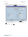
5.3.2 - Note book tab "SERVO MOTOR"
Off-line mode
This note book tab is the only one available off-line, in the window "Setup Window". In this case, only the
motor managing in the user's motor list is possible. This function is described in section 5.4 of this chapter.
Chapter 5 – Parameter setting of a drive
25
Visual Drive Setup
On-line mode
When a drive is on line, the note book tab display is the following:
This note book tab allows to adjust the drive to the motor.
The auto-phasing procedure allows the automatic calculation of the motor parameters if they are not yet
known. This procedure can be selected in the pull-down menu located in the right hand upper part of the
window. The identified parameters are the number of motor pole pairs, the motor phases order and the
resolver offset. The user can then modify the value of these parameters.
Importante note: The auto-phasing procedure must be used with the motor uncoupled from its mechanical
load. Before executing this procedure, make sure that the motor shaft is free and its rotation over one
revolution is not dangerous for the operator.
If the motor specifications are already stored in the connected drive, these will be updated in the various
fields.
In the frame "Motor List", it is possible to select a motor contained in a previously created list. In this case,
the manufacturer's specifications of the selected motor are displayed and the various fields updated. There is
then no more need for starting the auto-phasing procedure. The selection of a motor in the list will
automatically start the calculation of the current loop parameters.
If, later, a parameter is modified by the user, the name of the displayed motor will be deleted and the user will
get asked for defining and saving a new motor type.
Warning: Some motor parameters pre-recorded in the standard motor list may have been updated.
It is therefore advisable to check the value of these parameters with the concerned motor manufacturers.
26
Chapter 5 – Parameter setting of a drive
Visual Drive Setup
Note: Motors defined by the operator and saved in the list are marked with a "U".
If the motor used is not contained in the motor list, it can be directly defined as a new motor by clicking on
n ew motor . This procedure is described in section 5.4 of this chapter.
The frame "Motor Parameters" contains all information regarding the motor:
The number of motor pole pairs
The phase order, which is depending on the motor winding and on the connection order of the U,
V and W phases. If the connection diagram is modified, the phases order is modified as well.
Both possible permutations are 120° and 240°.
The resolver offset is the phase shift value between resolver and motor rotor. It depends on the
mechanical resolver mounting and of the wiring.
The motor thermal sensor type (CTN or CTP).
The motor temperature threshold values for the warning and release of a fault (CD1-k drive only).
The gain values calculated for the current loop ("C" series drives only).
For calculating the current loop gains, display the calculation window by selecting "Current Loop Adjustment"
in the right hand list:
Specify the motor inductance value and start the gains calculation by clicking on the button "Calculate". The
calculated gain values will be displayed in the appropriate frames.
Chapter 5 – Parameter setting of a drive
27
Visual Drive Setup
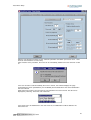
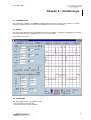
5.3.3 - Note book tab "CURRENT LIMIT"
This note book tab informs the user about the drive current/voltage ratings and allows to define the current
limitation specifications:
- The drive rated current limitation mode is selected in the I2t mode frame:
In "fusing" mode, the drive is disabled when the current limitation threshold is reached.
In "limiting" mode, the current is only limited at the value defined by the "rated current"
parameter, when the limitation threshold is reached.
- Selection of the maximum current (in % of the drive current rating):
This parameter defines the maximum current provided by the drive.
It can vary between 20 % and 100 % of the drive current rating value.
This parameter is defined according to the specifications of the motor and drive used.
- Selection of the rated current (in % of the drive current rating):
This parameter defines the rated current provided by the drive (threshold of the drive I2t
protection). It can vary between 20 % and 50 % of the drive current rating value.
This parameter is defined according to the specifications of the motor and drive used.
- Selection of the I2t protection mode
28
Chapter 5 – Parameter setting of a drive
Visual Drive Setup
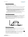
a/ Current limitation in "fusing" mode
If the RMS current has not dropped below 85 % of the rated current after 1 second, the I2t fault is released
and the drive is disabled.
When the drive RMS current (I2t) reaches the Rated current value, the I2t protection limits the drive output
current at this value.
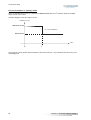
Limitation diagram of the drive output current in an extreme case (motor overload or shaft locked):
Amplifier current
Maximum current
t2 = current limitation
t3 = I2t protection
Rated current
Time
t0
t2
t3
The maximum current duration before limitation at the rated current is depending on the value of the Rated
current and Maximum current parameters.
T max (second) = t2 - t0 = 4. [Rated current (%)]2 / [Maximum current (%)]2
The current limitation duration before the release of the protection is depending on the value of the Rated
current and Maximum current parameters:
Tlim (second) = (t3 - t2) = 1 - 0,7 . [Rated current (%)]2 / [Maximum current (%)]2
NOTES:
These formula are still correct for a Maximum current / Rated current ratio > 1.5.
When the Maximum current / Rated current ratio = 1, there is no interruption and the current is maintained
at the rated current value.
The I2t signal can be displayed by means of the digitizing oscilloscope (see Chapter 6).
Chapter 5 – Parameter setting of a drive
29
Visual Drive Setup
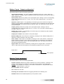
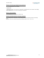
b/ Current limitation in "limiting" mode
When the amplifier RMS current (I2t) reaches the Rated current value, the I2t protection limits the amplifier
output current at this value.
Limitation diagram of the drive output current:
Amplifier current
Maximum current
t2 = current limitation
Rated current
Time
t0
t2
The maximum current duration before limitation at the rated current (t2 - t0) is calculated the same way as for
the Fusing mode.
30
Chapter 5 – Parameter setting of a drive
Visual Drive Setup
5.3.4 - Note book tab "SPEED LIMIT"
The following parameters can be adjusted according to the drive type:
Reverse movement: This function allows to reverse the motor rotation direction with regard to the same
speed input command. The counting direction with regard to the motor rotation direction remains unchanged
for the encoder output.
Rated speed (rpm): This parameter defines the motor rated speed (in rpm), which corresponds to an input
command voltage defined in the frame "Reference voltage". The maximum speed corresponds to an input
command voltage of 10 V.
The maximum speed corresponds to a maximum motor speed for an input command voltage of 10 V. It is
between 100 rpm et 14000 rpm according to the motor type used and is automatically calculated from the
rated speed value.
Accel/Decel Time (s): This parameter defines the motor acceleration or deceleration time corresponding to
the maximum speed previously defined. It is calculated by the drive during the auto-tuning procedure in order
to get an acceleration equal to 0,8 Imax. It can then be modified by the user. The adjustment range is
between 1ms and 1s and the maximum possible value of the acceleration/deceleration ramp is 3600 rpm/s.
Reference voltage: Input command voltage corresponding to the motor rated speed for drives with analog
speed input command.
Chapter 5 – Parameter setting of a drive
31
Visual Drive Setup
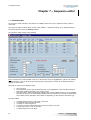
5.3.5 - Note book tab "ENCODER OUTPUT"
This note book tab allows to modify the encoder output resolution and to re-programme it.
CD1-a drive:
The Division ratio of the encoder output allows to adjust the number of ppr:
Division ratio
1
2
4
8
Number of ppr
1024
512
256
128
"B" series drives:
The maximum encoder resolution is depending on the maximum speed of the application:
Maximum speed
900 rpm
3600 rpm
14400 rpm
Maximum encoder resolution
8192
4096
1024
Minimum width of the marker pulse
1
2
8
If the maximum speed is defined after the encoder output programmation, it may not be compliant.
The parameter Number of zero pulses defines the number of zero pulses on channel Z for one motor
revolution. The adjustment range is between 1 and 16.
32
Chapter 5 – Parameter setting of a drive
Visual Drive Setup
The parameter Zero pulse shift defines the shift between the first zero pulse on channel Z and the reference
zero position of the resolver. The adjustment range is between 0 and 32767. The value 32768 corresponds to
one motor revolution.
The parameter Zero pulse width defines the zero pulse width on channel Z. The adjustment range is between
the minimum width (see table above) and 32767. The value 32768 corresponds to one motor revolution.
The button O k saves the modifications of the encoder output according to the parameters above.
Chapter 5 – Parameter setting of a drive
33
Visual Drive Setup
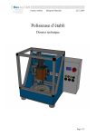
5.3.6 - Note book tab "SERVO LOOP"
5.3.6.1 - AUTO-TUNING PROCEDURE
The note book tab "Servo Loop" allows to calculate and adjust the regulator parameters.
The "auto-tuning" frame allows the user to select the regulator type, the filter and bandwidth types as well as
the time interval for the speed measurement.
Clicking on O k starts the execution of the auto-tuning procedure which will take into account these
selections for the identification of the regulator gain parameters.
Selection of the regulator type:
"P" type: This mode corresponds to the motor speed control, with a traditional regulator (proportional).
"PI" type: This mode corresponds to the motor speed control, with a traditional regulator (proportional +
integral).
"PI2" type: This mode corresponds to the motor speed control with a proportional regulator + two integral
terms. The use of the second integral term allows to increase the axes stiffness and the regulation accuracy
at very low speed.
"Position" type: The drive works in position mode (input = position input command). This mode is only
available for drives with a position loop.
Important note:
When the "position" mode is selected, the auto-tuning procedure will automatically calculate the speed and
position loop gains. But, if one of the speed modes (P, PI or PI2) is selected, the auto-tuning procedure will
only calculate the speed loop gains.
34
Chapter 5 – Parameter setting of a drive
Visual Drive Setup
Selection of the filter type integrated in the speed loop:
One of the following filters can be selected:
- Standard filter.
- Antiresonance filter: To be used for the compensation of backlashes due to the mechanics and couplings.
- Max. stiffness filter: To be used for increasing the axis stiffness.
Selection of the bandwidth:
Three bandwidth types are available: low, medium, high.
Selection of the time interval for the speed calculation:
When checking the box "auto-select", the auto-tuning procedure will automatically calculate the sampling
period.
Otherwise, a time can be selected among the three following values: 0.5 ms, 1 ms or 2 ms.
Chapter 5 – Parameter setting of a drive
35
Visual Drive Setup
5.3.6.2 - COGGING TORQUE COMPENSATION AND PARAMETER SETTING OF THE FOLLOWING ERROR
The cogging torque of brushless permanent magnet motors is due to the interaction between the
rotor magnets and the stator teeth. On some drive types, this cogging torque can be compensated.
Before starting the compensation procedure, check that the motor is uncoupled from its load and can
run at least over two revolutions in both directions without danger for the operator. The procedure is
started by selecting "Cogging torque acquisition procedure" in the list.
Selecting "Linear cogging torque acquisition procedure" will start the procedure for linear motors.
When the cogging torque acquisition is made, the torque compensation can then be activated or
desactivated by checking or checking out the box "enable cogging torque compensation".
Following error:
The user can define a triggering threshold of the following error, corresponding to the difference read
between the input command and the speed: select a value between 0 and 25000 rpm in the
appropriate field.
Other adjustments:
For series CD1-k drives, this screen also allows the parameter setting of the CAN bus cycle time and
of the position resolution.
36
Chapter 5 – Parameter setting of a drive
Visual Drive Setup
5.3.6.3 - Regulator parameters
This screen allows to modify, in real time, the parameters calculated by the auto-tuning function.
Servo loop stability:
The buttons + and – allow to increase or decrease the stability gain of the servo loop.
Sampling period:
The value of the time interval between two position measurements can be modified for the speed calculation.
The three available values are: 0.5 ms, 1 ms or 2 ms.
Regulator gain values:
If the connected drive has got a position loop, the gain values of the speed and position loops will be
displayed on the screen. Otherwise, only the speed loop gains will be available.
Any modification of these gains will immediately be taken into account by the drive.
Important notes:
A gain value can be modified by entering directly the value in the appropriate frame or by using the
appropriate cursor but, in that case, only a modification of +/- 20 % will be possible at each motion of the
cursor.
When a value is modified by the cursors, it is immediately sent to the drive. On the contrary, if a value is
entered in one of the fields, it will only be sent to the drive by clicking on O k .
The R efresh button allows to read again, at any time, the values stored in the drive.
The C lose button allows to come back to the note book tab "General info."
Chapter 5 – Parameter setting of a drive
37
Visual Drive Setup
Filters:
38
Analog input low-pass filter: This parameter defines at - 3dB the cut-off frequence of the digital
first order filter acting on the analog speed input command. The default value is set at 1000 Hz.
Speed error low-pass filter: This parameter defines at - 3 dB the cut-off frequency of the digital
filter acting on the speed regulator output.
Antiresonance filter: Third order filter which purpose is to compensate the backlashes due to
the mechanics and couplings.
Chapter 5 – Parameter setting of a drive
Visual Drive Setup
5.4 - CREATION AND MANAGING OF A NEW MOTOR
The VDSetup software contains a list of standard motors which parameters are already defined. But the user
can also define specifications for a new motor and save them in a user motor list. The names of these motors
will automatically be marked with a "U".
The user motor list can be managed off-line and on-line.
5.4.1 - OFF-LINE MODE
In this mode, the user can accede to the user motor list by selecting the Setup menu in the Setup
window or by clicking on the pertaining shortcut button.
Note: The displayed note book tab "Servo Motor" is the only one accessible off-line.
The pull-down menu allows to select:
the display of the user motor list,
the creation of a new motor,
the specifications modification of an already defined user motor,
the deletion of a motor from the list.
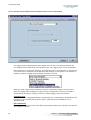
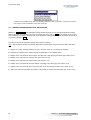
The creation procedure of a new motor is the following:
1/ Select "Add a motor to the list".
Chapter 5 – Parameter setting of a drive
39
Visual Drive Setup
2/ Select the motor type in the list and click on N ext .
40
Chapter 5 – Parameter setting of a drive
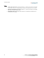
Visual Drive Setup
3/ Enter the motor specifications in the various fields. Give an ID number between 0 and 551 and
enter the manufacturer's name as well as the model.
Click on N ext for confirming.
Note: The definition procedure of a new motor can be left at any time by clicking on Q uit .
Chapter 5 – Parameter setting of a drive
41
Visual Drive Setup
4/ Specify the number of pole pairs, the phase order, the thermal sensor type. The frame on the right
hand side concerns the sensor type. The pertaining fields to be filled in are then depending on the
selected motor type.
Confirm by clicking on O k .
The new motor is now included in the user motor list. A message will inform the user that he can now
enter another motor, if wanted.
The user motor list can then be displayed by selecting the function "Show the user motors list":
Display of the list:
It is also possible to modify the parameters of a user motor or delete a user motor from the list by
selecting respectively "Modify motor parameters" or "Delete a motor from the list" and then selecting
the motor to be modified or deleted from the list.
Note: The modification or deletion of a motor from the user motor list is only possible off-line.
42
Chapter 5 – Parameter setting of a drive
Visual Drive Setup
5.4.2 - ON-LINE MODE
In this mode, the user can accede to the user motor list by selecting the note book tab "Servo
Motor" in the "Setup Window", by clicking on N ew Motor .
Enter the thermal sensor type and the motor inductance value. Click on C alculate : the software will
calculate and display the current loop gains.
Note: It is possible to leave the definition procedure of a new user motor at any time by clicking on
Q uit .
Confirm the entered data by clicking on N ext .
Chapter 5 – Parameter setting of a drive
43
Visual Drive Setup
Define the ratings and the current limitation mode (see section 5.3.3 - Note book tab "current limit").
Confirm by clicking on N ext .
44
Chapter 5 – Parameter setting of a drive
Visual Drive Setup
Start the auto-phasing procedure for the automatic parameter calculation (see section 5.3.2 - Note
book tab "Servo Motor in on-line mode").
After execution of the procedure, the motor can be immediately added to the user motor list or later
on.
If the user chooses to add immediately the motor to the list, the software displays the page
summarizing the motor specifications (non modifiable) and the fields where the motor identification
has been entered.
Enter this ID and confirm. The new motor is now included in the user motor list. This list can be
displayed by selecting "Show the user motors list":
If the motor has to be added later to the user motor list, an additional line will be added to the
instructions list:
Chapter 5 – Parameter setting of a drive
45
Visual Drive Setup
It will then be possible, at any time, by selecting "Add new motor in user list", to enter the ID of the
new motor in order to include it in the user motor list.
5.5 - "GUIDED PARAMETER SETTING" PROCEDURE
Clicking on S tart wizard of the parameter setting window will guide the user through all parameter setting
steps of the drive. For switching over from one step to the other, click on N ext , at the bottom of the screen.
This will display the various note book tabs of the parameter setting window. But this procedure can be left at
any time by clicking on Q uit .
The various steps of the parameter setting wizard are the following:
Note : See mentioned sections for detailed explanations regarding the various parameter setting note book
tabs.
1 - Display of a safety message inviting the user to stop the motor for a control by the software.
2 - Request for activation of the "Enable signal" or desativation of the "Inhibit" signal.
3 - Display of the note book tab "Servo Motor" and start of the auto-phasing procedure (see section 5.3.2)
4 - Display of the note book tab "Current Limit" (see section 5.3.3)
5 - Display of the note book tab "Speed Limit" (see section 5.3.4)
6 - Display of the note book tab "Encoder Output" according to the drive type (see section 5.3.5)
7 - Display of the note book tab "Servo loop" and start of the auto-tuning procedure (see section 5.3.6)
8 - Start of the offset compensation procedure for drives with an analog command input (see section 5.3.1)
46
Chapter 5 – Parameter setting of a drive
Visual Drive Setup
Chapter 6 – Oscilloscope
6.1 - INTRODUCTION
The oscilloscope available in the VDSetup software allows the real time control of the evolution of a certain
number of signals acquired in the drive and transmitted to the PC via the serial link.
6.2 - START
The oscilloscope window can be opened either from the menu Utilities => Digitizing oscilloscope or by clicking
on the icon representing an oscilloscope screen, in the main window.
Main oscilloscope screen:
6.3 - FUNCTIONS
The oscilloscope has got two operation modes:
- drive connected to the serial link
- drive disconnected from the serial link.
Chapter 6 – Oscilloscope
47
Visual Drive Setup
If no drive is connected, the oscilloscope is starting in "off-line" mode. In this mode, only the curves
previously saved on the disk (files *.osc) can be displayed and printed.
6.4 - STEP BY STEP SIGNAL ACQUISITION
If a drive is connected, the names of the latest signals saved in the drive are displayed by default in the main
window.
The signals to be acquired are selected in the channel selection window accessible by a click on C hannel in
the main window.
The signals that can be displayed are the following:
Signal
Speed
Speed ref
Imes
Idc
Iq
Id
Resolver
Pos error
I flux ref
I flux mes
I2 t
DC bus
Threshold
Unit
rpm
rpm
% Imax
% Imax
% Imax
% Imax
pts
encoder edges
% Imax
% Imax
% Imax.S
volts
pts
Description
Speed measurement
Speed input command
Current measurement
Current input command
Quadrature current measurement
Direct current measurement
Position given by the resolver
Position error
Magnetization current input command
Magnetization current measurement
Current consumption measurement
DC bus voltage measurement
Dynamic following threshold
Up to three signals can be selected this way in the "Channel" window.
For each signal to be acquired, select a scale among the various possible values (0.05, 0.1, 0.2, 0.5, 1, 2, 5,
10, 20, 50, 100, 200, 500, 1000, 2000, 5000, 10000).
An offset can be applied to the signal or the signal can be reversed.
Confirm the information of the "Channel" window by O K. The selected signals are now displayed in the main
window.
48
Chapter 6 – Oscilloscope
Visual Drive Setup
Note: A signal display can be switched on "Off" by checking the pertaining box in the main window. But the
acquisition of this signal will be made by the drive just the same. If the signal has not to be acquired by the
drive, "Off" must be selected in the "Channel" window.
The next step consists in adjusting the time base. Click on S ample for displaying the window below:
The various possible "Sample period" values are:
-
0.5 ms
1 ms
2 ms
4 ms
5 ms
10 ms
20 ms
40 ms
50 ms
100 ms
200 ms
400 ms
500 ms
1s
2s
Enter the triggering reference (left, right or centered) and, possibly, a triggering time in ms.
Confirm these information by O k . The time base value is now displayed in the main window.
Adjust now the triggering mode by clicking on t rigger mode .
It can be triggered on a rising edge, a falling edge, a high level, a low level or on an error.
Confirm by O k .
Chapter 6 – Oscilloscope
49
Visual Drive Setup
Then, for adjusting the triggering level, display the line on the screen by clicking on the box "Trigger On/Off"
and adjust the level ( t rig level button). The triggering level value is displayed at the bottom of the screen, on
the right hand side.
The display can be modified in the display options window by clicking on D isplay .
This window allows the selection of a display on 2 screens (useful for the acquisition of 3 signals).
If two screens are selected, the signals of channels 1 and 2 are displayed on screen 1 and the signal of
channel 3 is displayed on screen 2.
The signals can be displayed on a white screen (for ink saving when printing).
It is also possible to select the axes type and the curves as dotted or continuous lines.
Confirm the display options by O k .
The curve colour can be modified by C hn Color for displaying a colour selection window.
Note: Some colours are defined by default. If a curve does not appear on the screen, check that its colour is
not the same as the screen colour.
The curves acquisition is started by T rigger . During the signal acquisition by the drive, the LED is lit in red.
It becomes green when the acquisition is over. If the LED remains red, modify the triggering type or level until
you get the acquisition.
Once the acquisition over in the drive, download the curves via the serial link by clicking on T ransfer .
When the curves are displayed, their offset and colour can still be modified and they can still be reversed or
switched on "Off" as well.
CAUTION: Confirming a new signal in the "Channel" window will delete the current signals.
6.5 - OPERATIONS ON THE DISPLAYED CURVES
6.5.1 - Measurements
Four cursors are available for level or time measurements on the displayed curves: T1 and T2 for time
measurements, V1 and V2 for level measurements. The cursors are displayed if their pertaining boxes are
checked.
For modifying a cursor position, the cursor must first be selected (option button beside the box to be
checked). Then click on the curve display screen, on the place where the cursor must be placed.
Note: The "dt" field corresponds to the time difference measured between cursors T1 and T2. This value can
only be updated when both cursors are displayed.
Use the "Set" button for assigning the level measurement cursors to the displayed curves.
50
Chapter 6 – Oscilloscope
Visual Drive Setup
Note: The "dv" field corresponds to the level difference measured between cursors V1 and V2, provided that
both cursors have been assigned to the same curve.
6.5.2 - The zooms
Use the keys Z oom+ and Z oom- for enlarging or reducing the curves width. The zoom is centered on the
position of the T1 cursor (whatever displayed or not). For zooming a specific area of the curve, drag at first
the cursor on this area. The scroll keys allow to display the complete curves when they are enlarged.
6.6 - LOADING OF A FILE
For the display of signals previously saved in a file, click on L oad in the main screen and select the desired
file. The curves recording files have got the extension ".osc".
6.7 - SAVING IN A FILE
For saving the curves in a file, click on S ave in the main screen, select the destination directory and name
the file. The ".osc" extension will be automatically added to the file name.
6.8 - COPY IN THE CLIPBOARD
For copying the curves in the clipboard, click on C opy in the main screen and select the screen(s) to be
copied.
The copy is made in the Windows® clipboard in order to be included in a document or printed. The signal
names, their scale and the time base will be added to the curves in superposition.
Chapter 6 – Oscilloscope
51
Visual Drive Setup
Chapter 7 – Sequence editor
7.1 - INTRODUCTION
The sequence editor included in the software is available off-line and only for positioners when a drive is
connected.
The sequence editor is started either via the menu "Utilities => Sequences Setup" or by clicking directly on
the shortcut button in the main VDSetup window.
The sequence editor window is the following:
Note: The sequence currently edited is the one of the first line of the list (highlighted in yellow). For editing a
special sequence, move in the list by the horizontal arrow keys until the number of the desired sequence
appears on the first line.
The editor is made of three different areas:
The menu area,
The upper area which is the sequences list that can be pulled down. This area also includes a
legend bar updated according to the sequence type.
The lower area in which the parameter setting of the currently edited sequence can be modified.
The fields of this area are automatically updated when the sequences of the list are pulled down.
The number and the description of the fields are depending on the sequence movement type.
The editor allows:
52
to
to
to
to
to
to
upload sequence files (.seq) saved on the disk,
download sequences from the drive,
modify or create sequences,
compare currently edited sequences with those saved in the drive,
save sequences in a file on the disk,
upload sequences in the drive,
Chapter 7 – Sequence editor
Visual Drive Setup
to print a report listing all sequences,
to save a file in text format listing all sequences.
7.2 - "FILE" MENU
Load sequences from disk
Opens a Windows® dialog box allowing the selection, in the directories, of a file containing
sequences (*.seq). The decoded sequences are displayed in the editor.
Save sequences to disk
Opens a Windows® dialog box allowing to save the currently edited sequences in a file with extension
".seq"
Print report
Opens a Windows® dialog box allowing to print a report of the sequences currently edited.
Save report as
Opens a Windows® dialog box allowing to save a report of the sequences currently edited in a text
format file.
Exit
Closes the sequence editor.
7.3 - "EDIT" MENU
Copy sequence
For copying a sequence, pull down the sequences until the sequence to be copied is displayed on
the first line. Then select "Copy sequence" or enter C trl + c . The sequence to be copied is stored
in a buffer.
Paste sequence
For pasting a sequence, pull down the sequences until the required sequence displayed on the first
line. Then select "Paste sequence" or enter C trl + v . The sequence is pasted.
Delete sequence
For deleting a sequence, pull down the sequences until the sequence to be deleted is displayed on
the first line. Then select "Delete sequence" or enter C trl + w . After confirmation, the sequence is
deleted.
Delete all sequences
For deleting all sequences, select "Delete all sequences" or enter C trl + x . After confirmation, all
currently edited sequences are deleted.
CAUTION: Only the edited sequences are deleted but the sequences stored in the drive remain
unchanged.
7.4 - "TOOLS" MENU
Compare sequences
This function allows to compare the parameters of the currently edited sequences with those of the
sequences stored in the drive. If a difference is found, a message displays the number of the first
sequence having different parameters.
7.5 - "TRANSFER" MENU
Load sequences from drive
This function allows to load in the editor the sequences pre-recorded in the drive, if a drive is
actually connected.
Send sequences to drive
This function allows to save the currently edited sequences in the drive, if a drive is actually
connected.
Chapter 7 – Sequence editor
53
Visual Drive Setup
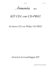
7.6 - EDITION OF A SEQUENCE
Each programmed sequence can be:
an absolute displacement,
a relative displacement,
a homing,
a speed profile,
a torque sequence (speed profile with current limitation).
The movement type is selected in the "Movement type" list of the edition area. As soon as a movement has
been selected, the various parameters to be initialised for this movement type are displayed in the editor.
Possible parameters of a sequence:
Movement type
Defines the movement type:
Absolute: Absolute positioning.
Relative: Relative positioning.
Home: Searching procedure of the axis home position.
Speed: Speed profile.
Torque: Speed profile with current limitation.
Position
Position to be reached in absolute or relative mode according to the motion type.
Speed
Defines the motion speed in rpm.
Acceleration
Defines the acceleration ramp in ms.
Deceleration
Defines the deceleration ramp in ms.
Delay ou Time out
Defines, in ms, the time delay at the end of the positioning.
Next sequence
Defines the sequence to be executed after the current one.
Counter
Defines how many times the sequence must be executed.
Counter link
Defines the number of the sequence to be executed if the counter is not set at zero.
Output
Defines the possible action on the outputs.
Output trigger
Defines the triggering moment on the outputs.
Output position
Defines the outputs triggering position.
Torque
Defines the torque input command in percentage of the maximum current.
Start condition
Defines the sequence triggering condition from the logic inputs defined as start condition.
Note:
For a detailed description of the parameter programmation of a sequence, see user manual of the drive used.
When all parameters are initialised, click on V alidate to confirm the sequence and display it in the list. A
coherence control of these parameters is made in order to check that they are actually in their variation
range.
The C ancel button cancels all edition modifications if the sequence has not been yet confirmed.
54
Chapter 7 – Sequence editor