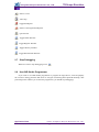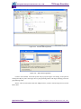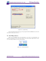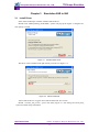
1
TKScope Emulator for AVR User Manual Application Note AN05220023 V1.02 Date: 2011/02/10 Application Note Categories Content Keywords TKScope AVR IAR AVR Studio Summary TKScope Emulator for AVR User Manual Guangzhou Zhiyuan Electronics CO., LTD. Guangzhou Zhiyuan Electronics CO., LTD. TKScope Emulator TKScope Emulator For AVR User Guide The revision of history Version Date Reason V1.00 2009/09/03 Create a document V1.01 2010/08/11 Support All 8bit AVR Device V1.02 2011/02/10 Support JTAG Chain Application Note Date: 2011/02/10 ©2011 Guangzhou Zhiyuan Electronics CO., LTD. i Rev 1.02 TKScope Emulator Guangzhou Zhiyuan Electronics CO., LTD. TKScope Emulator For AVR User Guide Table of Contents Chapter 1 TKScope Emulator Introduction ...................................................................1 1.1 1.2 1.3 1.4 AVR Emulator Support Devices................................................................................1 AVR Emulator Feature ..............................................................................................2 AVR Emulator Support IDE Environment ................................................................2 Connect with TKScope .............................................................................................3 Chapter 2 Simulation AVR in AVR Studio ....................................................................5 2.1 2.2 2.3 2.4 2.5 2.6 2.7 2.8 2.9 Install Driver .............................................................................................................5 Install USB Driver.....................................................................................................7 Install JTAGICEmkII driver......................................................................................9 Start Debugging ...................................................................................................... 11 Setting Emulator Parameter ....................................................................................13 Debug Tools ............................................................................................................16 Stop Debugging.......................................................................................................17 Use AVR Studio Programmer..................................................................................17 Exit TKScpe Service ...............................................................................................19 Chapter 3 Simulation AVR in IAR...............................................................................20 3.1 3.2 3.3 3.4 Install Driver ...........................................................................................................20 Install USB Driver...................................................................................................22 Add Driver File .......................................................................................................22 Emulator Parameter Setup.......................................................................................26 3.4.1 Harware Select ....................................................................................................26 3.4.2 Main Options.......................................................................................................26 3.4.3 Aux options .........................................................................................................28 3.4.4 TAP cofig ............................................................................................................28 3.4.5 Prog optoins ........................................................................................................29 3.4.6 TKScope doctor ..................................................................................................31 3.5 Debug ......................................................................................................................31 3.5.1 Debug Tools ........................................................................................................32 3.5.2 Stop Debug..........................................................................................................34 Application Note ©2011 Guangzhou Zhiyuan Electronics CO., LTD. Date: 2010/02/10 Rev 1.02 Guangzhou Zhiyuan Electronics CO., LTD. TKScope Emulator TKScope Emulator For AVR User Guide Chapter 1 TKScope Emulator Introduction 1.1 AVR Emulator Support Devices TKScope emulator able to support AVR core simulation models are summarized as follows: K Series: K8 / K9; DK Series: DK9 / DK10. AVR emulator support AVR emulate Atmel AVR device which has JTAG port and all device ISP, the emulator suppor the device as follows: ATmega16,ATmega16A,ATmega162 ATmega165,ATmega165P,ATmega165PA ATmega169,ATmega169P,ATmega169PA ATmega32,ATmega32A,ATmega323 ATmega325,ATmega325P,ATmega3250,ATmega3250P ATmega329,ATmega329P,ATmega329PA,ATmega3290,ATmega3290P ATmega64,ATmega64A,ATmega644 ATmega645,ATmega6450,ATmega649,ATmega6490 ATmega640,ATmega1280,ATmega1281,ATmega2560,ATmega2561 ATmega128,ATmega128A, ATmega164P,ATmega164PA,ATmega324P,ATmega324PA,ATmega644P,ATmega644PA ,ATmega1284P AT90CAN32,AT90CAN64,AT90CAN128 AT90USB646,AT90USB647,AT90USB1286,AT90USB1287 ATmega48,ATmega48A,ATmega88,ATmega88A,ATmega168,ATmega168A ATtiny13,ATtiny13A ATtiny2313,ATtiny2313A,ATtiny4313 ATtiny25,ATtiny45,ATtiny85 ATtiny24,ATtiny24A,ATtiny44,ATtiny44A,ATtiny84,ATtiny84A ATtiny261,ATtiny261A,ATtiny461,ATtiny461A, ATtiny861,ATtiny861A ATtiny87,ATtiny167 AT90PWM2,AT90PWM2B,AT90PWM216 AT90PWM3,AT90PWM3B,AT90PWM316 AT90USB82,AT90USB162 ATxmega64A1,ATxmega128A1, ATxmega64A3, ATxmega128A3,ATxmega192A3,ATxmega256A3 ATxmega256A3B, ATxmega16A4,ATxmega32A4, ATxmega16D4,ATxmega32D4, ATxmega64D3,ATxmega128D3,ATxmega192D3,ATxmega256D3 More devices will be support in the near future. TKScope emulate AVR device use the POD is: POD-JTAG-AVR-P10. Application Note Date: 2011/02/10 ©2011 Guangzhou Zhiyuan Electronics CO., LTD. 1 Rev 1.02 TKScope Emulator Guangzhou Zhiyuan Electronics CO., LTD. TKScope Emulator For AVR User Guide Figure 1.1 POD-JTAG-AVR-P10 1.2 AVR Emulator Feature TKScope AVR emulator feature: USB2.0(High Speed)communication interface,fast prommning speed,save your developing time; JTAG programming speed is ATMEL’s JTAGICE mkII 2.8 times; ISP(1MHz clock)speed is ATMEL’s JTAGICEmkII 4.7 times; Support K-Flash programming software,support fast speed promming; Support programming Flash、EEPROM、Fuse、LockBits; Support all MEGA device JTAG programming and debuge; Support all debugWIRE device debug; Support ISP programming; Support XMEGA device PDI programming and debuge; Auto detect AVR Studio Version,you can use all AVR Studio Version did NOT need change driver; Support High level language and assembler language debuge; Support data break point and no limit flash break point; Support dynamic break point, you can set and clear break poit when the target is running; Support code modify, Make you debuge more convenient; Hardware selftest; 1.3 Code and data cache, improve the debugging performace; Emulator can follow the target device volatage. AVR Emulator Support IDE Environment TKScope simuation AVR device support multiple IDE environment, Engineers can be Choose the familiar IDE, support the IDE as follows: TKStudio, Zhiyuan company, Chinese/english environment, multi-core compiling /debugging, powerful built-in editor AVR Studio, Atmel Corp., English environment, Can be plug-in GCC comlier. IAR, IAR Corp, Engish, multi-core compiling/debugging. Application Note Date: 2011/02/10 ©2011 Guangzhou Zhiyuan Electronics CO., LTD. 2 Rev 1.02 TKScope Emulator Guangzhou Zhiyuan Electronics CO., LTD. TKScope Emulator For AVR User Guide Figure 1.2 Support IDE Environment 1.4 Connect with TKScope POD_JAG_AVR_P10 has 2 ports,40P connect to Emulator’s JP4,10P connect to your target (JTAG interface). ADP_AVR_P10_P6 use in ISP proggrame and debugWIER simulation(support in the near future), Connect the J3(10P) to POD_JTAG_AVR_P10,and J4 connect to your target. JTAG and ISP interface the same as Atmel’s define, as Figure 1.3. Figure 1.3 JTAG & ISP Interface We suggest use the 6PIN ISP connects when you use the debugWIRE simulation. Notice: the Adaptor RESET pint connects to TMS, NOT nSRST! The APD_AVR_P10_P6 connect as Table 1.1. Table 1.1 ADP_AVR_P10_P6 signal connect JTAG ISP debugWIRE PDI Pin 1 TCK Pin3 SCK Pin 2 GND Pin6 GND Pin6 GND Pin6 GND Pin3 TDO Pin1 MISO Pin4 VTref Pin2 Vcc Pin2 Vcc Pin2 Vcc Pin5 TMS Pin5 REST Pin5 debugWIRE Pin5 PDI_CLK Pin9 TDI Pin4 MOSI Pin4 PDI_DATA Tips: We can see when use PDI signal Vcc, GND, PDI_CLK is the same with ATMLE’s define, but PDI_DATA is use pin 4, NOT pin 1, you need connect you target board pin1 and pin4 to use the adaptor. Application Note Date: 2011/02/10 ©2011 Guangzhou Zhiyuan Electronics CO., LTD. 3 Rev 1.02 TKScope Emulator Guangzhou Zhiyuan Electronics CO., LTD. TKScope Emulator For AVR User Guide Figure 1.4 PDI Hardware connect Application Note Date: 2011/02/10 ©2011 Guangzhou Zhiyuan Electronics CO., LTD. 4 Rev 1.02 TKScope Emulator Guangzhou Zhiyuan Electronics CO., LTD. TKScope Emulator For AVR User Guide Chapter 2 2.1 Simulation AVR in AVR Studio Install Driver The Driver is only for AVR Studio, befor you install this driver, sugest you install AVR Studio (Support AVR Studio 4.13 or later). Double click Setup_TKScope_AVRStudio.EXE, the system pop-up dialog box as show in Figure 2.1, click[Next] and to continue. Figure 2.1 Install Driver You may install the driver in the path where you want to. Figure 2.2 Select install path Click [Next] and go on until the driver install finish. Afer the driver setup finish, you can see the start menu has “AVRStudio with TKScope” & “Uninstall AVR Studio with TKScope”, “AVRStudio with TKScope” is use to startup AVRStudio will TKScope service, use TKScope in AVR Studio Emulate AVR use this to start (before you start it, May sure you had turn on the Application Note Date: 2011/02/10 ©2011 Guangzhou Zhiyuan Electronics CO., LTD. 5 Rev 1.02 TKScope Emulator Guangzhou Zhiyuan Electronics CO., LTD. TKScope Emulator For AVR User Guide emulator and connect the emulator to your computer through USB). “Uninstall AVR Studio with TKScope” is to unstall this driver. Figure 2.3 Start menu after Install driver After install the Drivers, suggest user install the Mrosoft VC9 run lib. Double vcredist_x86_en.exe, sytem will display Figure 3.3 the dialog box,click [next]. Figure 2.4 Install VC9 Run Lib In the license terms dialog, choose[I have read and accept the license terms], then click install to start setup up. Application Note Date: 2011/02/10 ©2011 Guangzhou Zhiyuan Electronics CO., LTD. 6 Rev 1.02 Guangzhou Zhiyuan Electronics CO., LTD. TKScope Emulator TKScope Emulator For AVR User Guide Figure 2.5 2.2 Accept the license terms and Install Install USB Driver When you connect the TKScope emulator whith you computer through the USB interface the first time, the system will pop-up dialog box as shown in Figure 2.6. Figure 2.6 New Hardware Installation Wizard Select [Install from a list or specific loaction(Advanced)] options inFigure 2.6, click [Next], system will pop-up dialog box as shown in Figure 2.7. Application Note Date: 2011/02/10 ©2011 Guangzhou Zhiyuan Electronics CO., LTD. 7 Rev 1.02 TKScope Emulator Guangzhou Zhiyuan Electronics CO., LTD. TKScope Emulator For AVR User Guide Figure 2.7 Select Drive Box In Figure 2.7, click [Browse], open the dialog box as shown in Figure 2.7. Find the driver files in TKScope_AVRStudio installation directory (example is C:\Program Files\ TKSCP_SRV_for_AVRStudio\Driver\TKScope K Driver\TKScopeK\WinXP), click [OK]. Figure 2.8 Designated Driver After the driver installed, system will pop-up dialog box as shown in Figure 2.9, click [finish] to finish. Application Note Date: 2011/02/10 ©2011 Guangzhou Zhiyuan Electronics CO., LTD. 8 Rev 1.02 Guangzhou Zhiyuan Electronics CO., LTD. TKScope Emulator TKScope Emulator For AVR User Guide Figure 2.9 2.3 New Hardware Installation Completed Install JTAGICEmkII driver Please make sure you has install USB driver when you install AVR Studio,when you install AVR Studio, select Install/upgrade Jungo USB Deiver(default install), as Figure 2.10. Figure 2.10 Instal AVR Studio USB driver Application Note Date: 2011/02/10 ©2011 Guangzhou Zhiyuan Electronics CO., LTD. 9 Rev 1.02 TKScope Emulator Guangzhou Zhiyuan Electronics CO., LTD. TKScope Emulator For AVR User Guide After Install it, you can fine the USB driver int the AVR Studio install path(for example: C:\Program Files\Atmel\AVR Tools), there is a folder name usb, this folder is AVR Studio USB driver. If you had not install USB driver when install AVR Studio, please Install AVR Studio again. Befor start up the IDE you should turn on the emulator and connect with your computer through USB interface, click “AVR Studio with TKScope”, The first time need install JTAG ICE mkII Driver, as shown in Figure 2.11, in the dialog choose [Install from a list or specific location(Advanced)], click [Next]. Figure 2.11 Install JTAG ICE mkII driver Choose [Include this location in the search], In the explorer select AVR Studio install path, the USB folder, click [Next]. Figure 2.12 Select install path Application Note Date: 2011/02/10 ©2011 Guangzhou Zhiyuan Electronics CO., LTD. 10 Rev 1.02 Guangzhou Zhiyuan Electronics CO., LTD. TKScope Emulator TKScope Emulator For AVR User Guide Waiting the system install finish, you can see the Figure 2.13 dialog box; click [Finish] to finish the driver install. Figure 2.13 Finish install After install, you can see the taskbar the icon, as Figure 2.14, when AVR Studio communicate with TKScope, this icon wil be flash. Figure 2.14 2.4 AVR Studio TKScope Service Start Debugging In AVR Studio, after builded success, click “Start Debug”, Figure 2.15, AVR Studio will setting the emulator parameter and made the target device enter debug mode. Application Note Date: 2011/02/10 ©2011 Guangzhou Zhiyuan Electronics CO., LTD. 11 Rev 1.02 TKScope Emulator Guangzhou Zhiyuan Electronics CO., LTD. TKScope Emulator For AVR User Guide Figure 2.15 Start Debug After enter debug mode, you can see the debug widows, as Figure 2.16, and this window can be open throgh the menu “View -> Toolbars”. Debug toolbars Code Widow Regetor window Information Window IO Window Figure 2.16 Debug Window Application Note Date: 2011/02/10 ©2011 Guangzhou Zhiyuan Electronics CO., LTD. 12 Rev 1.02 TKScope Emulator Guangzhou Zhiyuan Electronics CO., LTD. TKScope Emulator For AVR User Guide 2.5 Setting Emulator Parameter In the debug mode, you can select the [Debug] menu and Choose [JTAGICE mkII Options] to open the emulator parameter setting dialog, sehown as in Figure 2.17. Figure 2.17 Debug parameter Setting The Setting has 4 tags, the [Connect] tag is use to setting connect options, use to setting JTAG frequency and daisy chain, before enter debug mode, AVR Studio will set this parameter. Notice change JTAG frequency should be slower than 1/4 of target frequency. The [Disable debugWIRE] boton is effect when use debugeWIRE simulation, for disable debugeWIRE function and reable ISP, when press this botton, IDE will exit debuge mode. Application Note Date: 2011/02/10 ©2011 Guangzhou Zhiyuan Electronics CO., LTD. 13 Rev 1.02 TKScope Emulator Guangzhou Zhiyuan Electronics CO., LTD. TKScope Emulator For AVR User Guide Figure 2.18 Connection The second tag use setting the debug options, as shown in Figure 2.19. Figure 2.19 Debug Application Note Date: 2011/02/10 ©2011 Guangzhou Zhiyuan Electronics CO., LTD. 14 Rev 1.02 TKScope Emulator Guangzhou Zhiyuan Electronics CO., LTD. TKScope Emulator For AVR User Guide General group items function as Table 2.1. Table 2.1 General Debug Option Item Function Whether timers running when the targer device in stopped Run timers in stopped mode mode Preserver EEPROM contents when reprogramming Reprogramming target device whether save the EEPROM device content(through program EESAVE Fuse) Always activate external reset when reprogramming Reprogram wether use the extend reset device Print breakpoint information in output windows In the ouput windows display breakpoint inforeamtion Disable use of BREAK instruction for breakpoints Not use software breakpoint Enable I/O Debug Register(IDR)in run mode Whether Enable User to assess the debug register(IDR) Program Startup is setting the program entrance fution and Boot Reset fuse set not correct warnig. Program Download is choose whether program flash when enter debugging, suggest select [Alwasys reprogram]. The third tag is Status options, in this can be see the emulator and targer device inforamtion. Figure 2.20 Status The fourth tag is PWM options, only for AT90PWM device. You can control the PSC Application Note Date: 2011/02/10 ©2011 Guangzhou Zhiyuan Electronics CO., LTD. 15 Rev 1.02 TKScope Emulator Guangzhou Zhiyuan Electronics CO., LTD. TKScope Emulator For AVR User Guide controller and Analog Comparator whether run when the target in the stop mode when in debug. Figure 2.21 PWM 2.6 Debug Tools AVR Studio Debug tools as Figure 2.22. Figure 2.22 Debug Tools Start Debugging Stope Debugging Run Break Show Next Statement Step Into Step Over Step Out Application Note Date: 2011/02/10 ©2011 Guangzhou Zhiyuan Electronics CO., LTD. 16 Rev 1.02 Guangzhou Zhiyuan Electronics CO., LTD. TKScope Emulator TKScope Emulator For AVR User Guide Run to Cursor Auto Step Toggle Breakpoint Remove all Program Breakpoints Quick watch Toggle Watch Window Toggle Register Window Toggle Memory Window Toggle Disassembler Window 2.7 Stop Debugging When user want to stop debugging, Press 2.8 . Use AVR Studio Programmer If you want to use AVR Studio programmer to program the target device, click the [display the “connect” dialog], then the IDE show as in Figure 2.24 dialog,Select [JTAGICE mkII], Click [Connect](Notice: Before you connect the programmer, you should stop debugging). Application Note Date: 2011/02/10 ©2011 Guangzhou Zhiyuan Electronics CO., LTD. 17 Rev 1.02 TKScope Emulator Guangzhou Zhiyuan Electronics CO., LTD. TKScope Emulator For AVR User Guide Figure 2.23 Coonect AVR Programmer Figure 2.24 Select AVR Programmer Connect with emulator successful system will pop-up the Figure 2.25 dailog. In the [Device and Sigature Bytes] select the target device; [Programming Mode and Target Settings] select the programming mode. Notice: when use ISP mode needs the Addapt P10-P6, connect with the target device use the IDC6 cable. Application Note Date: 2011/02/10 ©2011 Guangzhou Zhiyuan Electronics CO., LTD. 18 Rev 1.02 TKScope Emulator Guangzhou Zhiyuan Electronics CO., LTD. TKScope Emulator For AVR User Guide Figure 2.25 Program Dialog In the programming dialog other tags, you can program the Flash, EEPROM, Fuse, Lock bits and read the calibrate bytes and so on. 2.9 Exit TKScpe Service When you stop debugging and leave programming, if you want to use IAR,K-Flash, you should exit the TKScope service, then other software can use the emulator. Right click the service icon, select [Quit], and then you can use other software. Figure 2.26 Exit TKScope Service Application Note Date: 2011/02/10 ©2011 Guangzhou Zhiyuan Electronics CO., LTD. 19 Rev 1.02 TKScope Emulator Guangzhou Zhiyuan Electronics CO., LTD. TKScope Emulator For AVR User Guide Chapter 3 3.1 Simulation AVR in IAR Install Driver In the IAR use TKScope emulator should install the driver. Double click “TKScopeSetup_AVR8.EXE”, system will pop-up the Figure 3.1 daigure box, click [Next] to install. Figure 3.1 Install Emulator Driver The driver can be installed in the path which you want to as Figure 3.2. Figure 3.2 Select Install Path After install the drivers, suggest user install the Microsoft VC8 run lib. Double “vcredist_x86_en.exe”, sytem will dislay Figure 3.3 the dialog box.Click [Yes], system will finish setup automation. Application Note Date: 2011/02/10 ©2011 Guangzhou Zhiyuan Electronics CO., LTD. 20 Rev 1.02 TKScope Emulator Guangzhou Zhiyuan Electronics CO., LTD. TKScope Emulator For AVR User Guide Figure 3.3 Install VC8 Run Lib Now the emulator drivers install finish. In the install folder(this example is “D:\TKS\TKScope”), you can see the .Dll files, as Figure 3.4. Figure 3.4 Driver Files After setup the driver, you can see the dll files in the folder, the driver file as Table 3.1 Table 3.1 Driver for IDE Driver File Type IDE TKSCP_DRV_AVR8_for_IAR_v5.dll AVR Application Note ©2011 Guangzhou Zhiyuan Electronics CO., LTD. Date: 2011/02/10 21 In IAR V5 Version Driver Rev 1.02 TKScope Emulator Guangzhou Zhiyuan Electronics CO., LTD. TKScope Emulator For AVR User Guide 3.2 Install USB Driver When you connect the TKScope emulator whith you computer through the USB interface the first time, you need to install the TKScope USB driver, how to install the driver you can reference the 2.2Install USB Driver, and you also you fine the driver files in the TKScopeSetup_AVR8.EXE install path. 3.3 Add Driver File After install the driver , open a project wich buided finish, as Figure 3.5, choose the Project menu, click [Option] enter the Project option. Figure 3.5 IAR Environment In the setting dialog, choose [Debugger] option, in the [Setup] window setup as Figure 3.6 ,[Driver] choose [Third-Party Driver], select [Run to main]. Application Note Date: 2011/02/10 ©2011 Guangzhou Zhiyuan Electronics CO., LTD. 22 Rev 1.02 TKScope Emulator Guangzhou Zhiyuan Electronics CO., LTD. TKScope Emulator For AVR User Guide Figure 3.6 Select Driver Choose [Third-Party Driver], as Figure 3.7.Click , add emulator driver. Figure 3.7 Third-Party Driver As Figure 3.8, choose”TKSCP_DRV_AVR8_for_IAR_v5.dll”, click [Open] button to add the driver file. Application Note Date: 2011/02/10 ©2011 Guangzhou Zhiyuan Electronics CO., LTD. 23 Rev 1.02 TKScope Emulator Guangzhou Zhiyuan Electronics CO., LTD. TKScope Emulator For AVR User Guide Figure 3.8 Select IAR Driver File After setting driver file as Figure 3.9, click [OK] button finish setting. Figure 3.9 Finish Driver Load TKScope emulator parmeter must set correct, otherwise the emulator can’t work! as Figure 3.10, click menu [TKScope] choose[Setup], then enter the setup dialog. Application Note Date: 2011/02/10 ©2011 Guangzhou Zhiyuan Electronics CO., LTD. 24 Rev 1.02 TKScope Emulator Guangzhou Zhiyuan Electronics CO., LTD. TKScope Emulator For AVR User Guide Figure 3.10 IDR After Add Driver Select the [TKScope] menu, click [Settings] enter TKScope emulator setting interface as Figure 3.11. Message Box Figure 3.11 Emulator Setting In Figure 3.11, click the left side of the various options, the system will pop-up the appropriate settings interface, while the right side of the information prompt box will appear the specific meaning of the various setting. Application Note Date: 2011/02/10 ©2011 Guangzhou Zhiyuan Electronics CO., LTD. 25 Rev 1.02 TKScope Emulator Guangzhou Zhiyuan Electronics CO., LTD. TKScope Emulator For AVR User Guide 3.4 Emulator Parameter Setup 3.4.1 Harware Select Click Figure 3.11 the [Device & hadware], enter the setting information of Figure 3.12 the setting interface. Figure 3.12 Device & hardware Select Choose the chip which you want to emulator, In the device list, Click [OK] return to Figure 3.11. You Can Input the device name in the Device Mask box to find the device quick. Press [Search], system will auto serch the all emulators which connect in your computer, Choose the emulator which you want tou use as Figure 2.13, Press [OK] to save the settings. Figure 3.13 Search 3.4.2 Main Options Press Figure 3.11[Main Options], enter Figure 3.14 the main option interface. Application Note Date: 2011/02/10 ©2011 Guangzhou Zhiyuan Electronics CO., LTD. 26 Rev 1.02 TKScope Emulator Guangzhou Zhiyuan Electronics CO., LTD. TKScope Emulator For AVR User Guide Figure 3.14 1. Main Options Cache Cache Config is user to solution the screen and emulator speed. If choose the cache, screen will be bush afer user pograming is running, it can be faster the dissplay spped, but if a operation can course the data change may not display in time. If not choose cache, user any operate will course the data brush the screen, but the speed will be slow. [cache code]: Use Code Cache. [cache data]: Use Data Cache. Suggest user set as the default settings, only choose [cache code]. 2. Break [use software break point]: Select ths item, can use no limit flash breakpoints. 3. Clock Mode [auto speed]: Auto selects the enable highest speed. [fixed speed]: Use the user input JTAG frequre. [Jtag]: Choose JTAG frequre, only in the fixed speed effect. In order to may theTarget device run correct, JTAG Frequre should be slow than the system clock 1/4 or more slowly. 4. Hardware reset options [user SRST]: Use the Harware System Resset nSRST. [user TRST]: Use the Harware JTAG Reset nTRST, 8-bit AVR device has not JTAG reset pin, so this setting is reserve. [reset hold]: Select rese hold time in ms. [reset restore]:Select reset restorer time in ms. Application Note Date: 2011/02/10 ©2011 Guangzhou Zhiyuan Electronics CO., LTD. 27 Rev 1.02 TKScope Emulator Guangzhou Zhiyuan Electronics CO., LTD. TKScope Emulator For AVR User Guide 3.4.3 Aux options Click Figure 3.11 [Aux options], enter the Aux Setup as Figure 3.15. Figure 3.15 Aux Setup [Program config data]: After downloaer program config the Fuse, as the AVR device Fuse Config is can be save after chip erase, so this option is only select when use K-Flash in program, In the mulat not program config to save time. [Stop Timer in Debug]: Whether the device in stoped mode timers running. [Use SPI when prog flash]: Whether use ISP program flash (Only in K-flash available, use the ADP-AVR-P10-P6 adapter). 3.4.4 TAP cofig Click Figure 3.11 [TAP config], enter the Figure 3.16 TAP setting dialog. Figure 3.16 TAP Setup TAP configations to setup the JTAG chian, include number of devices IR length, active device. It's important to setup when there is unkown device in the JTAG chian. Normally, [Automatic Detection] option will be ok. [Automatic Detection]: Setup scans chian automatically. [Manual Configuration]: Setup manually. [Devices list]: List all devices in scan chain; include Device Name, IR len & IDCODE. [IDCODE]: The idcode of the device, for add, update operations. [Device Name]: The name of the device. [IR len]: The IR length of the JTAG device. [Add]: Add a new device in the devices list. [Delect]: Delect a device in the device list. [Update]: Update the device in the device list. Application Note Date: 2011/02/10 ©2011 Guangzhou Zhiyuan Electronics CO., LTD. 28 Rev 1.02 TKScope Emulator Guangzhou Zhiyuan Electronics CO., LTD. TKScope Emulator For AVR User Guide [Up]: Move the selected device upward. [Down]: Move the selected device downward. 3.4.5 Prog optoins Program Config has 4 tags, the first tag is Fuse, Fuse seting, as Figure 3.17, difference device has difference Fuse bits, how to setting this Fuse please refernce the datasheet of device. Figure 3.17 Configure Fuse The second tag is Lock bits settings, use to progaram Lock bist as Figure 3.18. Application Note Date: 2011/02/10 ©2011 Guangzhou Zhiyuan Electronics CO., LTD. 29 Rev 1.02 TKScope Emulator Guangzhou Zhiyuan Electronics CO., LTD. TKScope Emulator For AVR User Guide Figure 3.18 Configure Lock The last tag is use to read the RC oscillator calibrate bytes and write the calibrate byte to Flash or EEPROM in a fix address. Figure 3.19 Configure Cal Application Note Date: 2011/02/10 ©2011 Guangzhou Zhiyuan Electronics CO., LTD. 30 Rev 1.02 TKScope Emulator Guangzhou Zhiyuan Electronics CO., LTD. TKScope Emulator For AVR User Guide The dialog has 6 bottoms, the funtion of buttons as Table 3.2. Table 3.2 Configure Button function Button Function Read the confige in the target board and brush the Read window Write Write the config data in the target Device Read the config data from target device and compare Verify with the dialog box Erase Erase the chip OK Exit and save the config data Cancel Exit and not save the cofig data Default Set config data to default value 3.4.6 TKScope doctor Click Figure 3.11 [TKScope doctor], enter the TKScope doctor. TKScope doctor's function is very powerful, detecting own hardware init, USB communication, hardware reset, and reading AVR core ID 100000 times. Notice: Use the TKScope doctor need in JTAG Mode, NOT use the ADP-AVR-P10-P6 adapter! Figure 3.20 TKScope doctor 3.5 Debug After config finish, now you can start debugging. Application Note Date: 2011/02/10 ©2011 Guangzhou Zhiyuan Electronics CO., LTD. 31 Rev 1.02 TKScope Emulator Guangzhou Zhiyuan Electronics CO., LTD. TKScope Emulator For AVR User Guide 3.5.1 Debug Tools In IAR IDE, after driver installs and setup parameter, you can start debugging, the debug tools as Figure 3.21. Figure 3.21 Debug Tools Debug Make Toggle Breakpoint Reset Break Step Over Step Into Step Out Next Statement Run to Cursor Go Stop Debugging After settup drivers and parameter, as Figure 3.22 return to IAR IDE, click [Make], then press [Debug] in the debug mode. Application Note Date: 2011/02/10 ©2011 Guangzhou Zhiyuan Electronics CO., LTD. 32 Rev 1.02 TKScope Emulator Guangzhou Zhiyuan Electronics CO., LTD. TKScope Emulator For AVR User Guide Make Debu Figure 3.22 Setup Finish After enter debug environment, as Figure 3.23, click [View] menu, select [Register], you can see the register, others are the similarity. Application Note Date: 2011/02/10 ©2011 Guangzhou Zhiyuan Electronics CO., LTD. 33 Rev 1.02 TKScope Emulator Guangzhou Zhiyuan Electronics CO., LTD. TKScope Emulator For AVR User Guide Figure 3.23 Debug Widows In IAR environment, you can modify the use code in memory window, and you can set breakpoint when the target device is running. 3.5.2 Stop Debug If you want to stop debug, click button Application Note Date: 2011/02/10 can exit the debug mode. ©2011 Guangzhou Zhiyuan Electronics CO., LTD. 34 Rev 1.02