1
Chapter 5
Software Design
5.1
Introduction
This section describes the design of the drive’s software blocks. The software description comprises these
topics:
• Main Software Flow Chart
• Data Flow
5.2
Main Software Flow Chart
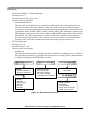
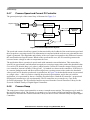
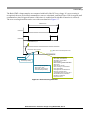
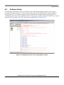
The main software flow chart incorporates the main routine (background loop) entered from reset, and the
interrupt events. The main routine includes the initialization of the microcontroller and the main loop.
After initialization, the main routine enters an endless loop, which executes the application state machine
consisting of init, stop, alignment, startup, run, and error states. The transition between the states depends
on the state of the START/ STOP switch and the drive status. The main software flow chart is given
in Figure 5-1. Apart from the background loop, the software incorporates the following three interrupts:
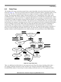
• Dual Timer Channel 0 Compare Interrupt
Interrupt Level: 2
Execution Period: 6 μs
Functions called by interrupt:
— IsrAdcStartRead
Fast interrupt routine, which performs a start conversion and reads the results of ADC. Physical
quantities that are measured: three Back-EMF voltages with a two-sample averaging process,
DC-bus voltage and DC-bus current. The next task of this function is the switching between
ADC channels, first and last sample recognition, zero-crossing detection, and zero-crossing to
commutation time calculation. When a zero crossing is detected, the actual value of iDcb is
added to iDcbSum, zcToCmt time is added to periodSum, and the zero-crossing counter zcCnt
is incremented for the next averaging process.
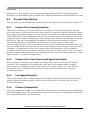
— IsrAdcBlock
Fast interrupt routine, which is launched after a commutation and performs the testing of the
selected Back-EMF for 20-80 % of DC-bus voltage.
BLDC Sensorless Reference Design Using MC56F8006, Rev. 0
Freescale Semiconductor
5-1