1
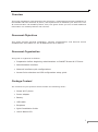
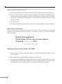
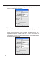
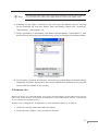
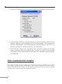
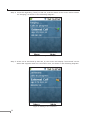
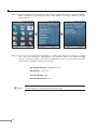
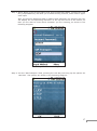
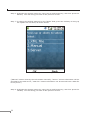
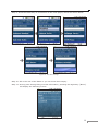
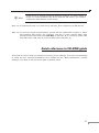
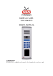
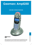
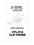
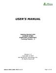
Table of Contents PREPARATION BEFORE BEGINNING ADMINISTRATION ON THE WI-FI PHONE ADMINISTRATION INTERFACE 2 6 Inserting the Battery 6 Charging the Battery 7 Powering Up the Phone for the 1ST TIME 8 Access Point Selection IP Address Info 9 11 VOICE COMMUNICATION SAMPLES 12 Peer To Peer (P2P) mode 13 SIP Proxy mode 15 QUICK REFERENCE IN CD-ROM GUIDE 21 This page is intentionally left blank Overview This quick installation guide describes the objectives; organization and basic installation of the PLANET VIP-191 smart Wi-Fi phone, and explains how to establish your first voice over IP communication via PLANET product. Also, this guide shows you how to find additional information on related products and services. Document Objectives This guide provides physical installation, network configurations, and Internet access establishment information for the PLANET Smart Wi-Fi Phones. Document Organization This guide is organized as follows: • Preparation before beginning administration on PLANET Smart Wi-Fi Phone • Administration interface • Network interface quick configurations • Access Point selection and SIP configuration setup guide Package Content The contents of your product should contain the following items: • Smart Wi-Fi phone • Power adapter • Battery • USB cable • Earphone • Quick Installation Guide • User’s Manual CD 1 Preparation before beginning administration on the Wi-Fi Phone Front view and keypad function: Figure 1. Front view of VIP-191 2 Keypad Description The LED denotes different conditions to show the following status: Green: This indicates the battery is being re-charged, and the phone is connected to an Access Point. 1 LED Red: This indicates the battery is being re-charged, and the phone is not connected to an Access Point. Flashing green: This indicates the phone is connected to an Access Point. Flashing red: This indicates the phone is not connected to an Access Point. 2 Receiver 3 Camera 4 Up Key It can hear the sounds from here. You can take a self-portrait by having the camera facing yourself, or you can take a picture of others by rotating the camera to face outward. 5 This key allows the user to navigate in an upward direction. Backward This key allows the user to navigate in a backward or left Key direction. Left / Tab This key allows the user to select and choose the “soft key” Key presented at the bottom left of the screen. 7 Down Key This key allows the user to navigate in a downward direction. 8 Call Key 6 This key allows the user to make an outgoing call, and accept an incoming call. These keys are used to compose phone numbers, or create any text input for applications. Pressing the digit keys will generate characters in a round robin fashion, as shown in the following table: 9 Digit Keys Key Output Key Output 1 1 @ : / \ _ - ? ! , . ; “ ‘ () 7 pqrs7 2 abc2 8 tuv8 3 def3 9 wxyz9 4 ghi4 0 0 space + & $ % ^ <> = 5 jkl5 * * 6 mno6 # # Note: Pressing the # Key will toggle between lower and upper case. 3 This key corresponds to the Enter Key of a standard keyboard. 10 OK Key It enables the user to select and confirm different menu selections or data input. 11 12 Forward This key allows the user to navigate in a forward or right Key direction. Right Key End / 13 Power Key This key allows the user to select and choose the “soft key” presented at the bottom right of the screen. This key serves as a power on/off switch for the phone, when it is pressed for several seconds. Just pressing on this button once will allow the user to hang up or refuse a phone call, or close the current window. Pressing this key will allow the user to navigate to the previous 14 Back Key page during Internet browsing or menu selection. This key also serves as a backspace to correct any type mistakes. Pressing this key will return to: 15 Home Key i) The default home page while browsing the Internet. ii) The Main screen while not using the Internet Explorer. Table 1. Front view description of VIP-191 Rear view and keypad function: Figure 2. Rear Panel of VIP-191 4 Keypad Description 1 Loudspeaker The sounds will sent out from here. 2 Battery Cover It can remove the battery cover to install/ un-install battery. 3 USB It can connect the USB adapter charge to charge, or connect USB cable to carry out synchronization with PC. Table 2. Rear view description of VIP-191 Side view and keypad function: Figure 3. Side Panel of VIP-191 5 Keypad Description 1 Infrared It can deliver and receive the data by 2 Earpiece Cap Removing this cap and it can plug the extend 3 Soft Reset Button infrared device. earpiece device. Pressing the reset button to reboot the phone. 4 Mini SD Cap Removing this cap and it can install/ un-install the SD card. 5 Select Link / Volume Button Pressing this key will allow the user to set the focus on the links on a web page. Pressing the OK Key while the focus is on a link is equivalent to clicking on a link in Windows. This key also allows user to adjust the volume during video conferencing. 6 Image Capture Button Pressing this key will allow the user to capture the image in front while the camera application is running. Table 3. Side view description of VIP-191 Administration Interface The Wi-Fi phone only provides keypad for machine management and administration. Inserting the Battery Before you can use the Wi-Fi phone, you have to insert the battery into the phone. Note that if you are using the phone for the first time, the battery needs to be fully charged. To insert the battery, carry out the following steps: 1. To open the phone, slide the phone cover towards the bottom of the phone. 2. Align the golden contacts of the battery with the corresponding connectors on the phone, and push the opposite end of the battery until it snaps into place. 3. Close the phone cover by sliding it towards the top of the phone. 4. Press the red Power Key to turn on the phone. 6 Charging the Battery On First Use 1. Insert the battery, press the red Power Key and turn on the phone. 2. Connect the power cord to the USB slot located at the base of the phone. 3. Connect the charger to an AC wall outlet. 4. The battery can be fully charged within 3~4 hours. Then disconnect the charger first from the phone and the AC outlet Hint If you are using the phone for the first time, the battery needs to be fully charged before use. On Subsequent Use On subsequent use, if the power level of the battery is low, the following orange text may be displayed at boot up: Low Battery…. Please insert charger! Figure 4. Low battery prompt If you then insert the power adapter charging cable to the phone, the following orange text will be displayed: Charging……….. Figure 5. Battery charging prompt After a period of 60-80 minutes, the battery should be fully charged. 7 In the event that the battery is totally drained out, the following recovery procedure will start the battery charging function: 1. Remove the battery. Re-insert the battery and charging cable into the phone. 2. Wait for a short while, and the orange characters will show up indicating that the phone is being recharged. (Those orange letters will take a while to show up, though the phone starts being re-charged the moment you plug in the charging cable.) 3. OS will boot up. 4. Save the cable inserted and the phone turned on until the battery is fully re-charged. When Phone is Turned Off You can charge the phone when it is switched off. (Please refer to the section “Turning Off The Phone” on how to switch off the phone.) The following orange text will be displayed during charging: Battery Charging Mode Press Power On key once to start system. Charging ………………. 60% Figure 6. Battery charging status Powering Up the Phone for the 1ST TIME 1. To power up the phone, insert the battery, and press the red Power Key to turn on the phone. 2. When the phone is booted up, it will give a ring sound. 3. The phone will display the screen of the Normal mode. (Please refer to this as the Main Screen from User’s Manual for more understandings.) At this point, all initialization is complete, and you can start to operate the phone. 8 Access Point Selection To connect to the Wi-Fi network, the phone has to connect to an Access Point (AP). To do so, carry out the following steps: 1. From the Main Screen, press the Left Button (“Menu”) and select “1. AP Connection”, the following screen should appear: Figure 7. Main screen of VIP-191 2. Press the OK button (or the Left Key), and a screen showing the available APs and their corresponding signal strength will appear. (The precise definition of the number that corresponds to the signal level is called Signal To Noise Ratio, which indicates the noise level of an AP. The higher the number, the less noise the AP has.) Also, if there is a icon in front of the signal bar, it indicates that the AP requires a network key. Figure 8. Wireless information 9 3. Press the Down Key to highlight the desired Access Point to be connected. 4. Once an AP is highlighted, press the Right (“Select”) key and the following screen of the AP settings will appear: Figure 9. AP setting 5. If the AP requires no encryption or authentication, you can just press the OK button. However, if encryption or authentication is required, you can press on the Down Key to move to the Authentication field, and use the Forward and Backward Keys to select the authentication setting. Repeat the same procedure for the Encryption field. If the network key is automatically provided, press the Down Key to move to the checkbox that says “The key is provided automatically” and press on the OK Key to check the checkbox; otherwise, you have to manually enter the key at the Network Key text box, as shown below: 10 Figure 10. AP setting - Encryption Hint If both lower and upper case letters are needed in entering the network key, pressing the # Key will toggle between lower and upper case. 6. Pressing on the Right (“Connect”) key will have the phone tried to connect to the selected AP, and the Status field will display status like “scanning”, “associating”, “associated”, etc. 7. If the connection is successful, the status should display “Connected to”, and there will be a blue ring on the antenna icon of the connected AP, as shown below: Figure 11. AP connection status 8. At this point, pressing the OK Key will bring the phone back to Normal Mode, displaying the Main Screen with the newly obtained IP address on the top left corner and the middle of the screen. IP Address Info When the phone is in Normal Mode, the screen should display the IP address on the top left corner of the screen. (It will also be displayed in the middle of the screen, if the phone is not connected to a SIP server). Another way to display the IP address in a more detailed fashion is as follows: 1. Click the Left Key and select AP Connection. 2. Press the Left (“Menu”) Key and select “IP Info”. 11 3. A screen with more detailed IP information will then be displayed, as shown below: Figure 12. IP information 4. Press the Right (“Renew”) Key will attempt to refresh the screen with a new IP address, (though a new IP address may not be guaranteed.) The settings of IP Address, Subnet Mask, and Default Gateway will temporarily be set to 0.0.0.0 and they will then be refreshed with the new information. 5. Press the Left (“Menu”) Key and select “Exit” will take you back to the Main screen; whereas selecting “Wireless Info” will take you back to the Wireless Information screen where different APs with their respective signal strengths are displayed. Voice communication samples The chapter shows you the concept and command to help you configure your smart Wi-Fi phone through sample configuration. And provide instruction to make calls to desired destination in Wi-Fi phone. In this section, we’ll lead you step by step to establish your first voice communication via keypad operations. 12 Peer To Peer (P2P) mode Figure 13. Topology of instruction example - P2P mode Step 1: Assuming there are two VIP-191 in the network the IP address are 172.0.0.11 and 172.0.0.12 Step 2: Press the Dial Key of VIP-191_A. Step 3: Enter the IP address of VIP-191_B (as shown below). Enter the ‘.’ in the IP address, press the ‘*’ Key twice. Figure 14. Making a call - Entry the IP address 13 Step 4: Press the Right Key (“Dial”) to dial out, and the status of the screen will be shown as “Ringing”, as shown in the following diagram: Figure 15. Making a call - Ringing Step 5: If the call is answered by VIP-191_B, the screen will display “Connected” on the status bar together with the connection time, as shown in the following diagram: Figure 16. Making a call - Connected 14 Step 6: At any time, the user can press the red End Key to hang up the call, and the phone will return to the Main screen. The VIP-191_B can reversely make calls to the VIP-191_A. SIP Proxy mode Figure 17. Topology of instruction example - Proxy mode To connect to a SIP server, you can carry out the following steps: Step 1: Make sure the VIP-191_A is connected to an AP. 15 Step 2: From the Main Screen, press the Left (“Menu”) Key and select “3. Profile Setting”. Select “Standard”, press OK and select “Edit Profile” from the submenu, just as shown below: Figure 18. Profile setting of VIP-191 Step 3: Fill in the corresponding information. Usually the fields that need to be filled are: “My Phone Number”, “SIP Server” (i.e. domain name or IP address of SIP server), “Account Name”, and “Account Password”, and you can leave the other fields with the default values. An example: My Phone Number: [email protected] SIP Server: 172.0.0.1 Account Name: 882 Account Password: 123 Hint 16 The SIP standard requires you to include the “@” sign and the SIP server domain in the My Phone Number field. Step 4: When filling in the Account Name and Account Password fields, pressing the Left Key (“Input Method”) will allow you to switch among numeric, lower case or upper case input. Also, the Account Password field is masked with asterisks, but pressing any key will display the corresponding character on the top left corner of the screen, so that you are able to know which character you are entering, as shown in the following diagram: Figure 19. SIP account setting Step 5: For the “SIP Transport” field, pressing the Left Key will bring up the options for this field. The options are shown in the following diagram: Figure 20. SIP transport setting 17 Step 6: Highlight the desired option by using the Up and Down Key, and then press the OK Key. This will bring you back to the previous screen. Step 7: To change the default settings for the “Mode” field, press the Left Key to bring up the options for this field, as shown below: Figure 21. Mode setting (“Manual” means entering the information manually; “Server” means information will be provided by the SIP server; “XML File” means information can be derived from a XML file in the phone.) Step 8: Highlight the desired option by using the Up and Down Key, and then press the OK Key. This will bring you back to the previous screen. 18 Step 9: Press the Down Key to scroll down to the next pages, which are shown below: Figure 22. The other settings Step 10: Fill in the rest of the fields or you can leave them empty. Step 11: At any point during filling out this information, pressing the Right Key (“Next”) will display the following screen: Figure 23. Confirm prompt 19 Step 12: Press the Left (“OK”) key to save the information. Then press the Right (“Back”) Key to go back up one level. Selecting “Activate” and pressing the Left Key will attempt to connect to the specified SIP server, as shown below: Figure 24. Activate profile prompt Step 13: If connection is successful, the number returned from the SIP server will be displayed on the Main Screen (replacing the words “Windows CE”), just as shown below: Figure 25. Main screen - with account number 20 Hint A SIP server is usually located at another network. In other words, if there is a router between the phone and the SIP server, you need to enable the uPnP feature in the router. Step 14: To repeat the step 1~13 and set up VIP-191_B for registering to SIP Server. Step 15: To verify the VoIP communication, please dial the destination number to make call between SIP clients. For example, VIP-191_A (with number 882) with keypad number 883 and press Call Key to VIP-191_B; or reversely make calls from SIP client (VIP-191_B) to the number 882 (VIP-191_A). Quick reference in CD-ROM guide This guide is used to help you startup your Wi-Fi phone settings. It is also recommended to check the user manual CD-ROM for more details like the “Basic Operations”, “Profile Settings”, and how to set the device back to default value. 21 This page is intentionally left blank