1
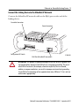
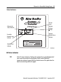
Installation Instructions
Ethernet-to-DeviceNet Linking Device
Catalog Number 1788-EN2DN
This publication tells you how to install the 1788-EN2DN
Ethernet-to-DeviceNet linking device and use RSNetWorx™ for DeviceNet
software to configure it.
Topic
Page
Important User Information
2
About the Linking Device
6
System Requirements
7
Installing and Configuring the Linking Device
8
Using Diagnostic Web Pages
44
Dimensions
49
DeviceNet Connector Pinouts
50
EtherNet/IP RJ45 Connector Pinouts
50
Specifications
51
Additional Resources
55
2 Ethernet-to-DeviceNet Linking Device
Important User Information
Solid-state equipment has operational characteristics differing from those of electromechanical equipment. Safety Guidelines
for the Application, Installation and Maintenance of Solid State Controls (publication SGI-1.1 available from your local
Rockwell Automation™ sales office or online at http://www.rockwellautomation.com/literature/) describes some important
differences between solid-state equipment and hard-wired electromechanical devices. Because of this difference, and also
because of the wide variety of uses for solid-state equipment, all persons responsible for applying this equipment must satisfy
themselves that each intended application of this equipment is acceptable.
In no event will Rockwell Automation, Inc. be responsible or liable for indirect or consequential damages resulting from the
use or application of this equipment.
The examples and diagrams in this manual are included solely for illustrative purposes. Because of the many variables and
requirements associated with any particular installation, Rockwell Automation, Inc. cannot assume responsibility or liability
for actual use based on the examples and diagrams.
No patent liability is assumed by Rockwell Automation, Inc. with respect to use of information, circuits, equipment, or
software described in this manual.
Reproduction of the contents of this manual, in whole or in part, without written permission of Rockwell Automation, Inc., is
prohibited.
Throughout this manual, when necessary, we use notes to make you aware of safety considerations.
WARNING: Identifies information about practices or circumstances that can cause an explosion in a
hazardous environment, which may lead to personal injury or death, property damage, or economic loss.
ATTENTION: Identifies information about practices or circumstances that can lead to personal injury or
death, property damage, or economic loss. Attentions help you identify a hazard, avoid a hazard and
recognize the consequences.
SHOCK HAZARD: Labels may be on or inside the equipment, for example, drive or motor, to alert people
that dangerous voltage may be present.
BURN HAZARD: Labels may be on or inside the equipment, for example, drive or motor, to alert people
that surfaces may reach dangerous temperatures.
IMPORTANT
Identifies information that is critical for successful application and understanding of the product.
Rockwell Automation Publication 1788-IN055C-EN-P - September 2011
Ethernet-to-DeviceNet Linking Device 3
North American Hazardous Location Approval
The following information applies when
operating this equipment in hazardous
locations.
Informations sur l’utilisation de cet équipement
en environnements dangereux.
Products marked “CL I, DIV 2, GP A, B, C, D” are
suitable for use in Class I Division 2 Groups A, B, C, D,
Hazardous Locations and nonhazardous locations
only. Each product is supplied with markings on the
rating nameplate indicating the hazardous location
temperature code. When combining products within
a system, the most adverse temperature code
(lowest “T” number) may be used to help determine
the overall temperature code of the system.
Combinations of equipment in your system are
subject to investigation by the local Authority
Having Jurisdiction at the time of installation.
Les produits marqués "CL I, DIV 2, GP A, B, C, D" ne
conviennent qu'à une utilisation en environnements de
Classe I Division 2 Groupes A, B, C, D dangereux et non
dangereux. Chaque produit est livré avec des marquages
sur sa plaque d'identification qui indiquent le code de
température pour les environnements dangereux.
Lorsque plusieurs produits sont combinés dans un
système, le code de température le plus défavorable
(code de température le plus faible) peut être utilisé
pour déterminer le code de température global du
système. Les combinaisons d'équipements dans le
système sont sujettes à inspection par les autorités
locales qualifiées au moment de l'installation.
WARNING:
Explosion Hazard • Do not disconnect equipment
unless power has been removed or
the area is known to be
nonhazardous.
• Do not disconnect connections to
this equipment unless power has
been removed or the area is known
to be nonhazardous. Secure any
external connections that mate to
this equipment by using screws,
sliding latches, threaded
connectors, or other means
provided with this product.
• Substitution of components may
impair suitability for Class I,
Division 2.
• If this product contains batteries,
they must only be changed in an
area known to be nonhazardous.
AVERTISSEMENT:
Risque d’Explosion –
• Couper le courant ou s'assurer que
l'environnement est classé non
dangereux avant de débrancher
l'équipement.
• Couper le courant ou s'assurer que
l'environnement est classé non
dangereux avant de débrancher les
connecteurs. Fixer tous les
connecteurs externes reliés à cet
équipement à l'aide de vis, loquets
coulissants, connecteurs filetés ou
autres moyens fournis avec ce produit.
• La substitution de composants peut
rendre cet équipement inadapté à une
utilisation en environnement de
Classe I, Division 2.
• S'assurer que l'environnement est
classé non dangereux avant de
changer les piles.
Rockwell Automation Publication 1788-IN055C-EN-P - September 2011
4 Ethernet-to-DeviceNet Linking Device
European Hazardous Location Approval
The following applies when the product bears the Ex Marking.
This equipment is intended for use in potentially explosive atmospheres as
defined by European Union Directive 94/9/EC and has been found to comply
with the Essential Health and Safety Requirements relating to the design and
construction of Category 3 equipment intended for use in Zone 2 potentially
explosive atmospheres, given in Annex II to this Directive.
Compliance with the Essential Health and Safety Requirements has been
assured by compliance with EN 60079-15 and EN 60079-0.
WARNING: This equipment must be installed in an enclosure providing at least
IP54 protection when applied in Zone 2 environments.
This equipment shall be used within its specified ratings defined by Rockwell
Automation.
Provision shall be made to prevent the rated voltage from being exceeded by
transient disturbances of more than 40% when applied in Zone 2 environments.
Secure any external connections that mate to this equipment by using screws,
sliding latches, threaded connectors, or other means provided with this product.
Do not disconnect equipment unless power has been removed or the area is known
to be nonhazardous.
ATTENTION: This equipment is not resistant to sunlight or other sources of UV
radiation.
Rockwell Automation Publication 1788-IN055C-EN-P - September 2011
Ethernet-to-DeviceNet Linking Device 5
Environment and Enclosure
ATTENTION: This equipment is intended for use in a Pollution Degree 2 industrial
environment, in overvoltage Category II applications (as defined in IEC 60664-1), at
altitudes up to 2000 m (6562 ft) without derating.
This equipment is considered Group 1, Class A industrial equipment according to
IEC/CISPR 11. Without appropriate precautions, there may be difficulties with
electromagnetic compatibility in residential and other environments due to
conducted and radiated disturbances.
This equipment is supplied as open-type equipment. It must be mounted within an
enclosure that is suitably designed for those specific environmental conditions that
will be present and appropriately designed to prevent personal injury resulting
from accessibility to live parts. The enclosure must have suitable flame-retardant
properties to prevent or minimize the spread of flame, complying with a flame
spread rating of 5VA, V2, V1, V0 (or equivalent) if non-metallic. The interior of the
enclosure must be accessible only by the use of a tool. Subsequent sections of this
publication may contain additional information regarding specific enclosure type
ratings that are required to comply with certain product safety certifications.
In addition to this publication, see the following:
• Industrial Automation Wiring and Grounding Guidelines, publication
1770-4.1, for additional installation requirements
• NEMA Standard 250 and IEC 60529, as applicable, for explanations of the
degrees of protection provided by enclosures
ATTENTION: Prevent Electrostatic Discharge
This equipment is sensitive to electrostatic discharge, which can cause internal
damage and affect normal operation. Follow these guidelines when you handle
this equipment:
•
•
•
•
•
•
Touch a grounded object to discharge potential static.
Wear an approved grounding wriststrap.
Do not touch connectors or pins on component boards.
Do not touch circuit components inside the equipment.
Use a static-safe workstation, if available.
Store the equipment in appropriate static-safe packaging when not in use.
Rockwell Automation Publication 1788-IN055C-EN-P - September 2011
6 Ethernet-to-DeviceNet Linking Device
About the Linking Device
The 1788-EN2DN Ethernet-to-DeviceNet linking device lets you seamlessly
connect your information- or control-level networks with your device-level
network.
The linking device provides full DeviceNet master functionality, so you can
connect up to 63 DeviceNet slave devices to an Ethernet TCP/IP interface that
supports the EtherNet/IP network and an HTTP web server. As examples, you
could use the linking device:
• as a gateway to connect information- or control-level networks to
device-level networks for programming, configuration, control, or data
collection.
• as a router/bridge to connect the EtherNet/IP network to the
DeviceNet network.
The linking device provides centralized data storage, or I/O tables, for data
shared between the DeviceNet and EtherNet/IP networks. Data is placed into
the I/O tables by one network interface, allowing the data to be read through the
other network interface.
The linking device appears as a single device on either network by using standard
protocol mechanisms. No special, or extended, protocol features are required for
the devices on either network to read or write the data flowing through the I/O
tables; all cross-network activity is transparent to the devices on either network.
All connections, whether power or fieldbus, to the linking device are made on
one end of the module. Phoenix connectors are provided for power and
DeviceNet connections. A RJ45 style connector is provided for EtherNet/IP
connection.
The linking device can be mounted to a DIN rail.
Rockwell Automation Publication 1788-IN055C-EN-P - September 2011
Ethernet-to-DeviceNet Linking Device 7
System Requirements
The following hardware and software components are required to use the
linking device.
Required Hardware
• 1788-EN2DN linking device
• DeviceNet cabling, power, and devices forming a DeviceNet network
• Ethernet cabling and power
• Computer with access to the Ethernet network
• Computer running DeviceNet configuration software
The DeviceNet slave devices with which the linking device
communicates are specified using a DeviceNet Configuration Software
tool such as RSNetWorx for DeviceNet software.
• 24V DC power to the linking device
DeviceNet power may be used; however, using DeviceNet power
bypasses the DeviceNet network isolation.
Required Software
• DeviceNet configuration software, such as RSNetWorx for DeviceNet
software, version 4.01 or later, to configure DeviceNet devices and the
linking device’s DeviceNet functionality
• RSLinx® software, version 2.31 or later
• DHCP server 2.3.2 or later, which ships with RSLinx software version
2.42 and later. If you are using an earlier version of RSLinx software, you
will need to download the standalone server from
http://www.rockwellautomation.com/support
Rockwell Automation Publication 1788-IN055C-EN-P - September 2011
8 Ethernet-to-DeviceNet Linking Device
Optional Software
RSLogix™ 5000 software, version 13 or later.
Installing and Configuring the Linking Device
WARNING: If you connect or disconnect the communication cable with power
applied to this module or any device on the network, an electrical arc can occur. This
could cause an explosion in hazardous location installations.
If you connect or disconnect wiring while the field-side power is on, an electrical arc
can occur. This could cause an explosion in hazardous location installations. Be sure
that power is removed or the area is nonhazardous before proceeding.
When you change switch settings while field-side power is on, an electrical arc can
occur. This could cause an explosion in hazardous location installations.
Be sure that power is removed or the area is nonhazardous before proceeding.
Follow these steps to install the linking device (described in the sections that
follow).
Rockwell Automation Publication 1788-IN055C-EN-P - September 2011
Ethernet-to-DeviceNet Linking Device 9
Connect the Linking Device to the EtherNet/IP Network
Connect the EtherNet/IP network cable to the RJ45 port on the end of the
linking device.
DeviceNet Connection
Power Connection
Configuration DIP Switch
RJ45 Port (EtherNet/IP Connection)
31480-M
ATTENTION: This product is grounded through the DIN rail to chassis ground. Use
zinc plated yellow-chromate steel DIN rail to assure proper grounding. The use of
other DIN rail materials (for example, aluminum or plastic) that can corrode,
oxidize, or are poor conductors, can result in improper or intermittent grounding.
Secure DIN rail to mounting surface approximately every 200 mm (7.8 in.) and use
end-anchors appropriately.
Rockwell Automation Publication 1788-IN055C-EN-P - September 2011
10 Ethernet-to-DeviceNet Linking Device
Connect the Linking Device to the DeviceNet Network
ATTENTION:
Do not wire more than 2 conductors on any single terminal.
To comply with the CE Low Voltage Directive (LVD), this equipment must be
powered from a source compliant with Safety Extra Low Voltage (SELV) or
Protected Extra Low Voltage (PELV).
To comply with UL restrictions, this equipment must be powered from a source
compliant with Class 2 or Limited Voltage/Current.
1. Make sure a computer running RSNetWorx for DeviceNet software is
connected to the EtherNet/IP network.
2. With power to the linking device off, connect the DeviceNet network
cable to the DeviceNet connector on the linking device.
The female terminal block connector is provided with the linking
device.
(Red) Net Power 24V DC
(White) CAN High +
CAN Shield
(Blue) CAN Low
(Black) Net Power 24V DC Common
31442-M
3. Connect the power cable to the linking device.
The female terminal block connector is provided with the linking
device.
Rockwell Automation Publication 1788-IN055C-EN-P - September 2011
Ethernet-to-DeviceNet Linking Device 11
..
24V DC common
24V DC +
TIP
Two 120 ohm termination resistors (supplied with the linking device) may be
required for proper network termination at each end of the trunk line. See the
DeviceNet Specification (available from the Open DeviceNet Vendors
Association at http://www.odva.org) for specific rules on DeviceNet
connections and termination.
4. Apply power to the linking device and DeviceNet network.
IMPORTANT
The linking device defaults to Autobaud. This means that the linking device
automatically finds the network communication rate at when power is
applied. You must specify a master device, such as a DeviceNet Bridge Module
(catalog number 1756-DNB) so that the linking device can pick up the correct
communication rate. If you do not have another device installed, you must
use RSNetWorx for DeviceNet software to set the communication rate, as
described in Set the DeviceNet MAC ID and Communication Rate on page 21.
Do not attempt to commission the linking device on a network configured at
a different communication rate.
Rockwell Automation Publication 1788-IN055C-EN-P - September 2011
12 Ethernet-to-DeviceNet Linking Device
Configure the Linking Device IP Address
Several methods may be used to set the IP Address. These methods include the
following:
• IP address configuration DIP switch
• DHCP protocol
• Web page
• RSLogix 5000 software, version 13 or later), and 1788-EN2DN Linking
Device, revision 2.x or later
Setting the IP Address with the Configuration DIP Switch
A configuration DIP switch on the end of the linking device lets you set the IP
address. If the configuration DIP switch is set to 1 (in the up position, as shown
in the following figure), when power is applied to the switch, the value of the
switch creates the IP address of 192.168.1.1.
The numbers that appear above the switches on the DIP switch do not
correspond to bit locations in the address value. The numbers on the switch
are opposite the address value bit locations; for example, bit 0 is set by
switch 8.
IMPORTANT
IP Address Configuration DIP Switch
7
8
2
6
3
5
4
4
5
3
6
2
7
1
ON
8
1 ON
31421-M
Rockwell Automation Publication 1788-IN055C-EN-P - September 2011
Ethernet-to-DeviceNet Linking Device 13
The switch represents the binary value of the last byte in the 4-byte IP address. In
this case it is n. If n = 0, the linking device obtains its IP address from the
software configuration (DHCP or web page).
IP address
192.168.1.n
Subnet mask
255.255.255.0
Gateway address
0.0.0.0 (No gateway set)
Setting the IP Address By Using DHCP/BootP
TIP
The use of DHCP is the default configuration for the linking device as shipped.
The IP address configuration DIP switch ships with n =0.
When DHCP/BootP is enabled and a DHCP or BootP server is found, the
IP address, Subnet mask, and Gateway address are automatically configured
by the DHCP server, as shown in the following figure.
Automatic Configuration
Follow these steps to change the IP address, Subnet mask, and Gateway address
from this dialog box.
Rockwell Automation Publication 1788-IN055C-EN-P - September 2011
14 Ethernet-to-DeviceNet Linking Device
1. Click New.
You see the Properties dialog box.
2. On the Properties dialog box, enter the appropriate values into the
following fields.
• Ethernet address (MAC ID) [from the linking device product ID
label]
• IP address
• Subnet Mask
• Gateway (IP address)
3. Click OK.
Rockwell Automation Publication 1788-IN055C-EN-P - September 2011
Ethernet-to-DeviceNet Linking Device 15
The following figure shows a flowchart describing how the IP configuration is
determined when the linking device is powered up.
Start
Valid
Configuration
in Flash Memory?
No
Yes
DIP Switch = 0
Yes
No
Request config
from DHCP/
BOOTP Server.
Timeout 30 secs
Use received
configuration
Yes
Yes
DHCP
Config
Received?
DHCP
Enabled?
IP = 192 168.1.n
Sub = 255.255.255.0
No Gateway
No
No
Valid
Configuration
File?
Yes
Use Valid (stored)
IP address
No
Remain offline
Stop
TIP
31445-M
You can enable these values using the linking device’s IP Configuration web
page. Refer to Setting the IP Address Using By Using the Web Page on
page 16.
Rockwell Automation Publication 1788-IN055C-EN-P - September 2011
16 Ethernet-to-DeviceNet Linking Device
Setting the IP Address Using By Using the Web Page
The EtherNet/IP address can also be configured using the IP Configuration web
page on the linking device, as shown in the following figure.
The IP address can be set with the web page only if the linking device already has
a valid IP address. Typically, you can do this by using the DIP switch to force the
linking device to use a temporary IP address after you cycle power. Follow these
steps to configure the IP address with the web page.
IMPORTANT
Because the DIP switch setting overrides other IP address configurations, be
sure to set the DIP switch to the 0 position before continuing.
1. Browse to the linking device by entering the temporary IP address in
your web browser’s address bar and click Enter.
2. In the left pane, click IP Configuration.
You see the Enter Network Password dialog box.
3. In the Username field, enter Administrator.
Rockwell Automation Publication 1788-IN055C-EN-P - September 2011
Ethernet-to-DeviceNet Linking Device 17
4. Leave the password field blank.
5. Click OK.
You see the IP Configuration dialog box.
Rockwell Automation Publication 1788-IN055C-EN-P - September 2011
18 Ethernet-to-DeviceNet Linking Device
6. Enter the following values into the IP Configuration dialog box.
In this field
Enter
IP Address
Any valid value. See your system administrator for a
valid IP address.
Subnet Mask
Gateway IP Address
Any valid value.
DHCP enabled
7. Click Submit Values.
8. Follow the on-dialog box prompts.
9. Click the Reset Module button to reset the linking device.
Register the Driver in RSLinx Software
1. In RSLinx software, choose Communications>Configure Driver.
2. In the Configure Drivers menu, choose Ethernet Devices from the
Available Driver Types pull-down menu.
3. Click Add New.
4. In the Add New RSLinx Drivers pop-up menu, click OK.
5. In the Configure Driver window that appears, enter the IP address of the
linking device.
6. Click Close.
7. Click OK.
Rockwell Automation Publication 1788-IN055C-EN-P - September 2011
Ethernet-to-DeviceNet Linking Device 19
(Optional) Register the EDS file in RSNetWorx Software
RSNetWorx for DeviceNet software requires an electronic data sheet (EDS) to
recognize a device and its capabilities. If you do not already have a registered
EDS file for the device, you can download an EDS file from
http://www.rockwellautomation.com/support/downloads.html.
IMPORTANT
If RSLinx or RSNetWorx for DeviceNet software cannot find the EDS file for the
linking device, the linking device’s icon may be labeled an unrecognizable
device in the software.
1. In RSNetWorx for DeviceNet software, choose Tools>EDS Wizard.
2. Click Next.
3. Select Register an EDS File and click Next.
4. Select Register a Single File and enter or browse to the location of the
EDS file for the linking device.
5. Click Next or Finish for the remaining option dialog boxes.
Use RSNetWorx for DeviceNet Software to Locate the Module on the Network
1. In RSNetWorx for DeviceNet software, choose Network>Online.
2. In the left pane, click the RSLinx Ethernet driver you added previously.
Refer to Use RSNetWorx for DeviceNet Software to Locate the Module
on the Network on page 19.
3. In the left pane, click the + next to the 1788-EN2DN linking device
icon.
Rockwell Automation Publication 1788-IN055C-EN-P - September 2011
20 Ethernet-to-DeviceNet Linking Device
4. In the left pane, click DeviceNet, DeviceNet.
5. When asked to upload from the network, click OK to perform a single
pass browse.
Rockwell Automation Publication 1788-IN055C-EN-P - September 2011
Ethernet-to-DeviceNet Linking Device 21
Set the DeviceNet MAC ID and Communication Rate
1. In RSNetWorx for DeviceNet software, choose Tools>Node
Commissioning.
You see the Node Commissioning dialog box.
2. On the Node Commissioning dialog box, click Browse.
You see the Device Selection dialog box.
Rockwell Automation Publication 1788-IN055C-EN-P - September 2011
22 Ethernet-to-DeviceNet Linking Device
3. In the left pane, click the + next to the RSLinx driver for the
1788-EN2DN linking device.
4. In the left pane of the dialog box, click the + next to the IP address for
the 1788-EN2DN linking device.
5. In the left pane, click the + next to the DeviceNet network.
You see the 1788-EN2DN linking device in the left pane.
6. Click on the 1788-EN2DN linking device in the left pane.
It appears in the right pane.
7. Click OK.
8. If a warning text box asking you if you wish to continue appears, click
Yes.
Rockwell Automation Publication 1788-IN055C-EN-P - September 2011
Ethernet-to-DeviceNet Linking Device 23
9. Enter the desired MAC address or data rate, then click Apply.
10. Click Close.
IMPORTANT
The linking device will automatically reset if a new MAC ID is entered. If only
the communication rate is changed you must cycle power to the linking
device before the new communication rate will take effect.
When the MAC ID is changed, the linking device’s I/O configuration is cleared.
11. Restart RSNetworx for DeviceNet software and go online.
TIP
If you are using the linking device as a network gateway, you may need to
restart RSNetWorx for DeviceNet software before continuing.
Rockwell Automation Publication 1788-IN055C-EN-P - September 2011
24 Ethernet-to-DeviceNet Linking Device
(Optional) Disable Autobaud
If you do not want the linking device to automatically determine the network
communication rate, disable Autobaud. By default, the linking device has
Autobaud enabled.
1. In RSNetWorx for DeviceNet software, highlight the linking device by
clicking on its icon.
2. From the pull-down menu, choose Device>Class Instance Editor.
3. If a warning text box appears, click Yes.
You see the Class Instance Editor dialog box.
4. From the pull-down menu, choose Description>Set Single Attribute.
Rockwell Automation Publication 1788-IN055C-EN-P - September 2011
Ethernet-to-DeviceNet Linking Device 25
In this field
Select
Object Address
Class
Instance
Attribute
3
1
64h
Data Sent to Device
00 to enable Autobaud
01 to disable Autobaud
Transmit Data Size
Byte
IMPORTANT
Make sure the Values in Decimal checkbox is not checked.
5. Click Execute.
Rockwell Automation Publication 1788-IN055C-EN-P - September 2011
26 Ethernet-to-DeviceNet Linking Device
You should see a message in the Data received from device field
indicating that the execution was completed.
IMPORTANT
Changes to the autobaud option configuration do not take effect until you
cycle power to the linking device. You may also have to cycle power to the
slave devices.
If the linking device is the only master on the DeviceNet network, do not
enable autobaud. Automatic communication detection requires traffic on the
network. There is typically no traffic until the master establishes connections.
6. Click Close.
Rockwell Automation Publication 1788-IN055C-EN-P - September 2011
Ethernet-to-DeviceNet Linking Device 27
(Optional) Configure DeviceNet I/O
IMPORTANT
Steps 8 and 9 are required only if the linking device is used as an I/O scanner.
The linking device can function as a gateway/bridge, even if no I/O is
configured.
I/O Mapping
The DeviceNet I/O configuration defines the format of the Input and Output
tables, or the mapping of DeviceNet slaves’ I/O data to the I/O tables. As slaves
are added to the linking device’s DeviceNet scanner configuration, the location
in the I/O tables of each part of the slave’s I/O data is determined and stored.
IMPORTANT
The organization of the I/O tables is very important. I/O tables define the
format of the data that will be provided to the EtherNet/IP scanner. The Input
and Output table formats should be planned and documented to be sure the
EtherNet/IP scanner is working with the correct data from the DeviceNet
network.
The size of the I/O data that can be exchanged with the EtherNet/IP scanner
(and, hence, the size of the I/O tables) is restricted as explained below.
• The Input table size cannot be larger than 496 bytes.
• The Output table size cannot be larger than 492 bytes.
• Either table may be empty (0 bytes).
To configure DeviceNet I/O, use RSNetWorx for DeviceNet software to set the
linking device’s scan list and I/O table mapping.
IMPORTANT
Automap is used in this example for simplicity. In some cases, you may want
to organize the I/O data in other ways; you can do this using the Advanced
data table editor in the Input and Output tabs. Refer to RSNetWorx online
help for complete details.
Rockwell Automation Publication 1788-IN055C-EN-P - September 2011
28 Ethernet-to-DeviceNet Linking Device
1. In RSNetWorx for DeviceNet, go online by choosing Network>Online.
2. Select Network>Single Pass Browse. Wait for browsing to complete.
3. Select Network>Upload from Network. Wait for the device
information to be uploaded from the network.
4. Double-click the linking device icon to bring up the Module
Description dialog box.
Several tabs appear on the top of the dialog box.
5. Click the Scanlist tab.
6. In the informational text box that appears, click Upload.
The dialog box shows two columns. On the left is a list of available
devices that may be added to the scan list. On the right is a list of devices
that are configured in the scan list.
7. Check AutoMap on Add.
Rockwell Automation Publication 1788-IN055C-EN-P - September 2011
Ethernet-to-DeviceNet Linking Device 29
8. Select the I/O devices on the left side of the dialog box and click > to
move it to the right side of the dialog box.
9. Select the Input tab.
The Input mapping dialog box is displayed.
The top portion of this dialog box gives a
list of the devices in the scan list from
which the linking device receives input
data. The bottom shows the location in the
Input table where the data will be placed
for each device. This shows the format of
the Input table of the linking device. This is
the format of the input data that will be
sent to the EtherNet/IP scanner.
Rockwell Automation Publication 1788-IN055C-EN-P - September 2011
30 Ethernet-to-DeviceNet Linking Device
10. Select the Output tab.
The Output mapping dialog box is displayed.
The top portion of this dialog box gives a list
of the devices in the scan list to which the
linking device will send output data. The
bottom shows the location in the Output
table where the data will be placed for each
device. This shows the format of the Output
table of the linking device. This is the format
of the output data that will be sent to the
linking device from the EtherNet/IP scanner.
11. Click Apply, and click Yes to download the scanlist to the linking
device.
TIP
The linking device starts scanning as soon as it finds entries in its scanlist.
However, in Idle mode, output data will not be sent to the devices.
12. Click OK.
(Optional) Add the Linking Device to an RSLogix 5000 Software Project
1. Create a new project in RSLogix 5000 software by selecting File>New.
You see the New Controller dialog box.
2. From the Type pull-down menu, choose the controller type.
Rockwell Automation Publication 1788-IN055C-EN-P - September 2011
Ethernet-to-DeviceNet Linking Device 31
3. From the Revision pull-down menu, choose the controller version.
4. Enter a name for the controller project.
5. Click OK.
A project is created.
6. In the left pane, right-click I/O Configuration.
7. Click New Module.
8. In the Select Module Type menu, choose any EtherNet/IP Bridge
Module (such as the 1788-ENBT module).
9. Click OK.
You see the Module Properties dialog box.
10. In the Slot Number field, enter the slot number in which the device
resides.
11. Click Finish.
12. In the right pane, right-click the EtherNet/IP module you just added to
your project.
13. Click New Module.
Rockwell Automation Publication 1788-IN055C-EN-P - September 2011
32 Ethernet-to-DeviceNet Linking Device
14. In the Select Module Type menu, choose 1788-EN2DN/A 1788
Ethernet to DeviceNet Linking Device.
15. Click OK.
16. On the Select Major Revision dialog box that appears, choose the major
revision from the drop-down box.
17. Click OK.
Rockwell Automation Publication 1788-IN055C-EN-P - September 2011
Ethernet-to-DeviceNet Linking Device 33
You see the Module Properties dialog box.
18. In the Name field, enter a module name.
19. Click the IP Address radio button and enter the IP address for which the
linking device is configured.
20. Click Next.
21. Enter the Requested Packet Interval (RPI or update rate) in a range from
2…750 ms.
If you see errors in this field
when you are online, see the
table following this illustration.
Rockwell Automation Publication 1788-IN055C-EN-P - September 2011
34 Ethernet-to-DeviceNet Linking Device
RSLogix 5000 Software Error Codes
This Error code
Means
So you should
16#0203
Connection timed out
Check IP configuration and Ethernet cabling
16#0204
Connection Request Error: Connect
request timed out
Check IP configuration and Ethernet cabling
16#0103
Service Request Error: CIP transport
class not supported
Check for valid RPI range (for example,
2…3200ms)
16#0005
Connection Request Error: Bad class.
Check for correct assembly instance numbers
in connection parameters
22. Click Next.
If an RSNetWorx for DeviceNet configuration file (filename *.dnt)
already exists for the linking device, enter or browse to the appropriate
filename. Doing so allows RSNetWorx for DeviceNet to launch directly
from RSLogix 5000 software.
23. Click Finish.
You can now use the linking device as both a bridge and a scanner.
Rockwell Automation Publication 1788-IN055C-EN-P - September 2011
Ethernet-to-DeviceNet Linking Device 35
24. Write a user program to use the linking device on the network.
TIP
Consult Rockwell Automation Technical Support or your Rockwell Automation
representative for assistance in writing the program.
25. To view information specific to the RSLogix 5000 tags that pertain to
the linking device, do the following:
a. In the left pane of the RSLogix 5000 software window, click
Controller Tags.
In the right pane, you see the 1788-EN2DN linking device
controller tags.
b. Click on the + to the left of the tag name to expand it.
c. Review data in the fields that appear for each tag, as described in the
section entitled Assembly Objects and Connections on page 36.
Rockwell Automation Publication 1788-IN055C-EN-P - September 2011
36 Ethernet-to-DeviceNet Linking Device
Assembly Objects and Connections
Three Assembly Object instances are accessible from EtherNet/IP: input,
output and status. The input and output assemblies are linked to the input and
output tags created in RSLogix 5000 software. The status assembly provides
current status information about the linking device.
IMPORTANT
With a specific 1788-EN2DN profile, I/O tags are mapped without an offset.
For example, RSLogix 5000 version13 input tag EN2DN:I:Data[0] corresponds
to word 0 of the RSNetWorx for DeviceNet software input mapping table.
The assembly instances associated with these three assemblies are listed in the
following tables.
Input Assembly
The input assembly contains a 32-bit status register followed by the data in the
linking device’s input data table.
Input Assembly Format
DINT
Offset
Size in
Description
DINTs
RSLogix 5000 software
version 12 example tags
RSLogix 5000 software
version 13 or later
example tags
0
1
Status register
EN2DN:I.Data[0]
EN2DN:I.Status Register
1
Up to
123
Input data
EN2DN:I.Data[1 - 124]
EN2DN:I.Data[0 …123]
The input data format and content is determined by the DeviceNet scanner
configuration. The data appears in the table as it is mapped from the DeviceNet
input connections. The input data in the assembly is 124 DINTs long; however,
only the size of the input data table will be used. The remaining space will be
filled with the value 0 (zero).
Rockwell Automation Publication 1788-IN055C-EN-P - September 2011
Ethernet-to-DeviceNet Linking Device 37
Output Assembly
The output assembly contains a 32-bit command register followed by the data in
the linking device’s output data table.
Output Assembly Format
DINT
Offset
DINTs
Size in
Description
RSLogix 5000 software
version 12 example tags
RSLogix 5000 software version
13 or later example tags
0
1
Command
register
EN2DN:O.Data[0]
EN2DN:O.Command Register
1
Up to 123
Output data
EN2DN:O.Data[1 - 123]
EN2DN:O.Data[0 …23]
The output data format and content is determined by the DeviceNet scanner
configuration. The data appears in the table as it is mapped to the DeviceNet
output connections. The output data in the assembly is 123 DINT long;
however, only the size of the output data table will be used. The remaining space
will be ignored.
Status Assembly
The status assembly is a collection of status and diagnostic information for the
linking device’s DeviceNet network interface. The information in the assembly is
updated once a second.
IMPORTANT
All information in the status assembly is stored in little endian format. The
least significant byte of multi-byte values is stored first.
Rockwell Automation Publication 1788-IN055C-EN-P - September 2011
38 Ethernet-to-DeviceNet Linking Device
Status Assembly Format
Byte
Offset
Size in
Bytes
Data
Type
Name (RSLogix 5000
software version 13
or later)
Description
0
4
UDINT
Scan Counter
The number of DeviceNet I/O scans
that have taken place since power
was applied to the linking device.
4
8
64-bit
Bitstring
Device Failure Register
Indicates which DeviceNet slaves are
faulted. Each bit represents the status
of the slave at the corresponding MAC
ID.
12
8
64-bit
Bitstring
Auto Verify Failure
Register
Indicates which DeviceNet slaves are
the incorrect device type. Each bit
represents the status of the slave at
the corresponding MAC ID.
20
8
64-bit
Bitstring
Device Idle Register
Indicates which DeviceNet slaves are
in Idle mode. Each bit represents the
status of the slave at the
corresponding MAC ID.
28
8
64-bit
Bitstring
Active Node Register
Indicates which DeviceNet nodes are
configured in the 1788-EN2DN’s scan
list. Each bit represents the status of
the slave at the corresponding MAC
ID.
36
4
ASCII[4]
Status Display
Mimics a 4-character alpha-numeric
display. If there are no faults, the
display shows the linking device’s
MAC ID and its Run/Idle status.
If there are faults, the display will
scroll through the MAC IDs of the
faulted nodes and display the error
code associated with each.
40
1
USINT
Scanner Address
The DeviceNet MAC ID of the linking
device.
41
1
USINT
Scanner Status
The current status of the DeviceNet
scanner.
Rockwell Automation Publication 1788-IN055C-EN-P - September 2011
Ethernet-to-DeviceNet Linking Device 39
Status Assembly Format (cont.)
Byte
Offset
Size in
Bytes
Data
Type
42
1
USINT
Name (RSLogix 5000
software version 13
or later)
43
1
USINT
Scrolling Device Address
and Status
44
20
USINT[20]
N/A
64
64
USINT[64]
Device Status
Description
The scrolling address and status fields
scroll through the address and status
of all DeviceNet slaves that are
faulted. This scrolling includes the
linking device scanner itself.
If there are no faulted nodes, both the
scrolling address and status are set to
0.
The scrolling fields change once a
second.
The current status of each DeviceNet
slave node. Each array element is the
status of the node at the
corresponding MAC ID.
If a node is not configured in the
linking device scan list, the status
value will be set to 0.
The linking device scanner status
appears at the entry associated with
the linking device MAC ID.
Rockwell Automation Publication 1788-IN055C-EN-P - September 2011
40 Ethernet-to-DeviceNet Linking Device
Understanding Status Indicators
A group of status indicators on the front panel of the linking device shows the
current status of the linking device and the network interfaces, as shown in the
following figures.
The following tables provide information on status indicator states.
For Information about the
See Page
I/O status indicator
42
DeviceNet Network status indicators
42
Module status indicators
43
Ethernet Link status indicators
43
EtherNet Network status indicators
43
CIP Link status indicators
44
Rockwell Automation Publication 1788-IN055C-EN-P - September 2011
Ethernet-to-DeviceNet Linking Device 41
Status Indicators
CIP Link
Status
Indicator
Ethernet Link
Status Indicator
I/O Status
Indicator
EtherNet
Network Status
Indicator
DeviceNet
Network Status
Indicator
Module Status
Indicator
31441-M
I/O Status Indicator
TIP
If the I/O status indicator is flashing red and green for an extended period of
time, count the number of red and green flashes and call Rockwell
Automation technical support. Refer to the back cover of this publication for
details on contacting technical support.
Rockwell Automation Publication 1788-IN055C-EN-P - September 2011
42 Ethernet-to-DeviceNet Linking Device
I/O Status Indicator States
Indicator
Status
Description
Flashing green
Idle
Module is in Idle mode.
Solid green
Running
Module is in Run mode.
Solid orange
Hardware Initialization
The status indicator will be in this state immediately
after power is applied.
Flashing red/green
Error
A fault has been detected.
Off
No I/O
No DeviceNet I/O configured.
DeviceNet Network Status Indicator
DeviceNet Network Status Indicator States
Indicator
Status
Description
Solid green
Online and
communicating
The linking device is on the DeviceNet network and
communicating with at least one device.
Flashing green
Online, no
communication
The linking device is on the DeviceNet network and
is not currently communicating with any devices.
Solid red
DeviceNet interface
fault
A major fault in the DeviceNet interface has been
detected. Possible causes include Bus-off or
duplicate MAC ID.
Flashing red
Connection time-out
A connection with at least one slave device has
timed out.
Rockwell Automation Publication 1788-IN055C-EN-P - September 2011
Ethernet-to-DeviceNet Linking Device 43
Module Status Indicator
DeviceNet Module Status Indicator States
Indicator
Status
Description
Flashing green
Standby or not
configured
The module has not been configured and is
currently using default values.
This status indicator state is also used to indicate
that the module is in a standby state. This could
occur during initialization or DeviceNet autobaud.
Solid green
Normal
Normal operation.
Solid red
Unrecoverable major
fault
A fault the requires user intervention has been
detected. Correct the problem and reset the linking
device.
Flashing red
Recoverable minor
fault
A fault that can be corrected and does not require a
linking device reset has been detected.
Ethernet Link Status Indicator
The Ethernet Link status indicator indicates that the module is connected to an
Ethernet network. The status indicator displays green if the link is active. The
status indicator will flash when Ethernet packets are received and transmitted.
Ethernet Network Status Indicators
Ethernet Network Status Indicator States
Indicator
Status
Description
Off
No IP address
The module has no IP address assigned.
Solid green
Network OK and
communicating
There is at least one EtherNet/IP connection.
Flashing green
Network OK
There are no active connections.
Rockwell Automation Publication 1788-IN055C-EN-P - September 2011
44 Ethernet-to-DeviceNet Linking Device
Ethernet Network Status Indicator States
Indicator
Status
Description
Solid red
Address conflict
The module’s IP address is already in use by
another module.
Flashing Red
Connection time-out
One or more of the connections in which this
module is the target has timed out. This state is
only left if all timed out connections are
re-established or if the module is reset.
Red,Green
alternate flashing
Self test
A self-test of the module is in progress.
CIP Link Status Indicator
The CIP Link status indicator indicates bridged and gateway activity between
EtherNet/IP and DeviceNet networks. The status indicator will flash green
when a CIP message is bridged from EtherNet/IP to DeviceNet networks. The
status indicator will be solid green if an EtherNet/IP I/O connection is active.
Using Diagnostic Web Pages
Status
The Status page displays the linking device identification information, current
status, and IP configuration. The module status is updated approximately every
2.5 seconds.
Active Nodes
The Active Nodes page indicates which DeviceNet nodes are currently
configured as slaves to the linking device’s DeviceNet scanner. Each node that is
configured as a slave will be displayed with ‘Active’ next to the node’s MAC ID.
Rockwell Automation Publication 1788-IN055C-EN-P - September 2011
Ethernet-to-DeviceNet Linking Device 45
Idle Nodes
The Idle Nodes page indicates which DeviceNet nodes are currently in the Idle
state. If a node is Idle, the page will display ‘Idle’ next to the node’s MAC ID.
Note that only nodes configured as slaves to the linking device and the linking
device itself are updated on this page.
Faulted Nodes
The Faulted Nodes page indicates which DeviceNet nodes are currently in a
faulted state. If a node is faulted, the page will display “Faulted” next to the
node’s MAC ID. Note that only nodes configured as slaves to the linking device
and the linking device itself are updated on this page.
A node is considered faulted if the linking device has lost communication or is
unable to establish communications with the node. The actual problem can be
determined by viewing the Node Status web page.
Invalid Nodes
The Invalid Nodes page indicates which DeviceNet nodes are not the correct
device type. If a node’s device type is different than that configured in the scan
list, the page will display ‘Invalid’ next to the node’s MAC ID. Note that only
nodes configured as slaves to the linking device are updated on this page.
Rockwell Automation Publication 1788-IN055C-EN-P - September 2011
46 Ethernet-to-DeviceNet Linking Device
Node Status
The Node Status page displays the current status of all DeviceNet nodes that are
configured as slaves to the linking device and the linking device itself. The status
of each node is displayed next to the node’s MAC ID. Note that only nodes
configured as slaves to the linking device and the linking device itself are updated
on this page.
The page will display the status textually for many of the common status values.
However, to save web page size, many of the status values are only displayed
numerically. The table below describes the meaning of each status value.
Node Status Codes
This status code
Means
So you should
0
OK
Do nothing.
60
Duplicate MAC ID test in progress
Do nothing.
70
Module failed Duplicate Node Address check
Change the module address to
another available one. The node
address you selected is already in
use on that network.
71
Illegal data in scan list table
Reconfigure the scan list table
and remove any illegal data.
72
Slave device stopped communicating
Inspect the field devices and
verify connections.
73
Device’s identity information does not match
electronic key in scan list table entry
Verify that the correct device is at
this node number. Make sure that
the device at the scrolling node
address matches the desired
electronic key (such as vendor,
product code, and product type).
74
Data overrun on port detected
Modify your configuration and
check for invalid data. Check
network communication traffic.
75
No traffic detected on the network
Check the network configuration.
76
No direct network traffic for module detected
None. The module hears other
network communication.
Rockwell Automation Publication 1788-IN055C-EN-P - September 2011
Ethernet-to-DeviceNet Linking Device 47
Node Status Codes (cont.)
This status code
Means
So you should
77
Data size expected by the device does not
match scan list entry
Reconfigure your module for the
correct transmit and receive data
sizes.
78
Slave device in scan list table does not exist
Add the device to the network, or
delete the scan list entry for that
device.
79
Module has failed to transmit a message
Make sure that your module is
connected to a valid network.
Check for disconnected cables.
80
Module is in IDLE mode
Put controller in RUN mode.
Enable RUN bit in module
command register.
81
Module is in FAULT mode
Check Module Command Register
for fault bit set.
82
Error detected in sequence of fragmented I/O
messages from device
Check scan list table entry for
slave device to make sure that
input and output data lengths are
correct. Check slave device
configuration.
83
Slave device is returning error responses when
module attempts to communicate with it
Check accuracy of scan list table
entry. Check slave device
configuration. Slave device may
be in another master’s scan list.
Reboot slave device.
84
Module is initializing the DeviceNet network
None. This code clears itself once
module attempts to initialize all
slave devices on the network.
85
Data size was incorrect for this device at
runtime
Slave device is transmitting
incorrect length data. Try
replacing the device.
86
Device is producing zero length data (idle
state) while module is in Run mode
Check device configuration and
slave node status.
87
The primary owner has not allocated the slave
Put the primary owner on line.
Rockwell Automation Publication 1788-IN055C-EN-P - September 2011
48 Ethernet-to-DeviceNet Linking Device
Node Status Codes (cont.)
This status code
Means
So you should
88
The connection choices (such as polled or
strobed) between the primary connection
and the shared input only connection do not
match
Reconfigure the shared input
only connection's choices to be
the same as, or a subset of, the
primary connection's choice(s).
89
Slave device initialization using Auto Device
Replacement parameters failed
Put the slave device into
configurable mode.
Check the slave's EDS file, if the
slave is configured offline.
Check to see if the slave device
has been replaced with an
incompatible device.
90
User has disabled communication port
Check Module Command Register
for DISABLE bit set.
91
Bus-off condition detected on comm port.
Module is detecting communication errors
Check DeviceNet connections and
physical media integrity. Check
system for failed slave devices or
other possible sources of network
interference.
92
No network power detected on
communication port
Provide network power. Make
sure that module drop cable is
providing network power to
module comm port.
95
Application nonvolatile memory update in
progress
Do nothing. Do not disconnect
the module while application
nonvolatile memory update is in
progress. You will lose any
existing data in the module’s
memory.
96
COMM port in Test mode
Do nothing.
97
Module operation halted by user command
Check Module Command Register
for HALT bit set.
98
General firmware error
Replace module.
99
System failure
Replace module.
Rockwell Automation Publication 1788-IN055C-EN-P - September 2011
Ethernet-to-DeviceNet Linking Device 49
IP Configuration
The IP Configuration web page is used to change the IP configuration of the
linking device.
Security
Use the Security web page to change the security password.
Dimensions
52.7 mm
2 in.
100.2 mm
4.3 in.
10 mm
0.425 in.
63 mm
2.4 in.
68.2 mm
2.69 in.
31444-M
Rockwell Automation Publication 1788-IN055C-EN-P - September 2011
50 Ethernet-to-DeviceNet Linking Device
DeviceNet Connector Pinouts
1
2
3
4
5
31422-M
DeviceNet Pinouts
Pin
Signal
1
V-
2
CAN_L
3
Shield
4
CAN_H
5
V+
EtherNet/IP RJ45 Connector Pinouts
31423-M
EtherNet/IP Pinouts
Pin
Signal
1
TD+
2
TD-
3
RD+
4
Termination
5
Termination
Rockwell Automation Publication 1788-IN055C-EN-P - September 2011
Ethernet-to-DeviceNet Linking Device 51
EtherNet/IP Pinouts
Pin
Signal
6
RD-
7
Termination
8
Termination
Specifications
Technical Specifications - 1788-EN2DN
Attribute
1788-EN2DN
Enclosure type rating
None (open style)
Supply power and current rating
DeviceNet network:
Operating voltage: 12…30V DC (24 V DC
nom)
100 mA at 24V DC, Class 2
Input power
Operating Voltage: 12…30V DC (24V DC
nom)
300 mA at 24V DC, Class 2
Isolation voltage
50V (continuous), basic insulation type
Torque
0.5… 0.8 N•m (5…7 lb•in)
Rockwell Automation Publication 1788-IN055C-EN-P - September 2011
52 Ethernet-to-DeviceNet Linking Device
Technical Specifications - 1788-EN2DN
Attribute
1788-EN2DN
Wire size
DeviceNet connections:
See appropriate system-level installation
manual
Ethernet network connections:
RJ45 connector according to IEC 60603-7, 2
or 4 pair Category 5e minimum cable
according to TIA 568-B.1 or Category 5 cable
according to ISO/IEC 24702
DC Power connections:
0.2… 3.3 mm2 (24…12 AWG) solid or
stranded copper wire rated at 75 °C (167 °F),
or greater, 1.2 mm (3/64 in.) insulation max
Wiring category(1)
2 - on power ports
2 - on communication ports
North American temp code
T4
IEC temp code
T4
(1)
Use this Conductor Category information for planning conductor routing. Refer to Industrial Automation Wiring and
Grounding Guidelines, publication 1770-4.1.
Environmental Specifications - 1788-EN2DN
Attribute
1788-EN2DN
Temperature, operating
• IEC 60068-2-1 (Test Ad, Operating Cold),
• IEC 60068-2-2 (Test Bd, Operating Dry Heat),
• IEC 60068-2-14 (Test Nb, Operating Thermal Shock)
0…60 °C (32…140 °F)
Temperature, surrounding air, max
60 °C (140 °F)
Temperature, nonoperating
• IEC 60068-2-1 (Test Ab, Unpackaged Nonoperating
Cold),
• IEC 60068-2-2 (Test Bb, Unpackaged Nonoperating Dry
Heat),
• IEC 60068-2-14 (Test Na, Unpackaged Nonoperating
Thermal Shock)
-40…85 °C (-40…185 °F)
Rockwell Automation Publication 1788-IN055C-EN-P - September 2011
Ethernet-to-DeviceNet Linking Device 53
Environmental Specifications - 1788-EN2DN
Attribute
1788-EN2DN
Relative humidity
• IEC 60068-2-30 (Test Db, Unpackaged Damp Heat)
5…95% noncondensing
Vibration
• IEC 60068-2-6 (Test Fc, Operating)
5 g @ 10…500 Hz
Shock, operating
• IEC 60068-2-27 (Test Ea, Unpackaged Shock)
30 g
Shock, nonoperating
• IEC 60068-2-27 (Test Ea, Unpackaged Shock)
50 g
ESD immunity
• IEC 61000-4-2
6 kV contact discharges
8 kV air discharges
Radiated RF immunity
• IEC 61000-4-3
10V/m with 1 kHz sine-wave 80% AM from
80…2000 MHz
10V/m with 200 Hz 50% Pulse 100% AM at
900 MHz
10V/m with 200 Hz 50% Pulse 100% AM at
1890 MHz
1V/m with 1 kHz sine-wave 80% AM from
2000…2700 MHz
EFT/B immunity
• IEC 61000-4-4
±2 kV at 5 kHz on power ports
±2 kV at 5 kHz on communication ports
Surge transient immunity
• IEC 61000-4-5
±1 kV line-line(DM) and ±2 kV
line-earth(CM) on power ports
±2 kV line-earth(CM) on communication
ports
Conducted RF immunity
• IEC 61000-4-6
10V rms with 1 kHz sine-wave 80% AM from
150 kHz…80 MHz
Rockwell Automation Publication 1788-IN055C-EN-P - September 2011
54 Ethernet-to-DeviceNet Linking Device
Certifications - 1788-EN2DN
Certification (when product is marked)(1)
1788-EN2DN
c-UL-us
UL Listed for Class I, Division 2 Group A,B,C,D
Hazardous Locations, certified for U.S. and
Canada. See UL File E194810.
CE
European Union 2004/108/EC EMC Directive,
compliant with:
• EN 61326-1; Meas./Control/Lab.,
Industrial Requirements
• EN 61000-6-2; Industrial Immunity
• EN 61000-6-4; Industrial Emissions
• EN 61131-2; Programmable Controllers
(Clause 8, Zone A & B)
C-Tick
Australian Radiocommunications Act,
compliant with:
• AS/NZS CISPR 11; Industrial Emissions
Ex
European Union 94/9/EC ATEX Directive,
compliant with:
• EN 60079-15; Potentially Explosive
Atmospheres, Protection “n”
• EN 60079-0; General Requirements
• II 3 G Ex nA nL IIC T4 X
ODVA
ODVA conformance tested to DeviceNet
specifications
EtherNet/IP
ODVA conformance tested to EtherNet/IP
specifications
KC
Korean Registration of Broadcasting and
Communications Equipment, compliant
with:
• Article 58-2 of Radio Waves Act, Clause 3
(1)
See the Product Certification link at www.ab.com for Declarations of Conformity, Certificates, and other certification
details.
Rockwell Automation Publication 1788-IN055C-EN-P - September 2011
Ethernet-to-DeviceNet Linking Device 55
Additional Resources
These documents contain additional information concerning related products
from Rockwell Automation.
Resource
Description
EtherNet/IP Modules in Logix5000 Control
Systems User Manual, publication
ENET-UM001
Provides information about how to use
EtherNet/IP modules with various
Logix5000 controllers.
DeviceNet Network Configuration User
Manual, publication DNET-UM004
Describes how to use DeviceNet modules
with your Logix5000 controller and
communicate with various devices on the
DeviceNet network.
Industrial Automation Wiring and Grounding
Guidelines, publication 1770-4.1
Provides general guidelines for installing a
Rockwell Automation industrial system.
Product Certifications website,
http://www.ab.com
Provides declarations of conformity,
certificates, and other certification details.
You can view or download publications at
http://www.rockwellautomation.com/literature/. To order paper copies of
technical documentation, contact your local Allen-Bradley distributor or
Rockwell Automation sales representative.
Rockwell Automation Publication 1788-IN055C-EN-P - September 2011
Rockwell Automation Support
Rockwell Automation provides technical information on the Web to assist you in using its products. At
http://www.rockwellautomation.com/support/, you can find technical manuals, a knowledge base of FAQs, technical and
application notes, sample code and links to software service packs, and a MySupport feature that you can customize to make
the best use of these tools.
For an additional level of technical phone support for installation, configuration, and troubleshooting, we offer TechConnect
support programs. For more information, contact your local distributor or Rockwell Automation representative, or visit
http://www.rockwellautomation.com/support/.
Installation Assistance
If you experience a problem within the first 24 hours of installation, please review the information that's contained in this
manual. You can also contact a special Customer Support number for initial help in getting your product up and running.
United States or Canada
1.440.646.3434
Use the Worldwide Locator at
Outside United States or Canada http://www.rockwellautomation.com/support/americas/phone_en.html, or contact your
local Rockwell Automation representative.
New Product Satisfaction Return
Rockwell Automation tests all of its products to ensure that they are fully operational when shipped from the manufacturing
facility. However, if your product is not functioning and needs to be returned, follow these procedures.
United States
Contact your distributor. You must provide a Customer Support case number (call the phone
number above to obtain one) to your distributor to complete the return process.
Outside United States
Please contact your local Rockwell Automation representative for the return procedure.
Documentation Feedback
Your comments will help us serve your documentation needs better. If you have any suggestions on how to improve this
document, complete this form, publication RA-DU002, available at http://www.rockwellautomation.com/literature/.
Allen-Bradley, Rockwell Software, Rockwell Automation, RSLinx, RSLogix, RSNetWorx, and TechConnect are trademarks of
Rockwell Automation, Inc.
Trademarks not belonging to Rockwell Automation are property of their respective companies.
Rockwell Otomasyon Ticaret A.Ş., Kar Plaza İş Merkezi E Blok Kat:6 34752 İçerenköy, İstanbul, Tel: +90 (216) 5698400
Publication 1788-IN055C-EN-P - September 2011
Supersedes Publication 1788-IN055B-EN-P - June 2004
PN-122467
Copyright © 2011 Rockwell Automation, Inc. All rights reserved. Printed in the U.S.A.