1
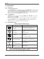
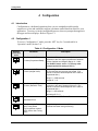
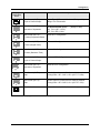
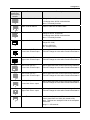
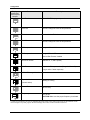
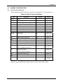
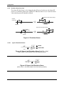
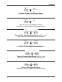
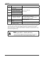
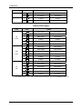
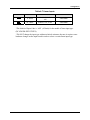
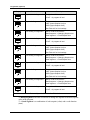
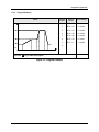
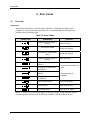
DC1000 Series
Digital Controller
Product Manual
51-52-25-113
August 2005
Industrial Measurement and Control
Copyright, Notices and Trademarks
Printed in Taiwan - © Copyright 2005 by Honeywell
Revison 1 - August 2005
WARRANTY/REMEDY
Honeywell warrants goods of its manufacture as being free of defective materials and faulty
workmanship. Contact your local sales office for warranty information. If warranted goods are
returned to Honeywell during the period of coverage, Honeywell will repair or replace without charge
those items it finds defective. The foregoing is Buyer's sole remedy and is in lieu of all other
warranties, expressed or implied, including those of merchantability and fitness for a
particular purpose. Specifications may change without notice. The information we supply is
believed to be accurate and reliable as of this printing. However, we assume no responsibility for its
use.
While we provide application assistance personally, through our literature and the Honeywell web
site, it is up to the customer to determine the suitability of the product in the application.
Industrial Measurement and Control
Honeywell Korea
191 HanGangRo 2ga, YongSanGu
Seoul, Korea
ii
DC1010/1020/1030/1040 Product Manual
8/05
About This Document
Abstract
This document provides descriptions and procedures for the Installation, Configuration, and Operation of your DC1000
Controller.
Contacts
World Wide Web
The following lists Honeywell’s World Wide Web sites that will be of interest to our customers.
Honeywell Organization
WWW Address (URL)
Corporate
http://www.honeywell.com
Industrial Measurement and Control
http://www.honeywell.com/imc
Telephone
Contact us by telephone at the numbers listed below.
Organization
Phone Number
United States and Canada
Honeywell
1-800-423-9883
1-800-525-7439
Asia Pacific
Asia Pacific Headquarters
(63-2) 633 2830
Europe
Honeywell PACE, Brussels, Belgium
Contact your Local Sales Office
Latin America
Honeywell, Ft. Washington, PA U.S.A.
215-641-3610
8/05
DC1010/1020/1030/1040 Product Manual
Tech. Support
Service
iii
Introduction
Symbol Definitions
The following table lists those symbols used in this document to denote certain conditions.
Symbol
Definition
This CAUTION symbol on the equipment refers the user to the Product Manual for
additional information. This symbol appears next to required information in the manual.
WARNING
PERSONAL INJURY: Risk of electrical shock. This symbol warns the user of a
potential shock hazard where HAZARDOUS LIVE voltages greater than 30 Vrms, 42.4
Vpeak, or 60 VDC may be accessible. Failure to comply with these instructions
could result in death or serious injury.
ATTENTION, Electrostatic Discharge (ESD) hazards. Observe precautions for
handling electrostatic sensitive devices
Protective Earth (PE) terminal. Provided for connection of the protective earth (green
or green/yellow) supply system conductor.
Functional earth terminal. Used for non-safety purposes such as noise immunity
improvement. NOTE: This connection shall be bonded to protective earth at the source
of supply in accordance with national local electrical code requirements.
Earth Ground. Functional earth connection. NOTE: This connection shall be bonded to
Protective earth at the source of supply in accordance with national and local electrical
code requirements.
Chassis Ground. Identifies a connection to the chassis or frame of the equipment shall
be bonded to Protective Earth at the source of supply in accordance with national and
local electrical code requirements.
Equipment protected throughout by DOUBLE INSULATION or REINFORCED
INSULATION
iv
DC1010/1020/1030/1040 Product Manual
8/05
Introduction
Contents
1
INTRODUCTION ................................................................................................... 1
1.1
2
Overview.........................................................................................................................................1
INSTALLATION..................................................................................................... 3
2.1
Overview.........................................................................................................................................3
2.2
Condensed Specifications ...............................................................................................................4
2.3
Model Number Interpretation .........................................................................................................6
2.4
Mounting.........................................................................................................................................8
2.4.1 Physical Considerations .......................................................................................................8
2.4.2 Overall Dimensions..............................................................................................................8
2.4.3 Mounting Procedure...........................................................................................................10
2.5
Wiring ...........................................................................................................................................11
2.5.1 Electrical Considerations ...................................................................................................11
2.6
Wiring Diagrams...........................................................................................................................12
2.6.1 Identify Your Wiring Requirements ..................................................................................12
2.6.2 Making Terminal Connections...........................................................................................12
2.6.3 Wiring Diagrams................................................................................................................13
3
OPERATION........................................................................................................ 17
3.1
Overview.......................................................................................................................................17
3.2
Operator Interface Overview ........................................................................................................17
3.2.1 Displays, LEDs, and Keys .................................................................................................18
3.3
Mode Access.................................................................................................................................19
3.3.1 How to move from one mode to another............................................................................19
3.4
Operation Mode ............................................................................................................................20
3.4.1 Key Functions ....................................................................................................................20
3.4.2 Operation Mode Prompts ...................................................................................................20
3.4.3 Control Types.....................................................................................................................21
3.4.4 Set Point .............................................................................................................................22
3.4.5 Alarm Functions and Associated Prompts .........................................................................23
4
CONFIGURATION............................................................................................... 24
4.1
Introduction...................................................................................................................................24
4.2
Configuration 1 .............................................................................................................................24
4.2.1 Configuration 2 ..................................................................................................................26
4.3
ALARMS CONFIGURATION ....................................................................................................29
4.3.1 Alarm Function Selections.................................................................................................29
4.3.2 Deviation Alarm Overview ................................................................................................30
4.3.3 Absolute Value Alarm Overview.......................................................................................32
4.3.4 Program Alarm...................................................................................................................33
8/05
DC1010/1020/1030/1040 Product Manual
v
Introduction
4.3.5
System Alarm.....................................................................................................................33
4.4
Function Lock ...............................................................................................................................34
4.5
Parameter Display Set (Hide or Display)......................................................................................35
4.5.1 Overview............................................................................................................................35
4.5.2 Functions of SETs..............................................................................................................35
4.6
Input Codes ...................................................................................................................................37
4.6.1 Code Selection ...................................................................................................................37
5
PROGRAMMER (OPTIONAL) ............................................................................ 41
5.1
Overview.......................................................................................................................................41
5.1.1 Introduction........................................................................................................................41
5.2
Programmer Terminologies ..........................................................................................................41
5.3
Operating Key Functions ..............................................................................................................41
5.4
Program Functions ........................................................................................................................41
5.4.1 Program Running Alarm ....................................................................................................41
5.4.2 Segment Completion Alarm...............................................................................................42
5.4.3 END Function ....................................................................................................................42
5.4.4 Linking Function................................................................................................................42
5.4.5 Wait Function.....................................................................................................................42
5.4.6 Other Functions..................................................................................................................43
5.5
Program Configuration Prompts ...................................................................................................44
5.5.1 Overview............................................................................................................................44
5.5.2 Configuration .....................................................................................................................44
5.5.3 Program Example...............................................................................................................47
6
ERROR CODES .................................................................................................. 48
6.1
Overview.......................................................................................................................................48
7
INDEX .................................................................................................................. 49
vi
DC1010/1020/1030/1040 Product Manual
8/05
Introduction
Tables
Table 2-1 Condensed Specifications _____________________________________________________ 4
Table 3-1 Displays, LEDs, and Keys ____________________________________________________ 18
Table 3-2 Mode Change Instructions ____________________________________________________ 19
Table 3-3 Operation Mode Prompts _____________________________________________________ 20
Table 4-1 Configuration 1 Mode________________________________________________________ 24
Table 4-2 Configuration 2 Mode________________________________________________________ 26
Table 4-3 Alarm Function Selections ____________________________________________________ 29
Table 4-4 Functions of Sets____________________________________________________________ 35
Table 4-5 Thermocouple Inputs ________________________________________________________ 37
Table 4-6 RTD Inputs ________________________________________________________________ 38
Table 4-7 Linear Inputs _______________________________________________________________ 39
Table 5-1 Key Functions ______________________________________________________________ 41
Table 5-2 Associated Program Functions _________________________________________________ 43
Table 5-3 Program Configuration Prompts ________________________________________________ 44
Table 6-1 Error Codes ________________________________________________________________ 48
8/05
DC1010/1020/1030/1040 Product Manual
vii
Introduction
Figures
Figure 2-1 Model DC1010 Dimensions ___________________________________________________ 8
Figure 2-2 Model DC1020 Dimensions ___________________________________________________ 8
Figure 2-3 Model DC1030 Dimensions ___________________________________________________ 9
Figure 2-4 Model DC1040 Dimensions ___________________________________________________ 9
Figure 2-5 Mounting Procedure ________________________________________________________ 10
Figure 2-6 Model DC1010 Wiring ______________________________________________________ 13
Figure 2-7 Model DC1020, DC1025 Wiring ______________________________________________ 14
Figure 2-8 Model DC1030 Wiring ______________________________________________________ 15
Figure 2-9 Model DC1040 Wiring ______________________________________________________ 16
Figure 3-1 Operator Interface __________________________________________________________ 17
Figure 3-2 Mode Access Diagram_______________________________________________________ 19
Figure 4-1 Deviation Alarms___________________________________________________________ 30
Figure 4-2 Upper Limit Deviation Alarm (Alarm Code 01, Alarm release in the first alarming situation) ___ 30
Figure 4-3 Upper Limit Deviation Alarm (Alarm Code 11, No alarm release in the first alarming situation) _ 30
Figure 4-4 Lower Limit Deviation Alarm (Alarm Code 02, Alarm release in the first alarming situation) ___ 31
Figure 4-5 Lower Limit Deviation Alarm (Alarm Code 12, No alarm release in the first alarming situation) _ 31
Figure 4-6 Dev. Band Breakaway Alarm (Alarm Code 03, Alarm release in the first alarming situation) ____ 31
Figure 4-7 Dev. Band Breakaway Alarm (Alarm Code 13, No alarm release in the first alarming situation) __ 31
Figure 4-8 Deviation Band Alarm (Alarm Code 04, Alarm release in the first alarming situation) _________ 31
Figure 4-9 Deviation Band Alarm (Alarm Code 14, No alarm release in the first alarming situation) _______ 31
Figure 4-10 Absolute Value Alarm ______________________________________________________ 32
Figure 4-11 Absolute Upper Limit Alarm (Alarm Code 05, Alarm release in the first alarming situation) ___ 32
Figure 4-12 Absolute Upper Limit Alarm (Alarm Code 15, No alarm release in the first alarming situation) _ 32
Figure 4-13 Absolute Lower Limit Alarm (Alarm Code 06, Alarm release in the first alarming situation)___ 32
Figure 4-14 Absolute Lower Limit Alarm (Alarm Code 16, No alarm release in the first alarming situation) 32
Figure 4-15 Program RUN Alarm – Code 17 ______________________________________________ 33
Figure 4-16 System Error Alarm – Code 08 _______________________________________________ 33
Figure 4-17 System Error Alarm – Code 18 _______________________________________________ 33
Figure 4-18 Display Status ____________________________________________________________ 35
Figure 5-1 Program Example __________________________________________________________ 47
viii
DC1010/1020/1030/1040 Product Manual
8/05
Introduction
1 Introduction
1.1
Overview
Function
The DC1000 family of microprocessor-based controllers combine a high degree of
functionality and reliability in 4 different formats: 1/16 DIN, 1/8 DIN, 3/16 DIN, and 1/4
DIN.
With a typical accuracy of ± 0.5% of span, the DC1000 is an ideal controller for
regulating temperature and other process variables in a variety of applications including
dryers, semiconductor packaging & testing, plastic processing, packaging machinery,
painting & coating, and climatic chambers.
Easy to Configure
Two different configuration levels provide easy access to parameters. A 4-digit security
code prevents unauthorized changes. Parameters can also be hidden to the user to prevent
unauthorized configuration of the unit.
Various Control Algorithms
The DC1000 series of controllers provides several different algorithms:
•
•
•
•
•
PID or ON/OFF Control
Hear/Cool Algorithms with 2 different PID sets
Motor Position Control without slidewire feedback
Single Phase Control with/without zero crossover control
Three Phase Control with/without zero crossover control
Mount Anywhere
The DC1000 controller family is industrial control equipment that must be panel
mounted. The wiring terminals must be enclosed within the panel. The DC1000 is
environmentally hardened and, when suitably enclosed, can be mounted virtually
anywhere in a plant or factory; on a wall, in a panel, or even on the process machine. It
withstands ambient temperature of up to 50°C (122°F).
8/05
DC1010/1020/1030/1040 Product Manual
1
Introduction
CE Conformity (Europe)
This product is in conformity with the protection requirements of the following:
European Council Directive; 73/23/EEC - the Low Voltage Directive, and 89/336/EEC the EMC Directive. Conformity of this product with any other “CE Mark” Directive(s)
shall not be assumed.
Enclosure Rating: Panel-mounted equipment, IP00. This controller must be panel
mounted. Terminals must be enclosed within panel. Front panel IP65 (IEC 529)
optionally.
2
DC1010/1020/1030/1040 Product Manual
8/05
Installation
2 Installation
2.1
Overview
Introduction
Installation of the DC1000 consists of mounting and wiring the controller according to
the instructions given in this section. Read the pre-installation information, check the
model number interpretation (Subsection 2.3), and become familiar with your model
selections, then proceed with installation.
CAUTION
Installation should be performed only by personnel who are technically competent to do
so. Local Regulations regarding electrical & safety must be observed.
Pre-installation Information
If the controller has not been removed from its shipping carton, inspect the carton for
damage then remove the controller.
8/05
•
Inspect the unit for any obvious shipping damage and report any damage due to
transit to the carrier.
•
Make sure a bag containing mounting hardware is included in the carton with the
controller.
•
Check that the model number shown on the inside of the case agrees with what you
have ordered.
DC1010/1020/1030/1040 Product Manual
3
Installation
2.2
Condensed Specifications
Honeywell recommends that you review and adhere to the operating limits listed in Table
2-1 when you install your controller.
Table 2-1 Condensed Specifications
TECHNICAL DATA
TC (K, J, R, S, B, E, N, T, W, PL II, U, L)
Type of Input
RTD (Pt100Ω, JPt100Ω, JPt50Ω)
PV Input
Indication
Control Mode
Output
Alarm
Aux. Output
nd
2
Input
(RSP)
Program
Communication
Linear (4 – 20mA)
Input Sampling Time
500 ms
Input Resolution
14 bit (each)
PV/SP Indication
4-digit, 7 segment display
Constant Value Storage
System
Non-volatile memory (EEPROM)
Indication Accuracy
± 0.5%FS
Proportional Band (P)
0~200% (On/Off action at P=0)
Integral Time (I)
0~3600 sec (PD action at I=0)
Derivative Time (D)
0~900 sec (PI action at D=0)
Cycle Time
0~150 sec (4~20mAÆ 0, SSRÆ1, relayÆ10)
Relay Output
Contact, SPST(DC1010)/SPDT(1020,1030,1040), 3A/240VAC
Voltage Output
Voltage Pulse, 20VDC/20mA
Linear Output
4~20mA, 0~5V, 0~10V, 1~5V, 2~10V
Motor Control Output
Three Position Step Control (Time proportional motor control)
Others
1ϕ SSR, 3ϕ SSR, 1ϕ SCR, 3ϕ SCR
Channel
3 channels (optional)
Mode
17 alarm mode available
Timer
Flicker alarm, continued alarm, on delay timer alarm
Output Signal
SP, PV
Type of Output
4~20mA, 0~20mA, 0~5V, 0~10V, 1~5V, 2~10V
Type of Input
4~20mA, 0~20mA, 0~5V, 0~10V, 1~5V, 2~10V
Sampling Time
500 ms
Pattern/Segment
2 pattern/ 8 segment (each)
Availability
Pattern link & repeat, program/segment end alarm
Type of Communication
RS-232, RS-485
Rated Power Supply
Voltage & Frequency
4
AC 100-240V, 50/60Hz or DC15-50V, 4VA
General
Power Consumption
Max. 8VA
Specifications
Storage Temperature
-25°C~65°C
Ambient Temperature
0°C~50°C
Ambient Humidity
50~85% RH (no condensation)
DC1010/1020/1030/1040 Product Manual
8/05
Installation
INPUT ACTUATIONS
TC
RTD
Linear
8/05
K
0.0~200.0, 400.0, 600, 800, 1000, 1200 °C
J
0.0~200.0, 400.0, 600, 800, 1000, 1200 °C
R
0.0~1600, 1769 °C
S
0.0~1600, 1769 °C
B
0.0~1820 °C
E
0.0~800, 1000 °C
N
0.0~1200,1300 °C
T
0.0~400.0, 200.0 °C, 0.0~350.0 °C
W
0.0~2000, 2320 °C
PL II
0.0~1300, 1390 °C
U
-199.9~600.0, 200.0 °C, 0.0~400.0 °C
L
0.0~400.0, 800.0 °C
Pt100
-199.9~600.0, 400.0, 200.0 °C, 0.0~200.0, 400.0, 600.0 °C
JPt100
-199.9~600.0, 400.0, 200.0 °C, 0.0~200.0, 400.0, 600.0 °C
JPt50
-199.9~600.0, 400.0, 200.0 °C, 0.0~200.0, 400.0, 600.0 °C
AN4
0~50mV
0~20mA, 0~1V, 0~5V, 0~10V
AN5
10~50mV
4~20mA, 1~5V, 2~10V
DC1010/1020/1030/1040 Product Manual
5
Installation
2.3
Model Number Interpretation
Introduction
Write your controller’s model number in the spaces provided below and circle the corresponding
items in each table. This information will also be useful when you wire your controller.
Instructions
Select the desired Key Number. The arrow to the right marks the selections available.
Make one selection each from Tables I through III using the column below the proper arrow.
A dot ( ) denotes unrestricted availability. A letter denotes restricted availability.
Key Numbers
I
II
I
II
DC10_ _ _ _ - _ _ _ - _ _ _ - _
KEY NUMBER
Description
Size
Power
Program
Input
Selection
48 x 48 mm (DIN) 1/16)
DC1010_ _
48 x 96 mm (DIN 1/8)
DC1020_ _
72 x 72 mm
DC1030_ _
96 x 96 (DIN 1/4)
DC1040_ _
90-240 Vac Power
DC10_0_ _
15-50 Vdc Power
DC10_1_ _
90-240 Vac Power / IP 65
DC10_2_ _
15-50 Vac Power / IP65
DC10_3_ _
90-240 Vac Power / UL Agency Approval
DC10_4_ _
15-50 Vdc Power / UL Agency Approval
DC10_5_ _
None
DC10_ _C_
Program (2 patterns, 8 segments per 1 pattern)
DC10_ _P_
RTD
DC10_ _ _R
TC
DC10_ _ _T
Linear
DC10_ _ _L
Availability
b
b
b
b
b
b
b
b
b
b
b
b
c
d
c
g
j
TABLE I
Control Output 1 None
1__
Volt, Voltage Pulse, 20VDC / 20 mA
2__
mA Current, 4-20mA
3__
Open loop circuit servo motor control
7__
0-5 V
A__
0-10 V
B__
1-5 V
C__
2-10 V
D__
Control Output 2 None
_0_
(Heat/Cool)
Relay, Contact, SPDT, 3A / 240VAC
_1_
Volt, Voltage Pulse, 20VDC / 20mA
_2_
Alarm Event
6
0__
Relay, Contact, SPDT, 3A / 240 VAC
mA Current, 4-20mA
_3_
0-5V
_A_
0-10V
_B_
1-5V
_C_
2-10V
_D_
1 Alarm Relay
__1
e
2 Alarm Relays
__2
f
3 Alarm Relays
__3
DC1010/1020/1030/1040 Product Manual
i
h
k
8/05
Installation
Availability
DC10_ _ _ _ 10
Table II
20 30 40
Selection
Transmitter
Remote SP
Communication
None
0__
4-20 mA
1__
0-20 mA
2__
0-5 V
A__
0-10 V
B__
1-5 V
C__
2-10 V
D__
None
_0_
4-20 mA
_1_
l
l
l
0-20 mA
_2_
l
l
l
0-5 V
_A_
l
l
l
0-10 V
_B_
l
l
l
1-5 V
_C_
l
l
l
2-10 V
_D_
l
l
l
None
__0
RS-232
__1
m n
RS-485
__2
m n
TABLE III
Manual
English
E
Chinese
C
French
F
Korean
K
RESTRICTIONS / NOTES
Restriction
Letter
Available Only With
Table
Selection
b
c
I
_ 0 1, _ 0 2
d
I & II
DC10 _ _ _ _ - _ 0 1 - _ 0 _ - _
Not Available With
Table
Selection
II
X__
e
I & II
DC10_ _ _ _ - _ X _ - 0 _ 2 - _
f
I & II
DC10_ _ _ _ - _ X _ - X _ 0 - _
g
I & II
DC10_ _ _ _ - _ X _ - X _ _ - _
II
X_X
I & II
DC10_ _ _ _ - _ X _ - _ X _ - _
h
I & II
DC10_ _ _ _ - _ 0 _ - 0 _ 0 - _
j
I & II
DC10_ _ _ _ - _ 0 _ - _ 0 _ - _
k
I & II
DC10_ _ _ _ - _ 0 _ - _ _ 0 - _
i
l
DC10_ _ _ P
m
II
X__
n
II
_X_
* X : Option Selected
0 : Option Not Selected
8/05
DC1010/1020/1030/1040 Product Manual
7
Installation
2.4
2.4.1
Mounting
Physical Considerations
The controller can be mounted on either a vertical or tilted panel using the mounting
bracket supplied. Adequate access space must be available at the back of the panel for
installation and servicing activities.
•
2.4.2
Overall dimensions and panel cutout requirements for mounting the controller are
shown in Figure 2-1 through.Figure 2-4
Overall Dimensions
Figure 2-1 Model DC1010 Dimensions
Figure 2-2 Model DC1020 Dimensions
8
DC1010/1020/1030/1040 Product Manual
8/05
Installation
Figure 2-3 Model DC1030 Dimensions
Figure 2-4 Model DC1040 Dimensions
8/05
DC1010/1020/1030/1040 Product Manual
9
Installation
2.4.3
Mounting Procedure
Before mounting the controller, refer to the nameplate on the outside of the case and
make a note of the model number. It will help later when selecting the proper wiring
configuration.
d
e
c
1. Put the mounting bracket in
the rail on the top & bottom
of the case.
2. Bend the grip of the bracket
& slide the bracket along
the rail until the case is
secured against the panel.
3. Put the grip of the bracket
on the groove to fasten the
case to the panel.
Side View
Figure 2-5 Mounting Procedure
10
DC1010/1020/1030/1040 Product Manual
8/05
Installation
2.5
2.5.1
Wiring
Electrical Considerations
Precautions
The controller is considered “rack and panel mounted equipment” per EN61010-1, Safety
Requirements for Electrical Equipment for Measurement, Control, and Laboratory Use,
Part 1: General Requirements. Conformity with 72/23/EEC, the Low Voltage Directive
requires the user to provide adequate protection against a shock hazard, The user shall
install this controller in an enclosure that prevents the OPERATOR access to the rear
terminals.
Mains Power Supply
This controller is suitable for connection to 100-240 Vac, 50/60 Hz or 15-50 Vdc, power
supply mains. It is the user’s responsibility to provide a switch and non-time delay (North
America), quick-acting, high breaking capacity, Type F(Europe), 1/2A, 250V fuse(s) or
circuit breaker for 100-240Vac operation as part of the installation. The switch or circuitbreaker should be located close to the controller, within easy reach of the operator. The
switch or circuit-breaker should be marked as the disconnecting device for the controller.
When applying power to multiple instruments, make sure that sufficient current is
supplied. Otherwise, the instruments may not start up normally due to the voltage drop
caused by the in-rush current.
Applying 100-240Vac to a controller rated for 15-50Vdc will severely damage
the controller and is a fire and smoke hazard
8/05
DC1010/1020/1030/1040 Product Manual
11
Installation
2.6
2.6.1
Wiring Diagrams
Identify Your Wiring Requirements
To determine the appropriate diagrams for wiring your controller, refer to the model
number interpretation in this section. The model number of the controller is on the
outside of the case.
Shielded twisted pair cable are required for all Analog I/O, Process Variable, RTD,
Thermocouple, dc millivolt, low level signal, mA, Digital Output, and computer interface
circuits.
2.6.2
Making Terminal Connections
(1) Connection of power supply input terminal
•
Type: Round
•
Cable square: 1.25 mm(0.049 in)
•
Diameter: 3.0 ~ 3.7 mm(0.118~ 0.145 in)
R1.5
1.25
5
Terminal with tube(R, 1.25 * M3)
•
12
Tighten the terminal screws using a torque between 0.8 N_ m or less.
DC1010/1020/1030/1040 Product Manual
8/05
Installation
2.6.3
Wiring Diagrams
N
Noise
Filter
POWER
1
L
2
AC 100 ~ 240V
(50 / 60Hz)
3
4
9
14
10
PV
OUTPUT
Relay Volt Linear
2
8
13
5
1
7
12
DC 15 ~ 50V
(option)
O U T2
6
11
2
3
3
Linear
O U T1=5
7
11 G 1
A,B,C ,D
Relay Volt Linear
4
1
2
3
TC
7
7
8
8
B
8
12 K1
13 G 2
O U T1
R TD
14 K2
9
B
9
9
10
A
10
10
ALARM
5
A,B,C ,D
AL1
AL1
AL2
2
11
13
3
12
14
O U T1=7
2
3 C LO SE
AUX. OUT
TRS
11
4 O PEN
COMM.
CO M M
RS232
RD
11
12
5 CO M
SD
SG
12
13
CO M M
RS485
D-
D+
11
12
13
Figure 2-6 Model DC1010 Wiring
8/05
DC1010/1020/1030/1040 Product Manual
13
Installation
L
1
11
2
12
3
13
4
14
5
15
6
16
7
17
8
18
9
19
10
20
Linear
R TD
Noise
Filter
POWER
N
AC 100 ~ 240V
(50 / 60Hz)
DC 15 ~ 50V
(option)
PV
OUTPUT
OUT2
6
R elay Volt Linear
1
2
3
17
TC
17
17
18
18
B
18
7
A,B ,C ,D
OUT1
19
B
19
19
20
A
20
20
R elay Volt Linear
8
9
NO1
2
3
NC
10 COM
ALARM
AL1
A,B ,C ,D
3
NC
AUX. OUT
AL2
NC
AL3
11
6
11
TRS
O U T1=7
6
4
NO
NO
5 COM
COM
12
7
12
13
13
7 C LO SE
8 O PEN
9
10 C O M
INPUT2
14
15
16
COMM.
COM M
RS232
RD
SD
SG
14
15
16
COM M
RS485
D-
D+
14
15
16
Figure 2-7 Model DC1020, DC1025 Wiring
14
DC1010/1020/1030/1040 Product Manual
8/05
Installation
L
Noise
Filter
POWER
N
AC 100 ~ 240V
(50 / 60Hz)
DC 15 ~ 50V
(option)
1
15
8
2
16
9
3
17
10
4
18
11
5
19
12
6
20
13
7
21
14
PV
OUTPUT
O U T2
3
Relay Volt Linear
1
2
3
4
A,B,C ,D
O U T1
Relay Volt Linear
5
6
NO1
2
3
Linear
O U T1=5
R TD
11
15 G 1
TC
11
11
12
12
B
12
17 G 2
19
13
B
13
13
14
A
14
14
PRO T
20
NC
7 COM
O U T1=7
ALARM
AL1
COM
3
A,B,C ,D
O U T1=8
3
15 G 1
4 C LO SE
16 K1
5 O PEN
17 G 2
6
18 K2
NO
4
8
18
9
19
NC 10
INPUT2
7 CO M
AUX. OUT
TRS
AL2
Rem ote SP
9
20
10
COMM.
CO M M
RS232
RD
SD
15
16
PRO T
21
SG
17
CO M M
RS485
D-
D+
15
16
17
Figure 2-8 Model DC1030 Wiring
8/05
DC1010/1020/1030/1040 Product Manual
15
Installation
L
Noise
Filter
POWER
N
1
31
11
COMM.
2
32
12
COMM
RS232
3
33
13
4
34
14
5
35
15
6
36
16
7
37
17
8
38
18
9
39
19
10
40
20
RD
AC 100 ~ 240V
(50 / 60Hz)
DC 15 ~ 50V
(option)
OUTPUT
OUT2
Relay Volt Linear
1
6
2
3
OUT1=6
31 RG
32 RG
OUT1
Relay Volt Linear
1
8 NO
2
3
9 NC
35 TG1
39
37 TG2
40
10
COM
OUT1=7
A,B,C,D
40
OUT1=8
33 G2
7 CLOSE
32 K1
34 K2
8 OPEN
33 G2
35 G3
9
10 COM
40
PV
INPUT
Linear
RTD
17
17
17
18
18
19
19
20
A
20
20
ALARM
AL1
AL2
AL3
4 NO
NO
7
5
NC 11
COM
14
39
6
12
COM
INPUT2
36 K3
35
13
COMM.
COMM
RS232
RD
14
15
SD
16
SG 16
15
COMM
RS485
D-
D+
14
15
16
PROT
PROT
36
B
Remote SP
34 K2
TC
19
3 NC
32 K1
31 G1
33
39
18
31 G1
6
32
D+
B
OUT1=9
PROT
32
TRS
PROT
39
31
D-
AUX. OUT
33 G2
2
A,B,C,D
31
SG 33
31 G1
1
7
OUT1=5
SD
COMM
RS485
40
Figure 2-9 Model DC1040 Wiring
16
DC1010/1020/1030/1040 Product Manual
8/05
Operation
3 Operation
3.1
Overview
This section gives you all the information necessary to help you monitor and operate your
controller including an Operator Interface overview, an explanation of the Displays, keys,
and LEDs, and Mode access, and Operation Modes.
3.2
Operator Interface Overview
Figure 3-1 is a view of the operator interface. See Table 3-1 for a description of Displays,
LEDs, and Keys.
Also, see section 4.5 to allow parameters to be hidden or diplayed.
Upper Display
Lower Display
LEDs
Bar Graph
SHIFT key
0%
20
40
60
80
100%
SET key
Up key
A/M key
Down key
Figure 3-1 Operator Interface
8/05
DC1010/1020/1030/1040 Product Manual
17
Operation
3.2.1
Displays, LEDs, and Keys
Table 3-1 Displays, LEDs, and Keys
Displays
Upper Display
4 digits dedicated to display the PV. In configuration mode, this display
indicates the name of a parameter.
Lower Display
4 digits dedicated to display the SP. In configuration mode, this display
indicates the value of a parameter or the status of the parameter selected
Bargraph
A 10 green LEDs’ bargraph indicates the value of the output in percentage
LEDs
Indications
OUT 1
Status of ‘Output 1’
OUT 2
Status of ‘Output 2’
AT
When the LED is ON, it indicates that the controller is doing automatic
tuning.
AL 1
Status of ‘Alarm 1’
AL 2
Status of ‘Alarm 2’
AL 3
Status of ‘Alarm 3’
MAN
When the LED is ON, it indicates that the controller is in manual mode.
PRO
When a program is running, the LED flickers
When a program is suspended, the LED is ON
When no program is running, the LED is OFF
Keys
SET
SET key allows moving from one parameter to another or saving a new
value of a parameter or the status of a parameter changed.
A/M
A/M key allows switching from automatic mode to manual mode or from
manual mode to automatic mode.
SHIFT
UP
DOWN
18
Function
SHIFT key allows shifting the digits to modify parameters.
Up key allows increasing the value of a digit selected or changing the
status of a parameter.
DOWN key allows decreasing the value of a digit selected or changing the
status of a parameter.
DC1010/1020/1030/1040 Product Manual
8/05
Operation
3.3
Mode Access
Operation
(1)
Configuration 1
(2)
(3)
Program
(2)
Configuration 2
(3)
Set Up
Figure 3-2 Mode Access Diagram
3.3.1
How to move from one mode to another
Refer to Figure 3-2 and Table 3-2 for instructions.
Table 3-2 Mode Change Instructions
Step
ATTENTION
8/05
Action
(1)
Press ‘SET’ key for 5 seconds, it grants access to
‘Configuration 1’ mode or return to ‘Operation’ mode from
‘Configuration 1’ mode.
(2)
Press ‘SHIFT’ key for 5 seconds while pressing ‘SET’ key first, it
grants access to ‘Configuration 2’ mode or return to ‘Operation’
mode.
(3)
All parameters related to program configuration will be displayed
next to parameters in ‘Operation’ mode. (* These parameters will
be shown in program model only)
Do not access ‘set up’ mode without technical assistance.
DC1010/1020/1030/1040 Product Manual
19
Operation
3.4
Operation Mode
3.4.1
3.4.1.1
Key Functions
Changing Parameter Value
Press the SHIFT KEY to change the parameters. If the SHIFT KEY is pressed, the first
digit begins blinking. Press the UP KEY or DOWN KEY to increase or decrease the
value of this digit, and then press the SHIFT KEY again to go to the next digit. As all
the digits are written, press SET KEY to enter the value.
3.4.1.2
Changing Modes
SET KEY also has the function of changing MODEs. If the SET KEY is pressed, the
display shows the next MODE.
If any key were not pressed for 1 minute, the display will return to Operation Mode.
Press the A/M KEY twice to go to Operation Mode, no matter what mode it’s in.
If OUTL is set to "0", it means the controller has no output.
3.4.2
Operation Mode Prompts
Table 3-3 Operation Mode Prompts
Displays
Parameter
PV Display
Description
To change the setpoint value, see changing
parameter values (paragraph 3.4.1.1).
SP Display
Press the “SET” key to save the value.
SET
Output Limit *
Percentage (%)
For limiting the maximum value of Control
Output
Range: 0 to 100%
SET
Auto Tuning
Default “NO”
Status
”“YES” = Auto Tune Starts
Alarm 1
Depending on the Alarm Function selected,
enter deviation value or absolute value.
SET
Value of Alarm Setpoint
See Section 4.3.1 Alarm Function Selections
SET
Alarm 2 **
Same as Alarm 1
Value of Alarm Setpoint
SET
Alarm 3 **
Same as Alarm 1
Value of Alarm Setpoint
Note: for programmer models, the prompts to configure the programs will
appear after the operation mode prompts. See Section 5
*The ‘OUTL’ is not shown in default mode
**AL2’ & ‘AL3’ are shown only in models with the relevant options.
20
DC1010/1020/1030/1040 Product Manual
8/05
Operation
3.4.3
3.4.3.1
Control Types
Manual Operation
In the manual mode, the operator directly controls the controller output level.
Press the “A/M”key until you see “OUTL” in the upper display and a fixed control
output value in the lower display.
SET
To change the value of the Output (%), refer to Paragraph 3.4.1.1 Changing Parameter
Value.
Press the “SET” key to save the value.
3.4.3.2
ON/OFF Control
ON/OFF is the simplest control type. The output can be either ON (100 %) or OFF (0
%). The Process Variable (PV) is compared with the setpoint (SP) to determine the sign
of the error (ERROR = PV–SP). The ON/OFF algorithm operates on the sign of the error
signal.
The output type must be the relay output (DC10X0XX-1XX-XXX-X).
See ‘Configuration 1” Mode (Table 4-1). Change ‘P’ value to 0. Until PV reaches SP, the
control output is just ON (100%), and then the control output becomes OFF (0%).
* To prevent the control ouput from flickering too frequently, set the hysteresis ‘HYS1’
in ‘Operation’ mode (Table 3-3).
3.4.3.3
PID Control
PID control is the default control type of this controller.
PID is normally used for three-mode control. This means that the output can be adjusted
somewhere between 100 % and 0 %. It applies all three control actions—Proportional
(P), Integral (I), and Derivative (D)—to the error signal.
See ‘Configuration 1” Mode (Table 4-1). Set the PID Values “P”, “I”, “D”, “db”, and
“CYC”.
Auto Tuning
See ‘Operation” Mode (Table 3-3). Set ‘AT’ prompt to ‘YES’. The auto tuning process
will start. After the auto tuning is completed, the controller gets optimum PID values for
the control system and starts the operation automatically.
Auto tuning allows the controller to automatically adjust the PID parameters, and is
suitable for use when temperature control is not accurate enough.
See ‘Configuration 1’ Mode (Table 4-1). Prompt ATVL = auto tuning offset. It will be
deducted from the Set Value [SV] (it can prevent overshoot during auto tuning)
SV-ATVL=Auto-tuning value, ATVL=auto tuning offset
8/05
DC1010/1020/1030/1040 Product Manual
21
Operation
Example:
SV=200ºC, ATVL=5, Auto tuning point is at 195ºC
During auto tuning the PV value will oscillate around 195ºC.
Hence the PV will not go over 200ºC.
Note: In programmable model, ATVL means Auto-tuning point
Auto tuning failure
Possible cause 1: ATVL is too big. (If not sure, set ATVL = 0)
Possible cause 2: System time is too long. (Set PID parameter manually)
Fuzzy
Fuzzy Overshoot Suppression: The fuzzy logic observes the speed and direction of the
PV signal as it approaches the setpoint and temporarily modifies the internal controller
response action as necessary to avoid an overshoot. There is no change to the PID
algorithm, and the fuzzy logic does not alter the PID tuning parameters.
See “Configuration 2” Mode (Table 4-2). Press the “A/M”key until you see:
SET
3.4.4
Select the “Fuzzy” code in the lower display.
Set Point
When power is applied, the default display is PV (Upper display) and Setpoint (Lower
display).
See ‘Operation” Mode (Table 3-3).
To change the setpoint value, see changing parameter values (paragraph 3.4.1.1).
Press the “SET” key to save the value.
22
DC1010/1020/1030/1040 Product Manual
8/05
Operation
3.4.5
Alarm Functions and Associated Prompts
Make sure each alarm is set properly.
8/05
•
See “Configuration 2” Mode (Table 4-2). Set the required Alarm Code in
prompts “Ald1”, “Ald2”, and “Ald3”.
Alarm Code: 00 to 19 (Table 4-3 Alarm Function Selections)
•
See “Configuration 2” Mode (Table 4-2). Define the Alarm timing required
for prompts “Alt1”, “Alt2”, and “Alt3”.
Range: 0-99 min, 59 seconds
0= flickering alarm, 99:59= continual alarm
Other = Time delay for alarm
•
See ‘Operation” Mode (Table 3-3). Enter the deviation value or absolute value
for prompts “Al1”, “Al2”, and “Al3” depending on the Alarm Code selected
above.
•
See “Configuration 2” Mode (Table 4-2). Set the hysteresis of alarms in
prompt “HYSA”.
DC1010/1020/1030/1040 Product Manual
23
Configuration
4 Configuration
4.1
Introduction
Configuration is a dedicated operation where you use straightforward keystroke
sequences to select and establish (configure) pertinent control data best suited for your
application. To assist you in the configuration process, there are prompts that appear in
the upper and lower displays. Refer to Figure 3-1
4.2
Configuration 1
To access ‘Configuration 1’ mode, press the ‘SET’ key for 5 seconds while in
‘Operation’ mode (Section 3.4)
Table 4-1 Configuration 1 Mode
Displays
Parameter
Description
Default Value
Shown
Main Control (OUT 1)
.
P Value (Proportional Band)
SET
Proportional - Regulates the controller’s output in
proportion to the error signal (the difference between
Process Variable and Setpoint).Range: 0 – 200%
[For On/Off Control, set P1 = 0. The only other
prompt required for setting is HYS 1]
Main Control (OUT 1)
SET
I Value (Integral Value)
Integral - Regulates the controller’s output to the size of
the error and the time the error has existed. (The
amount of corrective action depends on the value of
proportional Gain.)
Range: 0 – 3200 seconds
Integral off, I = 0
Main Control (OUT 1)
D Value (Derivative Time)
SET
Derivative – Regulates the controller’s output in
proportion to the rate of change of the error. (The
amount of corrective action depends on the value of
proportional Gain.)
Range: 0 – 900 seconds
Derivative off, D = 0
* DO NOT CHANGE THE VALUE
Main Control
SET
SET
24
Dead-Band Time
Main Control (OUT 1)
Range: 0 – Upper Limit Value (USPL)
Auto Tuning Offset
For Programmer modelsATVL means Auto Tuning
Point.
Prevents Overshoot during Autotuning
DC1010/1020/1030/1040 Product Manual
8/05
Configuration
Displays
Parameter
Description
Default Value
Shown
SET
SET
Main Control (OUT 1)
Output Type (SSR → 1, 4-20mA → 0, Relay → 10)
Cycle of Control Output
Range: 0 to 150 seconds
Main Control (OUT 1)
For On/Off Control (P1=0)
Actuation of Hysteresis
ON: PV<= (SP – HYS1)
OFF: PV> (SP + HYS1)
Sub Control (OUT 2) *
SET
SET
SET
Same as CYT1 Configuration
Cycle of Control Output
Sub Control (OUT 2) *
SET
Same as D1 Configuration
D Value (Derivative Time)
Sub Control (OUT 2) *
SET
Same as I1 Configuration
I Value (Integral Value)
Sub Control (OUT 2) *
SET
Same as P1 Configuration
P Value (Proportional Band)
Sub Control (OUT 2) *
SET
(Range 0-1000)
Same as HYS1 Configuration
Actuation of Hysteresis
Main Control (OUT 1)
Control Output is turned off before reaching setpoint
Gap
Turning Point = SP – GAP 1; Off = (OUT 1 = Heat)
Sub Control (OUT 2) *
Control Output is turned off before reaching setpoint
Gap
Turning Point = SP + GAP 2; On = (OUT 2 = Cool)
Function Lock
Refer to Section 4.4 for Mode access designations.
SET
* Will only appear in models with “OUT2” option.
8/05
DC1010/1020/1030/1040 Product Manual
25
Configuration
4.2.1
Configuration 2
To access ‘Configuration 2’ mode, press the ‘SHIFT’ key for 5 seconds WHILE pressing
‘SET’ key FIRST when in ‘Operation’ or ‘Configuration 1’ mode.
Table 4-2 Configuration 2 Mode
Displays
Parameter
Description
Default Value
shown except for
examples
I
Input 1 (INP1)
Defines the Input type and Input range
Selection (Code)
* Refer to Table 4-5, Table 4-6, and Table 4-7 for Input
Codes
Input 1 (INP1)
Used during calibration of linear input
* DO NOT change this value without technical
assistance
SET
example
Lower Limit of Linear input
SET
example
Input 1 (INP1)
Upper Limit of Linear input
Used during calibration of linear input
* DO NOT change this value without technical
assistance
SET
Decimal Point
Used to set the position of the decimal point.
Available for Linear Input only
Lower Setpoint Limit
For Example: Linear Input = 4-20mA, when 4mA(0%),
set the value for the lower limit
Upper Setpoint Limit
For Example: Linear Input = 4-20mA, when
20mA(100%), set the value for the upper limit
Input 2 (INP2)
Used during calibration of linear input
* DO NOT change this value without technical
assistance
SET
SET
SET
Lower Limit of Linear input
SET
Input 2 (INP2)
Upper Limit of Linear input
Used during calibration of linear input
* DO NOT change this value without technical
assistance
Alarm Code for Alarm 1
* Refer to Table 4-3 for Alarm Codes.
Time set for Alarm 1
* Range: 0-99 min, 59 seconds
SET
SET
0= flickering alarm, 99:59= continual alarm
Other = Time delay for alarm
SET
Alarm Code for Alarm 2
* Refer to Table 4-3 for Alarm Codes.
SET
26
DC1010/1020/1030/1040 Product Manual
8/05
Configuration
Displays
Parameter
Description
Default Value
shown except for
examples
Time set for Alarm 2
* Range: 0-99 min, 59 seconds
0= flickering alarm, 99:59= continual alarm
Other = Time delay for alarm
SET
Alarm Code for Alarm 3
* Refer to Table 4-3 for Alarm Codes.
Time set for Alarm 3
* Range: 0-99 min, 59 seconds
SET
0= flickering alarm, 99:59= continual alarm
Other = Time delay for alarm
SET
Hysteresis for alarms
SET
example
Sets the hysteresis for alarm actuation
(Range=0 to 1000)
ON: PV<=(SPHYS1)
OFF: PV>(SP+HYS1)
Main Control (OUT1) **0
Lower Limit of linear output
Used to adjust the linear control output during calibration
* DO NOT change the value without technical assistance
SET
example
Main Control (OUT1) **
Upper Limit of linear output
Used to adjust the linear control output during calibration
* DO NOT change the value without technical assistance
SET
example
Sub Control (OUT2) **
Lower Limit of linear output
Used to adjust the linear control output during calibration
* DO NOT change the value without technical assistance
SET
example
Sub Control (OUT2) **
Upper Limit of linear output
Used to adjust the linear control output during calibration
* DO NOT change the value without technical assistance
SET
example
Auxiliary Output
Lower Limit of Aux. output
Used to adjust the linear control output during calibration
* DO NOT change the value without technical assistance
SET
example
Auxiliary Output
Upper Limit of Aux. output
Used to adjust the linear control output during calibration
* DO NOT change the value without technical assistance
SET
Motor Time
SET
Three Position Step Control - This is the time it takes the
motor to travel from 0 to 100% (fully closed to fully
open). This time can usually be found on the nameplate
of the motor.
Range: 5 – 200 seconds
8/05
DC1010/1020/1030/1040 Product Manual
27
Configuration
Displays
Parameter
Description
Default Value
shown except for
examples
Wait Function
To set “WAIT” for program operation
Extra Set
DO NOT change the value of this parameter
ID Number
Communication ID Number
Baud Rate
DO NOT change the value of this parameter
SP Compensation
Range: -1000 to 1000
PV Compensation
Range: LSPL – USPL
SET
SET
SET
SET
SET
Used to Bias Process Variable
SET
Unit of PV and SP
Selection: C, F, and A (linear)
Soft Filter
Adjusts the PV response time (Range: 0.05 to 1.00)
SET
(Larger value = faster response)
SET
* DO NOT change this value
SET
Operation Mode
Heating or Cooling
(Control Action)
SET
Control Process
PID or Fuzzy
Frequency
50 or 60 Hz
SET
SET
CAUTION: Make sure the proper frequency is selected.
** These two parameters are only for adjusting the linear signal of the control output, not for the limitation of the
control output or any other purpose. DO NOT change these values without technical assistance.
28
DC1010/1020/1030/1040 Product Manual
8/05
Configuration
4.3
4.3.1
ALARMS CONFIGURATION
Alarm Function Selections
These Alarm Function Selections are entered in “Configuration 2”. See Section 4.2.1.
Table 4-3 Alarm Function Selections
Code
Description
Hold-ON
Refer to
00 / 10
None
01
Deviation high alarm
YES
Figure 4-2
11
Deviation high alarm
NO
Figure 4-3
02
Deviation low alarm
YES
Figure 4-4
12
Deviation low alarm
NO
Figure 4-5
03
Deviation high / low alarm
YES
Figure 4-6
13
Deviation high / low alarm
NO
Figure 4-7
04 / 14
Band alarm
NO
Figure 4-8
Figure 4-9
05
Absolute value high alarm
YES
Figure 4-11
15
Absolute value high alarm
NO
Figure 4-12
06
Absolute value low alarm
YES
Figure 4-13
16
Absolute value low alarm
NO
Figure 4-14
07
Segment end alarm
-
Paragraph
4.3.4.1
-
Figure 4-15
(Use for program model only)
17
Program run alarm
(Use for program model only)
08
System error alarm (On)
-
Figure 4-16
18
System error alarm (Off)
-
Figure 4-17
19
Soak timer
-
Paragraph
4.3.5.3
“Hold-On”(Blocking) means that the alarm does not work at the first time. The alarm
signal is suppressed until the parameter gets to the non-alarm limit or band.
8/05
DC1010/1020/1030/1040 Product Manual
29
Configuration
4.3.2
Deviation Alarm Overview
The Alarm SP (Set Point) is to be changed as the SP moves. In this case, the Alarm SP
preserves a certain deviation value with the SP. When an alarm is set, a certain deviation
value with the preset SP should be defined.
Alarm SP moves along SP change
Deviation
(Lower limit)
SP1
SP1
Alarm SP
SP Change
SP2
Alarm SP moves along SP change
Deviation
(Upper Limit)
SP1
SP1
Alarm SP
SP2
SP Change
Figure 4-1 Deviation Alarms
4.3.2.1
Types of Deviation Alarms
: Set Point
: Alarm Set Point
Figure 4-2 Upper Limit Deviation Alarm [Hold On = Yes]
(Alarm Code 01, Alarm release in the first alarming situation)
Figure 4-3 Upper Limit Deviation Alarm
(Alarm Code 11, No alarm release in the first alarming situation)
30
DC1010/1020/1030/1040 Product Manual
8/05
Configuration
Figure 4-4 Lower Limit Deviation Alarm
(Alarm Code 02, Alarm release in the first alarming situation)
Figure 4-5 Lower Limit Deviation Alarm
(Alarm Code 12, No alarm release in the first alarming situation)
Figure 4-6 Dev. Band Breakaway Alarm [Hold On = Yes]
(Alarm Code 03, Alarm release in the first alarming situation)
Figure 4-7 Dev. Band Breakaway Alarm
(Alarm Code 13, No alarm release in the first alarming situation)
Figure 4-8 Deviation Band Alarm [Hold On = Yes]
(Alarm Code 04, Alarm release in the first alarming situation)
Figure 4-9 Deviation Band Alarm
(Alarm Code 14, No alarm release in the first alarming situation)
8/05
DC1010/1020/1030/1040 Product Manual
31
Configuration
4.3.3
Absolute Value Alarm Overview
The Alarm SP (Set Point) is to be fixed even though the SP moves. When an alarm is set,
the absolute value of the Alarm SP should be defined.
Alarm Set Point (Fixed)
SP1
SP2
SP3
Figure 4-10 Absolute Value Alarm
4.3.3.1
Types of Absolute Value Alarms
Figure 4-11 Absolute Upper Limit Alarm [Hold On = Yes]
(Alarm Code 05, Alarm release in the first alarming situation)
Figure 4-12 Absolute Upper Limit Alarm
(Alarm Code 15, No alarm release in the first alarming situation)
Figure 4-13 Absolute Lower Limit Alarm
(Alarm Code 06, Alarm release in the first alarming situation)
Figure 4-14 Absolute Lower Limit Alarm
(Alarm Code 16, No alarm release in the first alarming situation)
32
DC1010/1020/1030/1040 Product Manual
8/05
Configuration
4.3.4
Program Alarm
4.3.4.1 Segment End Alarm (Alarm Code 07)
Once the selected segment is completed, the alarm becomes activated
- ALD1 – ALD3
Set the Alarm Code 07
- AL1 – AL3
Enter Segment No.for alarms
- ALT1 – ALT3
Define the alarm timing
(0= Flickering, 99.59 = Continuous, Others = Time Delay*)
* If ALD1-ALD3 is "07" (in other words, the alarm is set as "segment end alarm"), the ALT means how long
the alarm is enabled (activated immediately and last during specified time).
* In case ALD1 - ALD3 is not "07" (in other words, the alarm is not set as "segment end alarm"), the ALT
means "Time Delay".
4.3.4.2 Program RUN Alarm (Alarm Code 17)
While a program runs, the alarm becomes actuated
Figure 4-15 Program RUN Alarm – Code 17
4.3.5
System Alarm
4.3.5.1 System Error Alarm (Alarm Code 08)
Figure 4-16 System Error Alarm – Code 08
4.3.5.2 System Error Alarm (Alarm Code 18)
Figure 4-17 System Error Alarm – Code 18
4.3.5.3 Timer Alarm (Alarm Code 19)
Once the PV reaches the SP, the alarm becomes actuated after a certain time delay.
(Range: 00 hour 00 min – 99 hour 59 min)
8/05
DC1010/1020/1030/1040 Product Manual
33
Configuration
4.4
Function Lock
According to the status of the parameter “LCK” in ‘Configuration 1’ mode, ‘access to
modes’ and ‘change of values’ can be prohibited.
LCK=0000
MODE ACCESS-Access to ‘Operation’, Configuration1 & 2’
modes allowed (* Default)
LCK=0100
MODE ACCESS-Access to ‘Operation’ & ‘Configuration 1’
mode allowed
VALUE CHANGE-Every value change in each mode allowed
MODE ACCESS-Access to ‘Operation’ & ‘Configuration 1’
mode allowed
LCK=0110
VALUE CHANGE -Value changes only in ‘Operation’ mode
allowed
MODE ACCESS-Access to ‘Operation’ mode allowed
LCK=0001
VALUE CHANGE-Value change of SP (Set Point) allowed
only
LCK=1111
MODE ACCESS-Access to “Set Up” mode allowed
LCK=0101
All access & value changes prohibited except the change of
“LCK” status
CAUTION
Configuration should be performed only by personnel who are technically
competent to do so. Local Regulations regarding electrical & safety must be
observed.
34
DC1010/1020/1030/1040 Product Manual
8/05
Configuration
4.5
4.5.1
Parameter Display Set (Hide or Display)
Overview
You can choose to hide or display some parameters by selecting the set mode of each.
See Figure 4-18 Display Status for an interpretation of the Status of the Sets.
Refer to Table 4-4 for Functions of the Sets.
SET N0.
Press SET key to change SET 0 ~ 9
SET 1
0 1 0
0=Hide
1=Display
1
Status of SET # . 1
Status of SET # . 2
Status of SET # . 3
Status of SET # . 4
# = Set Number
Example: Set 1 - 0 1 0 1 = OUTL (Displayed), AT (Hidden), AL1 (Displayed), AL2 (Hidden)
Figure 4-18 Display Status
4.5.2
Functions of SETs
Table 4-4 Functions of Sets
Set
Number
8/05
Function
Set
Number
Function
1.1
OUTL
5.1
CLO2, CHO2
1.2
AT
5.2
CLO3, CHO3
1.3
AL1
5.3
RUCY,WAIT, SETA
1.4
AL2
5.4
IDNO, BAUD
2.1
AL3
6.1
SVOS (SP Comp = 0 or 1)
2.2
ANL1, ANH1, DP
6.2
PVOS (PV Comp = 0 or 1)
2.3
LSPL, USPL
6.3
UNIT
2.4
ANL2, ANH2
6.4
SOFT
3.1
ALD1
7.1
CASC
3.2
ALT1
7.2
OUD
3.3
ALD2
7.3
OPAD
3.4
ALY2
7.4
HZ
4.1
ALD3
4.2
ALT3
4.3
HYSA
4.4
CLO1, CHO1
DC1010/1020/1030/1040 Product Manual
35
Configuration
Set
Number
8.1
Function
Remarks
0 = Not repeat
1 = Program repeat
8.2
8.3
(Note 1)
0 = No power failure option
Programmer Model Only
1 = With power failure option
See Section 5.
0 = Program starts at 0
1 = Program starts from PV
8.4
DO NOT USE SET 8.4. SEE CAUTION BELOW
9.2
0 = Displays the Working SP
Varying value per time is displayed
1 = Displays the Target SP
For Programmer Models: 1 = The time unit is
changed from HH:MM to MM:SEC
9.3
TRS SV
9.4
TRS PV
0.3
0 = No remote SV option
Auxiliary Output Use
1 = Remote SV option
Note 1: When SET 8.3=1, the Programmer Controller will initiate the SV value to the
current PV value. It will be more energy efficient, and also decreases the time needed to
achieve the desired SV value. The remaining time left to reach the SV value will be
shown in the parameter “TIMR”. Hence the time of countdown is related to the PV value,
not related to segment setting.
CAUTION
DO NOT operate SET 8.4. – DO NOT set SET 8.4 to 1
The PV LED will not display any values and the process will be confused.
In this case, press the SHIFT key and change the setting to “XXX0”.
36
DC1010/1020/1030/1040 Product Manual
8/05
Configuration
4.6
Input Codes
4.6.1
Code Selection
It requires that the Input Code in ‘Configuration 2’ mode be selected properly before the
operation starts. See Section 4.2.1 [Parameters Input 1 (INP1) and Input 2 (INP2)]
Table 4-5 Thermocouple Inputs
TYPE
K
J
R
S
B
E
N
T
W
PLII
U
8/05
CODE
RANGE
0.0~200.0°C
0.0~392.0°F
0.0~400.0°C
0.0~752.0°F
0~600°C
0~1112°F
0~800°C
0~1472°F
0~1000°C
0~1832°F
0~1200°C
0~2192°F
0.0~200.0°C
0.0~392.0°F
0.0~400.0°C
0.0~752.0°F
0~600°C
0~1112°F
0~800°C
0~1472°F
0~1000°C
0~1832°F
0~1200°C
0~2192°F
0~1600°C
0~2912°F
0~1796°C
0~3216°F
0~1600°C
0~2912°F
0~1796°C
0~3216°F
0~1820°C
0~3308°F
0~800°C
0~1472°F
0~1000°C
0~1832°F
0~1200°C
0~2192°F
0~1300°C
0~2372°F
0.0~400.0°C
0.0~752.0°F
0.0~200.0°C
0.0~392.0°F
0.0~350.0°C
0.0~662.0°F
0~2000°C
0~3632°F
0~2320°C
0~2372°F
0~1300°C
0~2372°F
0~1390°C
0~2534°F
-199.9~600.0°C
-199.9~999.9°F
DC1010/1020/1030/1040 Product Manual
37
Configuration
TYPE
CODE
L
RANGE
-199.9~200.0°C
-199.9~392.0°F
0.0~400.0°C
0.0~752.0°F
0~400°C
0~752°F
0~800°C
0~1472°F
Table 4-6 RTD Inputs
TYPE
CODE
RANGE
-199.9~600.0°C
-199.9~999.9°F
-199.9~400.0°C
-199.9~752.0°F
JIS
-199.9~200.0°C
-199.9~392.0°F
Pt100
0~200°C
0~392°F
0~400°C
0~752°F
0~600°C
0~1112°F
-199.9~600.0°C
-199.9~999.9°F
-199.9~400.0°C
-199.9~752.0°F
DIN
-199.9~200.0°C
-199.9~392.0°F
Pt100
0~200°C
0~392°F
0~400°C
0~752°F
0~600°C
0~1112°F
-199.9~600.0°C
-199.9~999.9°F
-199.9~400.0°C
-199.9~752.0°F
JIS
-199.9~200.0°C
-199.9~392.0°F
Pt50
0~200°C
0~392°F
0~400°C
0~752°F
0~600°C
0~1112°F
* The default of Input Code is ‘DP3’ for the model of RTD input type. (DC10X0XR-XXX-XXX-X)
38
DC1010/1020/1030/1040 Product Manual
8/05
Configuration
Table 4-7 Linear Inputs
CODE
SIGNAL
INPUT TYPE
RANGE
0 - 50mV
0-20mA, 0-1V, 0-5V, 010V
-1999~9999
10 - 50mV
4-20mA, 1-5V, 2-10V
-1999~9999
*The default of Input Code is ‘AN5’ (4-20mA) for the model of linear input type.
(DC10X0XL-XXX-XXX-X)
* DO NOT change the input type without technical assistance because it requires some
hardware changes on the input board in order to select a certain linear input type.
8/05
DC1010/1020/1030/1040 Product Manual
39
Configuration
40
DC1010/1020/1030/1040 Product Manual
8/05
Programmer (Optional)
5 Programmer (Optional)
5.1
5.1.1
Overview
Introduction
The program function of DC1000 has 2 program patterns, and each program has Max. 8
segments. The programs can be linked for a continuous 16 segments.
The term “programming” is used here to identify the process for selecting and entering
the individual ramp and soak segment data needed to generate the required setpoint
versus time profile (also called a program).
A segment is a ramp or soak function which together make up a setpoint program.
Setpoint Ramp/Soak Programming lets you configure 8 ramp and 8 soak segments to be
stored for use as one program or several small programs. You designate the end segment
to determine where the program is to stop.
Each segment can be defined as a period of “RAMP” or “SOAK” status.
5.2
Programmer Terminologies
Program: A pattern which consists of some segments
Segment: A RAMP segment or a SOAK segment
RAMP: A segment with changing SP
SOAK: A Status with fixed SP
5.3
Operating Key Functions
Table 5-1 Key Functions
Key
Function
START
+ SET
+ SET
5.4
5.4.1
Description
Start a program, ‘PRO’ LED to be flickered during the
running operation.
WAIT
Suspend the running program. ‘PRO’ LED will be turned on.
JUMP
Skip a current segment.
RESET
Stop the program running. ‘PRO’ LED will be turned off
Program Functions
Program Running Alarm
ALD1 = 17
8/05
DC1010/1020/1030/1040 Product Manual
41
Programmer (Optional)
Alarm Operation: During the program running, Alarm 1 will become actuated
5.4.2
Segment Completion Alarm
ALD1 (Alarm Code for Alarm 1)= 07 (Segment End Alarm)
AL1 (Alarm Condition)= 2 (‘2’ means Segment No.) When segment 2 ends, AL1 will
act.
ALT1 (Alarm Time) = 00.10
Alarm Operation Example: Once Segment 2 is completed, Alarm 1 will become actuated
and will be on for 10 seconds
5.4.3
END Function
The DC1000 does not have an END segment, so that the program will complete all the
segments if segments are defined. If the program procedure is less than 8 segments, set
the ‘OUT’ of next segment to 0, then the program running will be ended right after the
previous segment is completed. Otherwise, it will proceed for 8 or 16 segments
5.4.4
Linking Function
The program function of DC1000 has 2 program patterns, and each program has a
maximum of 8 segments. You can link these two patterns to obtain a program of 16
segments (PTN = 0)
PTN=1 proceed pattern 1-contains 8 segments.
PTN=2 proceed pattern 2-contains 8 segments.
PTN=0 linking proceed pattern 1 and 2 - total 16 segments.*
(*Please configure PTN1 and PTN2 first, and then set PTN to 0 – See Table 5-3 Program
Configuration Prompts)
5.4.5
Wait Function
Refer to “Wait” in Table 4-2 for Setting.
Wait = 0
Wait = Others
No Wait
Program holds on WAIT state until PV > (SV – WAIT setting)
Example:
PV = 80
SV_1 = 100
WAIT = 2
When PV runs to 100 at segment 1, the program will hold until the PV > 98, then the
program will run to segment 2.
continued
42
DC1010/1020/1030/1040 Product Manual
8/05
Programmer (Optional)
5.4 Program Functions (continued)
5.4.6
Other Functions
These other functions [Program Repeat, Power Failure Option, and Program Start from
PV] are set through the SETS function (Refer to Table 4-4 Functions of Sets).
Table 5-2 Associated Program Functions
SET
8/05
Function
Remarks
8.1
0 = No Program Repeat
1 = Program Repeats
When SET 8.1 = 1, the program will repeat
from beginning to end.
8.2
0 = No Power Failure Option
1 = With Power Failure Option
When SET 8.2 = 1, if power is lost before
the “target” setpoint is reached, upon power
recovery, the controller powers up with
Setpoint = Current PV value and it
automatically “Restarts” from setpont =
current PV value up to the original “target”
setpoint.
8.3
0 = Program starts from 0
1 = Program starts from PV
When SET 8.3 = 1, the setpoint is set to the
current PV value and the Program then
starts from this value. The program will be
more energy efficient, and also decrease
the time needed to achieve the desired
setpoint value. The remaining time left to
reach the setpoint value will be shown in the
parameter “TIMR” (See Table 5-3 Program
Configuration Prompts). The time of
countdown in this instance is related to the
PV value, not the segment setting.
DC1010/1020/1030/1040 Product Manual
43
Programmer (Optional)
5.5
5.5.1
Program Configuration Prompts
Overview
The prompts to configure the programs will appear after the operation mode prompts. See
Table 3-3. Also see Table 5-2 for Associated program functions.
5.5.2
Configuration
Table 5-3 Program Configuration Prompts
Displays
Parameter
Description
Start from Operation Mode – See Table 3-3
SET
Program Pattern
Range: 0-2
PTN=1 proceed pattern 1-contains 8
segments.
PTN=2 proceed pattern 2-contains 8
segments.
SET
PTN=0 linking proceed pattern 1 and 2 - total
16 segments.
(Please set PTN1 and PTN2 at first, and then
set PTN to 0)
Program Segment Display
SET
Lower Display = Pattern# ― Segment#
Example shown: Pattern 1 ― Segment 1
Range: Pattern(1,2,0) ― Segment(1~8)
Program timer display
Range: 99hrs:59min
Refer to Table 4-4 Functions of Sets to set
the units of the Timer:
SET
SET 9.2 = 0
The unit of Timer is Hour:Minute
SET 9.2 = 1
The unit of Timer is Minutes:Seconds
Setpoint for Segment 1
SET
Range:
LSPL (Lower Setpoint Limit) to
USPL (Upper Setpoint Limit)
See Table 4-2 for Limit settings
Time Setting for Segment 1
Ramp segment* = Changing Setpoint time
Soak segment** = Fixed Setpoint time
SET
Output Limit for Segment 1
SET
44
Range: 0-99 hrs:59 minutes
Range: 0 to 100%
If OUT = 0, program will end
DC1010/1020/1030/1040 Product Manual
8/05
Programmer (Optional)
Displays
Parameter
Setpoint for Segment 2
SET
Description
Range:
LSPL (Lower Setpoint Limit) to
USPL (Upper Setpoint Limit)
See Table 4-2 for Limit settings
Time Setting for Segment 2
Range: 0-99 hrs:59 minutes
Ramp segment* = Changing Setpoint time
Soak segment** = Fixed Setpoint time
SET
Output Limit for Segment 2
Range: 0 to 100%
If OUT = 0, program will end
SET
Setpoint for Segment 3
SET
Range:
LSPL (Lower Setpoint Limit) to
USPL (Upper Setpoint Limit)
See Table 4-2 for Limit settings
Time Setting for Segment 3
Range: 0-99 hrs:59 minutes
Ramp segment* = Changing Setpoint time
Soak segment** = Fixed Setpoint time
SET
Output Limit for Segment 3
Range: 0 to 100%
If OUT = 0, program will end
SET
Setpoint for Segment 4
SET
Range:
LSPL (Lower Setpoint Limit) to
USPL (Upper Setpoint Limit)
See Table 4-2 for Limit settings
Time Setting for Segment 4
Range: 0-99 hrs:59 minutes
Ramp segment* = Changing Setpoint time
Soak segment** = Fixed Setpoint time
SET
Output Limit for Segment 4
Range: 0 to 100%
If OUT = 0, program will end
SET
Setpoint for Segment 5
SET
Range:
LSPL (Lower Setpoint Limit) to
USPL (Upper Setpoint Limit)
See Table 4-2 for Limit settings
Time Setting for Segment 5
SET
8/05
Range: 0-99 hrs:59 minutes
Ramp segment* = Changing Setpoint time
Soak segment** = Fixed Setpoint time
DC1010/1020/1030/1040 Product Manual
45
Programmer (Optional)
Displays
Parameter
Output Limit for Segment 5
Description
Range: 0 to 100%
If OUT = 0, program will end
SET
Setpoint for Segment 6
SET
Range:
LSPL (Lower Setpoint Limit) to
USPL (Upper Setpoint Limit)
See Table 4-2 for Limit settings
Time Setting for Segment 6
Range: 0-99 hrs:59 minutes
Ramp segment* = Changing Setpoint time
Soak segment** = Fixed Setpoint time
SET
Output Limit for Segment 6
Range: 0 to 100%
If OUT = 0, program will end
SET
Setpoint for Segment 7
SET
Range:
LSPL (Lower Setpoint Limit) to
USPL (Upper Setpoint Limit)
See Table 4-2 for Limit settings
Time Setting for Segment 7
Range: 0-99 hrs:59 minutes
Ramp segment* = Changing Setpoint time
Soak segment** = Fixed Setpoint time
SET
Output Limit for Segment 7
Range: 0 to 100%
If OUT = 0, program will end
SET
Setpoint for Segment 8
SET
Range:
LSPL (Lower Setpoint Limit) to
USPL (Upper Setpoint Limit)
See Table 4-2 for Limit settings
Time Setting for Segment 8
Ramp segment* = Changing Setpoint time
Soak segment** = Fixed Setpoint time
SET
Output Limit for Segment 8
SET
Range: 0-99 hrs:59 minutes
Range: 0 to 100%
If OUT = 0, program will end
Back to “Operation” Mode – See Table 3-3
*A Ramp Segment is the time it will take to change the setpoint to the next setpoint
value in the program.
** A Soak Segment is a combination of soak setpoint (value) and a soak duration
(time).
46
DC1010/1020/1030/1040 Product Manual
8/05
Programmer (Optional)
5.5.3
Program Example
Profile
90
50
20
Segment
Number
Setpoint
Values
Time Settings
1
SP 1 = 20
T 1 = 00:01
2
SP 2 = 50
T 2 = 09:00
3
SP 3 = 50
T 3 = 00:02
4
SP 4 = 90
T 4 = 00:02
5
SP 5 = 90
T 5 = 00:02
6
SP 6 = 20
T 6 = 00:01
7
SP 7 = 0
T 7 = 00:00
8
SP
Time
Press the
1
10
12 14
16 17
key to start the program.
Figure 5-1 Program Example
8/05
DC1010/1020/1030/1040 Product Manual
47
Error Codes
6 Error Codes
6.1
Overview
Introduction
Instrument performance can be adversely affected by installation and application
problems as well as by hardware problems. We recommend that you investigate the
problems in the following order:
Table 6-1 Error Codes
ERROR CODE
DESCRIPTION
Open the circuit of ‘INPUT 1’
(sensor)
A/D Convert Failure
(NOTE !)
(NOTE !)
SOLUTION
Check the wiring
Service Call required
Cold junction compensation
failure
Service Call required
Open the circuit of ‘INPUT 2’
(sensor)
Check the wiring
Excess of PV over upper limit
(INPUT 1)
Shortage of PV under lower
limt (INPUT1)
Excess of PV over upper limit
(INPUT2)
Shortage of PV under lower
limt (INPUT2)
- Check sensor wiring& input
code
- Adjust the range of
indication
Memory (RAM) failure
Service call required
Interface failure
Check wiring of input
Auto tuninig failure
Check wiring of output
NOTE 1: If one of these messages appear in the upper display of the controller, please
check the points as described in the Solution column or call for techincal service.
48
DC1010/1020/1030/1040 Product Manual
8/05
7 Index
H
A
Absolute Value Alarm Overview .......................... 32
Alarm 1.................................................................. 20
Alarm 2.................................................................. 20
Alarm 3.................................................................. 20
Alarm Code for Alarm 1........................................ 26
Alarm Code for Alarm 2........................................ 26
Alarm Code for Alarm 3........................................ 27
Alarm Function Selections .................................... 29
Alarm Functions .................................................... 23
Alarms Configuration ............................................ 29
Associated Program Functions .............................. 43
Auto Tuning .................................................... 20, 21
Auto Tuning Offset ............................................... 24
Auxiliary Output.............................................. 27, 36
B
Baud Rate .............................................................. 28
Blocking ................................................................ 29
C
CE Conformity (Europe) ......................................... 2
Changing Modes.................................................... 20
Changing Parameter Value.................................... 20
Communication ID Number .................................. 28
Configuration......................................................... 24
Configuration 1 Mode ........................................... 24
Configuration 2 Mode ........................................... 26
Control Algorithms.................................................. 1
Control Process...................................................... 28
Control Types ........................................................ 21
Cycle of Control Output ........................................ 25
D
Dead-Band Time ................................................... 24
Decimal Point ........................................................ 26
Derivative Time............................................... 24, 25
Deviation Alarm Overview ................................... 30
Dimensions .............................................................. 8
Display Status........................................................ 35
Displays, LEDs, and Keys..................................... 18
E
Electrical Considerations....................................... 11
END Function........................................................ 42
Error Codes............................................................ 48
F
Frequency .............................................................. 28
Functions of SETs ................................................. 35
Fuzzy Overshoot Suppression ............................... 22
G
Hysteresis .............................................................. 25
Hysteresis for alarms ............................................. 27
I,J
Input 1.................................................................... 26
Input 2.................................................................... 26
Input Codes............................................................ 37
Installation ............................................................... 3
Integral Value .................................................. 24, 25
K
Key Functions........................................................ 20
L
Linear Inputs.......................................................... 39
Linking Function ................................................... 42
Lock................................................................. 25, 34
Lower Limit of Aux. output .................................. 27
Lower Limit of Linear input.................................. 26
Lower Limit of linear output ................................. 27
M,N
Main Control (OUT 1)........................................... 24
Main Control (OUT1)............................................ 27
Mains Power Supply.............................................. 11
Manual Operation.................................................. 21
Mode Access ......................................................... 19
Mode Change Instructions..................................... 19
Model DC1010 Dimensions .................................... 8
Model DC1010 Wiring.......................................... 13
Model DC1020 Dimensions .................................... 8
Model DC1020, DC1025 Wiring .......................... 14
Model DC1030 Dimensions .................................... 9
Model DC1030 Wiring.......................................... 15
Model DC1040 Dimensions .................................... 9
Model DC1040 Wiring.......................................... 16
Model Number Interpretation.................................. 6
Motor Time............................................................ 27
Mounting ................................................................. 8
Mounting Procedure .............................................. 10
O
ON/OFF Control.................................................... 21
Operating Key Functions....................................... 41
Operation ............................................................... 17
Operation Mode............................................... 20, 28
Operation Mode Prompts ...................................... 20
Operator Interface Overview ................................. 17
Output Limit .......................................................... 20
Output Limit for Segment...................................... 44
Overview ................................................................. 1
Gap ........................................................................ 25
8/05
DC1010/1020/1030/1040 Product Manual
49
P,Q
S
Parameter Display Set (Hide or Display) .............. 35
Physical Considerations........................................... 8
PID Control ........................................................... 21
Power Failure Option ............................................ 43
Pre-installation Information..................................... 3
Program Alarm ...................................................... 33
Program Configuration Prompts............................ 44
Program Example .................................................. 47
Program Functions................................................. 42
Program Pattern ..................................................... 44
Program Repeat ..................................................... 43
Program Repeats.................................................... 43
Program RUN Alarm............................................. 33
Program Running Alarm ....................................... 42
Program Segment Display ..................................... 44
Program Start from PV .......................................... 43
Program starts from PV ......................................... 43
Program timer display ........................................... 44
Programmer ........................................................... 36
Programmer (Optional).......................................... 41
Programmer Terminologies ................................... 41
Proportional Band............................................ 24, 25
PV Compensation.................................................. 28
PV Display ............................................................ 20
Segment Completion Alarm .................................. 42
Segment End Alarm............................................... 33
Set Point ................................................................ 22
Setpoint for Segment ............................................. 44
Setpoint Limit........................................................ 26
Soak Segment ........................................................ 46
Soft Filter............................................................... 28
SP Compensation................................................... 28
SP Display ............................................................. 20
Specifications .......................................................... 4
System Alarm ........................................................ 33
System Error Alarm............................................... 33
R
Ramp Segment....................................................... 46
RTD Inputs ............................................................ 38
T
Terminal Connections............................................ 12
Thermocouple Inputs............................................. 37
Three Position Step Control .................................. 27
Time set for Alarm 1 ............................................. 26
Time set for Alarm 2 ............................................. 27
Time set for Alarm 3 ............................................. 27
Time Setting for Segment...................................... 44
Timer Alarm .......................................................... 33
Types of Absolute Value Alarms .......................... 32
Types of Deviation Alarms.................................... 30
U,V
Upper Limit of Aux. output................................... 27
Upper Limit of Linear input .................................. 26
W,X,Y,Z
Wait Function .................................................. 28, 42
Wiring.................................................................... 11
Wiring Diagrams ................................................... 12
50
DC1010/1020/1030/1040 Product Manual
8/05
Industrial Measurement and Control
Honeywell Korea
191 HanGangRo 2ga, YongSanGu
Seoul, Korea
51-52-25-113 Rev. 1 0805 Printed in Korea