1
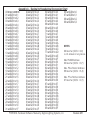
Appendix A - Decimal to Hexadecimal Conversion Chart
64 set S2,S1 to 4,0
00 INVALID ADDRESS
32 set S2,S1 to 2,0
96 set S2,SI to 6,0
65 set S2,S1 to 4,1
01 set S2,S1 to 0,1
33 set S2,S1 to 2,1
97 set S2,SI to 6,1
66 set S2,S1 to 4,2
02 set S2,S1 to 0,2
34 set S2,S1 to 2,2
98 set S2,SI to 6,2
67 set S2,S1 to 4,3
03 set S2,S1 to 0,3
35 set S2,S1 to 2,3
99 set S2,SI to 6,3
68 set S2,S1 to 4,4
04 set S2,S1 to 0,4
36 set S2,S1 to 2,4
69 set S2,S1 to 4,5
05 set S2,S1 to 0,5
37 set S2,S1 to 2,5
70 set S2,S1 to 4,6
06 set S2,S1 to 0,6
38 set S2,S1 to 2,6
71 set S2,S1 to 4,7
07 set S2,S1 to 0,7
39 set S2,S1 to 2,7
72 set S2,S1 to 4,8
08 set S2,S1 to 0,8
40 set S2,S1 to 2,8
73 set S2,S1 to 4,9
09 set S2,S1 to 0,9
41 set S2,S1 to 2,9
74 set S2,S1 to 4,A
10 set S2,S1 to 0,A
42 set S2,S1 to 2,A
NOTES
75 set S2,S1 to 4,B
11 set S2,S1 to 0,B
43 set S2,S1 to 2,B
76 set S2,S1 to 4,C
12 set S2,S1 to 0,C
44 set S2,S1 to 2,C
00 Decimal (S2,SI = 0,0)
77 set S2,S1 to 4,D
13 set S2,S1 to 0,D
45 set S2,S1 to 2,D
is not allowed on any device.
78 set S2,S1 to 4,E
14 set S2,S1 to 0,E
46 set S2 S1 to 2,E
79 set S2,S1 to 4,F
15 set S2,S1 to 0,F
47 set S2,S1 to 2,F
Max PD408 Address:
80 set S2,S1 to 5,0
16 set S2,S1 to 1,0
48 set S2,S1 to 3,0
63 Decimal (S2,S1 = 3,F)
81 set S2,S1 to 5,1
17 set S2,S1 to 1,1
49 set S2,S1 to 3,1
82 set S2,S1 to 5,2
18 set S2,S1 to 1,2
50 set S2,S1 to 3,2
Max. PSxx Station Address:
83 set S2,S1 to 5,3
19 set S2,S1 to 1,3
51 set S2,S1 to 3,3
99 Decimal (S2,S1 = 6,3)
84 set S2,S1 to 5,4
20 set S2,S1 to 1,4
52 set S2,S1 to 3,4
Max. PTxx Patcher Address:
85 set S2,S1 to 5,5
21 set S2,S1 to 1,5
53 set S2,S1 to 3,5
07
Decimal (S2,S1 = 0,7)
86 set S2,S1 to 5,6
22 set S2,S1 to 1,6
54 set S2,S1 to 3,6
87 set S2,S1 to 5,7
23 set S2,S1 to 1,7
55 set S2,S1 to 3,7
88 set S2,S1 to 5,8
24 set S2,S1 to 1,8
56 set S2,S1 to 3,8
89 set S2,S1 to 5,9
25 set S2,S1 to 1,9
57 set S2,S1 to 3,9
90 set S2,S1 to 5,A
26 set S2,S1 to 1,A
58 set S2,S1 to 3,A
91 set S2,S1 to 5,B
27 set S2,S1 to 1,B
59 set S2,S1 to 3,B
92 set S2,S1 to 5,C
28 set S2,S1 to 1,C
60 set S2,S1 to 3,C
93 set S2,S1 to 5,D
29 set S2,S1 to 1,D
61 set S2,S1 to 3,D
94 set S2,S1 to 5,E
30 set S2,S1 to 1,E
62 set S2,S1 to 3,E
95 set S2,S1 to 5,F
31 set S2,S1 to 1,F
63 set S2,S1 to 3,F
PROTOCOL Hardware/Software Manual by Digital Lighting Systems, Inc.
Revision 6/01
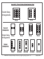
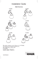
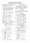
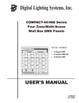
Appendix D - Protocol Stations Button Numbers Chart
1
2
3
4
Double-Gang
Arrangements
5 9
6 10
7 11
8 12
5
6
7
8
1
2
3
4
13
14
15
16
PS-12
PS-16
Standard
Arrangments
Single-Gang
Arrangments
Custom
Arrangments
2
2
3
6
PS-02
1
2
3
4
8
PS-05
13
14
15
16
1
2
3
6
7
PS-04
5
6
7
PS-06
1
2
3
4
1
2
4
PS-04-SC
PS-03-SC
5
6
7
8
1
2
3
4
PS-08
2
3
2
PS-02-SC
PS-01-SC
PROTOCOL Hardware/Software Manual by Digital Lighting Systems, Inc.
Revision 6/01
,
,
,
,
,
,
Phase
A, B, or C
Date:
4
80
8/
21
PD
40
4
PD
80
PD
Page
Of
6
6
21
8/
40
PD
S2 S1
Breaker #
Fe
e
N dP
um a
be nel
r
irc
R uit
ef
N ere
um n
c
be e
r
PD
A D im
dd m
re e
B
ss r
ox
#
O
ut
p
D ut #
im
m
Y abl
or e
N Loa
d
C
irc
W uit
at Lo
ts a
d
C
Ite
m
#
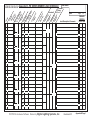
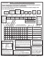
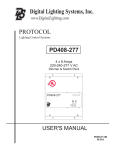
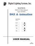
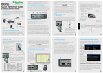
PROTOCOL Appendix B - PD SERIES DIMMER LOAD SCHEDULEBreakerJob Name:
Load Description/ Comments
PRIMARY
CONTROL
STA# SW#
1
2
3
4
1
2
3
4
1
2
3
4
1
2
3
4
1
2
3
4
1
2
3
4
PROTOCOL Hardware/Software Manual by Digital Lighting Systems, Inc.
Revision 6/01
Appendix B Page 1
PROTOCOL
{
PD408 & PD216
PD804
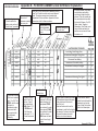
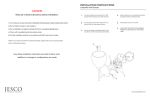
In order to keep a count
of circuits within the
system, enter an item #
in order from 1 upwards.
{
Appendix B - PD SERIES DIMMER LOAD SCHEDULE Explanation
Here enter any
other circuit
reference number
there may be.
Indicate here if the
load is dimmable
or not, Y for yes, N
for no.
Y
200
A1
Y
500
A1
Y
650
A1
A120
Y
950
A1
A205
Y
1500
B1
1
A101
2
3
A110
A112
4
5
0 1
0 2
6
Every set of four circuits has an address, starting
from 1 to 63 which must be set on each dimmer
pack. The system recognizes a hexadecimal
expression of these numbers. Appendix A has a
conversion chart for these numbers.
A250
1
2
X
X
Y
1800
B1
Enter total wattage for
the circuit here.
2
5
1
1
Incandescant downlights Dining Room
1
2
Fluorescant Cove Hallway
2
1
Incandescant Chandelier hallway
2
2
Incandescant Landscape Floodlights
1
5
Incandescant Swimming Pool Lights
1
6
Low Voltage Track Dining Room
1
2
In these columns, the primary
control station and switch
control each load should be
entered. This will normally be
the main station that controls
this load by Dimmer, On, Off,
Raise, Lower, Toggle or
Momentary. Every load must
have at least one switch to
perform one or more of these
functions on it.
A
B
Enter Feed Panel
Number here.
The decimal number
of the box is entered
here ( 1 to 63). The
PD804, whilst in one
enclosure is
considered as two
boxes, each with
four ouputs which
are addressed
differently.
The PD216 utilizes
outputs 1 and 4 in
each box, 2 and 3
shall remain blank.
PD408 utlizes 1, 2, 3
& 4. PD804 uses 1,
2, 3 & 4 from the
first box and 1, 2, 3
& 4 from the second
box.
Each PD Unit requires
maximum 2 x 20 amp
breaker feeds on the
same phase. PD216
uses one feed for each
of two outputs. PD408
uses one feed for each
two of four outputs.
PD804 uses one feed
for each four of eight
outputs.
Each PD series Dimmer pack takes
2 x 20 amp feeds to provide power
for the outputs and the internal
logic of the unit.
These two feeds must be on the
same phase in order for the logic to
work correctly. Failure in doing this
will cause the system to cease
operation in a normal manner.
In this column, details
about the load should be
enetered, sych as the
type of load, its location
and a brief description.
Appendix B Page 2
PROTOCOL
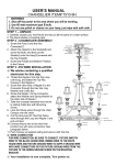
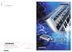
Appendix C - PS SERIES Switch Assignment Schedule Job Name:
Station # S2 , S1 setting Field Label
Part no. Plate Color Button Color Frame Color
XG
R
Sw
itc
h
#
(1
-1
6
)
Sw
itc
Fu h
nc Ty
tio pe
n
e:
Station Physical Location
,
,
,
,
,
,
,
,
,
,
,
,
,
,
,
,
,
,
,
,
Loads (circuits) controlled by Switch
Up to 24 circuits may be listed here per switch .
,
,
,
,
,
,
,
,
,
,
,
,
,
,
,
,
,
,
,
,
,
,
,
,
,
,
,
,
,
,
,
,
,
,
,
,
,
,
,
,
,
,
,
,
,
,
,
,
,
,
,
,
,
,
,
,
,
,
,
,
,
,
,
,
,
,
,
,
,
,
,
,
,
,
,
,
,
,
,
,
,
,
,
,
,
,
,
,
,
,
,
,
,
,
,
,
,
,
,
,
,
,
,
,
,
,
,
,
,
,
,
,
,
,
,
,
,
,
,
,
Page
Of
Please refer to Page 2 for
instructions on how to fill out
this form correctly.
Sw
it
La ch
be
l
at
e
Le
ve
to l 0
Sw -10
G
lo itc 0 (A
ba
h
l:G Ty ppl
/E pe ies
xc “O
lu
N
si
”)
v
Date:
Comments
,
,
,
,
,
,
,
,
,
,
,
,
,
,
,
,
,
,
,
,
PROTOCOL Hardware/Software Manual by Digital Lighting Systems, Inc.
Revision 6/01
Appendix C Page 1
PROTOCOL
Appendix C - PS SERIES Switch Assignment Schedule Explanation
This page is designed to show an example of how to fill in a switch assignment sheet. More information is provided in the
PROTOCOL SOFTWARE MANUAL and the PROTOCOL HARDWARE MANUAL.
First, the general station information must be filled in, and then the information for each switch, including the switch
function and the loads that it will affect.
Hexidecimal number
of station, Refer to
Appendix A.
Numeric number
of station.
h
R
Field Label
DLS part
number
for station
Part No.
PSC08
Color of
Face Plate
Plate Color
Black
Color of
Frame if
one is used.
Color of
Buttons
Button Color Frame Color
White
None
Station Physical Location
Living Room West Wall
Loads (circuits) controlled by Switch
Up to 24 circuits may be listed here per switch.
at
Sw
itc
h
Sw
itc
S2,S1 Setting
1,7
e
Le
ve
to l 0
Sw -10
itc 0 (
G
h Ap
lo
ba Typ pli
e es
l:G
“O
/E
N
xc
”)
lu
si
ve
:X
G
Ty
pe
(1
-1
6
)
Station #
23
#
Enter switch
number here,
refer to Appendix
D for correct
numbering of
switches.
A space for any
other name you
may want to label
station.
Station
Location
Information.
Description of
switch function
or any other
information
about that switch
such as a
different color
from others etc.
Comments
Switch Label
1
DI M-S
9
1,1
1,2
Dim Sconces
Sconce Dimmer Control
2
DI M
9
1.3
1.4
Dim Chand.
Chandelier Dimmer Control
3
PST 1 12 sec
1,1
1,2
1,3
1,4
Lunch
4
PST 2 15 sec
1,1
1,2
1,3
1,4
Dinner
5
ON
6
OFF
80
G
XG
Enter the switch type here. There are
several functions that may be selected.
Dimmer =
DIM Toggle =
TOG
On =
ON Off =
OFF
Raise =
RSE Lower =
LWR
Preset =
PST(#) Momentary = MOM
Unassigned = NONE
Note: i.) Every Preset has a number from1254 that must be assigned to it. ii.) When
Soft Switch is selected indicate with a “-S”
after the Type. Please see Protocol
Software Manual for more information.
1,1
1,2
Lunch Scene for living room Black butt.
Dinner Scene for living room
All On
Global on for whole house
All Off
Global off for whole house except
living room sconces
Selecting G (Global) will cause switch to affect every load on
the system. Indicating XG (Exclusive Global) will show that all
loads on system are affected except for those that have been
excluded (up to 24 circuits may be excluded from a Global
switch). Excluded circuits must be indicated in Loads Affected
by Switch columns.
When ON function is selected, the level may be determined.
0 is off, 100 is full on. Any value in between may be selected.
Enter the rate of cross-fade between scenes if switch is a PST. Rate
is 2-59 Seconds (sec) or 1-59 minutes (min).
Enter rate of dimming if a switch is DIM, ON, OFF, MOM, RSE or
LWR. Rate is 1-10. 1 is slowest, 10 is fastest. 9 is the default setting.
PROTOCOL Hardware/Software Manual by Digital Lighting Systems, Inc.
Enter information for label to appear
next to faceplate. No more than two
lines of six characters per switch.
Contact factory for more details.
Every switch must affect at least one load
on the system. The loads affected are
entered in these columns. Each switch may
affect up to 24 different loads or all loads
with up to 24 being excluded. A load must
be identified by the Box # then Output #
as entered on the PD Series DIMMER
LOAD SCHEDULE (APPENDIX B).
Revision 6/01
Appendix C Page 2
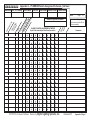
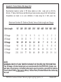
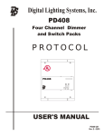
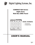
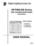
Appendix E - Protocol Stations Wire Gauge Chart
Recommended maximum number of PS Series stations (or other nodes such as DCI-16’s,
DCO-4’s, PT Series Patch Panels and RAU-96’s) per home run when using a 9 VOLT AC transformer.
Computations are based on an even distribution of nodes along the 9 VAC power line.
Maximum Number Of Stations (Nodes) Versus Cable Length and Gauge
Cable Length
22
20
18
16
14
12
Gauge
Gauge
Gauge
Gauge
Gauge
Gauge
50'
23
36
58
92
145
231
100' 150' 200'
11
18
29
46
73
116
8
12
19
31
48
77
6
9
14
23
36
58
250'
5
7
12
18
29
46
300' 400'
4
6
10
15
24
39
3
5
7
11
18
29
500' 600' 800'
2
4
6
9
15
23
2
3
5
8
12
19
1
2
4
6
9
14
NOTE:
MAXIMUM LENGTH OF DATA TWISTED PAIR MUST NOT EXCEED 1500' PER HOME RUN.
Two 18 Gauge or thicker twisted pairs are recommended for the PROTOCOL System, one
pair data, one pair power. A shielded cable may be used to provide a ground for all stations.
Carol Cable #C3362 or Equivalent 4-Wire (2 Twisted Pairs) Shielded Network Bus Cable may
be used
PROTOCOL Hardware/Software Manual by Digital Lighting Systems, Inc.
Revision 6/01
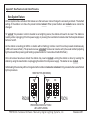
Appendix F: New Preset Lock and Unlock Procedure
New System Feature:
All new systems have a feature that makes sure that end-user cannot change the scenes by accident. The default
setting of the station is to have the preset buttons locked. When preset buttons are locked scenes cannot be
changed.
To “unlock” the presets in order to be able to set a lighting scene, the station will need to be reset. The station is
reset by either unplugging it from its power supply or pressing the reset button located under the faceplate between
buttons 1 and 5.
As the station is reseting (all LED’s on station will be flashing), buttons 4 and 8 must be pressed simultaneously
(LED’s will cease to flash). The presets are now unlocked. Scenes can now be set by the usual method (adjusting
light levels and then pressing and holding a preset button for 4 seconds until all LED’s flash)
.
Once all scenes have been stored, the station may now be locked. Locking the station is done by reseting the
station by using the reset button or unplugging the station from its power supply . The station is now locked
.
Individual light levels may still be changed whether station is locked or unlocked. Only presets buttons are affected
by this procedure.
RESET BUTTON (RECESSED)
1
5
1
5
9
13
2
6
2
6
10
14
3
7
3
7
11
15
4
8
4
8
12
16
PSC08
PSC16
PRESS SIMULTANEOUSLY WHILE
LED’s ARE FLASHING
PROTOCOL Hardware/Software Manual by Digital Lighting Systems, Inc.
Revision 6/01