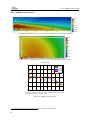
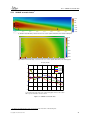
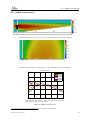
1
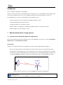
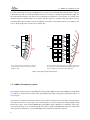
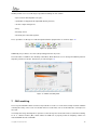
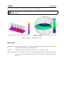
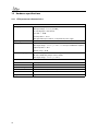
StepArray
manual
L ' a c o u s t i q u e
a c t i v e
CONTENTS
Contents
Contents
2
I
4
StepArray: tutorial for recommandation
1 Sound reinforcement in large spaces
5
2 Overview of the StepArray system
9
3 Choosing the right installation set-up
12
4 Column positionning rules
14
5 Options
16
6 SAdrive software
16
7 CAD modeling
17
References
18
II
20
StepArray technical reference
8 Installation of the columns
21
9 Wiring
22
10 Test before powering up
25
11 SAdrive software
26
12 Advanced functions
27
13 Troubleshooting
30
14 Hardware specifications
32
15 Acoustical data
37
List of Tables
44
List of Figures
44
2
CONTENTS
Foreword
StepArray is a versatile line-array system designed for speech reinforcement in large spaces. It offers excellent
sound intelligibility, slim design, external electronics, security systems compatibility and more.
This reference manual is intended to be a user manual for StepArray based systems, as well as a complete reference
with all the technical specifications and details about the StepArray system.
How to use this manual
This reference manual is divided in two parts:
• The first part is a tutorial for recommandation. It deals with StepArray design and principles, introducing
the acoustic background necessary to understand sound reinforcement in large space, and how StepArray
can help to achieve good intelligibility in these places.
• The second part is a technical reference describing the full range of StepArray products. It covers installation, wiring, maintenance, and tuning. Extensive technical data is found there.
Last update: December 23, 2010
3
Part I
StepArray: tutorial for recommandation
Table of Contents
1
2
3
Sound reinforcement in large spaces
5
1.1
General issues with public address in large spaces . . . . . . . . . . . . . . . . . . . . .
5
1.2
Loudspeaker arrays
. . . . . . . . . . . . . . . . . . . . . . . . . . . . . . . . . . . . .
7
1.3
DGRC: The StepArray system . . . . . . . . . . . . . . . . . . . . . . . . . . . . . . .
8
Overview of the StepArray system
2.1
StepArray system example . . . . . . . . . . . . . . . . . . . . . . . . . . . . . . . . . .
10
2.2
StepArray column models . . . . . . . . . . . . . . . . . . . . . . . . . . . . . . . . . .
11
2.3
StepArray specificity: shared electronics . . . . . . . . . . . . . . . . . . . . . . . . . .
11
Choosing the right installation set-up
12
3.1
Columns . . . . . . . . . . . . . . . . . . . . . . . . . . . . . . . . . . . . . . . . . . . .
12
3.2
Processors . . . . . . . . . . . . . . . . . . . . . . . . . . . . . . . . . . . . . . . . . . .
13
3.3
Amplifiers . . . . . . . . . . . . . . . . . . . . . . . . . . . . . . . . . . . . . . . . . . .
13
3.4
Cables
. . . . . . . . . . . . . . . . . . . . . . . . . . . . . . . . . . . . . . . . . . . .
14
3.5
Subwoofers . . . . . . . . . . . . . . . . . . . . . . . . . . . . . . . . . . . . . . . . . .
14
4
Column positionning rules
14
5
Options
16
5.1
Microphone (MIC) . . . . . . . . . . . . . . . . . . . . . . . . . . . . . . . . . . . . . .
16
5.2
Sub-bass Output (SUB) . . . . . . . . . . . . . . . . . . . . . . . . . . . . . . . . . . .
16
5.3
Sound Security System (SSS) . . . . . . . . . . . . . . . . . . . . . . . . . . . . . . . .
16
6
SAdrive software
16
7
CAD modeling
17
References
4
9
18
Introduction
This is a tutorial for StepArray recommandation.
Section 1 presents general issues about public address in large spaces (1.1) and explains how loudspeaker arrays
can be a good solution to these issues (1.2). StepArray is introduced as the last point of this section (1.3).
The following parts are a step by step introduction to the StepArray system:
• Section 3 explains the rules to follow when designing a StepArray system,
• Column positionning is described in section 4,
• The different options are described in section 5,
• SAdrive software, serving both as a simulation and tuning software, is described in section 6,
• CAD modeling tools are presented in section 7.
1
1.1
Sound reinforcement in large spaces
General issues with public address in large spaces
Speech reinforcement in large and reverberant rooms is made difficult by several causes, namely reverberation,
ambient noise, and architectural constraints.
Reverberation
In all rooms, sound transmission from a loudspeaker to a listener can be divided in two parts (figure 1):
• Direct sound, which depends on the loudspeaker-to-listener distance and on the loudspeaker directivity.
• Reverberated sound, which depends on the geometry of the room, and the acoustical properties of the walls.
In large spaces (church, railway station), the reverberation can be very important and plays a negative role
on speech intelligibility (Note that the energy of the reverberated sound is constant throughout the room).
Reverberated
sound
Direct so
und
Figure 1: Direct sound increases speech intelligibility, reverberated sound impairs it.
Intelligibility rule #1:
Direct sound increases speech intelligibility, reverberated sound impairs it.
Last update: December 23, 2010
5
1.1
General issues with public address in large spaces
Ambient noise
Ambiant noise reduces intelligibility. For example, the loud noise produced by trains in railway stations could prevent
the listener from understanding a message properly. Also, the noise level can change drastically over time: in this
case, the public address system must adjust its diffusion level according to the noise level.
Intelligibility rule #2:
The public address sound system should emit at least 10dB above the ambient noise level.
Architectural constraints
Loudspeakers positionning is often restricted by architectural or practical constraints. Because loudspeakers are
not always welcome in places where aesthetics are important, they should be made discreet and as few as possible
should be used.
Speech intelligibility in large spaces
As seen above, speech intelligibility1 depends on:
• Reverberation time. This is a caracteristic of the room acoustics and depends on the material of the wall and
the geometry of the room.
•
Direct Sound
Reverberated Sound
energy ratio. This depends on reverberation time, room volume2 , loudspeaker to listener
distance, and loudspeaker directivity.
•
Signal
Noise
ratio. This depends on the ability of the sound system to emit enough energy to «cover the noise».
In large spaces, changing the reverberation time involves changing a significant portion of the wall material, and
most of the time, this is not possible.
Providing a strong signal to noise ratio is also important, but it is not enough to ensure intelligibility.
Therefore, in large and reverberant rooms, the most important parameter the public address must affect is the
Direct Sound
Reverberated Sound
ratio. It is necessary to privilege the direct sound energy and avoid putting energy in the reverberated
part of sound. This can be achieved either by moving the loudspeaker close to the listener, or by using highly
directional loudspeakers.
In a large and highly reverberant room, it is necessary to privilege the direct sound energy for good
intelligibility results.
In large spaces, if the loudspeakers are to be placed close to the listeners, many loudspeakers are required. This
is not practical in such places because fixing loudspeakers can be difficult (very high ceiling, etc). Also, in many
cases, this will not give good intelligibility results because only the loudspeakers close to the listener contribute to
the direct sound, while all the loudspeakers contribute equally to the reverberated sound.
1
Several indexes have been proposed to measure speech intelligibility. The most widely used of them is the Speech Transmission Index (STI).
Value 0 corresponds to extremely poor intelligibility, and value 1 corresponds to perfect intelligibility. It is generally considered that intelligibility is
correct above STI=0.55.
time
2
Energy of the reverberated field is proportionnal to the ratio Reverberation
.
Room volume
6
1.2
Loudspeaker arrays
Using many non-directional loudspeakers often leads to poor intelligibility: all loudspeakers contribute to the
reverberation, while only a few contribute to direct sound.
Using highly directionnal loudspeakers is an easier solution in large spaces because only few diffusers are needed.
In addition to improved acoustic performance and reduced cost, it minimizes the aesthetical impact of the public
address system.
Sound quality
Intelligibility is not enough for good perceived sound quality. Another very important aspect is that every listener has
an adequate sound pressure level (SPL), which implies that the public address system provides an even coverage
of the audience area. This can be acheived with an accurate control of the loudspeaker directivity.
Acoustic comfort also implies a wide frequency bandwidth and low harmonic distortion.
The most important goal of a public address system is to provide a strong and constant direct sound over the
entire audience area, and minimize the energy emitted elsewhere.
1.2
Loudspeaker arrays
Loudspeaker arrays are often the best solution to providing strong and constant direct sound over the audience.
Indeed, although a distributed public address system might yield a relatively constant SPL over the audience using
a large number of loudspeakers, it is usually not able to provide satisfactory speech intelligibility when reverberation
in the room is high. In addition, it usually has a rather negative impact on the visual aspect of the room.
In contrast, high speech intelligibility can be obtained with a limited number of loudspeaker arrays (often only 1 or
2) in a large and highly reverberant room with minimum impact on the aesthetics of the room.
It is easy to calculate the shape of the wave front that should be radiated by a loudspeaker array in order to yield
constant SPL over the entire audience area, and minimize sound energy emitted elsewhere. A J-shape wave
front is obtained, in which the local curvature depends on the focal distance, as illustrated on figure 2. In order
to generate such a wave front, one can align loudspeakers along the J-shape as in geometric arrays (figure 3a
on the following page) [C-HEIL], or place loudspeakers on a vertical line and rely on the filtering of each individual
loudspeaker as in electronic arrays (figure 3b on the next page) [DSP directivity]. The latter case corresponds to
column loudspeakers, which can be flush mounted on a wall. Advantages and disadvantages of both array types
are discussed in [DGRC-Arrays].
Wave
front
r2
d2
r1
d1
x1
Listening plan
x2
Figure 2: J-shape wave front required in order to radiate constant SPL over the listening plan.
Last update: December 23, 2010
7
1.3
DGRC: The StepArray system
The main characteristic of an array is its range, which corresponds to the minimum and maximum distance (from the
column) where the SPL is constant (with a given tolerance). The range of a column is proportional to its height. Another important characteristic of an array is the spacing between loudspeakers. Good rejection of secondary lobes
at high frequencies is obtained with a short spacing. At high frequencies, geometric arrays generally use waveguides that radiates like an isophase vertical slit. Aligning several of these waveguides yields a semi-continuous “line
source”, which greatly reduces undesired secondary lobes.
Signal
Signal
Wave
front
(a) In a geometric array, loudspeakers are aligned
along the shape of the wave front to be generated,
usually a J shape.
D1
F1
G1
D2
F2
G2
D3
F3
G3
D4
F4
G4
D5
F5
G5
D6
F6
G6
Wave
front
(b) In an electronic array, loudspeakers are aligned vertically, and
the wave front is synthesized by adequate filtering by filters Fi , delays Di , and gain Gi associated to each loudspeaker.
Figure 3: Electronic and geometric arrays
1.3
DGRC: The StepArray system
The StepArray columns implement the DGRC line-array principle (Digital and Geometric Radiation Control) which
is a synthesis of geometric and electronic arrays patented by Active Audio. The principle is illustrated in figure 4 on
the facing page.
The key idea is to split the desired wave-front into sections and move them back on a vertical line, much like what is
done in the Fresnel lenses used in optics. Then electronic delays are used to compensate sound propagation delay
between the sections. It was shown in [DGRC-Arrays] that with this delay setting there is no diffraction at the edges
of the saw-tooth shape. As a result of this principle, the number of DSP and amplification channels is independent
of the number of loudspeakers, so that a dramatically reduced number of channels is achieved.
8
F1
D1
G1
A1
F2
D2
G2
A2
Wave
front
F3
D3
G3
A3
Input
EQ
signal
di
F4
D4
G4
A4
F5
D5
G5
A5
F6
D6
G6
A6
Figure 4: The DGRC principle used by StepArray columns. The wave front is controlled both by the positioning and
orientation of the loudspeakers, and by filters Fi , delays Di , and gain Gi of each channel.
The main advantages brought by the DGRC principle used in StepArray columns are:
• The column is vertical and can be fitted close to the wall.
• Reduced number of electronic channels, both for DSP and amplifiers. For example, model SA250P which is
2.5m high uses only 6 channels for 30 loudspeakers. This can make a big cost difference.
• Power is uniformly distributed to all loudspeakers. This way they can all be used at their maximum capabilities,
enhancing overall performance and sound pressure level.
• The number of channels does not depend on the number of loudspeakers. Therefore, many small full-range
loudspeakers can be used to obtain perfect sound quality in the treble range and reduce secondary lobes at
higher frequencies.
2
Overview of the StepArray system
The StepArray range consists of several column models dedicated to speech diffusion and to mid-power music
diffusion in large and/or reverberant enclosed spaces. The different models allow coverage of flat or tilted audience
area ranging from 15m to 68m with perfect speech intelligibility and high sound quality.
Last update: December 23, 2010
9
2.1
StepArray system example
StepArray columns use external electronics. They are controlled by the UT26 digital signal processor (DSP) and
powered by the MPA6150 6-channel amplifier. Having external electronics has the following advantages:
• Possibility to use a single UT26 processor controling several columns, yielding a large cost reduction
(see section 2.3 on the next page).
• Possibility to use several amplifiers for a single column in order to increase security: failure of one amplifier
would only affect some of the channels, but the column continues to diffuse messages. For example, when
using 2 columns and 2 amplifiers, amplifier 1 can be connected to channels 1, 3, 5 of both columns, and
amplifier 2 to channels 2, 4, 6 of both columns.
• Easier maintenance: all electronics can be easily accessed in the technical room.
• Electronics can be placed in a fireproof room, with uninterruptible power supply (UPS).
The operating parameters of the UT26 processors are tuned with the SAdrive software through RS232 serial
communication. UT26 processors feature filtering functions such as the control of directivity, equalization, delay,
and high level functions.
In addition, the StepArray system features a set of options such as subwoofer output (SUB), active gain control
(AGC), and security system supervision (SSS).
2.1
StepArray system example
Figure 5 is an example of a complete StepArray installation.
The audio signal is fed into the UT26 processors which then supply DGRC compatible signals to the MPA6150
amplifiers. A UT26 can also provide sub-bass output when equipped with the SUB option. The settings are made
with the SAdrive software through an RS232 serial bus.
SA250P
4x SA100P
SA250P
SA12-SWA
3x MPA6150
2x UT26
BAN
RS232
Audio input
Figure 5: Example of StepArray system
10
2.2
2.2
StepArray column models
StepArray column models
Table 1 on the next page and table 2 on page 13 give an overview of the StepArray models characteristics. A
complete description of the technical characteristics can be found in sections 14 and 15.
SA400P
SA250P
SA180P
SA100P
3m
2.5m
30m
15m
35m
68m
Floor
Figure 6: Listening zones (P-models)
SA250S
SA180S
or
Flo
3.8m
2.6m
10°
4m
22m
28m
Figure 7: Listening zones (S-models)
Columns whose name ends with a «P» (SA100P for example) are designed for horizontal audience areas,
whereas column whose name ends with a «S» are designed for tilted audience areas (or with balcony).
2.3
StepArray specificity: shared electronics
One of the advantages of using external electronics is that several columns can be connected (via their amplifier) to
the same UT26 processor.
A UT26 processor features 6 analog symmetrical outputs. Therefore a single UT26 processor can be used to deliver
signals for:
• a 6 channel column,
• one or two 3 channel columns.
Moreover, a UT26 processor can be connected to one or several StepArray amplifiers (to feed several columns with
the same signal). In this case, the inputs are simply daisy chained to the amplifiers (see section 9.1 on page 22).
Last update: December 23, 2010
11
In the example installation figure 8, three independant rooms are equipped with StepArray columns. Each room
receives its own signal and can have independant parameters. For a total of 6 columns, only 2 processors and 3
amplifiers are needed!
Lounge: 2 x SA100P
Conference room: 2 x SA180S
Hall: 2 x SA250P + SUB
3x MPA6150
2x UT26
Lounge input
Conference input
Hall input
Figure 8: Shared electronics example
3
Choosing the right installation set-up
3.1
Columns
All StepArray columns feature a large frequency bandwidth and a wide horizontal opening angle3 . The columns
are mounted vertically using the supplied square brackets. The columns are available in standard RAL colors
RAL9016 and RAL9005, but any other RAL color is available with the COL option. Table 1 sums up these characteristics.
Max SPL
Hor. opening
Bandwidth
Mounting
Colors
95dBSP L
180°
(-6dB)
135Hz-17kHz (-3dB)
110Hz-19kHz (-10dB)
Vertical
(supplied
square brackets)
White RAL9016
Black RAL9005
Any RAL (COL option)
(pink noise,
in listening area)
Table 1: General characteristics of StepArray columns.
StepArray columns do not use opening angle and tilting angle to tune directivity. Instead, StepArray use the listening area definition to automatically adjust themselves as to fit the requirements to the best.
StepArray columns use the listening area definition to automatically adjust themselves.
3
12
The horizontal opening angle corresponds to a 6dB attenuation for the average of the 1 kHz and 2 kHz octaves.
3.2
Processors
The StepArray range provides a full set of listening ranges4 and audience tilting angles to suit any public address
situation. The listening areas, as described on figure 9, are listed on table 2. The nominal situation corresponds
to the conditions for which the column has been designed. By specifying the effective positioning of the column
and the shape of the listening area in the Directivity bloc of SAdrive, the DSP filtering parameters are automatically
adjusted to the situation.
Choose the column which covers the most of the listening area.
Liste
h
ning
a r ea
Floo
r
θ
0
Range
dmin
Figure 9: Listening area definition
Model
Height
Nominal altitude h
(standing/seated audience)
Audience
angle (θ )
Range 500Hz-2kHz
(±3dB / ±5dB)
Min. distance
(dmin )
Channel
count
SA100P
SA180P
SA250P
SA400P
1m
1.8m
2.5m
4m
2.5m / 2.1m
2.5m / 2.1m
2.5m / 2.1m
3.0m / 2.6m
Flat (0-5°)
Flat (0-5°)
Flat (0-5°)
Flat (0-3°)
15m / 21m
30m / 40m
35m / 45m
68m / 90m
1m
1m
1m
1m
3
3
6
6
SA180S
SA250S
1.8m
2.5m
3.0m / 2.6m
4.2m / 3.8m
Tilted (5-20°)
Tilted (5-20°)
22m / 29m
28m / 36m
4m
4m
3
6
Table 2: Specific characteristics of StepArray column models.
3.2
Processors
The UT26 processor has 6 output channels, therefore it can deliver signals for two 3 channel columns, or one 6
channel column.
It is also possible to connect two 3 channel columns with different signals on the same processor to obtain a stereo
sound. Independent settings are available for directivity, equalization, and delays. All these settings can be saved
and recalled remotely thanks to presets.
More details on wiring can be found in section 9.1.
3.3
Amplifiers
The MPA6150 amplifier is capable of delivering 6 × 150 watts under 4Ω load, or 6 × 100 watts under 8Ω loads.
More details on wiring can be found in section 9.1.
4
The range of a column is defined as the maximum distance from the column for which the mean sound level for the octaves 500Hz, 1 kHz,
and 2 kHz remains within ±3dB or ±5dB .
Last update: December 23, 2010
13
3.4
3.4
Cables
Cables
Cable lengths detailed in table 3 correspond to the maximum lengths recommended for the amplifier to column
cable5 .
Cable length
Wire diameter
< 300m
< 500m
1.5mm2
2.5mm2
Table 3: Wiring recommendations for StepArray columns.
For very long distances exceeding the maximum cable length mentioned in table 3, please contact Active Audio.
• 3 channel columns need a 4 wire cable.
• 6 channel columns need a 7 wire cable.
3.5
Subwoofers
In cases where the StepArray system diffuses music, the sound fidelity will be better if a subwoofer and its associated
amplifier are added. This option is not necessary for installations aimed at vocal diffusion since the human voice
hardly has component frequencies in the bass range below 150 Hz.
The subwoofer signal is delivered by an UT26 processor fitted with the SUB option (see section 5.2).
Active Audio proposes subwoofers (SA12-SW and SA12-SWA) suitable for StepArray installations (see section
14.3).
4
Column positionning rules
When choosing a StepArray setup, the goals are:
• Ensuring proper SPL coverage,
• Delivering satisfying intelligibility of vocal messages,
• Avoiding echoes and feedback effects,
• Giving the feeling that the sound comes from the speaker.
The positioning of columns should follow a few basic rules:
• Use as few columns as possible: choose the column covering as much of the listening area at once.
• Add more columns only if necessary. Beware: intelligibility could be impaired if there are too many columns.
• Columns should be placed so as to obtain the most homogeneous sound level over the audience area.
• For complex cases, it is highly recommended to use CAD software which will take into account the acoustics
of the room. CAD tools are presented in section 7.
5
14
These maximum cable lengths correspond to a sound level loss of 3dB.
• Place the columns as close as possible to the nominal altitude (see table 2 on page 13). When placing
columns at non nominal altitude, use SAdrive software to check that column emission will be acceptable.
When dealing with several columns, the differences of propagation distances6 for columns covering the same
listening area should be less than 20m. so as to avoid possible echoes for certain sections of the audience. See
figure 10.
Column 1
Column 2
If |d1-d2| < 20m, there is no echo
d1
d2
Listening area
Listener
Figure 10: Interferences between columns
Also, consider microphones and stage:
• the speaker must be placed at less than 15 m from the columns, otherwise he will hear the echo of his own
voice.
• the audience must feel that the sound comes from the speaker. This is achieved by fitting a column on each
side of the stage so as to «re-centre» the sound. A single column can be used but in this case it has to be
close to the zone to be covered.
• Prevent the feedback effect: there should never be a microphone aiming at a column; this could generate a
feedback problem.
The impact of the room acoustics on the sound level within the covered zone is relatively low a , since the fundamental aim of the StepArray columns is to provide a strong direct sound in order to ensure high intelligibility,
even in reverberant spaces.
a
6
SPL reinforcement by reverberation can be higher close to walls.
In this context, propagation distance is the column to listener distance.
Last update: December 23, 2010
15
5
Options
Several options are available for the StepArray system. These options bring additional electronic cards within the
UT26 processor and the columns. A marqued plaque on the back of the processor indicates the options as shown
in figure 11.
Serial number
137
CV232
SUB
Audio Bus - BAN848
MIC
SSS
Active Audio
UT26 Processing Unit - Made in France
Local Bus - BCL
Computer - RS232
Figure 11: Indication of options on the rear panel of the UT26 processor (CV232 only in this example).
5.1
Microphone (MIC)
This option brings an electret microphone in the connection box at the back of the column, and its phantom power
supply delivered through input 2 by the UT26 processor.
This option is needed to enable the AGC (automatic gain control) function (section 12.1).
5.2
Sub-bass Output (SUB)
When playing music, it is generally necessary to complement the columns with a sub-bass loudspeaker. The SUB
option gives a sub-bass output on the BCL port of the UT26 processors (wiring is described in section 9.6).
When using the SUB option, the subwoofer signal is low-pass filtered by the UT26 processor with a 4th order
Linkwitz-Riley type at 180 Hz, and the column’s signal is filtered with the complementary high-pass filter.
Note that for speech diffusion, there is no point extending the bass response.
5.3
Sound Security System (SSS)
The SSS option (Sound Security System) brings EN-60849 conformance to a StepArray system. It is suitable for
installations diffusing security messages. It consists of monitoring of proper functioning of the system as per the
requirements of the norm, using two daughter boards inside the UT26 processor and a sensor for electric current
measurement. Processor, amplifier, and speaker faults are detected.
Beyond the norm:
The SSS option is a great way to ease maintenance of an installation by keeping you informed of proper
fonctionning.
6
SAdrive software
The SAdrive software is primarly used to tune the operating parameters of StepArray columns, but it is also a great
simulation tool. The software can be downloaded for free on Active Audio’s website:
http://www.activeaudio.fr/en/gamme-steparray/sadrive
16
SAdrive provides access to a full range of operations including, for each column:
• input selection with adujstable noise gate,
• equalization: 6 fully parametric biquadratic filtering elements,
• sub-bass output management,
• delay,
• directivity control,
• automatic gain control management,
These operations are directly accessible through the SAdrive Synoptic frame as shown on figure 12.
Figure 12: Synoptic frame
Additionally, it is possible to save and recall operating parameters in presets.
The main feature of SAdrive is the directivity control block, which allows the user to change the radiation pattern of
StepArray columns in real-time. This block is presented in figure 13.
Figure 13: SAdrive directivity block
7
CAD modeling
There are powerful CAD software tools that can predict the acoustics of a room and accurately model the radiation
of loudspeaker arrays. These tools can calculate various acoustic index, such as reverberation time, sound pressure
level, STI. . .
In a loudspeaker array, all loudspeakers operate in a coherent way. This must be taken into account in the modeling.
To do so, software modules (DLL) which enables the CAD tools to properly model the StepArray columns are
included inCATT-Acoustic and EASE.
Last update: December 23, 2010
17
REFERENCES
Figure 14 shows examples of a modeling results for CATT-Acoustic and EASE.
With the StepArray DLLs, the directivity parameters can be adjusted as can be done in real situation with the
SAdrive software.
(a) Example of RASTI modeling using software CATT-Acoustic®.
(b) Balloon plot of SPL radiated in octave 1 kHz by column SA250S.
Simulation with EASE®.
Figure 14: Examples of a CAD modeling results.
References
[DGRC-Arrays] X. Meynial, «DGRC arrays : A synthesis of geometric and electronic loudspeaker arrays», AES
120th Convention. Preprint 6786, Paris May 2006.
[C-HEIL]
«Sound Wave Guide», US Patent # 5,163,167, Inventor : C. Heil, nov 10 1992.
[DSP directivity] G.W.J. van Beuningen; E.W. Start; «Optimizing Directivity Properties of DSP Controlled Loudspeaker Arrays», Reproduced Sound 16 Conference, Stratford (UK) 17-19 Nov 2000, Institute of
Acoustics.
18
StepArray
Technical manual
L ' a c o u s t i q u e
a c t i v e
Part II
StepArray technical reference
Table of Contents
8
Installation of the columns
21
9
Wiring
22
9.1
UT26 processor to amplifier . . . . . . . . . . . . . . . . . . . . . . . . . . . . . . . . .
22
9.2
Amplifier setup . . . . . . . . . . . . . . . . . . . . . . . . . . . . . . . . . . . . . . . .
22
9.3
Wiring amplifiers to columns . . . . . . . . . . . . . . . . . . . . . . . . . . . . . . . .
23
9.4
Wiring the microphone (MIC option) . . . . . . . . . . . . . . . . . . . . . . . . . . . .
23
9.5
RS232 wiring . . . . . . . . . . . . . . . . . . . . . . . . . . . . . . . . . . . . . . . . .
24
9.6
SUB wiring . . . . . . . . . . . . . . . . . . . . . . . . . . . . . . . . . . . . . . . . . .
25
10 Test before powering up
25
11 SAdrive software
26
11.1 Init new processors . . . . . . . . . . . . . . . . . . . . . . . . . . . . . . . . . . . . . .
26
11.2 Check connected processors . . . . . . . . . . . . . . . . . . . . . . . . . . . . . . . . .
27
12 Advanced functions
12.1 Automatic gain control: AGC . . . . . . . . . . . . . . . . . . . . . . . . . . . . . . . .
27
12.2 Security Sound System: SSS . . . . . . . . . . . . . . . . . . . . . . . . . . . . . . . . .
28
12.3 Feedback killer . . . . . . . . . . . . . . . . . . . . . . . . . . . . . . . . . . . . . . . .
29
12.4 Remote control . . . . . . . . . . . . . . . . . . . . . . . . . . . . . . . . . . . . . . . .
30
13 Troubleshooting
30
14 Hardware specifications
32
14.1 UT26 processor characteristics . . . . . . . . . . . . . . . . . . . . . . . . . . . . . . .
32
14.2 MPA6150 amplifier characteristics . . . . . . . . . . . . . . . . . . . . . . . . . . . . .
33
14.3 Subwoofers characteristics . . . . . . . . . . . . . . . . . . . . . . . . . . . . . . . . . .
34
14.4 Columns characteristics . . . . . . . . . . . . . . . . . . . . . . . . . . . . . . . . . . .
35
15 Acoustical data
20
27
37
15.1 Common data . . . . . . . . . . . . . . . . . . . . . . . . . . . . . . . . . . . . . . . . .
37
15.2 SA100P acoustical data . . . . . . . . . . . . . . . . . . . . . . . . . . . . . . . . . . .
38
15.3 SA180P acoustical data . . . . . . . . . . . . . . . . . . . . . . . . . . . . . . . . . . .
39
15.4 SA250P acoustical data . . . . . . . . . . . . . . . . . . . . . . . . . . . . . . . . . . .
40
15.5 SA400P acoustical data . . . . . . . . . . . . . . . . . . . . . . . . . . . . . . . . . . .
41
15.6 SA180S acoustical data . . . . . . . . . . . . . . . . . . . . . . . . . . . . . . . . . . .
42
15.7 SA250S acoustical data . . . . . . . . . . . . . . . . . . . . . . . . . . . . . . . . . . .
43
List of Tables
44
List of Figures
44
8
Installation of the columns
StepArray columns are mounted verticaly, usually on a wall, using the supplied brackets. Figure 15 illustrates the
steps to follow for column mounting. See also figure 25 on page 36 for technical drawings of the brackets.
1
2
x3
Place
the 2 brackets
on the wall
using 8mm
diameter screws
Column height
+ 5mm
x3
3
4
Ensure
verticality
Mount the column
using the supplied
nut and screw
Figure 15: Column mounting on a wall
It is important to ensure verticality when mounting StepArray columns.
Last update: December 23, 2010
21
9
9.1
Wiring
UT26 processor to amplifier
A UT26 processor can be connected to one or several StepArray columns via amplifiers (see figure 16). When a
UT26 is used with several amplifiers (to feed several columns with the same signal), the inputs are simply daisy
chained (see figure 16b).
UT26
6 XLR-F to WAGO
MPA6150
UT26
6 XLR-F to WAGO
MPA6150
MPA6150
(a) Direct wiring
(b) Daisy chain wiring
Figure 16: UT26 to MPA6150 wiring
XLR-F to Wago cables use standard XLR wiring convention as shown in table 4.
XLR
Wago
pin 1
pin 2
pin 3
Ground
pin +
pin -
Table 4: XLR to Wago wiring.
9.2
Amplifier setup
MPA6150 amplifiers should be tuned with all gains to max, and microswitches set for independent channels, as
described in figure 17.
All gains
to max.
6 XLR-F to WAGO
IN3
1 3
SOURCE
STEREO
IN4
BRIDGE
2 4
SOURCE
Set all microswitches for 6 independent channels
Figure 17: MPA6150 amplifier set-up
22
9.3
9.3
Wiring amplifiers to columns
Wiring amplifiers to columns
Wiring amplifiers to columns is straightforward: simply connect each channel of the MPA6150 amplifier to the
corresponding channel of the column and provide a common ground, as illustrated by figure 18.
1+
2+
3+
4+
5+
6+
1+
2+
3+
Not
Used
Not
Used
GND
SA180P
SA100P
SA250P
GND
6 channel column cabling
on MPA6150 amplifier
CH1
CH2
+ - - +
1+
GND
2+
CH3
CH1
Column output
on channels 4, 5, 6
Column output
on channels 1, 2, 3
CH4
CH3
+ - - +
CH4
CH5
+ - - +
3+
GND
CH6
+ - - +
1+
2+
CH2
CH3
CH4
+ - - +
+ - - +
1+ GND 2+
3+
4+
CH5
CH6
+ - - +
5+
6+
3+
6 channels
3 channels
Figure 18: MPA6150 to column wiring
9.4
Wiring the microphone (MIC option)
The MIC option consists of a microphone integrated inside the column and a daughter board placed inside the UT26
processor, which supplies phantom power on input 2 of the processor.
The microphone output of the column should be linked to input 2 of the UT26 processor using a shielded conductor
pair. Wiring is described in table 5.
GND
Pin 1
+
Pin 2
Pin 3
Table 5: Wiring of the microphone: standard XLR.
Last update: December 23, 2010
23
9.5
9.5
RS232 wiring
RS232 wiring
Only one processor should be connected with RS232 to the computer. If there are several UT26 processors, then
communication with all processors is possible when the BAN connectors are connected in daisy chain. This is
illustrated in figure 19.
Computer is
connected to
UT26 with CV232 option
CV232
SUB
CV232
SUB
MIC
SSS
MIC
SSS
DB9 female-female null-modem cable
BAN848 - Audio Bus
UT26 processors are connected by the BAN
Figure 19: RS232 wiring diagram
RS232 wiring uses standard DB9 null-modem wiring as shown in figure 20.
6
7
8
9
1
5
2
4
3
3
4
2
5
1
9
8
7
6
Figure 20: RS232 wiring: standard DB9 null-modem.
When several UT26 processors are used, they can be inter-connected by the BAN connector. In this case
only one of the UT26 connected to the BAN must be fitted with the CV232 option.
The CV232 option is disabled by putting the JP1 jumper of the CV232 board to «PC» position.
When the distance between the computer and the processor is over 30 meters, it is possible to use an RS485
port connected to the command channel (GND on pin 1, - on pin 2, + on pin 15) of the BAN connector. In
this case, the CV232 option is not needed.
24
9.6
9.6
SUB wiring
SUB wiring
When the UT26 processor is equipped with the SUB option (section 5.2), a sub-bass output is delivered on the BCL
port of the UT26 processor. Table 6 describes the wiring used.
Pin
Sig
pin 5
pin 6
pin 14
+
Ground
Table 6: SUB wiring on BCL port.
10
Test before powering up
Before powering up an installation, it is good practice to ensure that the column cable is properly connected to the
column. Therefore, the electrical resistance of each channel of the column must be controlled at the end of the
cable connected to the amplifier side. The measured electrical resistances values must correspond to the values
below.
Channel
1
2
3
4
5
6
SA100P
6.6Ω
6.6Ω
6.6Ω
SA180P
6.6Ω
6.6Ω
6.6Ω
SA250P
6.6Ω
6.6Ω
6.6Ω
4.4Ω
4.4Ω
4.4Ω
SA400P
6.6Ω
6.6Ω
6.6Ω
6.6Ω
6.6Ω
6.6Ω
SA180S
6.6Ω
6.6Ω
6.6Ω
SA250S
3.3Ω
6.6Ω
6.6Ω
4.4Ω
4.4Ω
3.3Ω
For details on connector pin assignement, see figure 18 on page 23.
When measuring the electrical resistance, the cable resistance must be taken into account (about 1.3Ω for
100 meters of 1.5mm2 ; 0.7Ω for 100 meters of 2.5mm2 ).
Last update: December 23, 2010
25
11
SAdrive software
The SAdrive software is used to tune all the filtering parameters of StepArray columns, it is available as free download here:
http://www.activeaudio.fr/en/gamme-steparray/sadrive
11.1
Init new processors
When a new processor (factory settings) is first connected to SAdrive, it needs to be initiated. The initalization steps
are described below.
1
2
Log in administrator mode.
Switch OFF all processors
OFF
UT26
UT26
OFF
3
4
Connect to COM port
Switch ON the processor
connected with CV232
ON
UT26
UT26
OFF
5
6
Set initial parameters
for this processor,
then apply.
Switch ON one more processor.
ON
UT26
UT26
ON
Remember: Switch ON one processor at a time.
7
8
Set initial parameters
for this processor,
then apply.
Processor address
must be unique.
Repeat step 6 and 7 for
each other processor.
26
Save as boot setup to make all changes permanent.
11.2
11.2
Check connected processors
Check connected processors
Already inited processors don’t show up automatically in SAdrive. To discover those processors, follow the steps
below:
1
2
Connect to COM port.
12
Discover from harware setup.
Advanced functions
12.1
Automatic gain control: AGC
Automatic Gain Control is available if the UT26 processor is equipped with the MIC option (section 5.1).
AGC allows automatic adjustment of the diffusion level according to the sound level captured by the microphone
when no message is played. Using this function, the sound level perceived by listeners is adjusted for optimal
comfort: moderate level when the ambiant noise is low, higher level when the ambiant noise is high in order to
provide good intelligibility.
The amplitude of the ambiant noise captured by the microphone is smoothed with a time constant adjustable by
the user. This resulting smoothed value is used as a basis for gain calculation: below a threshold adjustable by the
user, the AGC gain is set to 0dB ; above this threshold, the AGC gain increases proportionally to the ambiant noise
up to +12dB .
For example:
• If the ambiant noise is 75dBSP L and the AGC enters in action (Threshold) at 65dBSP L , then the AGC gain
will be 10dB (i.e. 75dB − 65dB ).
• If the ambiant noise is 80dBSP L , and the AGC enters in action (Threshold) at 65dBSP L , then the AGC gain
will be 12dB (i.e. 80dB − 65dB = 15dB but AGC gain is 12dB max) .
The AGC algorithm is summarized on figure 21.
AGC gain (dB)
12
0
Ambiant noise
(dB spl)
Threshold
Threshold + 12dB
Figure 21: Automatic gain control functional graph
Last update: December 23, 2010
27
12.2
Security Sound System: SSS
• When the AGC function is used, the Input selection of the Input block is forced to Input 1 type analog.
• The ambiant noise value is displayed (by steps of 2dB ) in the Status frame of SAdrive.
12.2
Security Sound System: SSS
Security Sound System conformance is available when the UT26 processor is equipped with the SSS option. This
option includes:
• daughter boards in the UT26 processor,
• a push button with 2 LEDS on the front panel of the UT26 processor,
• an SSS sensor box
The SSS principle of operation is to use a probe signal along with a current sensor to monitor effective current
consumption of each channel of the system.
A UT26 processor equipped with the SSS option adds a high-frequency sine component to the audio signal output,
and synchronously detects this high-frequency signal on its analog input 2 (where the SSS box is connected). This
loopback allows precise monitoring of the current consummed by the columns.
The cabling diagram for an SSS installation is shown in figure 22.
UT26
1 2 3 4 5 6 6 5 4 3 2 1
SSS sensor
MPA6150
(optional)
Ambiant mic
To In2 UT26
Front
From/To SSS sensor
CH1
GND
CH3
CH5
CH6
+ - - +
2+
3+
4+
5+
6+
1 2 3 4 5 6 6 5 4 3 2 1
To amp.
GND
From col.
GND
SSS sensor wiring
MPA6150 to column with SSS
Figure 22: SSS cabling diagram
28
CH4
+ - - +
Out
1+
Rear
CH2
+ - - +
Mic In
12.3
Feedback killer
Any malfunction detected by the processor will have the following effects:
• red LED is turned ON on UT26 front panel,
• processor beeps
• SSS contact between pins 1 and 9 is open on the BCL port of the UT26 processor is open.
If the UT26 processor fails, the beep and LED signals won’t work, but the SSS contact will still be opened, so that
the failure is reported to the central monitoring system of the installation.
The SSS contacta is the primary indication for failure: it will be opened even if the processor fails (on missing
power supply for example), so that failure is always reported.
a
SSS contact is between pins 1 and 9 on the BCL port of UT26 processor
Examples of malfunctions:
• a column channel is disconnected from the amplifier,
• amplifier is off,
• a gain on the amplifier was changed by mistake,
• a loudspeaker burned,
• the column cable is cut,
• etc.
12.3
Feedback killer
The feedback killer used in the UT26 processors is a modulated delay.
The delay is modulated sinusoidally with a constant depth of 2.6ms, while the modulation frequency is adjustable
for more or less agressive feedback elimination. The variation frequency is as follows:
• Off : no modulation.
• Low: 0.6Hz modulation frequency.
• Mid: 1.3Hz modulation frequency.
• High: 4.0Hz modulation frequency.
On-site measurements indicate that the gain margin can usually be increased by 4dB.
• The feedback killer maybe used for speech diffusion, but should be switched off for music diffusion.
• The time variant nature of the algorithm used is not compatible with standard anti-larsen products.
Last update: December 23, 2010
29
12.4
12.4
Remote control
Remote control
It is possible to control UT26 processors using a remote controller. The only requirement is being able to send
hexadecimal code on RS232 connection. For example, remote controller model Extron MLC-104 can be configured
to control UT26 processors.
Table 7 present the list of accessible operations with their corresponding hexadecimal code
Operation
Mute
Un-Mute
Increase gain (+2dB)
Decrease gain (-2dB)
Load preset 1
Load preset 2
Load preset 3
Load preset 4
Hexadecimal code
$81
$82
$83
$84
$85
$86
$87
$88
Table 7: Remote control character codes
13
Troubleshooting
Symptom
Possible cause
Solution
The green switch of the
A fuse is burned
Replace fuses in power supply
UT26 processor is not ON
connector at the back of UT26
processor (160mA delayed fuses)
No sound comes out of the
No input signal detected
column.
Check that the Sig LED is ON in
SAdrive’s Status frame. If the LED is
OFF, check that the Input threshold is
not too high.
The UT26 processor is not inited.
Follow the steps presented in
section 11.1 on page 26 to init
processors with SAdrive.
SAdrive does find the UT26
processor
The computer to UT26 cable is
Check that RS232 cable is wired as
defective.
described in section 9.5 on page 24.
The UT26 processor is not equipped
Connect the UT26 processor through
with the CV232 option.
the BAN to a UT26 processor equiped
with the CV232 option as explained in
section 9.5 on page 24.
The COM port selected in SAdrive is
Select the correct COM port in SAdrive
wrong
(Administration→Choose COM port)
The processor is already inited
Use menu Active Setup→Discover from
Hardware to discover inited processors
(see also section 11.2 on page 27).
The sound is not
homogeneous or distorted
30
Amplifier to column connection is
Make sure columns are properly
incorrect
connected, as described in section 10
on page 25.
Symptom
Possible cause
Solution
Input signal level is too high
Reduce input signal level (Max signal
input is ±3.25V as described in 14.1
on the next page).
Filtering parameters are wrong
Reduce the gain (Mixer Block). Correct
the equalization.
The column is a pre-2010 column
Check the tick-box using the menu:
Active Setup→Manage processors. In
the Options frame, use more... then
specifiy if the column is a pre-2010 one.
There is a wiring problem.
Make sure the wiring is correct (see 10
The parameters of the Directivity block
Check that listening area defined in the
are wrong
Directivity block of SAdrive matches
on page 25).
real situation (see figure 9 on page 13).
The column model in SAdrive doesn’t
Correct the column model using the
match the real column model.
menu Active Setup→Manage
processors.
No bass signal on SUB
The SUB option has not been selected
Check the SUB option using menu
output
in SAdrive
Active Setup→Manage processors.
The AGC function is not
The MIC option has not been selected
Check the MIC option using menu
accessible and the Noise
in SAdrive
Active Setup→Manage processors.
The AGC function doesn’t
The microphone is not properly
Make sure the microphone is properly
work and the Noise field in
connected to input 2 of the UT26
connected on input 2 of an UT26
the frame Status shows
processor.
equipped with the MIC option (see
field in the status frame
shows «–»
«40dB»
Last update: December 23, 2010
section 9.4 on page 23 for wiring).
31
14
14.1
Hardware specifications
UT26 processor characteristics
Audio data
Analog inputs
2 symmetrical inputs, connectors XLR-F
Max input voltage: ±3.25V (+9.5dBU)
1st order high pass cutoff at 6Hz.
Crosstalk : < -90dB.
Input impedance : 15 kΩ
with option MIC, input 2 delivers a 14V phantom power supply.
Digital input
AES/EBU, 48kHz
Analog outputs
6 symmetrical outputs, connectors XLR-M
Max output voltage : ±1.6V (+3.3dBU , i.e. max input of MPA6150 amplifier).
Output impedance : 46 Ω
Dynamic range : 95 dB
Sub-bass output (option)
Symmetrical output on DB25 female BCL port
4th order Likwitz-Riley lowpass filter at 180Hz
Max output voltage : ±1.6V (+3.3dBU )
General data
32
Communication
RS232 port at 38400 bauds
Mains
230V / 50Hz, 15W max
Power consumption
45W
Dimensions
430 × 44 × 285mm (Rack 19" - 1U)
Color
Black
Weight
4kg
14.2
14.2
MPA6150 amplifier characteristics
MPA6150 amplifier characteristics
Audio data
Operating modes
6 independent channels
3 independent channels (bridged)
2 x 3 channels (in1→out 1,2,3 ; in2→ out 4,5,6)
Power
6 x 100 W under 8Ω, 6 x 150W under 4Ω
3 x 300W under 8Ω (bridged)
Power consumption
Typical: 100W ; Max 1kW.
Analog inputs
6 symmetrical analog inputs. Phoenix connectors
Outputs
6 outputs on screw terminals
Frequency response
20Hz - 20kHz @ 1W ±1dB
Input Impedance
10kΩunbalanced, 20kΩ balanced
Sensitivity
1Vef f
Signal-to-noise ratio
95dB
Damping factor
> 300
Gain
Adjustable with 6 knobs on rear panel. Max voltage gain: 28dB .
Harmonic Distortion
THD : 0,1 % @ 1kHz
General data
Cooling
Variable speed fan
Protection
Protection against overload and overheat
Indicators
Clip and Protect LEDs
Dimensions
483 × 88 × 420mm (Rack 19" – 2U)
Weight
12.3kg
For further information, see the MPA6150 owner’s manual.
Last update: December 23, 2010
33
14.3
14.3
Subwoofers characteristics
Subwoofers characteristics
Acoustical data
Frequency bandwidth
40-500Hz
Type
Bass-Reflex
Max SPL at 1m
130dB (Peak)
Sensitivity
97dB / 1W / 1m
Directivity
Omnidirectionnal
Loudspeaker
12", neodymium
Electrical data
Power handling
450W AES
Inputs
SA12 SW: Dual Speakon
SA12 SWA: 2x XLR sym. 0dBV
Impedance
8Ω
Amplification
SA12 SW: Compatible with MPA 6150 amplifier
SA12 SWA: Digital amplifier Class D
Electrical connection7
Neutrik Powercon, 195V - 250V AC 50-60Hz
Mechanical data
Materials
Plywood
Dimensions
435 × 400 × 440mm
Weight
SA12-SW : 18.5kg
SA12-SWA : 19.8kg
Color
Black
Tuning and exploitation
Software
Supplied SAdrive software:
Filtering processor: UT26 with SUB option
(dB)
FR filtered by processor UT26
FR at 1m
5
0
−5
−10
−15
−20
−25
−30
50
2
100
10
Frequency (Hz)
200
Figure 23: SA12-SW frequency response.
7
34
Only for SA12-SWA
14.4
14.4
Columns characteristics
14.4.1
Electrical characteristics of StepArray columns
Channel
1
2
3
4
5
6
SA100P
SA180P
SA250P
SA400P
SA180S
SA250S
6.6Ω
6.6Ω
6.6Ω
6.6Ω
6.6Ω
3.3Ω
6.6Ω
6.6Ω
6.6Ω
6.6Ω
6.6Ω
6.6Ω
6.6Ω
6.6Ω
6.6Ω
6.6Ω
6.6Ω
6.6Ω
4.4Ω
6.6Ω
4.4Ω
4.4Ω
6.6Ω
4.4Ω
4.4Ω
6.6Ω
3.3Ω
Columns characteristics
Table 9: DC resistance of StepArray columns.
For details on connector pin assignement, see figure 18 on page 23 in section 9.3.
14.4.2
Mechanical characteristics of StepArray columns
D
W
L
34mm to 55mm
Figure 24: StepArray column dimensions
Last update: December 23, 2010
35
14.4
Model
Dimensions
(L×W×D mm)
SA100P
SA180P
SA180S
SA250P
SA250S
SA400P
1024 × 124 × 131
1840 × 124 × 135
1840 × 124 × 135
2505 × 124 × 159
2505 × 124 × 159
4096 × 124 × 135
Weight
(net/shipping)
9kg / 12kg
17kg / 21kg
17kg / 21kg
24kg / 29kg
24kg / 29kg
39kg / 46kg
Columns characteristics
Cable
4G
4G
4G
7G
7G
7G
Table 10: Mechanical and electrical characteristics of StepArray columns
More precise schematics are available on Active Audio’s website in several formats:
http://www.activeaudio.fr/en/gamme-steparray/catalogue-et-telechargements
Fixing brackets
ϕ11
25
121.51
25
14.4.3
35.65
96.51
82.89
5
ϕ8.5
11 11
34.42
71.22
11 11
M4
Red is bottom bracket only
Figure 25: Fixing brackets for wall mounting of StepArray columns.
36
15
Acoustical data
All data presented below is obtained with columns in their nominal position and using nominal DSP filtering parameters (flat EQ, etc).
15.1
Common data
10
5
amplitude (dB)
0
−5
−10
−15
−20
−25
−30 2
10
3
4
10
frequency (Hz)
10
Figure 26: Frequency response (column SA250P). Average of the mesurements at 7, 10, 15, 20, 25, and 30m.
In red: with bass high-pass on position «100Hz», in blue: with bass high-pass on position «200Hz».
500Hz
1kHz
2kHz
4kHz
8kHz
0
30
330
-10dB
60
300
-20dB
90
270
Figure 27: Horizontal directivity (column SA250P)
Last update: December 23, 2010
37
15.2
15.2
SA100P acoustical data
SA100P acoustical data8
10dB
10m
5dB
0dB
-5dB
h=2,55m
-10dB
-15dB
0m
10m
20m
-20dB
(a) SA100P vertical directivity: sound level for the voice octaves (500Hz,1kHz,2kHz) in the vertical median plane.
10dB
5dB
0dB
10m
-5dB
-10dB
-15dB
-20dB
0m
10m
20m
(b) SA100P horizontal directivity: sound level for the voice octaves (500Hz,1kHz,2kHz) on the listening plane.
SPL(dist) SA100P
15
250Hz
500Hz
1000Hz
2000Hz
4000Hz
8000Hz
10
5
0
−5
−10
−15
0
2
4
6
8
10
12
14
16
18
20
(c) Sound level by octave in the axis of the listening plane in front of the column
with respect to the distance from the column.
Figure 28: SA100P acoustical data.
8
38
Column is in nominal position. Levels are referenced to the mean SPL on the listening area.
15.3
15.3
SA180P acoustical data
SA180P acoustical data9
10dB
10m
5dB
0dB
-5dB
h=2,55m
-10dB
-15dB
0m
10m
20m
30m
40m
-20dB
(a) SA180P vertical directivity: sound level for the voice octaves (500Hz,1kHz,2kHz) in the vertical median plane.
10dB
5dB
20m
0dB
-5dB
-10dB
10m
-15dB
-20dB
0m
10m
20m
30m
40m
(b) SA180P horizontal directivity: sound level for the voice octaves (500Hz,1kHz,2kHz) on the listening plane.
SPL(dist) SA180P
15
250Hz
500Hz
1000Hz
2000Hz
4000Hz
8000Hz
10
5
0
−5
−10
−15
0
5
10
15
20
25
30
35
(c) Sound level by octave in the axis of the listening plane in front of the column
with respect to the distance from the column.
Figure 29: SA180P acoustical data.
9
Column is in nominal position. Levels are referenced to the mean SPL on the listening area.
Last update: December 23, 2010
39
15.4
15.4
SA250P acoustical data
SA250P acoustical data10
10dB
10m
5dB
0dB
-5dB
h=2,55m
-10dB
-15dB
0m
10m
20m
30m
40m
50m
(a) SA250P vertical directivity: sound level for the voice octaves (500Hz,1kHz,2kHz) in the vertical median plane.
10dB
5dB
20m
0dB
-5dB
-10dB
10m
-15dB
-20dB
0m
10m
20m
30m
40m
50m
(b) SA250P horizontal directivity: sound level for the voice octaves (500Hz,1kHz,2kHz) on the listening plane.
SPL(dist) SA250P
15
250Hz
500Hz
1000Hz
2000Hz
4000Hz
8000Hz
10
5
0
−5
−10
−15
0
5
10
15
20
25
30
35
40
45
(c) Sound level by octave in the axis of the listening plane in front of the column
with respect to the distance from the column.
Figure 30: SA250P acoustical data.
10
40
Column is in nominal position. Levels are referenced to the mean SPL on the listening area.
-20dB
15.5
15.5
SA400P acoustical data
SA400P acoustical data11
10dB
10m
5dB
0dB
-5dB
h=3,05m
-10dB
-15dB
0m
10m
20m
30m
40m
50m
60m
70m
-20dB
(a) SA400P vertical directivity: sound level for the voice octaves (500Hz,1kHz,2kHz) in the vertical median plane.
10dB
40m
5dB
30m
0dB
-5dB
20m
-10dB
10m
-15dB
-20dB
0m
10m
20m
30m
40m
50m
60m
70m
(b) SA400P horizontal directivity: sound level for the voice octaves (500Hz,1kHz,2kHz) on the listening plane.
SPL(dist) SA400P
15
250Hz
500Hz
1000Hz
2000Hz
4000Hz
8000Hz
10
5
0
−5
−10
−15
0
10
20
30
40
50
60
70
(c) Sound level by octave in the axis of the listening plane in front of the column
with respect to the distance from the column.
Figure 31: SA400P acoustical data.
11
Column is in nominal position. Levels are referenced to the mean SPL on the listening area.
Last update: December 23, 2010
41
15.6
15.6
SA180S acoustical data
SA180S acoustical data12
10dB
10m
5dB
0dB
-5dB
SA180S
h=2,65m
-10dB
-15dB
0m
10m
20m
-20dB
(a) SA180S vertical directivity: sound level for the voice octaves (500Hz,1kHz,2kHz) in the vertical median plane.
10dB
5dB
10m
0dB
-5dB
-10dB
-15dB
-20dB
0m
10m
20m
(b) SA180S horizontal directivity: sound level for the voice octaves (500Hz,1kHz,2kHz) on the listening plane.
SPL(dist) SA180S
15
250Hz
500Hz
1000Hz
2000Hz
4000Hz
8000Hz
10
5
0
−5
−10
−15
0
5
10
15
20
25
(c) Sound level by octave in the axis of the listening plane in front of the column
with respect to the distance from the column.
Figure 32: SA180S acoustical data.
12
42
Column is in nominal position. Levels are referenced to the mean SPL on the listening area.
15.7
15.7
SA250S acoustical data
SA250S acoustical data13
10dB
10m
5dB
0dB
SA250S
h=3,85m
-5dB
-10dB
-15dB
0m
10m
20m
-20dB
(a) SA250S vertical directivity: sound level for the voice octaves (500Hz,1kHz,2kHz) in the vertical median plane.
10dB
5dB
0dB
10m
-5dB
-10dB
-15dB
-20dB
0m
10m
20m
(b) SA250S horizontal directivity: sound level for the voice octaves (500Hz,1kHz,2kHz) on the listening plane.
SPL(dist) SA250S
15
250Hz
500Hz
1000Hz
2000Hz
4000Hz
8000Hz
10
5
0
−5
−10
−15
0
5
10
15
20
25
30
(c) Sound level by octave in the axis of the listening plane in front of the column
with respect to the distance from the column.
Figure 33: SA250S acoustical data.
13
Column is in nominal position. Levels are referenced to the mean SPL on the listening area.
Last update: December 23, 2010
43
LIST OF TABLES
List of Tables
1
General characteristics of StepArray columns. . . . . . . . . . . . . . . . . . . . . . . . . . . . . .
12
2
Specific characteristics of StepArray column models. . . . . . . . . . . . . . . . . . . . . . . . . .
13
3
Wiring recommendations for StepArray columns. . . . . . . . . . . . . . . . . . . . . . . . . . . .
14
4
XLR to Wago wiring. . . . . . . . . . . . . . . . . . . . . . . . . . . . . . . . . . . . . . . . . . .
22
5
Wiring of the microphone . . . . . . . . . . . . . . . . . . . . . . . . . . . . . . . . . . . . . . . .
23
6
SUB wiring on BCL port. . . . . . . . . . . . . . . . . . . . . . . . . . . . . . . . . . . . . . . . .
25
7
Remote control character codes . . . . . . . . . . . . . . . . . . . . . . . . . . . . . . . . . . . .
30
9
DC resistance of StepArray columns. . . . . . . . . . . . . . . . . . . . . . . . . . . . . . . . . .
35
10
Mechanical and electrical characteristics of StepArray columns . . . . . . . . . . . . . . . . . . . .
36
List of Figures
44
1
Direct sound increases speech intelligibility, reverberated sound impairs it. . . . . . . . . . . . . . .
5
2
J-shape wave front . . . . . . . . . . . . . . . . . . . . . . . . . . . . . . . . . . . . . . . . . . .
7
3
Electronic and geometric arrays . . . . . . . . . . . . . . . . . . . . . . . . . . . . . . . . . . . .
8
4
DGRC principle . . . . . . . . . . . . . . . . . . . . . . . . . . . . . . . . . . . . . . . . . . . . .
9
5
Example of StepArray system . . . . . . . . . . . . . . . . . . . . . . . . . . . . . . . . . . . . .
10
6
Listening zones (P-models)
. . . . . . . . . . . . . . . . . . . . . . . . . . . . . . . . . . . . . .
11
7
Listening zones (S-models)
. . . . . . . . . . . . . . . . . . . . . . . . . . . . . . . . . . . . . .
11
8
Shared electronics example . . . . . . . . . . . . . . . . . . . . . . . . . . . . . . . . . . . . . .
12
9
Listening area definition . . . . . . . . . . . . . . . . . . . . . . . . . . . . . . . . . . . . . . . .
13
10
Interferences between columns . . . . . . . . . . . . . . . . . . . . . . . . . . . . . . . . . . . .
15
11
Rear panel of the UT26 processor . . . . . . . . . . . . . . . . . . . . . . . . . . . . . . . . . . .
16
12
Synoptic frame . . . . . . . . . . . . . . . . . . . . . . . . . . . . . . . . . . . . . . . . . . . . .
17
13
SAdrive directivity block . . . . . . . . . . . . . . . . . . . . . . . . . . . . . . . . . . . . . . . .
17
14
Examples of a CAD modeling results. . . . . . . . . . . . . . . . . . . . . . . . . . . . . . . . . .
18
15
Column mounting on a wall
. . . . . . . . . . . . . . . . . . . . . . . . . . . . . . . . . . . . . .
21
16
UT26 to MPA6150 wiring
. . . . . . . . . . . . . . . . . . . . . . . . . . . . . . . . . . . . . . .
22
17
MPA6150 amplifier set-up . . . . . . . . . . . . . . . . . . . . . . . . . . . . . . . . . . . . . . .
22
18
MPA6150 to column wiring . . . . . . . . . . . . . . . . . . . . . . . . . . . . . . . . . . . . . . .
23
19
RS232 wiring diagram . . . . . . . . . . . . . . . . . . . . . . . . . . . . . . . . . . . . . . . . .
24
20
RS232 wiring: standard DB9 null-modem. . . . . . . . . . . . . . . . . . . . . . . . . . . . . . . .
24
LIST OF FIGURES
21
Automatic gain control functional graph . . . . . . . . . . . . . . . . . . . . . . . . . . . . . . . .
27
22
SSS cabling diagram . . . . . . . . . . . . . . . . . . . . . . . . . . . . . . . . . . . . . . . . . .
28
23
SA12-SW frequency response.
. . . . . . . . . . . . . . . . . . . . . . . . . . . . . . . . . . . .
34
24
StepArray column dimensions . . . . . . . . . . . . . . . . . . . . . . . . . . . . . . . . . . . . .
35
25
Fixing brackets for wall mounting of StepArray columns. . . . . . . . . . . . . . . . . . . . . . . . .
36
26
Frequency response (column SA250P) . . . . . . . . . . . . . . . . . . . . . . . . . . . . . . . .
37
27
Horizontal directivity (column SA250P)
. . . . . . . . . . . . . . . . . . . . . . . . . . . . . . . .
37
28
SA100P acoustical data. . . . . . . . . . . . . . . . . . . . . . . . . . . . . . . . . . . . . . . . .
38
29
SA180P acoustical data. . . . . . . . . . . . . . . . . . . . . . . . . . . . . . . . . . . . . . . . .
39
30
SA250P acoustical data. . . . . . . . . . . . . . . . . . . . . . . . . . . . . . . . . . . . . . . . .
40
31
SA400P acoustical data. . . . . . . . . . . . . . . . . . . . . . . . . . . . . . . . . . . . . . . . .
41
32
SA180S acoustical data. . . . . . . . . . . . . . . . . . . . . . . . . . . . . . . . . . . . . . . . .
42
33
SA250S acoustical data. . . . . . . . . . . . . . . . . . . . . . . . . . . . . . . . . . . . . . . . .
43
Last update: December 23, 2010
45
www.activeaudio.fr
332 Bd Marcel Paul, CP602 - 44806 Saint-Herblain Cedex - France
Tel: +33 (0)2 40 92 39 90 - Fax: +33 (0)2 40 92 39 91
Contact