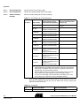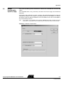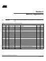
1
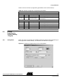
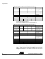
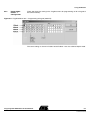
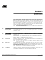
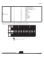
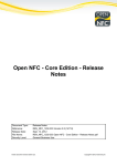
Long-range UHF RFID Demo Kit for IDIC TAGIDU ATA5590 .............................................................................................. User Manual Table of Contents Section 1 Reader Demo Kit Description ............................................................... 1-1 Section 2 Getting Started...................................................................................... 2-1 2.1 2.2 2.3 2.4 Built-up Hardware .....................................................................................2-1 Driver Installation ......................................................................................2-2 Starting the Demo Software for the First Time..........................................2-4 The First Communication Between the Tag and the Reader ....................2-5 Section 3 Hardware Description ........................................................................... 3-1 Section 4 Software Description............................................................................. 4-1 4.1 Menu Options............................................................................................4-2 Section 5 Operation .............................................................................................. 5-1 5.1 Reader Configuration ................................................................................5-1 5.1.1 Read/Write Mode................................................................................5-2 5.1.2 Tags....................................................................................................5-2 5.1.3 Trigger Mode ......................................................................................5-2 5.1.4 Output Control ....................................................................................5-3 5.1.5 Buzzer ................................................................................................5-3 5.1.6 Tag Options ........................................................................................5-3 5.1.7 Temperature Sensor...........................................................................5-3 5.1.8 HF Settings.........................................................................................5-3 5.1.9 Listen Before Talk Options .................................................................5-3 5.1.10 Options ...............................................................................................5-3 5.1.11 Get Configuration ...............................................................................5-4 5.1.12 Set Configuration................................................................................5-4 5.1.13 Reset to Factory Settings ...................................................................5-4 5.2 Reader Configuration Options (Tags) .......................................................5-5 5.2.1 Rules ..................................................................................................5-6 5.2.2 Start Address (hex).............................................................................5-6 5.2.3 Anticollision Start Address (hex).........................................................5-6 Long-range UHF RFID Demo Kit User Manual i 4910B–RFID–04/06 Table of Contents 5.2.4 Mask Length (dec)..............................................................................5-6 5.2.5 Selection Mask ...................................................................................5-6 Section 6 Memory Organization ........................................................................... 6-1 6.1 6.2 Overview ...................................................................................................6-1 Summary...................................................................................................6-2 6.2.1 ATA5590: Readable and Writable Transponder.................................6-2 6.2.2 ATA5590 with UID: Readable and Writable Transponder ..................6-2 Section 7 UID: Atmel Secure Locked Programmed ID ......................................... 7-1 7.1 UID Organization ......................................................................................7-1 7.1.1 7.2 7.3 Traceability Data.................................................................................7-1 UID Arbitration ..........................................................................................7-2 CRC5 Calculation .....................................................................................7-3 Section 8 Using the Reader.................................................................................. 8-1 8.1 8.2 Introduction ...............................................................................................8-1 Polling Mode .............................................................................................8-1 8.2.1 Read ...................................................................................................8-1 8.2.2 Write ...................................................................................................8-2 8.2.3 Inventory.............................................................................................8-3 8.2.4 LOCK Block ........................................................................................8-3 8.3 8.4 Report Mode .............................................................................................8-4 ID Page Programming (System Memory – Page 0)..................................8-5 8.4.1 Polling Mode.......................................................................................8-5 8.4.2 Report Mode: Reader –> Configuration .............................................8-7 Section 9 Arbitration ............................................................................................. 9-1 9.1 9.2 ii 4910B–RFID–04/06 Arbitration in Polling Mode ........................................................................9-1 Arbitration in Report Mode ........................................................................9-1 9.2.1 Anticollision.........................................................................................9-1 9.2.2 Single Shot .........................................................................................9-1 9.2.3 Tag Options ........................................................................................9-1 9.2.4 Read Cycles .......................................................................................9-2 Long-range UHF RFID Demo Kit User Manual Table of Contents Section 10 Additional Information ......................................................................... 10-1 Section 11 Error Handling/FAQ ............................................................................ 11-1 11.1 Problem...................................................................................................11-1 11.1.1 Actions..............................................................................................11-1 Section 12 Appendix............................................................................................. 12-1 Long-range UHF RFID Demo Kit User Manual iii 4910B–RFID–04/06 Section 1 Reader Demo Kit Description This UHF reader demo kit supports wireless data transmission of Atmel's passive RFID IDIC® ATA5590, operating in the ISM frequency bands. Typical applications for this passive transponder device are supply chain, asset control, toll collection, or pallet tracking. The kit contains a UDL500 long-range UHF reader from deister electronic GmbH, an interface converter, a power supply, and all other necessary components such as cables, a label set with different antennas (30 antennas in all) and the software required to build up a working UHF reader system. The reader system is available for the European ISM frequency band (ETSI compliant) and for the North American ISM frequency band (FCC compliant). Order code for the European ISM-band-compatible reader (ETSI): ATAK559001-8 Order code for the American ISM-band-compatible reader (FCC): ATAK559001-9 Figure 1-1. Reader Demo Kit Long-range UHF RFID Demo Kit User Manual 1-1 4910B–RFID–04/06 Reader Demo Kit Description Demo Kit Content: 1 UHF reader with 2 integrated antennas Label and tag set with TAGIDU™ ATA5590 (~30 parts) 1 SNG3 (interface converter: USB to RS485) 1 power supply 12V DC/240V AC (FCC version: 12V DC/110-240V AC) 1 USB cable 1 CD-ROM, Demo Software 1 Floppy disk containing drivers 1-2 4910B–RFID–04/06 Long-range UHF RFID Demo Kit User Manual Section 2 Getting Started 2.1 Built-up Hardware Figure 2-1 shows the correct assembly of the SNG3 USB converter. The TX LED indicates that the PC is sending command frames to the reader, and the RX LED shows that the reader is answering or sending the status back to the PC. Figure 2-1. Built-up Hardware (SNG3 USB Converter) Long-range UHF RFID Demo Kit User Manual 2-1 4910B–RFID–04/06 Getting Started 2.2 Driver Installation Before getting started, two hardware drivers, the USB-RS485 Converter and the USB Serial Port, have to be installed. The following steps describe the installation. 1. Plug the USB cable into the PC. 2. Normally, the USB-RS485 converter is automatically detected by the system. If this doesn’t happen, the search for hardware can be started manually by clicking: Start -> Settings -> Control Panel -> System -> Hardware -> Device Manager. Select USB Serial Port (which is marked by a yellow question mark, indicating that the hardware is not correctly installed). 3. A message window will pop up indicating the beginning of the installation of the driver for the USB-RS485 converter. To continue the installation, click Next. 4. To have the installer search for a suitable hardware driver, choose Search for a suitable driver for my device (recommended). 5. Insert the floppy disk into the floppy drive and in the Optional search locations menu select the item Floppy disk drives. The system will now search for the driver in the root directory of the floppy. The first installation will be the USB-RS485 Converter, see Figure 2-2. Figure 2-2. Driver File Search Result for the USB-RS485 Converter When the installation is finished, a message will appear stating that the installation of the USB serial converter was successful. 6. A second driver is needed for successful communication between the reader and PC, the USB Serial Port (see Figure 2-3). The procedure for the USB serial port installation is the same as for the USB-RS485 converter. 2-2 4910B–RFID–04/06 Long-range UHF RFID Demo Kit User Manual Getting Started Figure 2-3. Driver Search Result for the USB Serial Port Installation When the installation is finished, a message will appear stating that the installation of the USB serial port was successful. 7. After installing the drivers, the PC has to be rebooted. Long-range UHF RFID Demo Kit User Manual 2-3 4910B–RFID–04/06 Getting Started 2.3 Starting the The first time the demo software is started, settings such as port selection, baud rate, reader address, etc. have to be set. Demo Software for the First Time Port selection: Select the port being used to communicate with the reader in the Port menu. If the port is unknown, choose Special functions -> Search for serial ports to scan all active COM ports on the host computer. Another possibility is to use the information provided by the OS, by selecting Start -> Settings -> Control Panel -> System -> Hardware -> Interface to determine which USB COM port the SNG3 adapter is attached to. The first indication of proper communication between the reader and the host is a message from the reader. This can be observed in the Monitor window. Messages displayed in green are from the host to the reader, and red messages are from the reader to the host. Baud rate: The baud rate can be changed by browsing View -> deBus Polling and selecting scan settings. The baud rate setting can be changed as required by the reader device. Note: If communication between the reader and host fails even though the correct COM port has been selected, it could be that the reader and the host have different baud rate settings, preventing communication. It is possible to run a scan to discover the baud rate being used by the reader device by selecting View -> deBus Polling -> scan settings -> baudrate -> all (no specific baud rate is selected), and clicking the button detect reader(s). If the host finds a baud rate where communication with the reader device is possible, the result of the scan is displayed under detected readers. Now there are two options: 1. Confirm that this reader and the settings detected (especially the baud rate) should be used by clicking the button set as current reader. 2. Change the baud rate of the reader device by clicking the button configure. These are the primary settings for communication between the reader device and the host PC. If, during or after power on, communication is not or is no longer possible, check these settings in the demo software and follow the steps above. 2-4 4910B–RFID–04/06 Long-range UHF RFID Demo Kit User Manual Getting Started 2.4 The First Communication Between the Tag and the Reader This section outlines the capabilities of the system, and how to establish communication between the tag and host via the reader device. Browsing to the menu Reader -> Configuration opens a new window, reader configuration. In this new window it is possible to set the main settings for the RF link, such as tag protocol selection, RF power, read/write mode, arbitration mode, trigger mode, etc. Here is an example to get you started: Arbitration on the UID of the ATA5590 (see Section 7). 1. Tags (Protocol Selection) Select the menu item Reader -> Configuration, then under the option tags choose the protocol TAGIDU/ATA5590 with UID 2. Trigger Mode Select no trigger mode (default setting) 3. Output Control Select none (default setting) 4. Buzzer Select either off (default setting) or the read setting, which causes the buzzer to sound when reading is successful 5. Tag Options Set Tag timeout to 10 ms (for this example it doesn't matter) 6. Temperature Sensor Select 80°C (default setting) 7. RF Settings The RF power is adjustable in 10 steps (from 4W EIRP to 0.10W ERP) (for this example it doesn't matter, any RF setting can be selected) 8. Options Select options arbitration and report mode 9. Set Configuration Confirm this configuration by clicking the button Set configuration 10. RF ON The RF power of the reader device can be controlled via the menu RF Interface. The option RF ON switches on the RF power of the reader, making it possible to communicate with the tag. Verification that the tag is reading, writing or arbitrating can also be observed on the reader itself; the yellow and green LEDs will light if there is communication, see Section 3. Long-range UHF RFID Demo Kit User Manual 2-5 4910B–RFID–04/06 Getting Started The result of the arbitration or read is displayed in the Transponder data window, here is an example: ID 98FF00A70BF1 UID from the tag 2-6 4910B–RFID–04/06 Protocol Read counter [TAGIDU/ATA5590 with UID] (2) ATA5590 with arbitration on Indication of how often the tag the UID has been read Long-range UHF RFID Demo Kit User Manual Section 3 Hardware Description The reader has three LEDs and one alarm that can be used to show if the reader is ready to receive and if a tag has been read. LEDs Reader Status Yellow: on Red and green: off Reader is active, no read or write currently occuring, RF on Yellow and red: on Green: off Reader is active but RF is off; therefore, no communication is possible between the tag and reader Yellow and green: on Red: off Reader is active and RF is on; there is ongoing communication between the tag and reader (read, write or arbitration) Green and red: on Yellow: off Reader reset or powered up, RF off; system not ready for communication Red: blinking and alarm sounding Green and yellow: off Malfunction Long-range UHF RFID Demo Kit User Manual 3-1 4910B–RFID–04/06 Section 4 Software Description Figure 4-1 shows the standard window after successful installation of the reader demo software. The window consists of a menu, a shortcut list, a status bar, and a work space. Figure 4-1. Graphical User Interface (GUI) of the Demo Software Long-range UHF RFID Demo Kit User Manual 4-1 4910B–RFID–04/06 Software Description 4.1 Menu Options This section gives an introduction to the demo software, the menu bar, and the submenus. Figure 4-2. Menu Bar 1. File Exit Exit the demo software 2. Port COM X Select the port to be used for communication; all available and installed ports are displayed TCP/UDP ---- Disconnect Connects or disconnects the communication link between the PC and reader deBus Standard settings for the deister reader use BCC When activated, a block check character (BCC) is transmitted for data validation; these settings are ignored if deBus is selected show ASCII When activated, the transponder’s data is displayed in ASCII format 3. Reader Soft trigger ON Active a software trigger on command Soft trigger OFF Deactivates the trigger if the reader is in trigger mode and the software trigger is activated Version request Get the current reader firmware version information Configuration Menu options for the operation settings of the reader (see also Section 5.1) Diagnostics Activates the diagnosis function and displays all relevant reader data: – Temperature at the power amplifier – The current configuration for the power setting – Current configuration for the modulation depth – The minimum, the average, and the maximum noise level measured by the reader 4-2 4910B–RFID–04/06 Long-range UHF RFID Demo Kit User Manual Software Description Output ON Activates the switching output from the reader Output OFF Deactivates the switching output from the reader Poll command Queries new messages from the reader devices in bus mode Mode – Polling mode: The reader has to ask the host to transmit data – Report mode: The reader works independently, meaning the reader does not have to ask the host to transmit data to the tags Send reset This command restarts the reader, equivalent to a power-on reset 4. Transponder Read Setting of the read address and length of the data to be read out Write Setting of the write address and the storage information, see Section 6 Inventory This command queries the serial numbers of all transponders within antenna range and reports those numbers Lock block This command is used to change the lock status of a transponder Write AFI The application family identifier (AFI) content can be written or modified (disabled for the ATA5590) EPC read Disabled for the ATA5590 EPC write Disabled for the ATA5590 Tag functions Disabled for the ATA5590 5. RF Interface RF ON RF power on RF OFF RF power off RF reset The RF field will be switched off for 100 ms 6. Special Function Special functions Provides a command line to send commands to the reader device in the protocol frame Note: On the command line, the commands must be entered as hex values. The deBus protocol automatically adds the initial sequence “FFFF” and the end sequence “FE” to the data entered, and sends the command to the reader device. clear list of transponders’ serial numbers Clears all detected serial numbers in the demo software Search for serial ports Scans all available serial ports on the host, and displays the result in a list when finished Long-range UHF RFID Demo Kit User Manual 4-3 4910B–RFID–04/06 Software Description 7. Options Block Data Representation Display hex – Data representation in hex format Display ASCII – Data representation in ASCII format EPC Representation Display decimal numbers – Display the transponder data in decimal format 8. View Setting Toolbar Frequently used functions can be provide by icons in the tool bar. To customize the application, you can add shortcuts to the toolbar. Also, a Monitor work space can be add to the default work spaces Large Icons Large or normal icon representation Toolbar Align Top Bottom Left Right Buttons Inventory RF ON RF OFF RF reset Security Read Write Diagnostics Noise monitor deBus Poll command Read EPC Write EPC Show buttons captions Button captions on/off Clear all windows Clears the information in the following windows: Transponder data reader status and Monitor Arrange windows All displayed monitors are uniformly aligned in the work space Show monitor 4-4 4910B–RFID–04/06 The protocol transferred between PC and the reader can also be observed by activating the Monitor window. Clicking this makes the Monitor window appear Long-range UHF RFID Demo Kit User Manual Software Description deBus polling Configuration menu for the deBus polling mode Show routing panel Displays the routing panel in the menu bar Show reader diagnostic window Displays the reader diagnostic window in the work space Noise Monitor Displays the RMS value of the receiver sensitivity for information about the noise affecting the RX input FFT window Displays an FFT window, to show the spectrum of the ISM band Long-range UHF RFID Demo Kit User Manual 4-5 4910B–RFID–04/06 Section 5 Operation This section provides general information regarding the operation of the UDL500 longrange reader. 5.1 Reader Configuration To configure the reader’s main settings, select the configuration window (Reader -> configuration), see Figure 5-1. Long-range UHF RFID Demo Kit User Manual 5-1 4910B–RFID–04/06 Operation Figure 5-1. Reader Configuration Menu 5.1.1 Read/Write Mode Select between read or write mode, see Section 8-3. 5.1.2 Tags Select the protocol from the list (the TAGIDU protocol is the default selection). 5.1.3 Trigger Mode If trigger mode is activated, the reader only becomes active after being triggered by a hardware or software trigger. When the reader is not active, the UHF carrier is switched off and the reader waits for the next trigger. After becoming active, the reader first carries out LBT or frequency hopping before starting to read. Note: A software trigger can only be reset by software or, in EN300220 mode, by the defined active time. Four different hardware trigger events are possible: read while high level applied read for a defined period of time after rising edge read for a defined period of time after falling edge anticollision trigger (same as inventory, see the protocol specification) If the reader is operated as a stand-alone reader, select no trigger. 5-2 4910B–RFID–04/06 Long-range UHF RFID Demo Kit User Manual Operation 5.1.4 Output Control If output mode is activated, the reader sets or resets its digital output in four different ways: set output low after tag read set output low after no read set output high after tag read set output low after no read Output mode is only available when trigger mode is activated. The length of time the output is set to high or low level can be modified. The value is a multiple of 6.5 ms and has a tolerance of 6.5 ms. If the reader is operated as a stand-alone reader, select none. 5.1.5 Buzzer Disabled, or only by reading a tag. 5.1.6 Tag Options Tag timeout defines the number of anticollision commands before a reset is sent. If this value is “0” the reader will never send a reset command to the tags. 5.1.7 Temperature Sensor The threshold level for temperature can be adjusted. The temperature has a precision of 0.25°C per step. 5.1.8 HF Settings RF-Power: 10 different steps to adjust the output power of the reader, see Table 5-1. Read cycles: Defines how many anticollision commands are sent before the next select command is sent. 5.1.9 Listen Before Talk Options Int LBT / hopping: The time interval between the LBT measurements can be configured in steps of 1 ms. The inactive time is always at least 100 ms. Channels: see Table 5-1. 5.1.10 Options Under option, the arbitration options can be set. anticollision: Activate the anticollision function. Note: SNR (page0 in the control memory) in the address selection bar indicates the serial number of the transponder. singleshot: If single shot mode is selected and a transponder stays in the read range for a longer time, the serial number of this transponder will be transmitted again after the time specified in tag time-out. The value is a multiple of 100 ms. If tag time-out is set to 0, the serial number will not be transmitted again. Note: Single shot mode is not available in anticollision or portal mode! fast mode: ETSI compliant reader, fast mode shall be disabled for FCC compliant reader it is vice verse, see Table 5-2. report mode: by activation of the report mode the reader device send self-dependent telegram to the host system. If this option is deactivated, the reader is in the “OnLine mode” and answers on each request from the host system (bus operation mode). selftest: To test the reader for proper operation there is an integrated self test. This self test is done every time the reader is reset. During the self test the reader checks the functionality of its components. If there is a problem the reader’s red LED will start start blinking, and the alarm will sound. Note: Not every component can be checked by the self test. Long-range UHF RFID Demo Kit User Manual 5-3 4910B–RFID–04/06 Operation 5.1.11 Get Configuration Get the current status of the reader. 5.1.12 Set Configuration Confirm the setting configuration of the reader. 5.1.13 Reset to Factory Settings Reset all reader settings to the factory settings. Table 5-1. HF Setting and Channel Selection RF Power Note: Output Power Listen Before Talk Options – Frequency Hopping – North Channel Selection Versus American Radio Regulation European Radio Regulations (FCC part 15) 4W EIRP (US) Channel 0 to 9 FCC part 15 with 50 available channels 2W ERP Channel 0 to 9 – (compliant with EN 302 208) --- 1.75W ERP Channel 0 to 9 – (compliant with EN 302 208) --- 1.5W ERP Channel 0 to 9 – (compliant with EN 302 208) --- 1.25W ERP Channel 0 to 9 – (compliant with EN 302 208) --- 1W ERP Channel 0 to 9 – (compliant with EN 302 208) --- 0.75W ERP Channel 0 to 9 – (compliant with EN 302 208) --- 0.5W ERP Only channel 10 and 11 – (compliant with EN 300 220) or --channel 0 to 11 – (compliant with EN 302 208) 0.25W ERP Only channel 10 and 11 – (compliant with EN 300 220) or --channel 0 to 11 – (compliant with EN 302 208) 0.1W ERP Only channel 10 and 11 – (compliant with EN 300 220) or --channel 0 to 11 – (compliant with EN 302 208) Supported regulations: 1. ETSI EN 302 208: 10 available channels (865.6 to 867.6) with a maximum output power of 2W ERP, and 12 channels at a maximum output power of 500 mW ERP. Channel bandwidth: 200 kHz 2. ETSI EN 300 220: With one available channel at 869.5 MHz and a maximum output power of 500 mW ERP. Channel bandwidth: 250 kHz 3. FCC part 15: 50 available channels (902 MHz to 928 MHz) with a maximum output power of 4W EIRP. Channel bandwidth: 500 kHz For the European radio regulations the internal channel step is 100 kHz and for the North American regulation the internal channel step is 125 kHz; therefore, for the FCC part, every 4th channel is used (the FCC part has 200 internal channels and the ETSI part has 24 internal channels). Table 5-2. Fast Mode 5-4 4910B–RFID–04/06 Tag Data Rate Fast Mode Data Rate Slow Mode ATA5590 32 Kbit/s (US only – FCC 915 MHz) 16 Kbit/s (Europe only – ETSI 868 MHZ) Long-range UHF RFID Demo Kit User Manual Operation 5.2 Reader Configuration Options (Tags) This section provides general information to arbitrate the ATA5590 with the UDL 500 reader. The ATA5590 allows using a memory area other than the ID page for anticollision arbitration. The length of the arbitration is always 16 bytes. The arbitration decrements from the selected start address. For example, if you choose block 6 as start address, the arbitration will be made over block 6 and block 5. The start address is the same as the address for read and write accesses. Note: This function is not available if the tag type ATA5590 with UID is selected. That type always does an arbitration over the lower six bytes of block 20, which contain the UID. Figure 5-2. Arbitration Option Menu Long-range UHF RFID Demo Kit User Manual 5-5 4910B–RFID–04/06 Operation 5.2.1 Rules There are four different rules for selection: 0: equal (EQ): Selection Mask must be equal to the transponder memory 1: lower than or equal to (LTE): Selection Mask must be lower than or equal to the value in the transponder memory 2: equal (EQ): Selection Mask must be equal to the transponder memory 3: greater than or equal to (GTE): Selection Mask must be greater than or equal to the value in the transponder memory 5.2.2 Start Address (hex) Defines the memory start address for the selection. If “0” is chosen, the selection is made over the 12 lower bytes of the ID page. The start address is the same address as used for read or write accesses. Block size is eight bytes. 5.2.3 Anticollision Start Address (hex) It is also possible to arbitrate over a memory area other than the ID page. Anticollision start address defines the start address for arbitration as a block address with block size of 8 bytes. This is the same address format as for the read block and write block commands. The length of the arbitration is always 16 bytes. Note: If the tag type ATA5590 with UID is selected, it is not possible to make the arbitration over a memory area other than the UID. 5.2.4 Mask Length (dec) If the value of the selection mask length is “0”, no selection command is sent by the reader. 5.2.5 Selection Mask This mask defines which of the 16 bytes in the selection mask is used for comparison. A “1” in the byte mask will activate the comparison for the corresponding selection mask byte. Bit number 7 of the byte mask corresponds to the first byte of the selection mask and bit number 0 corresponds to the last byte of the selection mask. 5-6 4910B–RFID–04/06 Long-range UHF RFID Demo Kit User Manual Section 6 Memory Organization 6.1 Overview Table 6-1 shows the memory addresses of the ATA5590 which can be addressed by the reader. Table 6-1. Reader Implementation of Memory Organization Memory Organization Address Blocks Memory Size 0 1 64 bits/8 bytes 1 1 64 bits/8 bytes 2 1 64 bits/8 bytes 3 1 64 bits/8 bytes 4 1 64 bits/8 bytes 5 1 64 bits/8 bytes 6 1 64 bits/8 bytes 7 1 64 bits/8 bytes 8 1 64 bits/8 bytes 9 1 64 bits/8 bytes 10 1 64 bits/8 bytes 11 1 64 bits/8 bytes 12 1 64 bits/8 bytes 13 1 64 bits/8 bytes 14 1 64 bits/8 bytes 15 1 64 bits/8 bytes 16 1 64 bits/8 bytes 17 1 64 bits/8 bytes 18 1 64 bits/8 bytes Lock Block Comment User Memory Page 0 (bit 64 to bit 1) X Lock bit (MSB) Page 0 (bit 128 to bit 65) X Page 1 (bit 64 to bit 1) X Lock bit (MSB) Page 1 (bit 128 to bit 65) X Page 2 (bit 64 to bit 1) X Lock bit (MSB) Page 2 (bit 128 to bit 65) X Page 3 (bit 64 to bit 1) X Lock bit (MSB) Page 3 (bit 128 to bit 65) X Page 4 (bit 64 to bit 1) X Lock bit (MSB) Page 4 (bit 128 to bit 65) X Page 5 (bit 64 to bit 1) X Lock bit (MSB) Page 5 (bit 128 to bit 65) X Page 6 (bit 64 to bit 1) X Lock bit (MSB) Page 6 (bit 128 to bit 65) X Page 7 (bit 64 to bit 1) X Lock bit (MSB) Page 7 (bit 128 to bit 65) X Lock bit (MSB) Page 0 (ID page: bit 64 to bit 1) X Page 0 (ID page: bit 128 to bit 65) X Page 1 (User system info: bit 64 to bit 1) 19 1 64 bits/8 bytes Lock bit (MSB) Page 1 (User system info: bit 128 to bit 65) Note: Most significant bit (MSB) always indicates the upper bit Long-range UHF RFID Demo Kit User Manual System Memory X X 6-1 4910B–RFID–04/06 Memory Organization 6.2 Summary 6.2.1 ATA5590: Readable and Writable Transponder Memory 128 bytes user memory + 40 bytes system memory including 16 bytes tag id Length of serial number 128 bits = 16 bytes Length of serial number for block write and block read commands 16 bytes Block size read 8 bytes Block size write 4 or 8 bytes Block size lock and query lock 8 bytes Note: 6.2.2 ATA5590 with UID: Readable and Writable Transponder Although the block size is 8 bytes, the lock and query-lock operation is performed across 16 bytes. Serial number Stored in Blocks 16 and 17, see Table 6-1. Memory 128 bytes user memory + 40 bytes system memory Length of serial number 48 bits = 6 bytes Length of serial number for block-write and block-read commands 6 bytes Block size read 8 bytes Block size write 4 or 8 bytes Block size lock and query lock 8 bytes Note: Although the block size is 8 bytes, the lock and query-lock operation is performed across 16 bytes. Serial number 6-2 4910B–RFID–04/06 Stored in Blocks 16 and 17, see Table 6-1. Long-range UHF RFID Demo Kit User Manual Section 7 UID: Atmel Secure Locked Programmed ID The traceability data is an ID, or number, provided by Atmel which can be used be the user as a unique ID (UID). The traceability data blocks are programmed and locked by Atmel during the production test. After sawing, the data content can’t be changed. This process is irreversible! 7.1 UID Organization Table 7-1. UID Page in the Control Memory (Page 2) RFU 24 23 22 21 20 19 18 Tag type RFU TUNE EAS ... 31 32 30 29 IC rev. number LOTID number CRC5 ... RFU 31 32 30 24 23 ... 14 13 LOTID character Wafer number 21 20 ... ... 0 LOTID number Die number 16 15 ... 0 The UID page (see Table 7-1 and also Table 12-1), consists of 48 bits of manufacturer data reporting the production lot, and 16 status bits. The manufacturer data includes a lot ID character and a 5-digit lot number. 7.1.1 Traceability Data LOTID character: Lot character. Example: Z LOTID number: 5-digit lot number. Example: 13711 Wafer number: 2-digit wafer number. Example: 12 Die number: Die per wafer. Example: 3512 CRC5: Cyclic redundancy check (CRC5) – 5 bits to check the data content after programming the UID in the EEPROM Long-range UHF RFID Demo Kit User Manual 7-1 4910B–RFID–04/06 UID: Atmel Secure Locked Programmed ID 7.2 UID Arbitration The ATA5590 has the capability of arbitrating over memory areas other than the ID page. The arbitration length is always 16 bytes. It is also possible to arbitrate on the UID page of the ATA5590. This has some advantages for the end user; first, this ID can be used by the user – it is not necessary to program a new ID in page 0 in the control memory. Second, it is possible in the field to program virgin tags which have no ID stored in page 0 in the control memory. Therefore it is possible to select each tag, no matter how it is necessary to program an ID. Note: If the tag type ATA5590 with UID is selected, it is not possible to arbitrate over a memory area other than the UID. The UID arbitration can be selected via the menu Reader -> Configuration, see Section 5-1 and Figure 7-1. Figure 7-1. Selection for the TAGIDU UID Arbitration Table 7-2. Example Using ArbitrationTAGIDU/ATA5590 with UID, UID Number Shown (Transponder Data Window): 98EE001810AA Hex value Description EAS RFU Tag type 00 EE IC rev. LOTID character 18 LOTID number 10 AA 0 0 0 0 0 0 0 0 0 0 0 1 1 0 0 0 0 0 0 1 0 0 0 0 1 0 1 0 1 0 1 0 RFU TUNE Description 98 0 0 0 0 0 0 0 0 0 0 0 0 0 1 1 0 1 0 0 1 1 0 0 0 1 1 1 0 1 1 1 0 Hex value Binary value 06 TUNE Binary value 00 CRC5 LOTID number Wafer number Die number UID summary (overall): LOTID character: Z (hex value: 1A; binary value: 11010) LOTID number: 51056 (hex value: C770; binary value: 01100011101110000) Wafer number: 24 (hex value: 18; binary value: 11000) Die number: 4266 (hex value: 10AA; binary value: 0001000010101010) The compete UID page in the control memory can be read out using a read command. 7-2 4910B–RFID–04/06 Long-range UHF RFID Demo Kit User Manual UID: Atmel Secure Locked Programmed ID 7.3 CRC5 Calculation CRC5 is a security feature for checking the data contents after programming the UID in the EEPROM. The CRC5 value is stored non-inverted in the memory. The calculation of the CRC5 value includes the LOTID character, LOTID number, wafer number, and die number, see Figure 7-2. Figure 7-2. CRC5 Calculation Long-range UHF RFID Demo Kit User Manual 7-3 4910B–RFID–04/06 Section 8 Using the Reader 8.1 Introduction The reader can be operated in two different modes: Polling mode Report mode The mode can be changed via the menu Reader -> Mode. When Report mode is selected, if the reader is in arbitration mode it continuously reads (or scans) tags which are in the reader’s range. Polling mode allows the host to fully control the reader. This means that the reader is told by the host which command or information to transmit. 8.2 Polling Mode While in polling mode there are four commands in the Transponder menu for communication with the tags: Read, Write, Inventory, and Lock Block. 8.2.1 Read The Read command enables the interrogator to read out all memory areas of the ATA5590 and the traceability data or UID of the tag (this option is only enabled in polling mode). A shortcut item can be created under the menu item View –> Buttons –> Read. Figure 8-1. Read Command, Polling Mode Long-range UHF RFID Demo Kit User Manual 8-1 4910B–RFID–04/06 Using the Reader Table 8-1. Block Number Number of Blocks Comment 0 to 20 Min. 1 21 × 64 bits = 1344 bits 0 to 3 Max. 18 (4 × 64 bits) + (17 × 64 bits) = 1344 bits tag type Protocol selection serial No All detected tags are listed here with their unique ID. To interrogate a transponder, the serial number must first be known. Note: 8.2.2 Write Clears all detected serial numbers in the demo software The Write command enables the interrogator to read out all memory areas of the ATA5590, plus the traceability data or UID of the tag (only enabled in Polling mode). A shortcut item can be created under the menu item View –> Buttons –> Write. Figure 8-2. Write Command, Polling Mode Table 8-2. Block Number Number of Blocks Block Size [Byte] 0 to 39 Min. 1 Min. 4 40 × 32 bits = 1280 bits 0 to 22 Max. 18 Min. 4 (23 × 32 bits) + (17 × 32 bits) = 1280 bits 0 to 19 Min. 1 Max. 8 20 × 64 bits = 1280 bits 0 to 2 Max. 18 Max. 8 (3 × 64 bits) + (17 × 64 bits) = 1280 bits tag type Protocol selection serial No All detected tags are listed here with their unique ID. To interrogate a transponder, the serial number must first be known. Note: 8-2 4910B–RFID–04/06 Comment Clears all detected serial numbers in the demo software Long-range UHF RFID Demo Kit User Manual Using the Reader 8.2.2.1 Data AutoFill to fit block size: – Off: turn off the automatic function to fill with zeros (the data size must be exactly the same as the desired block size) – leading 0s: fill with zeros before the provided data (if the data size is not the desired block size) – trailing 0s: fill with zeros after the provided data (if the data size is not the desired block size) 8.2.3 Inventory The command Inventory tries to detect the serial numbers of all transponders within the range of the reader as the tags transmit their serial numbers. A shortcut item can be created under the menu item View –> Buttons –> Inventory. 8.2.4 LOCK Block LOCK command is used to lock or read out the security status to get write permission for specified blocks. The action LOCK block is irreversible. A shortcut item can be created under the menu item View –> Buttons –> Security. Figure 8-3. Lock Command, Polling Mode GET security status Determines the actual block security status. LOCK block Sets the lock bit of a page. Note: This action is irreversible. block No Block/page selection for locking, see Table 6-1. tag type Protocol selection serial No All detected tags are listed here with their unique ID. To interrogate a transponder, the serial number must first be known. Note: Clears all detected serial numbers in the demo software Long-range UHF RFID Demo Kit User Manual 8-3 4910B–RFID–04/06 Using the Reader 8.3 Report Mode Report mode can either be activated via the menu Reader –> Mode –> Switching to report mode or Reader –> configuration –> options (by selecting report mode). In this mode the reader works independently from the host, meaning that the reader works continuously (read; anticollision in write mode; if there is a successful write, the reader stops the transmission). In 1 block, 64 bits can be written or read out of the EEPROM, see Table 8-3 and Table 8-4. Table 8-3. Reader Configuration Setting, Read Command Command: READ Address Range Blocks Comment SNR – 20 Min. 1 21 × 64 bits = 1344 bits SNR – 12 Max. 9 (13 × 64 bits) + (8 × 64 bits) = 1344 bits The maximum number of bits which can be read out is 576 bits (64 bits × 9 blocks = 576 bits). The upper address range when reading 9 blocks is 13. The minimum number of bits that can transferred are 64 bits (1 block), the upper address range is thus 21. Table 8-4. Reader Configuration Setting, Write Command Command: WRITE Address Range Blocks Comment 0 – 19 Min. 1 20 × 64 bits = 1280 bits 0 – 16 Max. 4 (17 × 64 bits) + (3 × 64 bits) = 1280 bits In write mode, the maximum number of bits which can be transferred is 256 bits (64 bits × 4 blocks = 256 bits, see Figure 8-4), the upper address range is 16. The minimum number of transferred bits and also the address range is the same as in read mode. Figure 8-4. ProgData in the Reader Configuration Menu – Programming Data 8-4 4910B–RFID–04/06 Long-range UHF RFID Demo Kit User Manual Using the Reader Table 8-5 shows the write or programming possibilities for the control memory. Table 8-5. Reader Configuration, Programming Possibilities Write to System Memory Option 1 Address Blocks Memory Size Comment 16 2 128 bits/16 bytes Page 0 (ID page) – System memory 16 4 256 bits/32 bytes Page 0 and 1 (ID page + User system info) – System memory Option 2 8.4 ID Page Programming (System Memory – Page 0) 8.4.1 Polling Mode Address Blocks Memory Size Comment 16 1 64 bits/8 bytes Page 0 (ID page) – System memory 17 1 64 bits/8 bytes Page 0 (ID page) – System memory 18 1 64 bits/8 bytes Page 1 (User system info) – System memory 19 1 64 bits/8 bytes Page 1 (User system info) – System memory Figure 8-5 shows an example of the WRITE command in polling mode programming an ID in page 0 of the control memory, see Table 8-6 and Table 8-7 on page 6. Figure 8-5. Example of Programming an ID in Polling Mode Long-range UHF RFID Demo Kit User Manual 8-5 4910B–RFID–04/06 Using the Reader Table 8-6. ID-programming Example, Polling Mode; Block Size = 8 Data Comments Number of blocks 1 1 Reader setting (ID can be programmed in 2 steps) Block size [bytes] 8 8 Reader setting Block number 16 17 Reader setting Number of blocks 2 Reader setting (ID can be programmed in 1 step) Block size 8 Reader setting Block number 16 Page address(1) --- Reader setting 0 (ID page: Control memory) Block address(2) 1 0 Physical address 3 2 Physical address (3) 12345678 Data format in hex 12345678 ABCDEF12 00000000 1. For the page address, see Table 12-1 2. For the block address, see Table 12-1 3. A description of the block configuration can be found in Table 12-1 Table 8-7. ID-programming Example, Polling Mode; Block Size = 4 Data Comments 1 Block size [bytes] 4 4 4 4 Reader setting Block number 16 17 17 Reader setting 16 1 1 Reader setting (ID can be programmed in 4 steps) Number of blocks 1 Number of blocks 2 2 Reader setting (ID can be programmed in 2 steps) Block size [bytes] 4 4 Reader setting Block number 17 Reader setting 16 Number of blocks 4 Reader setting (ID can be programmed in 1 step) Block size [bytes] 4 Reader setting Block number 16 Page address(1) 0 (ID page: Control memory) --- Block address(2) 1 0 Reader setting Physical address 3 2 Physical address (3) Notes: Note: 8-6 4910B–RFID–04/06 12345678 Data format in hex 12345678 ABCDEF12 00000000 1. For the page address, see Table 12-1 2. For the block address, see Table 12-1 3. A description of the block configuration can be found in Table 12-1 The memory contents can be protected with a lock bit – this operation is irreversible! The lock bit is located at the most significant bit (MSB) in Page 0 of the control memory (see Table 8-7). Therefore, the lock bit should be set in an additional step or as the last command during the programming of a page (applies to all pages in the system and user memory). Long-range UHF RFID Demo Kit User Manual Using the Reader 8.4.2 Report Mode: Reader –> Configuration Figure 8-6 shows the setting in the ProgData menu for programming an ID in Page 0 of the control memory. Figure 8-6. ProgData Menu Item – Programming of Page 0 (96-bit ID) The same settings as shown in Table 8-6 and Table 8-7 are also valid for Report mode. Long-range UHF RFID Demo Kit User Manual 8-7 4910B–RFID–04/06 Section 9 Arbitration The ATA5590 supports anticollision arbitration over memory areas other than the ID page. The length of the arbitration is always 16 bytes. The search algorithm used is deterministic (binary tree) arbitration (advantage: faster then Aloha). In Polling mode, up to 135 transponder serial numbers can be stored in the UDL reader device. If there is no polling command before the reader runs out of memory, new serial numbers will be lost. These serial numbers are filtered to avoid having the same serial number stored twice. Only one serial number will be transmitted in a message. Note: If the tag type ATA5590 with UID is selected, it is not possible to make the arbitration over another memory area than the UID! 9.1 Arbitration in Polling Mode The Inventory command (Transponder -> Inventory) tries to detect the serial numbers of all transponders within the range of the reader as the tags transmit their serial numbers (see Section 8.2.3). 9.2 Arbitration in Report Mode Arbitration in report mode can be adjusted via the menu item Reader -> Configuration, (see Section 5-1). Arbitration options are in the Configuration menu (see the explanation in Section 5-2). Selection: Reader -> Configuration (see also Section 5-1) 9.2.1 Anticollision Activate the anticollision function. The arbitration algorithm used is based on the binary tree or deterministic arbitration concept. Note: 9.2.2 Single Shot If single shot mode is selected and a transponder stays in the read range for a longer time, the serial number of this transponder will be transmitted again after the time specified in tag timeout. The Value is a multiple of 100 ms. If tag timeout is “0”, the serial number will not be transmitted again. Note: 9.2.3 Tag Options SNR (page 0 of the control memory) in the address selection bar indicates the serial number of the transponder. Single shot mode is not available in anticollision or portal mode! Tag timeout defines the number of anticollision commands before a reset is sent. If this value is “0”, the reader will never send a reset command to the tags. Long-range UHF RFID Demo Kit User Manual 9-1 4910B–RFID–04/06 Arbitration 9.2.4 Read Cycles This option defines how many anticollision commands are sent before the next select command is sent. Selection: Reader -> Configuration -> Options (see Section 5-2) This menu item is an extension to the normal arbitration. The ATA5590 can arbitrate on memory areas other than the ID page and with different selection rules. 9-2 4910B–RFID–04/06 Long-range UHF RFID Demo Kit User Manual Section 10 Additional Information Detailed information is available in the introductory document Einfuehrung_UDL500_em.pdf, on the CD from deister and included in the application kit. Some application notes from deister are also available on the CD. Reader information is in the Deister directory on the CD under the following paths. Reader Description: Product/13.56 MHz to transpondertechnology/UDL500 Product/13.56--868 technology/UHF_portal MHz 868 MHz LogIdent/868 MHz LogIdent/868 MHz passive passive transponder Protocol Description: Protocol/PROTOCOL_UDxxx_deBus_v1_10_GB.pdf Application Notes: Software /RDemo software for configuration the readers/application_note Software/RDemo software for configuration the readers/RDemo discription Software Update: Software/update software for readers Long-range UHF RFID Demo Kit User Manual 10-1 4910B–RFID–04/06 Section 11 Error Handling/FAQ 11.1 Problem No communication between PC and UDL 500 reader. 11.1.1 Actions Verify that the correct port is selected. If the correct port is selected and no communication is possible, check the current reader address. The current reader address can be adjusted in the demo software. (In the menu bar under the item View -> deBus Polling.) Check the scan settings: Verify that the correct baud rate is chosen. If the correct baud rate and address is unknown, set the baud rate setting to all. This setting tells the reader to scan all possible baud rates and addresses. All identified readers are displayed in the detected reader window. Choose the appropriate entry, and confirm with set as current reader. Long-range UHF RFID Demo Kit User Manual 11-1 4910B–RFID–04/06 Section 12 Appendix Table 12-1. Physical Address Description of the ATA5590 Control Memory Physical address Block address Byte2 Byte3 Byte1 Manufacturer System Info – Manufacturer System Info 8th byte 7th byte 3 2 1 0 LotID Number LotID Number LotID Number LotID Number LotID Number LotID Number LotID Number LotID Number LotID Number LotID Number LotID Number LotID Number LotID Number LotID Number LotID Character LotID Character LotID Character LotID Character LotID Character IC Rev. Nr. LotID # LotID # Traceability Data Structure – 2nd byte Traceability Data Structure – 1st byte Die Number Die Number Die Number Die Number Die Number Die Number Die Number Die Number Die Number Die Number Die Number Die Number Die Number Die Number Die Number Die Number Wafer Number Wafer Number Wafer Number Wafer Number Wafer Number LotID Number LotID Number LotID Number CRC5 CRC5 CRC5 CRC5 Wafer # 4 Traceability Data Structure – 5th byte die on wafer # User System Info User System Info User System Info User System Info User System Info User System Info User System Info User System Info User System Info User System Info User System Info User System Info User System Info ADMIN RFU AFI (ISO/IEC15962) 1 DSFID (ISO/IEC15962) 0 LotID # LC# 5 User System Info Lock Bit (User sys.) 0 LID CRC ApplicationFamily ApplicationFamily ApplicationFamily ApplicationFamily ApplicationFamily ApplicationFamily ApplicationFamily ApplicationFamily AccessMethod AccessMethod RFU DataFormat DataFormat DataFormat DataFormat DataFormat ID ID ID ID ID ID ID ID ID ID ID ID ID ID ID ID ID ID ID ID ID ID ID ID ID ID ID ID ID ID ID ID ID ID ID ID ID ID ID ID ID ID ID ID ID ID ID ID ID ID ID ID ID ID ID ID ID ID ID ID DSFID ID ID AFI ID ID DSFID_ISO ID DSFID_nAc ID PRIVATE LOCK ID PAGE 0 Upper Byte ID Lower Byte ID ID ID ID ID ID ID ID ID ID ID ID ID ID ID ID ID ID ID ID ID ID ID ID ID ID ID ID ID ID ID 0 LC# Traceability Data Structure – 3rd byte 6 die on wafer # 1 1 – Traceability Data Structure – 6th byte 7 User System Info 2 2 Crc5# 0h 0 8 User System Info - Admin 1 3 CRC5 0h TUNE RFU RFU 0 IC Rev. Nr. 0h Traceability Data Structure – 4th byte TUNE 2 TAG TYPE TAG TYPE RFU RFU RFU RFU RFU RFU EAS(0) EAS_en 1 3 Byte0 31 30 29 28 27 26 25 24 23 22 21 20 19 18 17 16 15 14 13 12 11 10 9 ProgNbyte (tag must be selected) Blocked after sawing Can be locked (when locked it can't be reprogrammed) - OTP mechanism 1: List of Application Family Identifiers are defined in ISO/IEC 15961. Long-range UHF RFID Demo Kit User Manual 12-1 4910B–RFID–04/06 Appendix Table 12-2. Description of Various Memory Areas in the Control Memory Tag Type (1:0) 0h: backscatter RF-powered tag 1h: backscatter battery-powered tag 2h: active tag, AM RSSI Manufacturer System Info 3h: active receiver 7th Byte, Page 2 IC Rev. Nr. (3:5) 0h: V2.1 1h: V2.1 ADMIN 16th Byte, Page 0 Lock ID Page: Locks the whole page. No change of the page possible after setting to “1” Private: If set to “1”, the user is using custom structure and flags. If set to “0”, the user is using the following flags. DSFID_nAC: If set to “1”, a DSFID info is stored at byte 0 of block 3. If set to “0”, the Allocation Class info is stored at byte 0 of block 3. DSFID_ISO: If set to “1”, the DSFID coding structure is not compliant with ISO15962 regulations. DSFID: Indicates whether the DSFID information is stored in the Tag ID page. The content is stored at byte 0 or byte 2 depending on DSFID_nAC. AFI: Indicates that the AFI is stored in the Tag ID page. The construction of AFI corresponds with ISO 18000-6 FDIS. LID: Indicates that a Tag ID has a size larger than 96 bits. The other bits can be stored from page 7 down to page 0 of the user memory CRC: Indicates that a CRC value is supported. The CRC value can be stored after the administration part (byte 2), if the location is not used for storing the DSFID value. Access Method (1:0) -> ISO/IEC15691 defined in 7.1.2.4 0h: no directory 1h: directory 2h: selfMappingTag 3h: RFU DSFID 13th Byte, Page 0 12-2 4910B–RFID–04/06 Data Format (4:0) -> ISO/IEC 15691 defined in 7.1.2.5 00h: noFormatted 01h: fulFeatured 02h: rootOidEncoded 03h: iso15434 04h: iso6523 05h: iso15459 06h: reserved 07h: reserved 08h: iso15961Combined 09h: ean-ucc 0Ah: di 0Bh: upu 0Ch: iata 0Dh to 1Fh: reserved Long-range UHF RFID Demo Kit User Manual Appendix AFI (7:4) 0 x x 0 1 2 3 4 5 6 7 8 9 A B C D E F AFI 14th Byte, Page 0 Note: AFI (3:0) 0 0 y y 0, y 0, y 0, y 0, y 0, y 0, y 0, y 0, y 0, y 0, y 0, y 0, y 0, y 0, y 0, y Meaning All families and sub-families All sub-families of family X Only the Yth sub-families of family X Proprietary sub-family only Transport Financial Identification Telecommunication Medical Multimedia Gaming Data storage Item management Express parcels Postal services Airline bags RFU RFU RFU x and y each represent any single-digit hexadecimal value between 1 and F Table 12-3. Physical Address Description of the Control Memory of the ATA5590 Physical address Block address Byte0 Byte1 8 7 6 5 4 3 2 1 0 2 1 0 Lock Bit 3 0 Byte2 Lock Bit 3 7 Byte3 31 30 29 28 27 26 25 24 23 22 21 20 19 18 17 16 15 14 13 12 11 10 9 2 1 0 Page can be locked (when locked it can't be reprogrammed) - OTP mechanism Note: Whole page usable for expanded ID Long-range UHF RFID Demo Kit User Manual 12-3 4910B–RFID–04/06 Atmel Corporation 2325 Orchard Parkway San Jose, CA 95131, USA Tel: 1(408) 441-0311 Fax: 1(408) 487-2600 Regional Headquarters Europe Atmel Sarl Route des Arsenaux 41 Case Postale 80 CH-1705 Fribourg Switzerland Tel: (41) 26-426-5555 Fax: (41) 26-426-5500 Asia Room 1219 Chinachem Golden Plaza 77 Mody Road Tsimshatsui East Kowloon Hong Kong Tel: (852) 2721-9778 Fax: (852) 2722-1369 Japan 9F, Tonetsu Shinkawa Bldg. 1-24-8 Shinkawa Chuo-ku, Tokyo 104-0033 Japan Tel: (81) 3-3523-3551 Fax: (81) 3-3523-7581 Atmel Operations Memory 2325 Orchard Parkway San Jose, CA 95131, USA Tel: 1(408) 441-0311 Fax: 1(408) 436-4314 RF/Automotive Theresienstrasse 2 Postfach 3535 74025 Heilbronn, Germany Tel: (49) 71-31-67-0 Fax: (49) 71-31-67-2340 Microcontrollers 2325 Orchard Parkway San Jose, CA 95131, USA Tel: 1(408) 441-0311 Fax: 1(408) 436-4314 La Chantrerie BP 70602 44306 Nantes Cedex 3, France Tel: (33) 2-40-18-18-18 Fax: (33) 2-40-18-19-60 ASIC/ASSP/Smart Cards 1150 East Cheyenne Mtn. Blvd. Colorado Springs, CO 80906, USA Tel: 1(719) 576-3300 Fax: 1(719) 540-1759 Biometrics/Imaging/Hi-Rel MPU/ High Speed Converters/RF Datacom Avenue de Rochepleine BP 123 38521 Saint-Egreve Cedex, France Tel: (33) 4-76-58-30-00 Fax: (33) 4-76-58-34-80 Zone Industrielle 13106 Rousset Cedex, France Tel: (33) 4-42-53-60-00 Fax: (33) 4-42-53-60-01 1150 East Cheyenne Mtn. Blvd. Colorado Springs, CO 80906, USA Tel: 1(719) 576-3300 Fax: 1(719) 540-1759 Scottish Enterprise Technology Park Maxwell Building East Kilbride G75 0QR, Scotland Tel: (44) 1355-803-000 Fax: (44) 1355-242-743 Literature Requests www.atmel.com/literature Disclaimer: The information in this document is provided in connection with Atmel products. No license, express or implied, by estoppel or otherwise, to any intellectual property right is granted by this document or in connection with the sale of Atmel products. EXCEPT AS SET FORTH IN ATMEL’S TERMS AND CONDITIONS OF SALE LOCATED ON ATMEL’S WEB SITE, ATMEL ASSUMES NO LIABILITY WHATSOEVER AND DISCLAIMS ANY EXPRESS, IMPLIED OR STATUTORY WARRANTY RELATING TO ITS PRODUCTS INCLUDING, BUT NOT LIMITED TO, THE IMPLIED WARRANTY OF MERCHANTABILITY, FITNESS FOR A PARTICULAR PURPOSE, OR NON-INFRINGEMENT. IN NO EVENT SHALL ATMEL BE LIABLE FOR ANY DIRECT, INDIRECT, CONSEQUENTIAL, PUNITIVE, SPECIAL OR INCIDENTAL DAMAGES (INCLUDING, WITHOUT LIMITATION, DAMAGES FOR LOSS OF PROFITS, BUSINESS INTERRUPTION, OR LOSS OF INFORMATION) ARISING OUT OF THE USE OR INABILITY TO USE THIS DOCUMENT, EVEN IF ATMEL HAS BEEN ADVISED OF THE POSSIBILITY OF SUCH DAMAGES. Atmel makes no representations or warranties with respect to the accuracy or completeness of the contents of this document and reserves the right to make changes to specifications and product descriptions at any time without notice. Atmel does not make any commitment to update the information contained herein. Unless specifically provided otherwise, Atmel products are not suitable for, and shall not be used in, automotive applications. Atmel’s products are not intended, authorized, or warranted for use as components in applications intended to support or sustain life. © 2006, Atmel Corporation. All rights reserved. Atmel ®, logo and combinations thereof, Everywhere You Are ®, IDIC®, and others, are registered trademarks, TAGIDU ™ and others are trademarks of Atmel Corporation or its subsidiaries. Other terms and product names may be trademarks of others. Printed on recycled paper. 4910B–RFID–04/06 /xM