1
ICP DAS WISE
User Manual
for WISE-71xx Series
[Version 1.26]
ICP DAS WISE User Manual
Warning
ICP DAS Inc., LTD. assumes no liability for damages consequent to the use of
this product. ICP DAS Inc., LTD. reserves the right to change this manual at any time
without notice. The information furnished by ICP DAS Inc. is believed to be accurate
and reliable. However, no responsibility is assumed by ICP DAS Inc., LTD. for its
use, or for any infringements of patents or other rights of third parties resulting from
its use.
Copyright and Trademark Information
© Copyright 2009 by ICP DAS Inc., LTD. All rights reserved worldwide.
Trademark of Other Companies
The names used for identification only maybe registered trademarks of their
respective companies.
License
The user can use, modify and backup this software on a single machine. The user
may not reproduce, transfer or distribute this software, or any copy, in whole or in
part.
http://wise.icpdas.com
2
ICP DAS WISE User Manual
Table of Contents
1
2
3
4
5
Introduction ........................................................................................................... 7
Before Connection ............................................................................................... 10
Website Overview................................................................................................ 12
Basic Setting ........................................................................................................ 15
4.1
Name Setting ............................................................................................ 15
4.2
Ethernet Setting ........................................................................................ 15
4.3
Module Setting ......................................................................................... 16
4.4
Password Setting ...................................................................................... 18
Advanced Setting................................................................................................. 19
5.1
DI Attribute Setting .................................................................................. 19
5.2
DO Attribute Setting ................................................................................ 20
5.3
AI Attribute Setting .................................................................................. 22
5.4
5.5
5.6
5.7
6
7
8
AO Attribute Setting ................................................................................ 24
Internal Register Setting .......................................................................... 25
Timer Setting............................................................................................ 26
Email Setting............................................................................................ 27
5.8
CGI Command Setting ............................................................................. 29
5.9
Recipe Setting .......................................................................................... 30
5.10 P2P Setting ............................................................................................... 31
Rules Setting ........................................................................................................ 35
6.1
IF Condition ............................................................................................. 37
6.2
THEN/ELSE Action................................................................................. 45
6.3
Summary of the Rules .............................................................................. 54
6.4
Rule Manager ........................................................................................... 56
Download to Module ........................................................................................... 59
Upload from Module ........................................................................................... 60
9
10
Channel Status ..................................................................................................... 61
Firmware Update ................................................................................................. 64
10.1 Introduction .............................................................................................. 64
10.2 Install / Uninstall WISE Firmware Uploader ........................................... 64
10.3 Update WISE firmware ............................................................................ 67
Appendix I:Modbus Address Table ........................................................................... 71
Appendix II:Quick Start of CJC Settings for WISE-7118/ WISE-7119 ................... 80
http://wise.icpdas.com
3
ICP DAS WISE User Manual
List of Figures
Figure 1-1:WISE system architecture ......................................................................... 7
Figure 1-2:WISE Series Products ............................................................................... 8
Figure 2-1:The switch is located at the back of the controller .................................. 10
Figure 2-2:Select “Search” function on MiniOS7 Utility ......................................... 10
Figure 2-3:IP Setting button on MiniOS7 Scan ........................................................ 11
Figure 2-4:Network Settings page ............................................................................ 11
Figure 3-1:Login page of WISE Web UI .................................................................. 12
Figure 3-2:Main page of WISE Web UI ................................................................... 12
Figure 3-3:WISE Web UI Operation Procedures ...................................................... 13
Figure 4-1:Name Setting page .................................................................................. 15
Figure 4-2:The Name location in WISE Web Page .................................................. 15
Figure 4-3:Ethernet setting page ............................................................................... 16
Figure 4-4:WISE-71xx DI/DO module setting page ................................................ 17
Figure 4-5:WISE-71xx AI/DO module setting page................................................. 17
Figure 4-6:WISE-71xx AI/AO module setting page................................................. 18
Figure 4-7:Password setting page ............................................................................. 18
Figure 5-1:DI Attribute setting page ......................................................................... 20
Figure 5-2:DO Attribute setting page........................................................................ 21
Figure 5-3:AI attribute setting page .......................................................................... 22
Figure 5-4:AI Deadband Operation(> or >= a numerical value) .............................. 23
Figure 5-5:AI Deadband Operation(< or <= a numerical value) .............................. 24
Figure 5-6:AI Deadband Operation(= a numerical value) ........................................ 24
Figure 5-7:AO Attribute setting page........................................................................ 24
Figure 5-8:Internal Register setting page .................................................................. 25
Figure 5-9:Timer setting page ................................................................................... 26
Figure 5-10:Email setting page ................................................................................. 27
Figure 5-11:Email channel value encoded syntax .................................................... 28
Figure 5-12:CGI Command setting page .................................................................. 29
Figure 5-13:Recipe setting page ............................................................................... 30
Figure 5-14:Recipe Action management................................................................... 31
Figure 5-15:P2P setting page .................................................................................... 32
Figure 5-16:WISE-7100 Controller Selection .......................................................... 33
Figure 5-17:Select WISE-4000 Controller................................................................ 33
Figure 5-18:WISE-7901 Controller Selection .......................................................... 33
Figure 6-1:Rules Setting page ................................................................................... 35
Figure 6-2:Enable rules, edit rules and status display ............................................... 35
http://wise.icpdas.com
4
ICP DAS WISE User Manual
Figure 6-3:Rule Setting page .................................................................................... 36
Figure 6-4:AI condition setting page ........................................................................ 37
Figure 6-5:DI condition setting page ........................................................................ 38
Figure 6-6:DI counter condition setting page ........................................................... 39
Figure 6-7:DO counter condition setting page .......................................................... 40
Figure 6-8:Internal register condition setting page ................................................... 40
Figure 6-9:Timer condition setting page ................................................................... 41
Figure 6-10:P2P IF Condition setting page ............................................................... 42
Figure 6-11:P2P IF Condition detail setting page ..................................................... 43
Figure 6-12:Rule Status IF Condition setting page ................................................... 43
Figure 6-13:”One-Time Action” & ”Repeat Action” Items ...................................... 45
Figure 6-14:AO action page ...................................................................................... 46
Figure 6-15:DO action page ...................................................................................... 47
Figure 6-16:DI counter action page .......................................................................... 47
Figure 6-17:DO counter action page ......................................................................... 48
Figure 6-18:Internal Register action page ................................................................. 48
Figure 6-19:Timer action page .................................................................................. 49
Figure 6-20:Email action page .................................................................................. 50
Figure 6-21:CGI Command action page ................................................................... 51
Figure 6-22:Recipe action page ................................................................................ 51
Figure 6-23:P2P action page ..................................................................................... 52
Figure 6-24:P2P action detail setting page................................................................ 52
Figure 6-25:Rule Status action page ......................................................................... 53
Figure 6-26:Clear/Save Rules ................................................................................... 54
Figure 6-27:Rule Setting main page ......................................................................... 54
Figure 6-28:Rule Manager setting page .................................................................... 56
Figure 6-29:Rule Copy setting page ......................................................................... 56
Figure 6-30:Rule Reset setting page ......................................................................... 57
Figure 6-31:Rule Reorder setting page ..................................................................... 57
Figure 6-32:Rule Swap setting page ......................................................................... 58
Figure 7-1:Showing download progress ................................................................... 59
Figure 7-2:Message showing a successful download ............................................... 59
Figure 8-1:Message showing a successful upload .................................................... 60
Figure 9-1:Channel Status page ................................................................................ 61
Figure 9-2:Mobile Version Channel Monitoring Login page ................................... 62
Figure 9-3:Mobile Version Channel Monitoring Main page .................................... 62
Figure 9-4:Mobile Version I/O Channel Status page ................................................ 63
Figure 9-5:Mobile Version Internal Register Status page ......................................... 63
http://wise.icpdas.com
5
ICP DAS WISE User Manual
Figure 10-1:Install WISE Firmware Uploader .......................................................... 64
Figure 10-2:Select installation directory ................................................................... 65
Figure 10-3:Display installation progress ................................................................. 65
Figure 10-4:Complete the installation....................................................................... 65
Figure 10-5:Start to remove WISE Firmware Uploader ........................................... 66
Figure 10-6:Remove WISE Firmware Uploader (1) ................................................. 66
Figure 10-7:Remove WISE Firmware Uploader (2) ................................................. 66
Figure 10-8:Complete uninstalling WISE Firmware Uploader ................................ 67
Figure 10-9:Launch WISE Firmware Uploader ........................................................ 67
Figure 11-10:Select the WISE module type .............................................................. 68
Figure 10-11:Assign IP address ................................................................................ 68
Figure 10-12:Select the WISE firmware ................................................................... 69
Figure 10-13:Upload firmware ................................................................................. 69
Figure 10-14:Display firmware update progress ...................................................... 69
Figure 10-15:Complete firmware update .................................................................. 70
http://wise.icpdas.com
6
ICP DAS WISE User Manual
1
Introduction
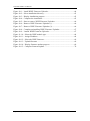
WISE (Web Inside, Smart Engine) is a product series developed by ICP DAS that
functions as control units for use in remote logic control and monitoring in various
industrial applications. WISE offers a user-friendly and intuitive HMI interface that
allows users to implement control logic on controllers just a few clicks away; no
programming is required. With this powerful and easy-to-use software, it will
minimize the learning curve, shorten time to market and dramatically reduce the labor
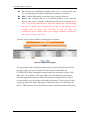
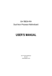
and cost spent on system development. WISE system architecture is shown as below:
Figure 1-1:WISE system architecture
Through Web browser, users can access Web Server on ICP DAS WISE controllers to
perform tasks such as logic edition and download. A Rule Engine will be set up to
manage and deploy rules for controllers. The Rule Engine will check whether the
rules are valid or not and determine the execution of actions under specific conditions,
for examples: setting up I/O channel values, perform scheduled tasks, sending Email
or sending SMS message under a specific condition. In addition, through the Modbus
TCP Protocol, it enables SCADA software to control and monitor I/O channel or
system status on controllers in real time.
http://wise.icpdas.com
7
ICP DAS WISE User Manual
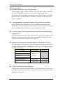
WISE system features:
IF-THEN-ELSE logic rules execution ability
WISE controller equips with an IF-THEN-ELSE logic Rule Engine, it offers up
to 36 IF-THEN-ELSE rules for users to set up the logic content. After
completing rule edition and downloading rules to the WISE controller, the Rule
Engine will loop execute the rules in accordance with the execute order under
specific conditions.
No programming is required to implement logic content on controllers
WISE provides user-friendly Web UI pages for editing control logic on the
controllers. It enables to implement logic edition by a few clicks on the mouse to
set up and deploy logic rules without writing a single line of code.
No extra software tool is required; all operations can be done through the
Web browsers
WISE HMI interface runs on regular Web browsers. To edit control logic, it only
requires a browser to connect to the Web server on WISE controller. No extra
software tool installation is needed on the target PC.
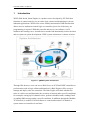
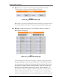
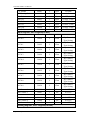
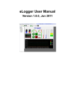
Support various hardware controllers that are with different I/O types
The wide range of I/O function modules ICP DAS provided allows users to find
best solutions that meet their requirements. Please refer to the following table for
modules and functions:
Functions
Without Display
With Display
Analog Input Modules
Multi Function I/O
WISE-71xx
Series
Digital I/O
Relay Output & Digital Input
I/O Expansion Boards
WISE-7901
WISE-7901D
SMS
WISE-4000
WISE-4000D
Figure 1-2:WISE Series Products
Provide Timer and Schedule operation
WISE features two kind of timing functions: Timer and Schedule. It allows user
to schedule specific date or time for control logic execution, or perform specific
tasks such as time delay.
http://wise.icpdas.com
8
ICP DAS WISE User Manual
Real-time remote alarm via SMS or Email and CGI command sending
functions
WISE supports SMS, Email and CGI command sending functions. SMS and
Email functions are important functions for real-time message communication.
The sending action can be added to the logic edition as part of logic control to
provide real-time message transmission function or sending CGI command for
device control in response to specific events.
Fully P2P function between WISE controllers
WISE offers P2P function that enables WISE controllers to directly communicate
with other remote WISE controllers on networks. All WISE controllers can
freely share their status information such as I/O channel value, DI/DO Counter
or Internal Register to each others. The P2P operations can be incorporated into
WISE logic rules as Condition statements or Action statements for Condition
evaluation criteria or Action executions.
Recipe function for Group Action operation
WISE provides Recipe function that allows to execute a sequence of actions
previously saved in the Recipe to response to IF-THEN-ELSE logic rules
Conditions. Different Recipe sets can be edited to meet various requirements for
different applications.
Real-time monitoring system status of controllers
WISE supports Modbus TCP Protocol for users to perform real-time monitoring
and control of the controllers. Please refer to Appendix 1 for the mapping table
of controller system information and Modbus TCP protocol Address. In addition,
WISE provides an easy-to-view HMI web interface for real-time monitoring. It
allows users to get important real time system information even without SCADA
software.
Password protection for access control when download logic rules
WISE HMI web page offers password protection; it allows users to modify the
password for access control when download the logic rules.
This document is intended to give you a full-range instruction to WISE-71xx
controllers. You will be able to learn how to edit logic of the rules and how to
download the rules to the controllers for conditional execution.
http://wise.icpdas.com
9
ICP DAS WISE User Manual
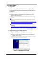
2 Before Connection
Before connecting to WISE Web HMI pages, please complete the following steps
for network configuration. The network configuration of the controllers has to be
set up for users to connect to Web server on WISE controllers.
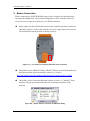
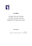
Please make sure the Init/Normal switch on the controller has been switched to
“Normal” position. Connect the controller to power supply and to the network.
The Init/Normal switch position is shown as below:
Figure 2-1:The switch is located at the back of the controller
Install and execute MiniOS7 Utility. MiniOS7 Utility can be downloaded from
the following link (please download version v321 or later):
http://ftp.icpdas.com/pub/cd/8000cd/napdos/minios7/utility/minios7_utility/
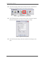
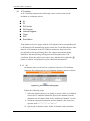
On toolbar, select ConnectionSearch (shown as below). A ”MiniOS7 Scan”
window will pop up and automatically start searching controllers in the
network.
Figure 2-2:Select “Search” function on MiniOS7 Utility
http://wise.icpdas.com
10
ICP DAS WISE User Manual
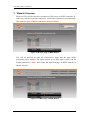
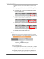
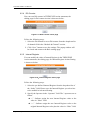
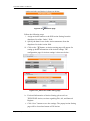
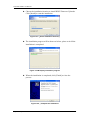
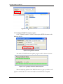
After finish searching, find the target controller and click "TCP Broadcast",
and then click "IP Setting" button on the toolbar as shown below:
Figure 2-3:IP Setting button on MiniOS7 Scan
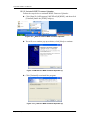
Click "IP Setting" button, a network settings window will pop up. Input the
information and click the "Set" button to complete the settings.
Figure 2-4:Network Settings page
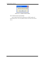
After finish Network settings, reboot the controller for the changes to take
effect.
http://wise.icpdas.com
11
ICP DAS WISE User Manual
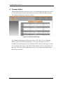
3 Website Overview
Please use IE or Firefox browser to connect to Web server on WISE controller. In
order to get a better operation experience, 1280x1024 resolution is recommended.
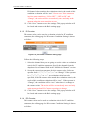
The main web page of WISE controller is shown as below:
Figure 3-1:Login page of WISE Web UI
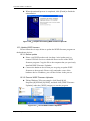
You will be required to enter the password to login into the page before
performing logic settings. The login section is on right upper corner, and the
default password is “wise”. After login, the main web page of WISE controller is
shown as below:
Figure 3-2:Main page of WISE Web UI
http://wise.icpdas.com
12
ICP DAS WISE User Manual
Six buttons will appear on the upper part of the Web page:
Basic Setting
Advanced Setting
Rules Setting
Channel Status
Upload from Module
Download to Module
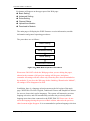
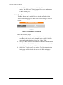
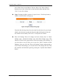
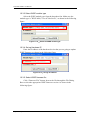
The main page will display the WISE firmware version information, module
information and general operating procedures.
The procedures are as follows:
Basic Setting
Advanced Setting
Rules Setting
Download to Module
Figure 3-3:WISE Web UI Operation Procedures
Please note: DO NOT refresh the Web page when you are editing the pages,
otherwise the contents of all previous settings will be gone. And please
remember all settings will take effect only when they have been downloaded to
the modules, if you close the Web page before finishing “Download to Module”,
all settings will be disappeared as well.
In addition, there is a language selection menu on the left region of the main
page. WISE Web UI offers: English, Traditional Chinese and Simplified Chinese
for users to choose their prefer languages. The system will memorize previous
language selection, and will automatically switch to the previously chosen
language next time when connected to the WISE Web UI. Please note: do not
select the language during the process of Rule edition; otherwise the previous
edited content might disappear. It is recommended to perform language selection
http://wise.icpdas.com
13
ICP DAS WISE User Manual
at the beginning when connected to the WISE Web UI or after finishing
“Download to Module”.
WISE-71xx equips v1.20(or later) firmware would upload the rule setting
automatically when the web page is connected.
More detail information of each button will be given in the following parts.
http://wise.icpdas.com
14
ICP DAS WISE User Manual
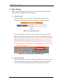
4 Basic Setting
Under the Basic Setting section, it allows to perform Name Setting, Ethernet
Setting, Module Setting and Password Setting.
4.1 Name Setting
Name Setting Page is for you to give your controller a name for easy
recognition and identification. Name Setting Page is shown as follow:
Figure 4-1:Name Setting page
If you have already given a name to this controller, when you get on this
page, the name you previously set up will be shown on the pane. After you
modify or input the name, click Save to save the name. The name you input
will appear on the top of the page as shown below. Please note: the Save
button on Name Setting Page is for temporary storage only, to complete the
Name Setting and save the change to the controller, please finish the process
of “Download to Module”.
Figure 4-2:The Name location in WISE Web Page
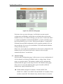
4.2 Ethernet Setting
Ethernet Setting allows you to set network configuration, web server port,
the NetID of Modbus TCP protocol and Modbus TCP port on hardware
devices. The following figure illustrates the configuration interface:
http://wise.icpdas.com
15
ICP DAS WISE User Manual
Figure 4-3:Ethernet setting page
Each time when you enter this page, it will display current network
configuration and Modbus settings that are automatically read from the
hardware devices. For Ethernet settings, you can select “Connection Mode”
as “Obtain an IP address automatically(DHCP)” to let the controller to get
the IP from DHCP server, or select “Specify an IP address” to modify the
IP/Mask/Gateway/DNS configuration of the controller manually. You can
also modify the web server port, the Modbus TCP NetID and the Modbus
TCP port in the same way.
Please note: if you make any modification to the network configuration, the
hardware device will reboot itself and re-connect to the web page
automatically about 5 seconds later.
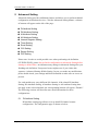
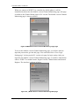
4.3 Module Setting
On the module configuration page, it allows users to set up configuration of
AI/AO channels on Analog I/O Module such as: voltage range, current
range, or operation modes. The hardware module will be automatically
detected and will appear on the drop down list. The Module Setting page
allows users to set up the following three types of module (different
modules may equip with different I/O):
DI/DO Module (Digital I/O module): includes WISE-7144,
WISE-7151, WISE-7152, WISE-7160 and WISE-7167 modules. These
modules contain DI / DO channels only, therefore there is no need to
http://wise.icpdas.com
16
ICP DAS WISE User Manual
set up configuration for channel operation. The setting page is shown
as below:
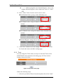
Figure 4-4:WISE-71xx DI/DO module setting page
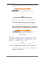
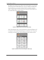
AI / DO Module (Analog Input module): includes WISE-7105,
WISE-7115, WISE-7117, WISE-7118Z and WISE-7119 modules.
These modules contains AI channel, therefore the voltage range,
current range, or operation mode (such as Thermistor, RTD or
Thermocouple) of each AI channel must be defined. If the AI channel
is connected with Sensor Input (Thermistor, RTD or Thermocouple),
WISE provide Celsius(℃) and Fahrenheit(℉) unit selection for the AI
input. The setting page is shown as below:
Figure 4-5:WISE-71xx AI/DO module setting page
AI / AO Module (Analog I/O module): WISE-7126 module. This
module equips with both AI and AO channel, therefore the voltage
range or current range for each AI /AO channel must be defined. The
setting page is shown as below:
http://wise.icpdas.com
17
ICP DAS WISE User Manual
Figure 4-6:WISE-71xx AI/AO module setting page
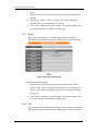
4.4 Password Setting
Password Setting allows users to change the password and password hint
for access control when download logic rules. The Password Setting page is
as follow:
Figure 4-7:Password setting page
To avoid unauthorized access and altering of data; it is required for users to
input password before they start to download control logic to the controllers.
The default password is set as “wise”. You can modify the password and
password hint on this page. Password length is limited to 16 characters and
the password hint length is limited to 20 characters.
http://wise.icpdas.com
18
ICP DAS WISE User Manual
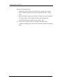
5 Advanced Setting
Advanced Setting provides additional features and allows you to perform channel
configuration on hardware devices. Click the Advanced Setting button, a column
of buttons will appear on the left of the page:
DI Attribute Setting
DO Attribute Setting
AI Attribute Setting
AO Attribute Setting
Internal Register Setting
Timer Setting
Email Setting
CGI Setting
Recipe Setting
P2P Setting
Please note: In order to avoid possible error when performing rule definition
(IF-THEN-ELSE), please always finish configuration in Advanced Setting before
starting to define Rules. Avoid unnecessary change in Advanced Setting after you
finishing rule definition. Unexpected errors might occur if you violate this
sequence: Advanced Setting Rule Setting. In case you make any modification,
please double check your settings and Rules definition to make sure no errors are
present.
For each module may carry different I/O channels, if the related DI Attribute
Setting, DO Attribute Setting, AI Attribute Setting or AO Attribute Setting does
not apply to the selected module, the corresponding buttons will appear “Disable”.
The following sections will describe more detail information for these
configurations.
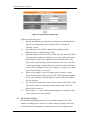
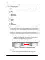
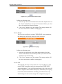
5.1 DI Attribute Setting
DI Attribute setting page allows to set up detail DI channel counter
configuration. The configuration page is shown as below:
http://wise.icpdas.com
19
ICP DAS WISE User Manual
Figure 5-1:DI Attribute setting page
Follow the following steps:
i. Specify the channel you are going to configure by selecting channel
index from the dropdown list of channel field in “Module &
ii.
iii.
iv.
v.
vi.
Channel” section.
Input Nickname for each I/O channel, this nickname will be
displayed on the “Channel Status” page.
Input the time interval in the “Filter” field. The time interval for filter
is the minimum duration a signal has to present to make a change to
the DI channel value. If the signal last shorter than this filter time
interval, this signal change will be determined to be noise instead of
a valid signal change. Default Filter time interval will be 0 and this
value must be multiples of 10ms, for example, a setting of 20 would
mean a 200 ms filter (20 x10 ms).
Please set the trigger criteria for triggering the counter to count.
There are three criteria: HI to LOW, LOW to HI and Status Change.
If you select “Disable” indicates that the counter of this DI channel
will not function.
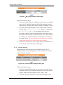
You can set the initial value of the counter in the “Initial Value” field.
This counter will start counting from the initial count value. The
default initial value is 0.
Repeat steps i ~ v. After all DI channel settings are completed, click
“Save” button to save the changes.
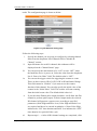
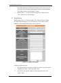
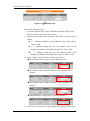
5.2 DO Attribute Setting
DO Attribute Setting page allows to set up detail configuration of DO
channel, including Power On value, Counter and Pulse Output. You don’t
need to finish all configurations; configure the one(s) according to your
http://wise.icpdas.com
20
ICP DAS WISE User Manual
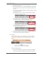
needs. The configuration page is shown as below:
Figure 5-2:DO Attribute setting page
Follow the following steps:
i. Specify the channel you are going to configure by selecting channel
index from the dropdown list of channel field in “Module &
ii.
iii.
iv.
v.
vi.
Channel” section.
Input Nickname for each I/O channel, this nickname will be
displayed on the “Channel Status” page.
You can specify the initial status to be “ON” or to be “OFF” when
the hardware device is power on. Select the value from the dropdown
list of “Power On Value” field. The default value is “OFF”.
You can set the trigger criteria for triggering the counter to count.
There are three criteria: HI to LOW, LOW to HI and Status Change.
This field cannot be “Disable” if you want to use the counter
function of this channel. You can also specify the initial value of the
counter in the “Initial Value” field. This counter will start counting
from the initial count value. The default initial value is 0.
If you check the Enable pulse output checkbox, it will allow this DO
channel to perform pulse output. In Pulse Output mode, the selected
DO channel will generate a square wave according to specified
parameters (Pulse High and Pulse Low). Pulse High and Pulse Low
are required and has to be entered in multiples of 10ms. Pulse High
indicates the “ON” time duration and Pulse Low indicates the “OFF”
time duration in a periodic Pulse cycle.
Repeat steps i ~ v. After all DO channel settings are completed, click
http://wise.icpdas.com
21
ICP DAS WISE User Manual
“Save” button to save the changes.
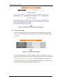
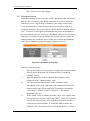
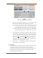
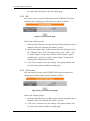
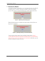
5.3 AI Attribute Setting
AI Attribute Setting section is for specifying a Deadband value and a scale
range for the AI channel on the WISE controller. As we know, when the
controller receives a signal from AI channel, if the change of this value
received matches the evaluation criteria that was previously defined in
Condition statements; the result of this IF-THEN-ELSE evaluation will be
“true”. In order to avoid signal oscillation that may result in instability to
the status changes, the user can set up a Deadband value for the AI channel;
when there is a change to the AI channel, the actions will occur when this
change matches the evaluation criteria value plus or minus the Deadband
value. The AI attribute configuration page is shown as below:
Figure 5-3:AI attribute setting page
Follow the following steps:
i.
Specify the channel you are going to configure by selecting channel
index from the dropdown list of channel field in “Module &
Channel” section.
ii.
Input Nickname for each I/O channel, this nickname will be
displayed on the “Channel Status” page.
iii.
iv.
You can set the Deadband value of this AI channel in the
“Deadband” field, on the right side of the Deadband field, the AI
channel value range will be displayed. Forexample, the channel
value range is -500mV~500mV in Figure 5-3. The default
Deadband value is 0.
In the “Scale” field, AI channel raw data can be set to operate with
linear proportion between “MIN” and “MAX” values. IF Condition
will use the adjusted value in the logic Rule operation, and the AI
value retrieved from Modbus TCP and Web HMI would be the
adjusted value. The default value for MAX and MIN is 0, it mean
http://wise.icpdas.com
22
ICP DAS WISE User Manual
v.
disable the Scale function.
Repeat steps i ~ iv. After all AI Channel settings are completed,
click “Save” button to save the changes.
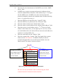
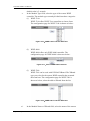
There are three operation styles for AI Deadband. Detail description is as
below. The AI Channel setting in following examples is 0mA ~ 20mA.
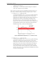
(1) When AI > or >= a numerical value :
Assuming the Deadband value is set to be 2 mA, and the following
statements are defined in the related logic Rule: IF AI0>10mA,
THEN DO=ON, ELSE DO=OFF, that means, when AI0 receives a
signal that exceed 10mA, the DO channel will change to ON
immediately, however, when the AI0 channel value drops and
becomes lower than 10mA, the DO channel will not change back to
OFF immediately until the value reaches 8mA (10mA minus the
Deadband value 2mA), as shown in following figure.
Figure 5-4:AI Deadband Operation(> or >= a numerical value)
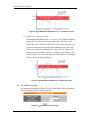
(2) When AI < or <= a numerical value :
Assuming the Deadband value is set to be 2 mA, and the following
statements are defined in the related logic Rule: IF AI0<10mA,
THEN DO=ON, ELSE DO=OFF, that means, when AI0 receives a
signal which is lower than 10mA, the DO channel will change to
ON immediately, however, when the AI0 channel value exceed
10mA, the DO channel will not change back to OFF immediately
until the value reaches 12mA (10mA plus the Deadband value 2mA),
as shown in following figure.
http://wise.icpdas.com
23
ICP DAS WISE User Manual
Figure 5-5:AI Deadband Operation(< or <= a numerical value)
(3) When AI = a numerical value :
Assuming the Deadband value is set to be 1 mA, and the following
statements are defined in the related logic Rule: IF AI0 = 9mA,
THEN DO=ON, ELSE DO=OFF, that means, when AI0 receives a
signal between 8mA (9mA minus the deadband value 1mA) and
10mA (9mA plus the deadband value 1mA), the DO channel will
change to ON immediately. However, when the AI0 channel value
exceed 10mA, or is lower than 8mA, the DO channel will change to
OFF, as shown in following figure.
Figure 5-6:AI Deadband Operation(= a numerical value)
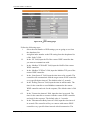
5.4 AO Attribute Setting
AO Attribute Setting page allows to set up initial value of the AO channel.
The configuration page is shown as below:
Figure 5-7:AO Attribute setting page
http://wise.icpdas.com
24
ICP DAS WISE User Manual
Follow the following steps:
i. Specify the channel you are going to configure by selecting channel
index from the dropdown list of channel field in “Module &
Channel” section.
ii. Input Nickname for each I/O channel, this nickname will be
displayed on the “Channel Status” page.
iii. You can set the initial value of the AO channel in the “Power On
Value” field. The hardware device will output this value when is
iv.
power on. The default initial value is 0.
Repeat steps i ~ iii. After all AO Channel settings are completed,
click “Save” button to save the changes.
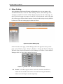
5.5 Internal Register Setting
WISE provides 48 Internal Registers; they can be used to hold temporary
variables and to read/write data via Modbus address. The configuration
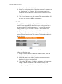
page is shown as below:
Figure 5-8:Internal Register setting page
Follow the following steps:
http://wise.icpdas.com
25
ICP DAS WISE User Manual
i.
ii.
A checkbox appears in front of each Internal Register; check the
checkbox to enable the Internal Register, or check the checkbox in
the “Enable” field to enable all Internal Register in the same row also.
Input a value if you want to set a default value for that Internal
Register, and set the nicknames for the Internal Register, this
nickname will be displayed on the “Channel Status” page.
After you finish all Internal Registers selections and settings, click
“Save” button to save the settings.
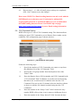
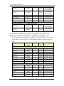
5.6 Timer Setting
WISE provides 12 groups Timer for timing functions. The Timer status can
be “Not Timeout” or “Timeout”. They can be included in the IF Condition
statements. The Timer Action can be “Start” or “Reset”. The Start Action
will start to run the Timer and if the Start Action is triggered one more time
when the Timer is running, the Timer will restart again. The Reset action
will reset the Timer and stop running the Timer. The Timer will be in
“Timeout” status only when the Timer is running and reached the setting
time, otherwise, the status of Timer will remain in “Not Timeout”. The
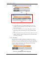
Timer setting interface is shown as below:
Figure 5-9:Timer setting page
Follow the following steps:
i. “Timer Amount” field is required. Select the total number of timer
you are going to use from the dropdown list.
ii. Specify the timer you want to set up by selecting its index number
from the dropdown list of the “Index” field.
iii. “Period” field is required for each timer; please input the period
interval in units of seconds.
iv. Specify the initial status of each timer from the dropdown list of the
“Initial Status” field. Select “Start” indicates the timer will start to
count as soon as the hardware device is power up. “Stop” indicates
http://wise.icpdas.com
26
ICP DAS WISE User Manual
v.
the Timer will remain off when the hardware device is power up; it
will not be activated until being triggered under certain conditions.
The default setting of initial Status is “Stop”.
Repeat steps ii ~ iv. After all timer settings are completed, click
“Save” button to save the changes.
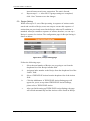
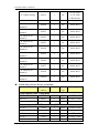
5.7 Email Setting
WISE supports up to 12 Email messages. This function allows sending
pre-input Email message(s) to pre-set Email receiver(s) under certain
conditions. The configuration page is shown as below:
Figure 5-10:Email setting page
Follow the following steps:
i. Specify the numbers of email messages you want to set up from the
dropdown list of the “E-mail Amount” field.
ii. Specify the email group number from the dropdown list of the
“Index” field.
http://wise.icpdas.com
27
ICP DAS WISE User Manual
iii.
iv.
v.
vi.
vii.
viii.
ix.
x.
xi.
Enter the IP or the domain name of the SMTP server in the “SMTP
Server” field.
If SMTP server requires account and password validation, please
select the Authentication Checkbox, and continue steps v~vi to login
into the SMTP server. If SMTP server don’t need account and
password validation, uncheck the Authentication Checkbox and skip
steps v~vi, go directly to step vii.
Enter the SMTP server login ID in the “Login ID” field.
Enter the SMTP server password in the “Password” field.
Enter the sender’s name in the “Sender Name” field.
Enter the sender’s email address in the “Sender Email Address” field.
Enter the receiver’s email address in the “1st ~5th Receiver Email
address” field. Please note: you can input up to 5 receivers, at least
one email address has to be entered. Please enter the email address in
sequence to avoid possible error.
Enter the email subject in the “Subject” field.
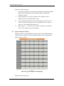
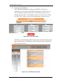
Enter the content in the “Content” field. The length of the content
cannot exceed 160 characters. In addition, Email provides an
encoded string that allow user to add current channel value into
Email content. The syntax is shown as below:
$aiN
Variables are prefixed
The variable type:
The channel index.
with a dollar sign $ to
ai
AI channel value
Please note: Do not
get the value of the
ao
AO channel value
input the un-existed
current channel.
di
DI channel value
channel index.
do
DO channel value
ci
DI counter value
co
DO counter value
ir
Internal Register
Figure 5-11:Email channel value encoded syntax
The user can also add channel value encoded string into Email
content from the I/O channel selection interface.
http://wise.icpdas.com
28
ICP DAS WISE User Manual
xii.
Repeat steps ii ~ xi. After all email groups settings are completed,
click “Save” button to save the changes.
Please note: WISE-71xx Email sending function can only work with the
SMTP Email server that uses port 25 and must be without SSL
cryptographic protocols. A self-hosted SMTP server is recommended
for Email sending function. Please visit WISE FAQ web page
(http://wise.icpdas.com/FAQ.html) for more Email setting information.
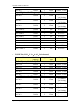
5.8 CGI Command Setting
WISE offers up to 12 sets of CGI Command setting. This function allows
sending pre-input CGI Command to pre-set Remote Server under certain
conditions. The configuration page is shown as below:
Figure 5-12:CGI Command setting page
Follow the following steps:
i.
Specify the numbers of CGI Commands you want to set up from
the dropdown list of the “CGI Amount” field.
ii.
Specify the CGI group number from the dropdown list of the
iii.
iv.
v.
“Index” field.
Enter the Remote Server IP, Port number and CGI Command in the
“CGI Command” field. In addition, it provides an encoded string
that allow user to add current I/O channel value into the CGI
Command. You can use the I/O channel selection interface (shown
as above) to add the I/O channel encoded string into the CGI
Command.
Enter the number in the “Retry Count” field. It means the retry
number WISE will try when it can’t connect with Remote Server.
Enter the number in the “Retry Interval” field. It means the time
http://wise.icpdas.com
29
ICP DAS WISE User Manual
vi.
interval between each retry connection. The unit is Second
Repeat steps ii ~ v. After all CGI groups settings are completed,
click “Save” button to save the changes
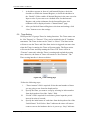
5.9 Recipe Setting
WISE offers up to 12 sets of Recipe setting. A sequence of actions can be
stored and saved in a Recipe, users can setup to execute this sequence of
actions that was previously stored in the Recipe when an IF condition is
matched. A Recipe contains a sequence of actions, therefore, we can say a
Recipe is a macro for Actions. The configuration page for Recipe Setting is
shown as below:
Figure 5-13:Recipe setting page
Follow the following steps:
i.
Select the total number of Recipe you are going to use from the
dropdown list of the Recipe Amount field.
ii.
Assign an index number to the Recipe from the dropdown list of the
“Index” field.
iii.
Select a THEN/ELSE Action from the dropdown list of the Action
field.
iv.
Click the Add button. A THEN/ELSE Action Setting page will
v.
appear for you to set up related THEN/ELSE Action Settings,
please refer to THEN/ELSE Action.
After you finish setting up THEN/ELSE Action Settings, the page
will refresh automatically and the Actions will be listed on Recipe.
http://wise.icpdas.com
30
ICP DAS WISE User Manual
Figure 5-14:Recipe Action management
In order to meet application requirement, for some Actions, WISE
offers options to execute the Action one-time or repeatedly.
One Time:When the IF Condition is TRUE, this Action will
be executed once and only once. This Action will not be
executed again until the IF Condition turns to be TRUE again.
Repeat:When the IF Condition is TRUE, this Action will be
executed repeatedly until the IF Condition turns to be FALSE.
vi.
All selected Actions will be listed on the Recipe page. Click on the
radio checkbox to select the target Action, you can edit the selected
Action by click on Edit button, or delete the Action from the list by
click on Delete button. To rearrange the order of the Action, click
the Move Up
or Move Down
button to move the target
Action to the desired order. To delete all Actions, click on the Clear
vii.
All button to remove all actions from the list.
Repeat steps ii ~ vi. After all Recipe settings are completed, click
“Save” button to save the changes.
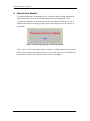
5.10 P2P Setting
WISE supports up to 8 P2P Setting. This function enables WISE controllers
to communicate with other remote controllers directly. The remote
controllers can freely share their data such as I/O value, DI/DO Counter or
Internal Register status information with local WISE controller. The
configuration page is shown as below:
http://wise.icpdas.com
31
ICP DAS WISE User Manual
Figure 5-15:P2P setting page
Follow the following steps:
i.
Select the total number of P2P settings you are going to use from
the dropdown list.
ii.
Assign an index number to the P2P setting from the dropdown list
iii.
iv.
v.
vi.
vii.
viii.
ix.
of the “Index” field.
In the “IP” field, input the IP of the remote WISE controller that
you want to communicate with.
In the “Modbus TCP NetID” field, input the NetID of the remote
WISE controller.
In the “Modbus TCP Port” field, input the Modsbu TCP port of the
remote WISE controller.
In the “Scan Interval” field, input the time interval in seconds. The
controller will communicate with the target remote WISE controller
every specified time-interval. The default value is 5 seconds.
In the "Polling Timeout" field, input the time in milliseconds. The
time for the controller to send Modbus command to the remote
WISE controller and wait for the response, The default value is 500
ms.
In the "Connection timeout" field, input the time in seconds. The
time for the controller to connect with the remote WISE controller
and wait for the response, The default value is 3 seconds.
In the "Disconnection Retry Interval" field, input the time interval
in seconds. The controller will try to connect with remote WISE
controller every specified time-interval after disconnection. The
http://wise.icpdas.com
32
ICP DAS WISE User Manual
x.
default value is 5 seconds.
In the Module Type field, select the type of the remote WISE
controller. The module type currently divided into three categories:
(1) WISE-7100:
WISE-7100 offers WISE-71xx controllers to choose from.
The configuration page for WISE-7100 is shown as below:
Figure 5-16:WISE-7100 Controller Selection
(2) WISE-4000
WISE-4000 offers only WISE-4000 controller. The
configuration page for WISE-4000 is shown as below:
Figure 5-17:Select WISE-4000 Controller
(3) WISE-7901:
WISE-7901 can be used with ICP DAS XBoard. The XBoard
type you select for the remote WISE controller has to match
the actual one. The configuration page for WISE-7901 is
shown as below, select the add-on Xboard from the list:
Figure 5-18:WISE-7901 Controller Selection
xi.
In the Module Name or XBoard field, select the name of the remote
http://wise.icpdas.com
33
ICP DAS WISE User Manual
xii.
WISE controller from the dropdown list.
Repeat steps ii ~ xi. After all P2P settings are completed, click
“Save” button to save the changes.
http://wise.icpdas.com
34
ICP DAS WISE User Manual
6 Rules Setting
After finishing all Advanced Setting configurations, the user can start to edit
IF-THEN-ELSE rules. Click the “Rules Setting” button, a Rule Manager table
will appear, and the list of rules will be displayed on the left side of the page. At
the left side of the page, the status of each rule will be displayed. And at the right
side of the page will show detail content of each rule that was previously defined
by the users. The rule setting page is shown as below:
Figure 6-1:Rules Setting page
On the left side of the page, a Rule Manager table will appear at the top of the
page. It provides the “Copy”, “Reset”, “Reorder”, “Swap” and “Reset all Setting”
functions. More detail information for Rule Manager will follow. Under the Rule
Manager table, the list of rule contains four items:
Figure 6-2:Enable rules, edit rules and status display
Enable: A checkbox appears before each rule; check the checkbox to
enable the rule and this rule will be executed after being downloaded,
otherwise it will only be stored temporarily.
http://wise.icpdas.com
35
ICP DAS WISE User Manual
No.: Indicates the identification number of the rule. To avoid possible error,
it is recommended to assign the identification number in sequence.
Edit: Click the Edit button to edit detail logic content of the rule.
Status: “OK” indicates this rule is successfully defined. “Error” indicates
there is error occurs. “Disable” indicates this rule not be executed. Please
note: if you make modification in Advanced Setting after finish defining
the rules, it might cause unexpected error due to the changes, some
variables may no longer exist. Therefore, in case you make any
modification, please double check your settings and Rules definition to
make sure no errors are present.
Click the “Edit” button, the Rules Setting page will appear:
Figure 6-3:Rule Setting page
The rule number will be displayed at the top of the page. The Description field
provides a space for users to make a brief description of this Rule. An
IF-THEN-ELSE Rule setting table appears under the description section. Each
Rule offer 3 IF conditions. The user could create IF(condition) statements by
selecting appropriate operator (AND, OR) from the dropdown list. In order to
avoid possible errors, the design of this table is foolproof: The user has to finish
setting up Condition1 before moving on Condition2, and so on. Each Rule also
offers 3 THEN actions, and 3 ELSE actions. More detail information will follow.
http://wise.icpdas.com
36
ICP DAS WISE User Manual
6.1 IF Condition
In IF Condition statement, the following values or their status can be
included as evaluation criteria:
AI
DI
DI Counter
DO Counter
Internal Register
Timer
P2P
Rule Status
If the hardware device equips with AI or DI channel, their corresponding AI
or DI channel will automatically appear on the list. To include subjects other
than AI or DI channels in the IF Condition statement; they have to be
pre-defined in Advanced Setting first. The subjects that already being
defined in Advanced Setting will appear on the dropdown list of IF
Condition. Select the subject you want to use, and then click right side
button, a window will pop up for you to edit detail information.
6.1.1 AI
AI channel value can be used as evaluation criteria for IF condition
statement; the editing page for AI Condition Setting is shown as below:
Figure 6-4:AI condition setting page
Follow the following steps:
i. Select the channel that you are going to use the value as evaluation
criteria for IF condition statement. Specify the channel from the
dropdown list of channel field in the “Module & Channel” section.
ii. Set up the expression statement for this channel value. Select an
operator from “=”,”>”,”<”,”>=” or “<=”.
iii. Specify the evaluation value. If this AI channel value match the
http://wise.icpdas.com
37
ICP DAS WISE User Manual
evaluation criteria, the result of this condition evaluation will be
“true”.
You can compare the AI channel value with the following 3 values
for condition evaluation:
Self-Defined value:Giving a self-defined value to compare
with the AI channel value.
AI Channel value:Using other AI channel values from the local
module to compare with the AI channel value.
Internal Register:Using the internal register value to compare
with the AI channel value.
iv. Click “Save” button to save the settings. The popup window will
be closed and return to the Rule settings page.
6.1.2 DI
DI channel value can be used as evaluation criteria for IF condition
statement; the editing page for DI Condition Setting is shown as below:
Figure 6-5:DI condition setting page
Follow the following steps:
i. Select the channel that you are going to use the value as evaluation
criteria for IF condition statement. Specify the channel from the
dropdown list of channel field in “Module & Channel” section.
ii. Define the evaluation criteria of the status in IF statement to be
“OFF” “ON” “ON to OFF” “OFF to ON” or “Change”. Once the
http://wise.icpdas.com
38
ICP DAS WISE User Manual
DI channel value matches the evaluation criteria, the result of this
condition evaluation will be “true”. Please note: If the statement
involves state transitions: “ON to OFF”, “OFF to ON” and
“Change”, the action will be executed only once and only at the
moment when the state transition occurs.
iii. Click “Save” button to save the settings. This popup window will
be closed and return to the Rule settings page.
6.1.3 DI Counter
DI counter value can be used as evaluation criteria for IF condition
statement; the editing page for DI counter Condition Setting is shown
as follow:
Figure 6-6:DI counter condition setting page
Follow the following steps:
i. Select the channel that you are going to use the value as evaluation
criteria for IF condition statement. Specify the channel from the
dropdown list of channel field in the “Module & Channel” section.
ii. Set up the expression statement for this counter value. Select an
operator from “=”,”>”,”<”,”>=”,“<=” or “Change”. If the operator
is “=”,”>”,”<”,”>=” or “<=”, an evaluation value has to be
specified; if the DI counter value match the evaluation criteria, the
result of this condition evaluation will be “true”. If the operator is
“Change”, the condition will be “true” when there is a change to
the counter value. The action will be executed only once and only
at the moment when DO Counter experience a change.
iii. Click “Save” button to save the settings. This popup window will
be closed and return to the Rule settings page.
6.1.4 DO Counter
DO counter value can be used as evaluation criteria for IF condition
statement; the editing page for DO counter Condition Setting is shown
as follow:
http://wise.icpdas.com
39
ICP DAS WISE User Manual
Figure 6-7:DO counter condition setting page
Follow the following steps:
i. Select the channel that you are going to use the value as evaluation
criteria for IF condition statement. Specify the channel from the
dropdown list of channel field in the “Module & Channel” section.
ii. Set up the expression statement for this counter value. Select an
operator from “=”,”>”,”<”,”>=”,“<=” or “change”. If the operator
is “=”,”>”,”<”,”>=” or “<=”, an evaluation value has to be
specified; if this DO counter value match the evaluation criteria,
the result of this condition evaluation will be “true”. If the operator
is “Change”, the condition will be true when there is a change to
the counter value. The action will be executed only once and only
at the moment when DO Counter experience a change.
iii. Click “Save” button to save the settings. This popup window will
be closed and return to the Rule settings page.
6.1.5 Internal Register
Internal Register value can be used as evaluation criteria for IF
condition statement; the editing page for Internal Register Condition
Setting is shown as follow:
Figure 6-8:Internal register condition setting page
Follow the following steps:
i. Select the Internal Register that you are going to use the value as
evaluation criteria for IF condition statement. Specify the Internal
Register Index from the dropdown list of “Index” field.
ii. Set up the expression statement for this Internal Register value.
http://wise.icpdas.com
40
ICP DAS WISE User Manual
Select an operator from “=”,”>”,”<”,”>=” or “<=”.
iii. Specify the evaluation value. If this Internal Register value match
the evaluation criteria, the result of this condition evaluation will
be “true”.
You can compare the Internal Register with the following 3 values
for condition evaluation:
Self-Defined value:Giving a self-defined value to compare
with the Internal Register value.
AI Channel value:Using AI channel values from the local
module to compare with the Internal Register value.
Internal Register:Using other internal register value to compare
with the Internal Register value.
iv. Click “Save” button to save the settings. The popup window will
be closed and return to the Rule settings page.
6.1.6 Timer
Timer condition can be used as evaluation criteria for IF condition
statement; the editing page for timer condition setting is shown as
follow:
Figure 6-9:Timer condition setting page
Follow the following steps:
i. Select the timer that you are going to use its status as evaluation
criteria for IF condition statement. Specify the timer index from
http://wise.icpdas.com
41
ICP DAS WISE User Manual
the dropdown list of “Index” field.
ii. Define the evaluation criteria of the timer status in IF statement to
be “Not timeout” or “Timeout”. If the timer status match the
evaluation criteria, the result of this condition evaluation will be
“true”.
iii. Click “Save” button to save the settings. The popup window will
be closed and return to the Rule settings page.
6.1.7 P2P
Through P2P function, the data (DI, AI, DI/DO Counter or Internal
Register) from remote WISE controllers can be retrieved and can be
incorporated into IF Condition statements. To set up P2P condition
Setting, first of all, you will need to assign an index number and
specify what data you are going to use in the IF condition statements.
Secondly, you will need to set up detail settings for the Condition
settings. The configuration page for setting up index and condition is
shown as below:
Figure 6-10:P2P IF Condition setting page
Follow the following steps:
i. Assign an index number to the P2P Condition Setting from the
dropdown list of the “Index” field.
ii. Specify the data for use in the Condition statements from the
dropdown list in the Condition field.
iii. Click on the
button, a Condition setting page will appear for
setting up detail information of the Condition settings. The
configuration page for Condition settings is shown as below:
http://wise.icpdas.com
42
ICP DAS WISE User Manual
Figure 6-11:P2P IF Condition detail setting page
iv. For detail information of Condition Setting, please refer to IF
Condition; sections regarding DI, AI, DI Counter, DO Counter,
and Internal Register.
v. Click “Save” button to save the settings. The popup Condition
Setting page will be closed and return to P2P Condition setting
page.
vi. On the P2P Condition setting page, click “Save” button to save the
settings. The P2P Condition setting page will be closed and return
to the Rule Setting page.
6.1.8 Rule Status
The Rule Status (if the Rule is disabled or enabled) can be used as
evaluation criteria for IF condition statement. Please note: there must
be at least one edited rule on WISE controller for setting up Rule Status
in the IF Condition Setting page. The editing page for Rule Status
Condition Setting is shown as below:
Figure 6-12:Rule Status IF Condition setting page
http://wise.icpdas.com
43
ICP DAS WISE User Manual
Follow the following steps:
i. Specify the index number of the Rule that is going to be used in
the IF Condition statement from the dropdown list of the “Index”
field.
ii. Specify the Rule status to be Disable or Enable from the dropdown
list of the “Status” field. When the Rule status matches the
specified status, the evaluation result will be “true”.
iii. Click “Save” button to save the settings. The Rule Status
Condition Setting page will be closed and return to the Rule setting
page.
http://wise.icpdas.com
44
ICP DAS WISE User Manual
6.2 THEN/ELSE Action
In the THEN/ELSE Action statement, the following values or status can be
included:
AO
DO
DI Counter
DO Counter
Internal Register
Timer
Email
CGI
Recipe
P2P
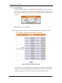
Rule Status
Select the component for Action statement from the combo box, and then
click the right side
button, a window will pop up for you to edit detail
information. The THEN Action statement will be executed only when the
result of IF condition statement is found “true”; otherwise the ELSE Action
statement will be executed. In order to meet application requirement, for
some Actions, WISE offers options to execute the Action one-time or
repeatedly.
One Time: when the IF Condition is TRUE, this Action will be
executed once and only once. This Action will not be executed
again until the IF Condition turns to be TRUE again.
Repeat: when the IF Condition is TRUE, this Action will be
executed repeatedly until the IF Condition turns to be FALSE.
Figure 6-13:”One-Time Action” & ”Repeat Action” Items
6.2.1 AO
You can execute an action in AO channel in THEN/ELSE Action
statement; the editing page for AO Action is shown as follow:
http://wise.icpdas.com
45
ICP DAS WISE User Manual
Figure 6-14:AO action page
Follow the following steps:
i. From the dropdown list of the “Module & Channel” field, select
the AO channel index to execute actions.
ii. Specify the Operator in the “Operator” field. The 3 operators are as
follow:
“=”:Indicate assign the new AO channel value as the value in
“Value” field.
“+=”:Indicate assign the new AO channel value as the
original AO channel value plus the value in “Value” field.
“-=”:Indicate assign the new AO channel value as the
original AO channel value minus the value in “Value” field.
iii. In the “Value” field, 4 sources can be used as value:
Self-Defined Value: giving a value defined by user
AI Channel value: using AI channel values from the local
module
AO Channel value: using AO channel values from the local
module
Internal Register: using value of Internal Register
iv. Click “Save” button to save the settings. The popup window will
http://wise.icpdas.com
46
ICP DAS WISE User Manual
be closed and will return to the rule setting page.
6.2.2 DO
You can execute an action in DO channel in the THEN/ELSE Action
statement; the editing page for DO Action is shown as follow:
Figure 6-15:DO action page
Follow the following steps:
i. Select the DO channel to execute actions from the dropdown list of
channel field in the “Module & Channel” section.
ii. Specify the output value of DO Channel from the dropdown list of
the “Channel Value” field. The output value can be “OFF”, “ON”
or “Pulse Output”. Please note: to make “Pulse Output” option
available here, you have to enable “Pulse Output” in Advanced
Setting before editing Rules Setting.
iii. Click “Save” button to save the settings. The popup window will
be closed and return to the Rule settings page.
6.2.3 DI Counter
You can reset DI counter in the THEN/ELSE Action statement; the
editing page for DI counter Action is shown as follow:
Figure 6-16:DI counter action page
Follow the following steps:
i. Select the DI channel to reset DI counter from the dropdown list of
channel field in the “Module & Channel” section.
ii. Click “Save” button to save the settings. The popup window will
be closed and return to the Rule settings page.
http://wise.icpdas.com
47
ICP DAS WISE User Manual
6.2.4 DO Counter
You can reset DO counter in THEN/ELSE Action statement; the
editing page for DO counter Action is shown as below:
Figure 6-17:DO counter action page
Follow the following steps:
i. Select the DO channel to reset DO counter from the dropdown list
of channel field in the “Module & Channel” section.
ii. Click “Save” button to save the settings. The popup window will
be closed and return to the Rule settings page.
6.2.5 Internal Register
You can modify the value of Internal Register in the THEN/ELSE
Action statement; the editing page for Internal Register Action Setting
is shown as below:
Figure 6-18:Internal Register action page
Follow the following steps:
i. Select the pre-defined Internal Register from the dropdown list of
the “Index” field. Please note: the Internal Register you select has
to be enabled in Advanced Setting.
ii. Specify the Operator in the “Operator” field. The 3 operators are as
follow:
“=”:Indicate assign the new Internal Register value as the
value in “Value” field.
“+=”:Indicate assign the new Internal Register value as the
original Internal Register value plus the value in “Value” field.
http://wise.icpdas.com
48
ICP DAS WISE User Manual
“-=”:Indicate assign the new Internal Register value as the
original Internal Register value minus the value in “Value”
field.
iii. In the “Value” field, 4 sources can be used as value:
Self-Defined Value: giving a value defined by user
AI Channel value: using AI channel values from the local
module
AO Channel value: using AO channel values from the local
module
Internal Register: using value of Internal Register
iv. Click “Save” button to save the settings. The popup window will
be closed and return to the Rule settings page.
6.2.6 Timer
You can change the Timer status (to stop or to start the Timer) in the
THEN/ELSE Action statement; the editing page for Timer Action
Setting is shown as below:
Figure 6-19:Timer action page
Follow the following steps:
i. Select the pre-defined Timer from the dropdown list of the “Index”
http://wise.icpdas.com
49
ICP DAS WISE User Manual
field.
ii. Please note: the Timer you select has to be enabled in Advanced
Setting.
iii. Specify you want to “Reset” or “Start” this Timer when this
THEN/ELSE Action statement is executed.
iv. Click “Save” button to save the settings. The popup window will
be closed and return to the Rule settings page.
6.2.7 Email
You can send a message to an Email group when executing a
THEN/ELSE Action statement; the editing page is shown as below:
Figure 6-20:Email action page
Follow the following steps:
i. Select the pre-set Email group from the dropdown list of the
“Index” field. The Email group information will be displayed for
you to verify if this is the Email group you are going to send the
message to.
ii. Click “Save” button to save the settings. The popup window will
be closed and return to the Rule settings page.
6.2.8 CGI
You can send a CGI Command to a Remote Server when executing a
THEN/ELSE Action statement; the editing page is shown as below:
http://wise.icpdas.com
50
ICP DAS WISE User Manual
Figure 6-21:CGI Command action page
Follow the following steps:
i. Select the pre-set CGI Command action from the dropdown list of
the “Index” field. Please note: the CGI Command Index you select
has to be enabled in Advanced Setting.
ii. Click “Save” button to save the settings. The popup window will
be closed and return to the Rule settings page.
6.2.9 Recipe
You can execute a Recipe action in THEN/ELSE Action statement;
the editing page for Recipe Action is shown as follow:
Figure 6-22:Recipe action page
Follow the following steps:
i. Select the pre-set Recipe action from the dropdown list of the
“Index” field. Please note: the Recipe Index you select has to be
enabled in Advanced Setting.
ii. Click “Save” button to save the settings. The popup window will
be closed and return to the Rule settings page.
6.2.10 P2P
Through P2P function, the data (DO,AO or Internal Register) from
remote WISE controllers can be incorporated into THEN/ELSE
Action statements. To set up P2P Action Setting, first of all, you will
need to assign an index number and specify what data you are going
to use in the Action statements. Secondly, you will need to set up
detail settings for the Action settings. The configuration page for
http://wise.icpdas.com
51
ICP DAS WISE User Manual
setting up index and Action is shown as below:
Figure 6-23:P2P action page
Follow the following steps:
i. Assign an index number to the P2P Action Setting from the
dropdown list of the “Index” field.
ii. Specify the data for use in the Action statements from the
dropdown list in the Action field.
iii. Click on the
button, an Action setting page will appear for
setting up detail information of the Action settings. The
configuration page for Action settings is shown as below:
Figure 6-24:P2P action detail setting page
iv. For detail information of Action Setting, please refer to
THEN/ELSE Action; sections regarding DO, AO, and Internal
Register.
v. Click “Save” button to save the settings. The popup Action Setting
page will be closed and return to P2P Action
http://wise.icpdas.com
52
ICP DAS WISE User Manual
vi. On the P2P Action setting page, click “Save” button to save the
settings. The P2P Action setting page will be closed and return to
the Rule Setting page.
6.2.11 Rule Status
The Rule Status can be modified to be Disable or Enable in the
Action. The editing page for Rule Status Action Setting is shown as
below:
Figure 6-25:Rule Status action page
Follow the following steps:
i. Specify the index number of the Rule (It has to be a previously
saved Rule) that is going to be changed in the Action Condition
statement from the dropdown list of the “Index” field.
ii. Specify the Rule status to be Disable or Enable from the dropdown
list of the “Status” field. When the Action being executed, the Rule
status will be changed to specified status.
iii. Click “Save” button to save the settings. The Rule Status Action
Setting page will be closed and return to the Rule setting page.
http://wise.icpdas.com
53
ICP DAS WISE User Manual
6.3 Summary of the Rules
After you finish editing all IF condition and THEN / ELSE action
statements for a rule, return to the Rules Setting page and click “Save” to
save all settings of this rule. Please note: if you want to clear previous
settings, after you click “Clear” button, you have to click “Save” to make
sure this “Clear” status is saved. Rules Setting page is shown as below:
Figure 6-26:Clear/Save Rules
Each time you finish editing a Rule will go back to the Rules Setting main
page. All statements of edited Rules will be displayed. Rules Setting main
page is shown as below:
Figure 6-27:Rule Setting main page
http://wise.icpdas.com
54
ICP DAS WISE User Manual
Click “Rules Setting” button to display detail rules description. Rules can be
downloaded to the hardware device immediately after you successfully set
up one or more rule(s).
http://wise.icpdas.com
55
ICP DAS WISE User Manual
6.4 Rule Manager
The Rule Manager allows easy modification and deployment with existing
rules. By a few simple steps, users can easily change the rule orders or make
modification with previously edited rules. The Rule Manager table is shown
as below:
Figure 6-28:Rule Manager setting page
Rule Manager offers 5 functions:
Copy: Copy the content of previously edited rule to another rule. Click
“Copy” button, a window as shown below will pop up:
Figure 6-29:Rule Copy setting page
Select the source rule from the first field, and then select the destination(s)
from the second fields (multiple rule destinations is allowed). Click “Save”
button to copy the content of the source rule to all destination rules.
http://wise.icpdas.com
56
ICP DAS WISE User Manual
Reset: allows to clear rule content of previously edited rules. Click
“Reset” button, a window as shown below will pop up:
Figure 6-30:Rule Reset setting page
Rules that are previously edited will be listed on the page, select the rule to
be cleared and then click “Save” button, the rule you select will be reset.
Reorder: reorder existing rules. Click “Reorder” button, a window as
shown below will pop up:
Figure 6-31:Rule Reorder setting page
A menu will appear at the top of the page, it contains a drop down list for
selecting the target rule, and a pair of “Move Up”/“Move Down” buttons
to move target rule to the desired location. All rule locations will be listed
in sequence (currently support 36 rule locations). If the rule content of a
specific rule location has been previously edited, “Rule Content X” (X :
rule sequence index) will appear. If the rule content of the rule location is
blank, it will be specified as “None”. To reorder a rule, select the target
rule from the dropdown list, the corresponding “Rule content X” font will
http://wise.icpdas.com
57
ICP DAS WISE User Manual
turn to blue from its usual black. Click on “Move Up”/“Move Down”
buttons to move the selected rule to the desired location and then click
“Save” to save the settings.
Swap: Exchange the Rule content of a pair of rules. Click Swap button, a
window as shown below will pop up:
Figure 6-32:Rule Swap setting page
From the left side drop down list, select the first rule (has to be previously
edited), and select the second rule from the right side drop down list (the
rule content can be blank), click “Save” to swap the rule content.
Reset All Settings: Reset all settings and rules already done in “Basic
Setting” page, “Advanced Setting” page and “Rule Setting” page. This
function is used for the requirement to restart all setting of the controller. If
you just want to reset all rules, you can use the “Reset” function in Rule
Manager. After you click the “Reset All Settings” button inadvertently to
reset all rules and settings, you can still retrieve all settings and rules from
the controller and edit them again by pressing the “Upload from Module”
button.
http://wise.icpdas.com
58
ICP DAS WISE User Manual
7 Download to Module
“Download to Module” button allows you to download edited rules from Web UI
to hardware devices. Click the "Download to Module" button, the download
process will be started. Current download progress will be displayed as below:
Figure 7-1:Showing download progress
When the download process is finished, the popup window will notify the user
the process is completed:
Figure 7-2:Message showing a successful download
Close the popup window and go back to the Rules Setting window. About 3
seconds after the download is completed, the hardware device will automatically
reboot and start to run the rules that have been downloaded. At this time, you can
still edit or modify the content of the rules.
http://wise.icpdas.com
59
ICP DAS WISE User Manual
8 Upload from Module
“Upload from Module” button allows you to retrieve Rules Setting information
from the hardware devices and edit them at this Rules Setting page. Click
“Upload from Module” to start the upload process. When the upload process is
finished, the window showing progress status will notify the user the process is
completed:
Figure 8-1:Message showing a successful upload
Click “close” to close the upload process window to finish upload. Now the rules
have been uploaded from hardware devices to the web page, you can modify and
download the edited rules to the hardware devices later again.
http://wise.icpdas.com
60
ICP DAS WISE User Manual
9 Channel Status
Channel Status function offers an easy-to-view monitoring page that allows users
to view important controller information in real time without SCADA software.
The Channel Status page is shown as below:
Figure 9-1:Channel Status page
The Channel Status page will show the values of DI / DO / AI / AO channel,
DI/DO counter, and the Internal Register. If you give nicknames to the I/O
channels or Internal Registers, the nicknames will be shown on this page as well.
You can modify the values of the DO/AO/IR channels with the value buttons on
this page. This page will be updated once every 10 seconds, showing the latest
data of the controllers.
http://wise.icpdas.com
61
ICP DAS WISE User Manual
When you connect to WISE-71xx controller by mobile phone, it will be
automatically directed to the Mobile version Channel Monitoring page; this page
is similar to the Channel Status page for PC version. The Mobile version Channel
Monitoring page is shown as below:
Figure 9-2:Mobile Version Channel Monitoring Login page
To access the Mobile version Channel Monitoring page, you will be asked to
input the password to get into this page. You could also select “Go to Logic
Setting page” to bring up the PC version web page for logic setting. After you
login into the Mobile version Channel Monitoring page, it will show information
such as: WISE-71xx module name, Engine Version, Channel Status and Internal
Register. The interface is shown as below:
Figure 9-3:Mobile Version Channel Monitoring Main page
http://wise.icpdas.com
62
ICP DAS WISE User Manual
The DI/DO/AI/AO channel value, DI/DO counter and Nickname of each channel
will be shown on the Channel Status page. To set up or modify out channel data
of specific DO/AO, you can click on specific DO/AO to modify or input the
values of output channel. Click the top title bar to go back to the main page. The
I/O Channel Status page is shown as below:
Figure 9-4:Mobile Version I/O Channel Status page
On the Internal Register page, values and nicknames of all Internal Registers will
be displayed. Click on specific Internal Register to modify the value. To go back
to main page, click the title bar. The Internal Register page is shown as below:
Figure 9-5:Mobile Version Internal Register Status page
http://wise.icpdas.com
63
ICP DAS WISE User Manual
10 Firmware Update
10.1 Introduction
WISE Firmware Uploader is a software tool provides a user friendly
interface to easily update WISE firmware that runs on WISE hardware
devices. With a few clicks, users could upload the latest WISE firmware to
the hardware.
System Requirements:
Operating System: Windows Server 2003, Windows Server 2008,
Windows Vista, Windows XP.
Make sure you have installed Microsoft .NET Framework Version 2.0
(or later)
You can download Microsoft .Net Framework Version 2.0 from the
link below:
http://www.microsoft.com/downloads/details.aspx?FamilyID=0
856eacb-4362-4b0d-8edd-aab15c5e04f5&DisplayLang=en
You can download Microsoft .Net Framework Version 3.5 from the
link below:
http://www.microsoft.com/downloads/details.aspx?familyid=3
33325FD-AE52-4E35-B531-508D977D32A6&displaylang=en
10.2 Install / Uninstall WISE Firmware Uploader
10.2.1 Install WISE Firmware Uploader
Follow the steps below to install WISE Firmware Uploader:
Obtain the WISE Firmware Uploader setup file (WISE Firmware
Uploader Setup V2.0.exe).
Double click the setup file to install the file, you will see a window
pop up as below, click [Next] to continue.
Figure 10-1:Install WISE Firmware Uploader
http://wise.icpdas.com
64
ICP DAS WISE User Manual
Choose the installation location to install WISE Firmware Uploader.
Click [Install] to start the installation.
Figure 10-2:Select installation directory
The installation progress will be shown as below; please wait till the
installation is completed.
Figure 10-3:Display installation progress
When the installation is completed, click [Finish] to close the
process.
Figure 10-4:Complete the installation
http://wise.icpdas.com
65
ICP DAS WISE User Manual
10.2.2 Uninstall WISE Firmware Uploader
Follow the steps below to uninstall WISE Firmware Uploader:
Click [Start] [All Programs][ICPDAS][WISE], and then click
[Uninstall] under the [WISE] category.
Figure 10-5:Start to remove WISE Firmware Uploader
You will see a window pop up as below, click [Next] to continue.
Figure 10-6:Remove WISE Firmware Uploader (1)
Click [Uninstall] to uninstall the program.
Figure 10-7:Remove WISE Firmware Uploader (2)
http://wise.icpdas.com
66
ICP DAS WISE User Manual
When the uninstall process is completed, click [Finish] to finish the
uninstallation.
Figure 10-8:Complete uninstalling WISE Firmware Uploader
10.3 Update WISE firmware
Please follow the six steps below to update the WISE firmware program on
the hardware devices:
10.3.1 Before update
Please visit WISE product web site (http://wise.icpdas.com/) or
contact ICP DAS service to obtain the latest version of the WISE
firmware program. Copy the file to the computer that you previously
installed WISE Firmware Uploader.
Connect the hardware device that you are going to update WISE
firmware to the network. Please verify and make a note of the
hardware device IP address, you will need it later in the process.
10.3.2 Execute WISE Firmware Uploader
Taking Windows XP as an example: click [Start][All
Programs][ICPDAS][WISE], and then click [WISE Firmware
Uploader] under the [WISE] category to start the program.
Figure 10-9:Launch WISE Firmware Uploader
http://wise.icpdas.com
67
ICP DAS WISE User Manual
10.3.3 Select WISE module type
Select the WISE module type from the dropdown list. Make sure the
module type is ”WISE 4000, 71xx & 790x Series”, as shown in the following
figure.
Figure 11-10:Select the WISE module type
10.3.4 Set up Hardware IP
Enter the IP address of the hardware device that you are going to update
WISE firmware, as shown in the following figure.
Figure 10-11:Assign IP address
10.3.5 Select WISE firmware file
Click “Firmware File” button; browse the file through the File Dialog
Box to select the appropriate WISE firmware version. As shown in the
following figure:
http://wise.icpdas.com
68
ICP DAS WISE User Manual
Figure 10-12:Select the WISE firmware
10.3.6 Upload WISE firmware program
Click ”Upload Firmware” button to start update WISE firmware to the
hardware device.
Figure 10-13:Upload firmware
The status of WISE firmware update progress will be shown as below:
Figure 10-14:Display firmware update progress
When completing update of the WISE firmware, a pop-up window will
appear to inform the user. Close the window to finish firmware upload.
http://wise.icpdas.com
69
ICP DAS WISE User Manual
Figure 10-15:Complete firmware update
10.3.7 Module reboot automatically
After complete the firmware update process, WISE module will
automatically reboot. The new updated firmware will take effect after the
reboot.
http://wise.icpdas.com
70
ICP DAS WISE User Manual
Appendix I:Modbus Address Table
WISE allows you to retrieve data on hardware devices via Modbus TCP.
Please Note :
The addresses are in Base 0 format
The addresses are listed in Decimal format
The default value of NetID is 1, and you can modify the NetID value in the
Ethernet Setting page. (Please refer to 4.2 Ethernet Setting).
The default value of Port is 502, and you can modify the Port value in the
Ethernet Setting page. (Please refer to 4.2 Ethernet Setting).
If the data is displayed in Floating format (AI channel value, AO channel
value or Internal Register, etc.), each record of data will take two registers to
hold the data. The following code example demonstrates how to join the two
registers into one floating point value.
float register_to_float(short r1, short r2)
{
float f;
int *a = &f;
*a = r1;
a++;
*a = r2;
return f;
}
Please note: for the compilers are different (big endian or little endian), the
floating point composing order might be different. For example: if r1 represent
the address of 30040 register and r2 represent the address of 30041 register, to
join r1 and r2 to a floating point, in the system is big endian system you will need
to call:
float value = register_to_float(r1, r2);
Instead, if the system is little endian system, you will need to call:
float value = register_to_float(r2, r1);
PS: if you are not sure your editor belongs to which system, try both systems to
find the accurate one.
http://wise.icpdas.com
71
ICP DAS WISE User Manual
1. System Data
The following table lists the Modbus address of WISE-71xx system information:
Parameter Name
Modbus
Address
Length
Data
Type
Range
1
Byte
1=reboot
Coils Output, Unit : Coil(8 Bits)
Reboot switch
00000
Input Register, Unit : Register(16 Bits)
Module Name
30000
1
Int
0~65535
Firmware Version
30002
2
Float
Floating Point
Alive Counter
30004
1
Int
0~65535
Cycle Time
30005
1
Int
0~65535
MAC Address 1
30006
1
Int
0~255
MAC Address 2
30007
1
Int
0~255
MAC Address 3
30008
1
Int
0~255
MAC Address 4
30009
1
Int
0~255
MAC Address 5
30010
1
Int
0~255
MAC Address 6
30011
1
Int
0~255
Web Port
30012
1
Int
1~65535
Modbus TCP NetID
30013
1
Int
1~255
Modbus TCP Port
30014
1
Int
1~65535
Holding Register, Unit : Register(16 Bits)
Ethernet IP 1
40000
1
Int
0~255
Ethernet IP 2
40001
1
Int
0~255
Ethernet IP 3
40002
1
Int
0~255
Ethernet IP 4
40003
1
Int
0~255
Subnet Mask 1
40004
1
Int
0~255
Subnet Mask 2
40005
1
Int
0~255
Subnet Mask 3
40006
1
Int
0~255
Subnet Mask 4
40007
1
Int
0~255
Gateway 1
40008
1
Int
0~255
Gateway 2
40009
1
Int
0~255
Gateway 3
40010
1
Int
0~255
Gateway 4
40011
1
Int
0~255
http://wise.icpdas.com
72
ICP DAS WISE User Manual
2. Channel Data
The following lists all Modbus address tables of WISE-71xx modules I/O channel
data.
WISE-7105、WISE-7117 (4 DO、8 AI channel) or WISE-7115 (7 AI channel)
Parameter Name
Modbus
Address
Length
Data
Type
Range
Coils Outputs, Unit : Coil(8 Bits)
DO Ch.0
00020
1
Byte
0=OFF, 1=ON
DO Ch.1
00021
1
Byte
0=OFF, 1=ON
DO Ch.2
00022
1
Byte
0=OFF, 1=ON
DO Ch.3
00023
1
Byte
0=OFF, 1=ON
Input Register, Unit :Register(16 Bits)
By Channel
AI Ch.0
30020
2
Float
AI Ch.1
30022
2
Float
AI Ch.2
30024
2
Float
AI Ch.3
30026
2
Float
By Channel
Type Setting
AI Ch.4
30028
2
Float
By Channel
Type Setting
AI Ch.5
30030
2
Float
By Channel
Type Setting
AI Ch.6
30032
2
Float
By Channel
Type Setting
AI Ch.7
30034
2
Float
By Channel
Type Setting
DO Counter 0
30080
1
Int
0~65535
DO Counter 1
30081
1
Int
0~65535
DO Counter 2
30082
1
Int
0~65535
DO Counter 3
30083
1
Int
0~65535
Type Setting
By Channel
Type Setting
By Channel
Type Setting
WISE-7118Z (6 DO、10 AI channel) or WISE-7119 (4 DO、8 AI channel)
Parameter Name
Modbus
Address
Length
Data
Range
Type
Coils Outputs, Unit : Coil(8 Bits)
http://wise.icpdas.com
73
ICP DAS WISE User Manual
CJC Enable
00001
1
Byte
1=Enable
CJC Setting Switch
00002
1
Byte
1=Set
DO Ch.0
00020
1
Byte
0=OFF, 1=ON
DO Ch.1
00021
1
Byte
0=OFF, 1=ON
DO Ch.2
00022
1
Byte
0=OFF, 1=ON
DO Ch.3
00023
1
Byte
0=OFF, 1=ON
DO Ch.4
00024
1
Byte
0=OFF, 1=ON
DO Ch.5
00025
1
Byte
0=OFF, 1=ON
Input Register, Unit :Register(16 Bits)
CJC Value
30014
1
Int
-32768~32767
AI Ch.0
30020
2
Float
By Channel
Type Setting
AI Ch.1
30022
2
Float
By Channel
Type Setting
AI Ch.2
30024
2
Float
By Channel
Type Setting
AI Ch.3
30026
2
Float
By Channel
Type Setting
AI Ch.4
30028
2
Float
By Channel
Type Setting
AI Ch.5
30030
2
Float
By Channel
Type Setting
AI Ch.6
30032
2
Float
By Channel
Type Setting
AI Ch.7
30034
2
Float
By Channel
Type Setting
AI Ch.8
30036
2
Float
AI Ch.9
30038
2
Float
By Channel
Type Setting
DO Counter 0
30080
1
Int
0~65535
DO Counter 1
30081
1
Int
0~65535
DO Counter 2
30082
1
Int
0~65535
DO Counter 3
30083
1
Int
0~65535
DO Counter 4
30084
1
Int
0~65535
DO Counter 5
30085
1
Int
0~65535
By Channel
Type Setting
Holding Register, Unit : Register(16 Bits)
http://wise.icpdas.com
74
ICP DAS WISE User Manual
CJC Update Setting
40012
1
Int
0=CJC Stop
1=CJC Start
2=Read Once
CJC Total Offset
40013
1
Int
-4096~4095
CJC offset of AI
channel 0
40020
1
Int
-4096~4095
CJC offset of AI
channel 1
40021
1
Int
-4096~4095
40022
1
Int
-4096~4095
CJC offset of AI
channel 3
40023
1
Int
-4096~4095
CJC offset of AI
channel 4
40024
1
Int
-4096~4095
CJC offset of AI
channel 5
40025
1
Int
-4096~4095
CJC offset of AI
channel 6
40026
1
Int
-4096~4095
CJC offset of AI
channel 7
40027
1
Int
-4096~4095
CJC offset of AI
channel 8
40028
1
Int
-4096~4095
CJC offset of AI
channel 9
40029
1
Int
-4096~4095
Length
Data
Range
CJC offset of AI
channel 2
WISE-7102 (6 DI、3 DO、3 AI channel)
Parameter Name
Modbus
Address
Type
Coils Outputs, Unit : Coil(8 Bits)
DO Ch.0
00020
1
Byte
0=OFF, 1=ON
DO Ch.1
00021
1
Byte
0=OFF, 1=ON
DO Ch.2
00022
1
Byte
0=OFF, 1=ON
Discrete Inputs, Unit : Discrete Input (8 Bits)
DI Ch.0
10020
1
Byte
0=OFF, 1=ON
DI Ch.1
10021
1
Byte
0=OFF, 1=ON
DI Ch.2
10022
1
Byte
0=OFF, 1=ON
DI Ch.3
10023
1
Byte
0=OFF, 1=ON
DI Ch.4
10024
1
Byte
0=OFF, 1=ON
http://wise.icpdas.com
75
ICP DAS WISE User Manual
DI Ch.5
10025
1
Byte
0=OFF, 1=ON
Input Register, Unit :Register(16 Bits)
AI Ch.0
30020
2
Float
By Channel
Type Setting
AI Ch.1
30022
2
Float
By Channel
Type Setting
AI Ch.2
30024
2
Float
By Channel
Type Setting
DI Counter 0
30060
1
Int
0~65535
DI Counter 1
30061
1
Int
0~65535
DI Counter 2
30062
1
Int
0~65535
DI Counter 3
30063
1
Int
0~65535
DI Counter 4
30064
1
Int
0~65535
DI Counter 5
30065
1
Int
0~65535
DO Counter 0
30080
1
Int
0~65535
DO Counter 1
30081
1
Int
0~65535
DO Counter 2
30082
1
Int
0~65535
Length
Data
Type
Range
WISE-7126 (2 DI、2 DO、6 AI、2 AO channel)
Parameter Name
Modbus
Address
Coils Outputs, Unit : Coil(8 Bits)
DO Ch.0
00020
1
Byte
0=OFF, 1=ON
DO Ch.1
00021
1
Byte
0=OFF, 1=ON
Discrete Inputs, Unit : Discrete Input (8 Bits)
DI Ch.0
10020
1
Byte
0=OFF, 1=ON
DI Ch.1
10021
1
Byte
0=OFF, 1=ON
Input Register, Unit :Register(16 Bits)
AI Ch.0
30020
2
Float
By Channel
Type Setting
AI Ch.1
30022
2
Float
By Channel
Type Setting
AI Ch.2
30024
2
Float
By Channel
Type Setting
AI Ch.3
30026
2
Float
http://wise.icpdas.com
By Channel
Type Setting
76
ICP DAS WISE User Manual
AI Ch.4
30028
2
Float
By Channel
Type Setting
AI Ch.5
30030
2
Float
By Channel
Type Setting
DI Counter 0
30060
1
Int
0~65535
DI Counter 1
30061
1
Int
0~65535
DO Counter 0
30080
1
Int
0~65535
DO Counter 1
30081
1
Int
0~65535
Holding Register, Unit : Register(16 Bits)
AO Ch.0
40020
2
Float
By Channel
Type Setting
AO Ch.1
40022
2
Float
By Channel
Type Setting
WISE-7142、WISE-7144、WISE-7151、WISE-7152、WISE-7153、
WISE-7160、WISE-7167 (Maximum 16 DI channel and 8 DO channel)
According to the channel numbers of WISE-71xx DI/DO Module, you can look
up the address of the WISE-71xx DI/DO Module channel from the following
table:
Parameter Name
Modbus
Address
Length
Data
Type
Range
Coils Outputs, Unit : Coil(8 Bits)
DO Ch.0
00020
1
Byte
0=OFF, 1=ON
DO Ch.1
00021
1
Byte
0=OFF, 1=ON
DO Ch.2
00022
1
Byte
0=OFF, 1=ON
DO Ch.3
00023
1
Byte
0=OFF, 1=ON
DO Ch.4
00024
1
Byte
0=OFF, 1=ON
DO Ch.5
00025
1
Byte
0=OFF, 1=ON
DO Ch.6
00026
1
Byte
0=OFF, 1=ON
DO Ch.7
00027
1
Byte
0=OFF, 1=ON
Discrete Inputs, Unit : Discrete Input (8 Bits)
DI Ch.0
10020
1
Byte
0=OFF, 1=ON
DI Ch.1
10021
1
Byte
0=OFF, 1=ON
DI Ch.2
10022
1
Byte
0=OFF, 1=ON
DI Ch.3
10023
1
Byte
0=OFF, 1=ON
DI Ch.4
10024
1
Byte
0=OFF, 1=ON
DI Ch.5
10025
1
Byte
0=OFF, 1=ON
http://wise.icpdas.com
77
ICP DAS WISE User Manual
DI Ch.6
10026
1
Byte
0=OFF, 1=ON
DI Ch.7
10027
1
Byte
0=OFF, 1=ON
DI Ch.8
10028
1
Byte
0=OFF, 1=ON
DI Ch.9
10029
1
Byte
0=OFF, 1=ON
DI Ch.10
10030
1
Byte
0=OFF, 1=ON
DI Ch.11
10031
1
Byte
0=OFF, 1=ON
DI Ch.12
10032
1
Byte
0=OFF, 1=ON
DI Ch.13
10033
1
Byte
0=OFF, 1=ON
DI Ch.14
10034
1
Byte
0=OFF, 1=ON
DI Ch.15
10035
1
Byte
0=OFF, 1=ON
Input Register, Unit :Register(16 Bits)
DI Counter 0
30060
1
Int
0~65535
DI Counter 1
30061
1
Int
0~65535
DI Counter 2
30062
1
Int
0~65535
DI Counter 3
30063
1
Int
0~65535
DI Counter 4
30064
1
Int
0~65535
DI Counter 5
30065
1
Int
0~65535
DI Counter 6
30066
1
Int
0~65535
DI Counter 7
30067
1
Int
0~65535
DI Counter 8
30068
1
Int
0~65535
DI Counter 9
30069
1
Int
0~65535
DI Counter 10
30070
1
Int
0~65535
DI Counter 11
30071
1
Int
0~65535
DI Counter 12
30072
1
Int
0~65535
DI Counter 13
30073
1
Int
0~65535
DI Counter 14
30074
1
Int
0~65535
DI Counter 15
30075
1
Int
0~65535
DO Counter 0
30080
1
Int
0~65535
DO Counter 1
30081
1
Int
0~65535
DO Counter 2
30082
1
Int
0~65535
DO Counter 3
30083
1
Int
0~65535
DO Counter 4
30084
1
Int
0~65535
DO Counter 5
30085
1
Int
0~65535
DO Counter 6
30086
1
Int
0~65535
DO Counter 7
30087
1
Int
0~65535
http://wise.icpdas.com
78
ICP DAS WISE User Manual
3. Internal Register Data
This table stores 48 sets of Internal Register data provided by WISE controller.
Parameter Name
Modbus
Address
Length
Data
Type
Range
Holding Register, Unit : Register(16 Bits)
Internal Register 01
40040
2
Float
Floating Point
Internal Register 02
40042
2
Float
Floating Point
Internal Register 03
40044
2
Float
Floating Point
Internal Register 04
40046
2
Float
Floating Point
Internal Register 05
40048
2
Float
Floating Point
Internal Register 06
40050
2
Float
Floating Point
Internal Register 07
40052
2
Float
Floating Point
Internal Register 08
40054
2
Float
Floating Point
Internal Register 09
40056
2
Float
Floating Point
Internal Register 10
40058
2
Float
Floating Point
………………………………………………………………..
Internal Register 45
40128
2
Float
Floating Point
Internal Register 46
40130
2
Float
Floating Point
Internal Register 47
40132
2
Float
Floating Point
Internal Register 48
40134
2
Float
Floating Point
http://wise.icpdas.com
79
ICP DAS WISE User Manual
Appendix II:Quick Start of CJC Settings for WISE-7118/
WISE-7119
7
1
2
3
4
5
6
1. Enter the Module Setting page of Basic Setting.
2. Check the CJC Enable checkbox.
3. You can set the total offset value of CJC in the “CJC Total Offset” field. Please
notice that the offset unit is 0.01°C or 0.018°F.
4. Select the CJC Update setting to “CJC Start”.
5. Also, you can set the CJC offset for each channel if the channel type was
thermocouple.
6. Press the Save button to save the settings.
7. Download the rules and the channel settings to the WISE module.
8. You can check the CJC value on the Channel Status page.
http://wise.icpdas.com
80
ICP DAS WISE User Manual
8
http://wise.icpdas.com
81