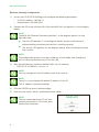
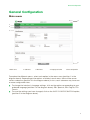
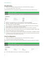
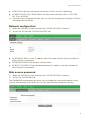
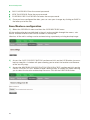
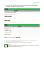
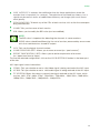
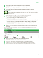
1
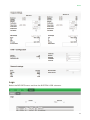
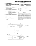
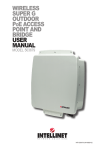
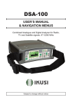
Web interface user guide
MHD-201
REF. 3854
High-definition modulator
Index
4
Introduction
4
About this Manual
4
Product Description
5
Web interface connection
5
Ethernet configuration by application IKUSI HEADEND DISCOVERY
6
Ethernet manually configuration
7
General Configuration
7
Main Menu
8
Identification
8
Local configuration
9
Network configuration
10
LCD+Joystick
10
Web access password
11
Save/Restore configuration
12
Upgrade
12
Restart
14
Signals Adjustment
14
Services
14
Input settings
15
Output settings
16
DVB-T Output
17
Network settings
18
USB player
19
Status
19
Input
19
Output
20
General
21
Reports
22
Settings
23
Logs
Introduction
Introduction
About this Manual
This manual describes the configuration environment of the MHD-201 modulator based on
web interface via Ethernet connection.
The Manual covers all configuration options: from start-up and operation, to adjusting the
settings and troubleshooting for the MHD-201.
The description consist of the connection procedure and access to the configuration settings, description of the environment and its contents, configuration options and interpretation of the information on the screen.
notE
This configuration manual is a practical reference guide. For the correct use and
installation of the MHD-201, it is essential to read the corresponding user manual
(please see www.ikusi.tv for the manual).
Product Description
The MHD-201 is a standalone modulator that can process different Video and Audio formats, to create a high-definition COFDM channel.
This product offers a solution to video signal distribution requirements in residential installations, hotels, special buildings or security video monitoring installations with COFDM digital
TV modulation. Likewise, the MHD-201 comes with a USB Interface which can incorporate
new functions thanks to the equipment’s evolvable software, such as: video playback from
USB for digital signage and other possible future functions
Features
The unit has various inputs:
• Two analogue audio and video channels, through 6 RCA connectors.
• One digital video and audio channel in HDMI format, through an HDMI connector.
• One digital video and audio channel in HD-SDI format, through a BNC connector.
Possible input combinations:
• SD CVBS/Audio + SD CVBS/Audio
2 simultaneous SD channels
• SD HDMI + SD CVBS/Audio
1 channel SD + USB
• SD SDI + SD CVBS/Audio
• SD + USB
• HD HDMI
• HD SDI
• HD + USB
1 channel HD
1 channel HD + USB
Output: Digital DVB-T TV signal over an RF carrier in VHF/UHF and IP signal.
Means of configuration:
• Web interface via Ethernet Connection (necessary for IP output configuration)
• SPI-300 Programming unit
4
Web Interface Connection
Web Interface Connection
ES
Ethernet Connection
The web user interface can be used to configure all the MHD-201 unit’s settings, using an
Ethernet connection and a web browser.
NOTE
To view the graphics provided in the unit’s configuration programme correctly,
we recommend installing Mozilla Firefox 1.5 or later (www.mozilla.com) on the
controlling PC.
Use a PC with an Ethernet network card and a CAT-5E Ethernet cable.
HDMI
V/A 1
V/A 2
VIDEO
VIDEO
AUDIO L
AUDIO L
AUDIO R
AUDIO R
MHD-201
Ref. 3854
DIGITAL MODULATOR
CONTROL
SYNC
STATUS
+12V
KEY
SDI
USB
1
LAN
Link
Act
2
3
1 - Ethernet Connector (LAN port, RJ-45)
2 - Link LED
DVB-T OUT
3 - Activity LED
Ethernet configuration by application:
si
H
ea
d e n d Di
ov
Ik u
ery
Download the IKUSI HEADEND DISCOVERY application available on the
website (www.ikusi.tv/en/headends/modulators/mac-series/MHD-201). In the
window we will find the model, the MAC number, serial number and manufacturing firmware version to access the interface of this module simply click on the
SET button. In the home page the USERNAME AND PASSWORD fields appear, enter
“admin” in both, click on the ENTER button.
sc
MHD-201
5
Web Interface Connection
Ethernet manually configuration:
1) Access the PC’S TCP/IP Settings and configure the following parameters:
FF
* PC’S /IP Address: 192.168.1.1
FF
* Subnet Mask: 255.255.255.0
2) Connect the PC to the LAN port (RJ-45) of the MHD-201 unit (position 1 in the diagram
below).
NOTE
The MHD-201 Ethernet Connector (position 1 in the diagram above), has two
light indicators:
JJ
The link LED (position 2 in the diagram above), remains continuously lit
without blinking to indicate that the link is working correctly.
JJ
The activity LED (position 3 in the diagram above), blinks to indicate that the
link is active.
NOTE
The configuration process must be carried out in local mode, even though the
unit can be accessed from any PC on the LAN.
3) Start the web browser and enter the MHD-201 unit’s IP address:
FF
Initial IP Address: 192.168.1.6
NOTE
You may change this initial IP address later if you wish to.
NOTE
The unit is also assigned the default IP address 10.0.0.22
This IP address cannot be modified.
4) Click on ENTER to access the home page.
5) Enter the user name “admin” and the password “admin”.
notE
The unit connected to the PC will automatically disconnect if 15 minutes pass
without any interaction.
.
6
MHD-201
General Configuration
General Configuration
ES
Main menu
4
1
2
3
5
1-Main menu
2-Submenus
3-Work area
4-Language selection
5-Save configuration
To explore the different menus, select each option in the menus area (position 1 in the
diagram above). Depending on the options available in each menu, there will be one or
various submenus (position 2 in the diagram above). In turn, each submenu may have one
or more configuration tabs.
JJ
JJ
To change the interface’s language settings, click on the option corresponding to your
preferred language (position 4 in the diagram above): ES= Spanish; EN= English; FR=
French.
To save the settings you have changed, click on the SAVE CONFIGURATION option,
(position 5 in the diagram above).
7
General Configuration
Identification
1) Select the GENERAL menu and then the CONFIGURATION submenu.
2) Access the IDENTIFICATION menu.
The IDENTIFICATION tab provides configuration data identifying the MHD-201 unit.
JJ
JJ
JJ
model: The name of the unit. This information cannot be modified.
serial number: Displays the manufacturers’ serial number identifying the unit.
This information cannot be modified.
MAC address: Automatically displays the MAC address of the unit for connection
to the network. This information cannot be modified.
JJ
IDENTIFIer: Identifying name assigned to the unit by the installer or operator.
JJ
LOCAtion: Name of the location where the unit is installed (for example: a post code).
JJ
installer: Name of the installer or operator.
JJ
CONTACT: Contact details of the installer or operator (for example: a telephone number).
3) Once you have finished configuring the data, you can save the changes by clicking on
the SAVE button on the lower part of the tab.
Local configuration
1) Select the GENERAL menu and then the CONFIGURATION submenu.
2) Access the local configuration tab.
This section is used to set the date, time and standard time zone of the MHD-201 modulator.
JJ
8
COUNTRY: Select the country in which the unit is operating.
General Configuration
JJ
JJ
TIME ZONE: Set the time zone of the country in which the unit is operating.
ES
CURRENT DATE AND TIME: Shows the hour, date and format (Date: yyyy-MMDD; Time: HH:MM).
3) Once you have configured the data, you can save the changes by clicking on SAVE on
the bottom part of the tab.
Network configuration
1) Select the GENERAL menu and then the CONFIGURATION submenu.
2) Access the network configuration tab.
JJ
JJ
JJ
IP address: Enter a static IP address within the range valid for the local network to
which the unit is connected.
network mask: Enter the local network mask.
DEFAULT GATEWAY: Enter the default gateway IP address in the local network to
which the unit is connected.
Web access password
1) Select the GENERAL menu and then the CONFIGURATION submenu.
2) Access the PASSWORD tab.
The PASSWORD configuration tab allows you to change the current password for accessing the web interface of the MHD-201 unit (see web interface connection section).
9
General Configuration
JJ
OLD PASSWORD: Enter the current password.
JJ
new PASSWORD: Enter the new password.
JJ
CONFIRM NEW PASSWORD: Re-enter the new password.
3) Once you have configured the data, you can save your changes by clicking on SAVE in
the lower part of the tab.
Save/Restore configuration
1) Select the GENERAL menu and then the SAVE/RESTORE menu.
All the configuration data established in the unit and accessible through the menus, submenus and web interface tabs can be stored in a backup file.
Likewise, all the unit’s settings can be restored using a previously existing backup image.
2) Access the SAVE CONFIGURATION section and click on the SAVE button to save a
backup copy file. A window will open allowing you to select the location and filename
of the security copy.
3) Access the RESTORE CONFIGURATION FROM BACKUP section and click on the
SELECT BACKUP COPY button to load a backup copy. A window will open allowing
you to select the location and backup file name. Click on the RESTORE button.
10
General Configuration
4) Access the RESTORE FACTORY SETTINGS tab and click on the FACTORY RESET button to reset the unit’s factory settings.
ES
Updgrade
Select the GENERAL menu and then the UPDATE submenu. The unit will automatically
display the currently installed firmware version.
JJ
JJ
SELECT THE UPDATE PACKAGE by clicking on the FILE SELECT button, to
select the firmware update file used by the unit.
To execute and load the new firmware click on the UPDATE button.
NOTE
The firmware update file has to be stored on the PC’s hard drive (it can be downloaded from http://www.ikusi.com).
11
General Configuration
Resart
1) Select the GENERAL menu and then the RESTART submenu.
2) Click on the RESTART button.
The RESTART configuration file can now be used to restart the MHD-201 unit.
3) Once you have restarted the unit, the home page will appear again.
MHD-201
12
Settings
Settings
ES
Services
Select the SETTINGS menu and then the SERVICES submenu. Specify the parameters
inside the SELECTION submenu:
JJ
INPUT TYPE: Specify one of the five possible combinations.
JJ
output type: DVB-T and IP
Specify the parameters within the INPUT SETTINGS submenu:
JJ
INPUT ASPECT RATIO: 16/9 or 4/3
The INPUT 1 tab reports on the status of the analogue AV TV input connected to the AV1
input, allowing you to modify how the audio and video components are processed.
To configure the AV2 input, select the INPUT 2 tab. The information, configuration options
and meanings are identical to those stated for INPUT 1.
13
Settings
Within the OUTPUT SETTINGS submenu, specify the following parameters:
JJ
JJ
JJ
JJ
JJ
JJ
JJ
JJ
14
BRIGHTNESS (1-255): Allows you to set the image’s brightness within a 1 to 255
range of values. You can enter a value or raise or lower the value unit-by-unit using the
buttons on the right of the value field.
CONTRAST (1-255): ): Allows you to set the image’s contrast within a 1 to 255 range of
values. You can enter a value or raise or lower the value unit-by-unit using the buttons
on the right of the value field.
SATURAtioN (1-255): Allows you to set the image’s saturation within a 1 to 255
range of values. You can enter a value or raise or lower the value unit-by-unit using the
buttons on the right of the value field.
intensity: Allows you to set the video image’s sharpness, by selecting one of various preset values.
codification: Allows you to select the encoding standard for the digital audio and
video signal, from among the following options: MPEG2, MPEG4 and DEFAULT (if the
input signal is SD, the default encoding standard will be MPEG2; if the input signal is
HD, the encoding standard will be H.264 (1080p resolution only permits MPEG4).
VIDEO BITRATE (4-10 Mbits/s): ): The unit can be configured for an input data
encoding rate of between 4 and 10 Mbits/s. When selecting the encoding bitrate, the
COFDM output bitrate must be taken into account, as it must be sufficient to support
the encoding bitrate. Otherwise, an overflow error warning will appear.
AUDIO BITRATE: The unit can be configured for an input data encoding rate of 96;
128; 160; 192; 224; 256; 320 or 384 Kbits/s.
AUDIO FORMAT: Allows you to select the three types of audio coding:
MPEG2 L1/L2, LC-AAC ó HE-AAC
Settings
JJ
JJ
low latency: It reduces the codification time for those applications where the
reaction time is important (i.e. cameras). The selection of the mode low latency, has a
significant decrease in terms of codification efficiency and images (with much movement) quality.
ES
pids blocking: To block any of the PIDs of each service, click to tick the corresponding selection box.
JJ
name: Tells you the name of each service
JJ
SID: Allows you to modify the SID value (can be modified).
NOTE
The SID value is important for detecting the channels in some receivers.
All SID values should be different for the set of services processed by one or more
units that contribute to a shared RF output.
JJ
LCN: Tells you the logical channel number.
JJ
name CHANNEL (eit): Allows you to name an event (ex. “pool camera”)
JJ
EVENT description (eit): Allows you to add an explanation of an event
(ex. “open from 9am to 18pm).
To save the selected configuration, click on the SAVE SETTINGS button in the lower part
of the tab.
AV1 input signal status information:
JJ
VIDEO: Tells you whether or not a valid video signal is being received at the AV1 input.
JJ
AUDIO: Tells you whether or not a valid audio signal is being received at the AV1 input.
JJ
TV SYSTEM: States the colour system of the signal received at the AV1 input, which
may be: 480i ; 576i ; 480p ; 576p ; 720p 50Hz ; 720p 60Hz ; 1080i 50Hz ; 1080i 60Hz ;
1080p 25Hz ; 1080p 50Hz ; 1080p 60Hz ; 1080p 25Hz.
15
Settings
DVB-T Output
Select the SETTINGS menu and then the DVB-T OUTPUT submenu.
Specify the following parameters in the DVB-T submenu:
JJ
JJ
JJ
JJ
JJ
JJ
JJ
JJ
channel: Allows you to select and modify the output channel.
frequency: States the output frequency of the current radiofrequency carrier and
allows you to modify its value. The frequency value must fall within the range valid for
bands VHF or UHF.
ATENUAtion: Allows you to set the attenuation for the radiofrequency carrier signal
at the output, within a range of 0 dB to 25 dB.
OFDM mode: Allows you to set the OFDM mode selecting between the values of 2K and 8K.
bandwidith: Allows you to set the bandwidth, selecting between the values of 6, 7
or 8 MHz.
GUARD INTERVAL: Allows you to set the guard interval, by selecting between the
values 1/4, 1/8, 1/16 or 1/32, as fractions of a symbol period.
CONSTELlAtioN: Allows you to set the output modulation constellation, by selecting
the 16QAM or 64QAM options.
code rate: Allows you to set the redundant encoding rate, by selecting from the
values 1/2, 2/3, 3/4, 5/6 or 7/8.
Select the ADJUSTMENTS menu and then the DVB-T submenu. Specify the following
parameters within the NETWORK settings submenu:
16
Settings
JJ
network name: Allows you to assign a name to the network.
provider: Allows you to specify the name of the service provider.
JJ
NID: Allows you to assign a value to the network identifier.
JJ
TSID: Allows you to assign a value to the transport stream (or TS) identifier.
JJ
ES
NOTE
When configuring a headend with 2 or more units, the TSID value must be different in each unit.
JJ
ONID: Allows you to assign a value to the original network identifier.
JJ
NIT LCN MODE: Allows you to select the NIT LCN mode.
JJ
FF
OFF: No LCN descriptor will be entered in the NIT.
FF
Europe Mode: Enters the descriptor for Europe.
FF
Independent Television Commission: Enters the descriptor for the UK.
FF
Nordig mode V1: Enters the descriptor as per the Nordig V1 specification.
FF
Nordig mode V2: Enters the descriptor as per the Nordig V2 specification.
FF
Generic Mode: Generic LCN Descriptor.
insert tdt-tot: Allows you to choose whether or not to insert the date and time
information.
To save the selected configuration, click on the SAVE CONFIGURATION button on the
lower part of the tab.
JJ
output status: Tells you the status of the output services.
JJ
services number: Tells you the services number.
JJ
MIN NULL: Tells you the minimum percentage of binary data at output.
JJ
CURRENT NULL: Tells you the current percentage of binary data at output.
JJ
OUTPUT bitrate: Tells you the speed of the binary data at the unit’s output.
17
USB player
Salida IP
1) Select the SETTINGS menu and then the IP OUTPUT submenu.
Specify the following parameters in the IP submenu:
JJ
protocol: The drop down menu offers two options : UDP and UDP/RTP. UDP is a
transport protocol.
JJ
time to live: Is a parameter used to restrict the multicasting range.
JJ
QoS: Quality of Service.
JJ
SOURCE IP: It shows the IP that is marked as issuer.
JJ
SOURCE PORT: Identifying number of the port that is marked as issuer.
JJ
ACTIVATE VLAN: Allows you to Enable/Disable virtual LAN
JJ
VLAN ID (0-4095): Identifying number of the virtual network.
JJ
JJ
JJ
JJ
JJ
18
IP OUTPUT FORMAT: Selects between formats bit rate variable VBR or CBR constant.
ENABLE SAP: Check the box if you wish to transmit the program guide.
IP: This data cannot be changed. It is the IP address assigned to the streamer module
on the Network tab in the Configuration window.
USER: The name entered will be transmitted on the SAP/SDP channel.
SECONDA: Introduce the time interval, in seconds, at which the transmitted programmes guide will refresh.
Status
ES
JJ
STATUS: Tells you the status of the output services
JJ
NUMBER OF SERVICES: Reports the number of services.
JJ
OUTPUT BITRATE: tells you the speed of the binary data at the unit’s output.
USB Player
Select the SETTINGS menu and then the USB PLAYER submenu. Within the FILE PLAYBACK submenu, the Status section provides the following information:
JJ
USB INSERTED: Tells you whether or not there is a pen drive connected to the unit.
JJ
FILE AVAILABLE: Tells you the whether a file is available and can be played back
JJ
player status: Tells you whether the file is being played back or not.
Within the FILE PLAYBACK submenus, the Actions section allows you to choose whether
to play or stop playing the file, using two available buttons.
NOTE
The modulator generates a signal for 2 services even though we have one input
selected. This allows the TV to memorize the 2nd service which is destined to a
future employment of the USB flash drive.
With this we would avoid TV rescanning if the first installation was made without
using the USB flash drive.
NOTE
In case of connecting only the USB flash drive, the input mode must be “2xCVBS”.
19
Status
Status
1) Select the STATUS menu.
The STATUS tabs provide all the information on the statuses of the inputs and outputs, and
the other general parameters of the unit (alarms, temperature, services, etc).
2) Access the INPUT tab.
JJ
INPUT 1 and INPUT 2:
FF VIDEO: shows whether there is a valid video signal at the input.
FF AUDIO: shows whether there is a valid audio signal at the input.
FF TV system: shows the colour system at the input.
3) Access the OUTPUT tab.
JJ
20
output BITRATE:
FF
max BITRATE: Displays the maximum binary data rate supported by the unit.
FF
current null: Displays the current binary data percentage at the output not
containing any information.
FF
min null: Displays the minimum binary data percentage at the output not containing any information.
Reports
4) Access the GENERAL tab.
JJ
ES
general:
AVAILABLE VALUES: OK/ERROR
FF
FF
FF
TIME WORKING: Displays an error message if a hardware problem has been
detected.
HW STATUS: Displays an error message if an HD input has been inserted in the
SD input.
IN status: Displays an error message if there is any problem at the DVB-T
output, such as an overflow.
FF
cod STATUS: Displays the status of the MPEG encoder.
FF
si STATUS: Displays the status of the DVB signal.
FF
FF
FF
dvb-t status: Displays an error message if there is any synchronisation problem.
sync status: Muestra error si hay algún problema de sincronización
temperature status: Displays an error message if the unit’s temperature
goes beyond the established thresholds.
21
Status
Reports
Configuration
1) Select the REPORTS menu and then the CONFIGURATION submenu.
The general report provides information on the general configuration of the unit, as performed in the following submenu tabs:
22
Status
ES
Logs
Select the REPORTS menu and then the SYSTEM LOGS submenu.
23
Ángel Iglesias, S.A.
Paseo Miramón, 170
20009 San Sebastián, Spain
Tel. +34 943 44 88 00
Fax +34 943 44 88 20
[email protected]
www.ikusi.com