1
HMS
Remote Control of ClassA Headends
CONFIGURATION of the HMS Unit
and
CONTROL of the Headend Modules
User Manual
EN
Remote control of ClassA Headend Stations
User Manual
July 2008
Revision C
IKUSI - Ángel Iglesias, S.A.
Paseo Miramón, 170
20009 San Sebastián
SPAIN
Tel.: +34 943 44 88 00
Fax: +34 943 44 88 11
www.ikusi.com
CONTENTS
Introduction ............................................................................................................................. 4
This Manual ................................................................................................................. 4
Product Description ...................................................................................................... 4
Chapter One - Configuration of the Control Unit ..................................................................... 5
Configuration of General System Parameters ........................................................ 6-10
GSM Modem Settings ........................................................................................... 11-12
Configuration of Remote Access ................................................................................ 13
Configuration of RF Level Monitor ........................................................................ 14-15
Configuration of SMS Alarm Sending ................................................................... 16-17
Configuration of NIT ................................................................................................... 18
Save/Recover Settings .............................................................................................. 19
Chapter Two - Module Monitor .............................................................................................. 20
Monitoring and Adjustment ................................................................................... 21-30
Creating Configurations for Scheduling ................................................................ 31-36
Module and OSD Scheduler ................................................................................. 37-43
RF Signal Levels — Monitor and Equalisation ...................................................... 44-45
Firmware — Updates — Scheduler....................................................................... 46-48
INFO channel (exclusively for HMS-130) ............................................................. 49-57
Chapter Three - Submitting Reports ..................................................................................... 58
Alarms Log ................................................................................................................. 59
Traffic in the IKUSUP Bus .......................................................................................... 59
HMS Internal Temperature ......................................................................................... 59
GSM Signal Reception Level ..................................................................................... 60
System Logs .............................................................................................................. 60
3
Introduction
This Manual
This manual describes the configuration and control program embedded in «HMS» ClassA Headend
Control Units. It is the second part of the user documentation for these units, the first part of which is the
Installation and Access manual supplied in paper format.
Product Description
The HMS-120 and HMS-130 control units provide advanced remote control features for a ClassA
headend. These features include sending alarms via SMS, detecting RF levels of the headend
multichannel output signal, automatically equalising these levels and the possibility of scheduling
parameter settings, OSD messages and firmware updates. The HMS-130, on its side, generates an INFO
Channel that offers images (slides) accompanied of sound, in the form of playlists which can also be
scheduled. Both HMS units include a web server which allows the control operations to be performed
from any local or remote PC using a standard web browser.
Access interfaces
The HMS units have two interfaces for remote communication:
● A GSM/GPRS interface which uses an internal modem to perform control operations from any remote
PC connected to the modem telephone number via a PPP connection.
● An Ethernet interface which, via an external modem/router, allows monitoring from any remote PC
connected to Internet. If the headend is installed in a LAN network environment, the control
operations can be performed from any PC integrated therein. The interface also allows local use of a
PC connected directly to the HMS module.
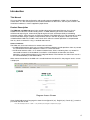
When remote connection to the HMS unit is established from the control PC, the program access screen
is displayed:
Program Access Screen
Once the desired program language has been chosen [Spanish (es), English (en), French (fr) ], enter the
password and click on OK.
Note: The default password — admin — can (and must) be changed as explained on page 9.
4
Chapter One - Configuration of the Control Unit
In this Chapter
●
Configuration of General System Parameters
●
Configuration of Internal GSM/GPRS Modem
●
Configuration of Remote Access
●
Configuration of RF Levels Monitor System
●
Configuration of SMS Alarm Sending System
●
Configuration of NIT
●
Save/Recover Settings
5
Configuration of General System Parameters
Configuration of General System Parameters
Initial program screen
The first screen which appears
when you access the program
contains the window entitled
"Headend status overview",
which provides full information
about the current configuration
and status of all of the headend
modules interconnected with the
HMS unit via the IKUSUP bus.
On the left of the screen are the
menus that access all of the
program's functions.
Figure 1.1 - Program initial screen
Click on the Configuration menu on the left of the screen to display a dropdown list
containing the 7 options: System, Modem, Remote Access, RF Level Monitor, Alarms,
NIT and Save/Recover.
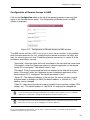
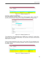
Click on System. The Configuration of General System Parameters window is
displayed:
Figure 1.2 - Identification card of the Config. of General System Parameters window
Identification
The Identification card (Figure 1.2) contains basic identification data for both the control
unit and the headend station. The various fields of the card are filled in as follows:
6
Configuration of General System Parameters
"Model": This shows the name of the control unit installed in the headend: HMS120 or HMS-130. Obviously, this information cannot be changed.
"Serial Number": For the installed HMS unit. This cannot be changed either.
"Firmware Version": For the installed HMS unit. Ditto.
"Headend Identification": Any name that the installer or operator wants to assign to
the headend station can be entered here.
"Address": Enter the postcode of the installation site if desired. If the control PC is
connected to the Internet at the time, click on Show map to view a map showing the
site.
"Installer": You can enter the installer's identification data.
"Contact": Again, enter their contact details (telephone number, email).
"Installation date": Here you can enter the headend start-up date.
Once you have entered the information, click on Send at the bottom of the window to store them in the HMS unit. If,
at the last moment, you decide not to change the existing information, click on Cancel.
System time
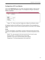
Click on the System Time tab. The following card is displayed:
Figure 1.3 - System Time card of the Config. of General System Parameters window
"Module to be used as time reference" : Select the headend module which will
provide the date and time that the HMS unit will use as the reference for all control
operations. (The date and time given by each of the modules are taken from their
reception signals).
"Time zone" : Click on the dropdown list and select the timezone of the installation
site.
"Subzone" : Select the subzone.
Once you have done the three selections, click on the Send button so that the HMS unit adopt the new time
reference. If, at the last moment, you decide to keep the previous one, click on Cancel.
7
Configuration of General System Parameters
Network
If you want to configure the Ethernet network connection parameters of the HMS unit,
click on the Network tab. The following card is displayed (Figure 1.4).
!
This card will only be filled in if the headend station is integrated in a local Ethernet network.
Note
Figure 1.4 - Network card of the Configuration of General System Parameters window
"MAC Address": The physical address of the HMS unit network card is displayed
automatically.
"Use DHCP to get IP address": If this box is ticked, the HMS unit will use the DHCP
protocol for assigning dynamic IP addresses. Consequently, no data needs to be
entered in the next five fields on the tab.
If the administrator of the network in which the headend is installed assigns static
IP addresses, the box will not be ticked and the fields will need to be filled in.
ATTENTION; If this option is activated, you will only be able to know the IP address
assigned to the HMS unit by consulting the management system of the DHCP
server.
"IP Address": Enter the IP address that you want to assign to the HMS unit. This
address must fall within the range of local network addresses.
"Network mask": Enter the local network mask.
"Default gateway": Enter the IP address of this gateway.
"Primary DNS server": Enter the server's IP address. This information is only
required if you want the HMS unit to access Internet.
"Secondary DNS server": Enter the server's IP address. As above, this information
is only required if you want the HMS unit to access Internet.
Once you have filled in all of the required information, click on Send. If, at the last moment, you decide to keep the
previous data, click on Cancel.
8
Configuration of General System Parameters
Password
If you want to change the current program password, click on the Password tab. The
following card is displayed:
Figure 1.5 - Password card of the Config. of General System Parameters window
"Current password": Enter the current password.
"New password": Enter the new password which will be required to access the
program the next time.
"Confirm new password": Re-enter the new password.
Once you have entered the required information, click on Send so that the HMS adopts the new access password. If,
at the last moment, you decide to keep the previous password, click on Cancel.
!
Note
If you do not know the old password, i.e. the password used to access the current monitor session,
you must perform a Password Reset as explained in Section 1 of the Installation and Access
manual. Following this reset, the program password will be the default password: admin.
IMPORTANT: When you perform a password reset, the IP address assigned to the unit on the
Network card (previous page) automatically changes to the default one: http://192.168.1.4.
Shutdown
If you need to reboot the control unit for any reason, click on the Shutdown tab. The
following card is displayed:
Figure 1.6 - Shutdown card of the Config. of General System Parameters window
Click on Reboot HMS. The program's initial screen is displayed (Figure 1.1, pag. 6).
9
Configuration of General System Parameters
HMS Firmware
If you want to update the control unit firmware, click on the HMS Firmware tab. The
card of Figure 1.7 is displayed. It shows at the top the firmware version installed in the
control unit at the present time.
(The firmware is software stored in the module which is responsible for its basic operation).
Figure 1.7 - HMS Firmware card of the Config. of General System Parameters window
WARNING: The firmware update file will have been previously stored on the PC hard
drive. (You can download it from http://www.ikusi.com).
Click on Browse... and select the firmware file available for updating on the hard drive.
When the name appears in the box, click on Send. The new firmware will be installed in
the HMS unit. If, at the last moment, you decide to not to update, click on Cancel.
10
GSM Modem Settings
GSM Modem Settings
Click on the Configuration menu on the left of the general program screen and click
again on the Modem option. The GSM Modem Settings window is displayed:
Figure 1.8 - Status card of the GSM Modem Settings window
As well as accessing the control unit via GSM, the internal modem can send SMS alarm
messages and various information.
Status
The Status card (Figure 1.8) provides the following information:
"PIN": A tick means that the modem has stored the PIN (personal identification
number) previously entered from the Configure tab (see next page).
"GSM Network": This specifies whether the modem is or is not registered in a GSM
network.
"Signal level": Shows the GSM signal level.
"Bit Error Rate": Shows the BER.
"SMS sending status": A tick means that the SMS sending service is working
properly.
!
Note
The HMS unit must have the modem's SIM card installed and the supplied GSM aerial connected.
Please refer to the Installation and Access manual.
11
GSM Modem Settings
Configure
So that the GSM modem is activated each time the monitor program boots, the HMS
unit must have stored the PIN for the inserted SIM card (subscriber identity module).
Click on the Configure tab. The following card is displayed:
Figure 1.9 - Configure card of the GSM Modem Settings window
"PIN": Enter the PIN for the SIM card.
Next, click on Send so that the PIN entered is stored in the HMS unit. If, at the last moment, you decide not to change
the previous PIN, click on Cancel.
Test
In order to test SMS sending by the HMS unit, click on the Test tab. The following card
is displayed:
Figure 1.10 - Test card of the GSM Modem Settings window
"Message": Enter the text of the test SMS.
"Telephone number": Enter the telephone number that will receive the message
(this number must include the country dialling code: +34 Spain, +33 France, etc.).
Once you have filled in all of the required information, click on Send test message. The program automatically goes
back to the Status tab (Figure 1.8, previous page), where a message is displayed at the top announcing that the
telephone will receive the message shortly. If the message does not arrive within 2 minutes, check on the last line of
the tab to see whether an SMS sending error has occurred.
12
Configuration of Remote Access
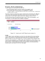
Configuration of Remote Access to HMS
Click on the Configuration menu on the left of the general program screen and click
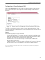
again on the Remote Access option. The Configuration of Remote Access to HMS
window is displayed :
Figure 1.11 - Configuration of Remote Access to HMS window
The HMS control unit has a PPP (Point-to-Point Protocol) server function. In this window
enter the data necessary for, first, establishing the remote connection via GSM, and
next, for accessing the unit (see "Establishing remote connection" in section 2 of the
Installation and Access manual).
"Username": Enter the name that must be entered in the field with the same name
("Username") when the Telephone access to networks application of the remote
control PC is configured. The default name is "test".
"Password": Enter the password that must be entered in the field with the same
name ("Password") when the Telephone access to networks application of the
remote control PC is configured. The default password is "test".
"Server IP": The displayed address is the one that the control unit has currently
assigned when is acceded via GSM (the default address is 169.254.9.1). This
address can be changed
"Client IP": Idem that of the device used to establish the connection (modem, PDA,
cellular, etc.). This default address is 169.254.9.101 and may be changed too.
!
Note
!
Note
To prevent that people knowing the equipment can accede it via the telephone access to networks
application, it is advisable to change the default name and password keys ("test").
The subnet sections of the server and client IP addresses have to be equal (mask 255.255.255.0).
Take it into account if you opt for changing one or the two addresses.
Once you have filled in the information, click on Send. If, at the last moment, you decide to keep the previous
username and password, click on Cancel.
13
Configuration of RF Level Monitor
Configuration of RF Level Monitor
Click on the Configuration menu on the left of the general program screen and click
again on the Signal Level Monitor option. The Configuration of Signal Level Monitor
window is displayed:
Figure 1.12 - Status card of the Configuration of Signal Level Monitor window
An important function of the HMS unit is RF level monitoring. The unit provides the
signal levels of each channel at both the loop-through input and output of the headend
station.
Status
The Status card (Figure 1.12) provides a summary of the level monitor built into the
control unit. An important feature of this information is the internal temperature of the
unit.
"Model": The name assigned to the level monitor built into the unit is given.
"Firmware Version": The firmware version of this model.
"Hardware": A tick means that the hardware works properly.
"Temperature": The internal temperature of the control unit.
14
Configuration of RF Level Monitor
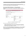
Configuration
The control unit provides the multichannel output signal level of the station based on a
sample signal connected to the RF IN port of the unit. Click on the Configure tab. The
following card is displayed:
Figure 1.13 - Configure card of the Configuration of Signal Level Monitor window
"Tap value": Enter the value in dB of the tap attenuation presented by the device
providing the sample signal.
Once you have entered the information, click on Send. If you do not want to change the current tap value, click on
Cancel.
!
Note
A ClassA station always includes an RF power amplifier, the output of which is the station’s own.
Although an external amplifier can be used, an HPA module from the ClassA family is usually used.
HPA modules have a -30 dB output test port which can be connected to the RF IN port of the control
unit. The test signal is used as well as the sample signal for the signal monitor. (Please refer to the
Installation and Access manual).
15
Configuration of Alarm Sending via SMS
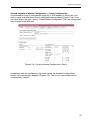
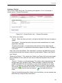
Configuration of Alarm Sending via SMS
Click on the Configuration menu on the left of the general program screen and click
again on the Alarms option. The Configuration of Alarm Sending via SMS window is
displayed:
Figure 1.14 - General card of the Configuration of Alarm Sending via SMS window
The HMS unit continuously monitors a series of station operating parameters. If any
value falls outside the set operating limits, the unit automatically sends an alarm SMS to
a specific telephone.
General
The General card (Figure 1.14) has four fields:
"Activate SMS notification": Tick the box if you want to activate the sending service.
"SMS receiver phone number": Enter the phone number that will receive the alarm
messages. The number must include the country dialling code.
"SMS prefix text": If you want the message to include a prefix to identify the
message easily, enter it here.
"Repeat notification": The HMS can repeat a notification until the cause of the alarm
has been solved. Click on the dropdown list and select the repeat frequency.
Once you have filled in the various fields, click on Send. If, at the last moment, you decide to keep the previous
settings, click on Cancel.
16
Configuration of Alarm Sending via SMS
Alarms
Alarm messages are related to several elements and parameters of the station modules
and headend. Click on the Alarms tab. The following card is displayed:
Figure 1.15 - Alarms card of the Configuration of Alarm Sending via SMS window
The card shows six sections that refer to other parameters that the control unit can
monitor to send SMS alarm messages:
"Temperature monitor": Tick the box if you want the unit to send an SMS when its
internal temperature exceeds the minimum and maximum limits established in the
two boxes in this section. For information purposes, this internal temperature is
7(±2) °ºC above room temperature.
"Detected Modules Monitor": Tick the box if you want the unit to send an SMS when
the number of detected modules is different to the one entered in the box
underneath. This alarm indicates breakdown or theft. (The number of modules
always refers to the modules interconnected via the IKUSUP bus, without including
the HMS unit).
"Communication Bus Control": Tick the box if you want the unit to send an SMS
when the error rate in the IKUSUP bus traffic suggests that there is a fault in the
headend station.
"Input Sync Monitor": Tick the box if you want the unit to send an SMS when there
is a loss of synchronism with the input signal in any of the headend modules.
"Module's Alarms Monitor": Tick the box if you want the unit to send an SMS when
any of the module alarms is activated.
"Single Channel Output Levels": Tick the box if you want the unit to send an SMS
when the output level of any station channel is outside the limits established in the
boxes underneath.
Once you have checked the boxes, click on Send. If you do not want to change the previous settings, click on
Cancel.
17
Configuration of NIT
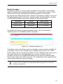
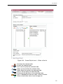
Configuration of NIT
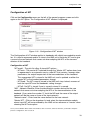
Click on the Configuration menu on the left of the general program screen and click
again on the NIT option. The Configuration of NIT window is displayed:
Figure 1.16 - Configuration of NIT window
The Configuration of NIT window applies to headends with digital transmodulator modules. It is used to regenerate and/or to store in the HMS unit a particular NIT and to give
a name to the new network that comes out when adapting the NITs of the transmodulators of the headend.
Configuration of NIT
"NIT mode" : The pick list offers 3 stored-NIT options :
- NIT-auto : The master NIT selected through the "Master NIT" option down here
is regenerated in an automatic way to a new NIT that contains, amongs other
parameters, the output frequencies of the transmodulators of the headend.
This regenerated NIT is stored in the HMS unit, and is updated as either the
master NIT or the headend parameters change.
- NIT-fixed : The NIT currently stored in the HMS unit stays locked, unaware of
both the input NITs and the headend's setting changes.
- NIT-off : No NIT is stored. If one is currently stored, it is erased.
"NID" : Network IDentifier. Enter the identification number desired for the new
network that comes out when adapting the NITs of the transmodulators of the
headend. (If you enter the number "0", both the NID and the name of the output
network will be the same as those of the input network).
"Network name" : Enter here the name desired for the new network.
"Master NIT" : Click on the dropdown list and select the transmodulator module
whose input NIT will be considered by the HMS unit as reference or "master" when
choosing the NIT-auto option.
Once you have filled in all the fields of the window, click on Send. If, at the last moment, you decide to keep the
previous configuration, click on Cancel.
18
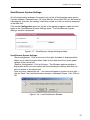
Save/Recover System Settings
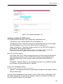
Save/Recover System Settings
All of the information entered in the control unit via the 6 Configuration menu options
(System, Modem, Remote Access, RF Level Monitor, Alarms and NIT) can be saved on
a backup file. Inversely, the settings information saved on a file can also be recovered
in the HMS unit.
Click on the Configuration menu on the left of the general program screen and click
again on the Save/Recover System Settings option. The Save/Recover System
Settings window is displayed:
Figure 1.17 - Save/Recover System Settings window
Save/Recover System Settings
"Save configuration": Click on the icon to the right. A window is displayed which
allows you to select the destination folder for the data file of the current global
settings of the control unit.
"Recover Configuration": Click on Browse... The Windows explorer window is
displayed in which you must select the file containing the settings data that you
want to recover in the control unit.
Once you have selected the file — the name will appear in the box on the right —,
click on Send. The Load Confirmation window is displayed (Figure 1.18). Click on
OK.
Figure 1.18 - Load Confirmation Window
19
Chapter Two - Module Monitor
In this Chapter
●
Monitoring and Adjustment
●
Module Configurations
●
OSD Configurations
●
Module Scheduler
●
OSD Scheduler
●
RF Signal Levels — Monitor and Equalisation
●
Firmware — Updates — Scheduler
●
INFO channel (exclusively for HMS-130)
20
Monitoring and Adjustment
Controlling the Headend Modules
The HMS unit allows all of the headend modules that are interconnected to it to be
controlled remotely via the IKUSUP communications bus. Click on the Headend menu
on the left of the general program screen to display a dropdown list containing the
following 5 or 6 options: Modules, Configurations, Scheduler, RF Signal Equalizer,
Firmware and, only for HMS-130, INFO Channel.
Click on Modules. The Headend Status Overview window is displayed:
Figure 2.1 - Headend Status Overview window
This window shows the main adjustment and selection parameters for each of the
headend modules and states whether there are any problems in them. In order to
provide a better description of the various components, identification numbers have
been used (Figure 2.1):
➀ The headend modules are represented by rectangles with a strip at the top which
shows the module's order number in the IKUSUP bus and the module name. The
strip is Green if the module is working properly or Red if it is in an alarm status.
➁ The middle strip of the rectangle shows the values of the four important module
parameters.
➂ The bottom strip contains the 4 actions that can be carried out on each module
through this window:
21
Monitoring and Adjustment
Settings. When this action is selected, the Parameters Control Module #
window is displayed (see next page), through which all of the module parameter
settings can be consulted and changed and information about its status can be
retrieved.
Levels. When this action is selected, the RF Signal Levels window is displayed
(see page 44), which shows the RF levels of each channel at both the loopthrough input and the headend station output. The window also allows you to
equalise the RF bandwidth level of any of these signals or, more specifically,
run a multi-module AGC so that each single channel level stays within set limits.
Reset. When this action is selected, a reset order is sent to the module which
changes all of the adjustment and selection parameters to the default ones.
LED on / LED off. This shows
whether the red STATUS led
on the front panel of the module is on or off. When this
action is selected, the led
switches on or off, making it
easier to identify the module in
the headend.
➃ Red bar showing the automatic updating of all the information displayed in the
window. The update takes place every 10 seconds.
➄ Incompatible data. When two or more modules have a same output channel
frequency established, the number is shown in red on a yellow background.
22
Monitoring and Adjustment
Modules — Parameters Control
When you click on the Settings action in the rectangle representing a specific module in
the Headend Status Overview window, the Parameters Control Module # (windows is
displayed (Figure 2.2). From the five tabs in this window you can consult and change
all of the settings and selections of the chosen module.
Settings
Click on the Settings tab. The following card is displayed:
Figure 2.2 - Settings card of the Module's Parameters Control window
The card shows the parameter values related to four specific module sections: Input,
V/A Selections, Output and Others.
The process to change a parameter value or selection is simple. The following explains
how to change the module input frequency, the current value of which is 1354 MHz.
!
Note
The figures shown on this page and the following refer to an SDC-M102 module. The tab
for other models is similar, and at any rate it is structured in the same way as local
programming with the SPI-300 command. Therefore, you are recommended to keep a
copy of the Basic Operation manual at hand, as well as the module Programming Guides.
You can download these from http://www.ikusi.com.
When the module is a digital transmodulator with TS Processing, the Settings card has a
special section ("NIT") which is explained on page 25.
23
Monitoring and Adjustment
Enter the new value desired for the input frequency in the relevant box. The line is
highlighted in red. You will also notice that the frames of the selection boxes in the
V/A Selections section on the right disappear (Figure 2-3).
Once you have changed the input frequency (and other parameters if required), click on
Send (there are two on the card, one at the top and one at the bottom) so that the
change is applied in the module. Once you have clicked this, a message appears at the
top of the tab stating that the changes are being sent (Figure 2-4). When the module in
question has received the changes, the sending message disappears, as does the red
highlight of the changed parameters. The selection boxes in the V/A Selections section
reappear. You must now select the desired video and audio services for the input
channel. Another sending message should appear when you click on Send.
Figure 2.3 - Settings — Parameter change card
Figure 2.4 - Settings — Sending changes card
24
Monitoring and Adjustment
Note about the Settings card for the digital transmodulator modules
The Settings card for the digital transmodulator modules has three sections: Input, Output
and NIT. The options of the last, NIT, are explained below.
Figure 2.5 - Settings card of the MDI-900 transmodulator
"NIT" :
- NIT Mode :
The dropdown list has 3 options:
- NIT-auto : The NIT of the transmodulator module is at any time the same as
the one stored currently in the HMS control unit.
- NIT-fixed : The current NIT of the transmodulator module stays locked,
unaware of any change of either its input NIT or the NIT stored in the HMS
unit.
- NIT-pass : The output NIT is at any time the same as the input NIT. Any NIT
stored in the module is erased.
25
Monitoring and Adjustment
Info
Click on the Info tab. The following card is displayed:
Figure 2.6 - Info card of the Module's Parameters Control window
This card contains three sections — Status, Alarms and Details — which provide
information about the module. The data displayed is updated every 10 seconds, as
mentioned earlier.
Scheduler
Click on the Scheduler tab. The following card is displayed:
Figure 2.7 - Scheduler card of the Module's Parameters Control window
This card shows the adjustment changes scheduled for the next 7 days (see Scheduler
on pages 33 to 39).
26
Monitoring and Adjustment
Transport Stream Processing
The TS Processing tab only appears for digital transmodulator modules with TS
processing function. When you click on this, the following card is displayed:
Figure 2.8 - TS Processing card of the Module's Parameters Control window
The card has three fields: TS Treatment, Unreferenced PIDs and Information.
"TS Treatment" :
It includes three sections —Services, Conditional Accesses, PIDs— through
which you can block or unblock services, conditional accesses or PIDs, as well
as force PIDs (*). The process is very simple: 1.Click on the "+" icon on the left of
the section, Services for example, so that a window apperars showing, in this
case, all the services available (Figure 2.9); 2.Select the services you want to
block or unblock; 3.Select in the Action dropdown list the desired action (to block
or to unblock); 4.Click finally on the Send button.
Figure 2.9 - TS Processing card — Services window
The current status of the Services, CAs and PIDs is displayed at the last column of
the pop-up window through icons whose meaning is indicated in a box at the
bottom of the card.
* See Concerning information on the next page.
( )
27
Monitoring and Adjustment
"Unreferenced PIDs" :
The Action dropdown list offers three options for the unreferenced PIDs existing
in the input transport stream:
- Auto : The transmodulator itself decides what to do with the unreferenced
PIDs, either to block or let pass them.
- Block : All the unreferenced PIDs are blocked.
- Permit : All the unreferenced PIDs are let pass.
Once the selection is made, click on Send.
"Information" :
Output TS — % Free.
Here is indicated what the output TS is unoccupied, in other words, the
percentage of null PIDs in the TS. The higher is the number, the lower overflow
risk.
Concerning information
Unreferenced PIDs : The unreferenced PIDs are PIDs that are not related to any table,
CA or service.
Null PIDs : Or stuffed PIDs, are PIDs that contain no information.
Block Service : When a service is blocked, all the related PIDs —video, audio, teletext
and others— are blocked and the tables are updated.
Block Conditional Access : When a CA is blocked, the PIDs of the ECM and EMM are
blocked and the tables are updated.
Block PID : When a PID is blocked the tables are not updated.
Force PID: To force a PID is to enable a PID, either referenced or not, which could be
blocked as a consequence of the blockade action for a determined service or CA, or the
blockade of unreferenced PIDs. This action may also be used to invalidate a by-default
regenerated PSI/SI table, and to restore the original one.
28
Monitoring and Adjustment
Conditional Access
The Conditional Access tab only appears in receiver modules that have embedded or
common interface conditional access. When you click on this, the following card is
displayed:
Figure 2.10 - Conditional Access card of the Module's Parameters Control window
If you want to make changes to the current module conditional access settings, click on
Start conditional access session. The first of various screens that the program uses to
configure access will appear.
BISS scrambling
The BISS scrambling tab only appears in receiver modules. When you click on this, the
following card is displayed:
Figure 2.11 - BISS Scrambling card of the Module's Parameters Control window
If you want to make any changes to the Mode or System passwords, proceed as
described earlier.
29
Monitoring and Adjustment
OSD
The OSD tab is related to the generation of OSD messages by the modules. When you
click on this, the following card is displayed :
Figure 2.12 - OSD card of the Module's Parameters Control window
The card has three sections:
"OSD settings" : Indicates whether the module has the OSD mode put out (✖) or
put in (✓), that is to say, if as indicated on the third line, the supplied video signal is
TV image (DVB) or OSD text. If the OSD mode is currently put in, a Putting Out
OSD button appears on the second line; the button allows to put the mode out
directly.
"OSD Options" : Two boxes for two options. Tick the first one and click on the Send
button if you want to activate in the module, at this moment, the OSD message
written in the OSD Parameters section below (Figure 2.12 shows these lines
empty). The second box will be ticked to create OSD configurations and/or OSD
schedules (see pages 36 and 40).
"OSD Parameters" : The desired OSD text is edited here, on the seven lines
available. The background will be transparet or black depending on you tick or not
the box above. The colour of the characters is white by default, but it may be
changed in each line; for that, click on the square buttons at the right and select the
colour in the popup menu.
30
Module Configurations
Creating Configurations for Making Schedules
The HMS unit allows to create schedules for each module of the headend. Scheduling
may be either for parameter settings or for OSD messages. To do it, you must create
previously the so called Module Configurations and OSD Configurations.
Module Configurations
"Module Configurations" refers to a set of values for all of its adjustment and selection
parameters. The configurations are used to perform module schedules (pages 37 to
39).
The module configurations creation process can be described more clearly by giving
examples.
!
Note
The windows in the examples refer to an SDC-M102 module. The windows for other models
are similar, and at any rate it is structured in the same way as local programming with the
SPI-300 command. Therefore, you are recommended to keep a copy of the Basic
Operation manual at hand, as well as the module Programming Guides. You can download
these from http://www.ikusi.com.
First example of Module Configuration — Prepare settings
The aim is to create an SDC module configuration with the channel WDR Aachen in
channel 21 (471.25 MHz), with the rest of the adjustment parameters properly defined.
The first step is to assign an SDC module of the headend for the operation. The
parameters of this module will be adjusted to the values defined for the configuration
using the Settings tab in the Parameters Control Module # window (pages 23/24).
Figure 2.13 shows the card, on which all of the settings defined for the configuration
have been established:
Figure 2.13 - Creating First Configuration. Step 1.
31
Module Configurations
Once you are sure that all of the parameter values that appear on the card are
established in the headend module and are defined for the configuration to be created,
click on "Save these settings as new module configuration".
First example of Module Configuration — Saving configuration
When you click on "Save these settings as new module configuration", a form is
displayed in the same area (Figure 2.14) through which the definitive configuration is
created:
Figure 2.14 - Creating First Configuration. Step 2.
Fill in the two "New Module Configuration Data" fields:
"Module Configuration Name": Enter a short, clear name for the configuration.
"Module Configuration Description": Describe the configuration using the name
entered above or a wider expression if desired.
Next, click on Create Module Configuration. The configuration is saved in the HMS unit
and the screen brings up automatically the Available Configurations window (Figure
2.15, next page), which displays all the Module and OSD configurations stored
currently in the HMS unit.
32
Module Configurations
Available Configurations window
This window (Figure 2.15) is displayed automatically once a new configuration has
been created (*), either for Module or for OSD. This displays all the configuraions stored
currently in the HMS unit :
Figure 2.15 - Available Configurations window
To the left of each line on the list there are three icons relating the following actions:
Edit: If you want to change the configuration name or description, click on the first
icon.
Download to PC: Click on the second icon to download a file containing the
configuration data to the PC.
Delete: If you want to delete the configuration, click on the third icon.
As well as the aforementioned icons, at the top of the screen there is the option "Load
new configuration from PC". When you select this, a form is displayed on which you
can select and send a configuration file that is stored in the PC to the HMS unit.
!
Note
The Download to PC and Load from PC options allow you to create configurations in one
headend and use them in another.
( )
* You can open the Available Configurations window at any time by clicking on the
Headend ➝ Configurations option from the menu on the left of the general program
screen (Figure 1.1, pag . 6). This window provides a list of all the configurations
currently stored in the HMS unit.
33
Module Configurations
Second example of Module Configuration — Preparing settings
The configuration being created this time is another SDC module configuration with the
channel WDR Essen in the same channel as the previous one, 21. The transponder is
the same as for WDR Aachen, which means that the input frequency is the same. The
other parameters must be defined properly, as in the first configuration.
To create the configuration, the same SDC module used for the first configuration will
be assigned. If the input frequency needs to be changed, the first step would be to
change it in the Settings tab (Figure 2.16) and then run the Send command. Once the
new frequency has been established in the module (which is not the case in the
example), the channel WDR Essen and the other parameters can be selected in the
A/V Selections section (Figure 2.17). Click on Send again.
Figure 2.16 - Creating Second Configuration. Step 1.
Figure 2.17 - Creating Second Configuration. Step 2.
Once all of the parameter values which appear on the Settings tab are established in
the headend module and you have checked that they are defined for the configuration
to be created, click on "Save these settings as new module configuration".
34
Module Configurations
Second example of Module Configuration — Saving configuration
As explained for the first configuration (page 32), a form appears in which you must
enter a name and description for the configuration being created (Figure 2.18). Once
you have filled in the form, click on Create Module Configuration. The new configuration
will be saved in the HMS unit.
Figure 2.18 - Creating Second Configuration. Step 3.
Immediately after the configuration has been saved, the Availabe Configurations
window will automatically reappear (Figure 2.15) . The list will now include the two
configurations created.
35
OSD Configurations
OSD Configurations
An "OSD configuration" is simply a determined text message. The OSD configurations
are used to perform OSD schedules (pages 40 and 41).
An OSD configuration is carried out through the OSD card. First edit the desired
message in the OSD Parameters section. Next, at the OSD Options section, click on
the "Save and create a schedule". The "New OSD Configuration Data" form is displayed
at right :
Figure 2.19 - OSD card — Creating OSD Configuration
Fill in the two fields of the form :
"OSD configuration name" : Enter a short name that identifie clearly the message.
"OSD configuration description" : Describe the configuration using the name
entered above or a wider expression if desired.
Next, click on the Send button below. The configuration is saved in the HMS unit and
the screen brings up automatically the Available Configurations window, which will
include the OSD configuration that has been just created :
Figura 2.20 - Available Configurations window
36
Module Scheduler
Module Scheduler
The HMS unit allows you to plan module schedules in every module of the headend.
Module schedules refer to automatically changing —on preset time and date— of the
value of one or several adjustment and selection parameters of the module.
By using the two module configurations created in the examples on pages 31 to 35, the
following example explains the process required to apply the following daily schedules
in an SDC-M102 module, which ranks number 2 on the headend station:
Time frame
Channel
Output channel
09:00 to 22:00
WDR Aachen
21 (471.25 MHz)
22:00 to 09:00
WDR Essen
21 (471.25 MHz)
On the left-hand menu of the general program screen, click on the Headend ➝
Scheduler option. The Scheduler window is displayed:
Figure 2.21 - Module Scheduler (I-a)
The Settings card of this window shows the schedules currently stored in the HMS unit.
In the figure, none exist yet. To apply the two schedules given above in the "2 SDCM102" module, click on "Create new schedule". A form is displayed in the same area of
the window (Figure 2.22, next page) which you must fill in for each of the two
schedules, the one for the channel WDR Aachen and the one for the channel WDR
Essen, both of which are in UHF channel 21. The configurations will be requested and
will be the two created on the previous pages.
!
Note
In order to create a schedule, the corresponding module configuration has to be stored
previously in the HMS unit.
37
Module Scheduler
Figure 2.22 - Module Scheduler (I-b)
Creating a schedule for WDR Aachen
Fill in the three fields existing in the Configuration and Module form:
"Configuration type": Select Module from the dropdown list.
"Configuration name": Select the name of the configuration that you want to apply
from the dropdown list (in this case, "WDR Aachen in channel 21").
"Apply to module (s)": The popup window shows all of the SDC-M102 modules in
the headend. Select module number 2.
(The list only shows the SDC-M102 models that exist in the headend since the configuration
selected from the previous dropdown list corresponds to this module model).
Next, fill in the Start section:
Start "Date" and "Time": Enter the date and time which will change the adjustment
and selection parameters of the "2 SDC-M102" module to those defined in the
selected configuration. In the example, today's date and the time 09:00 are
entered.
"No repeat" / "Repeat": Refers to the scheduled change. As the scheduled change
must be daily, the affirmative option is selected.
Finally, fill in the Repeat Pattern:
(Note : This section does not appear if you selected "No repeat" above)
"Repeat": The frequency with which the parameter change must be applied. Select
Daily and Every day.
Once you have completed all of the sections, click on Send. The form disappears and
the window displays the list of existing schedules, which will include the one that you
have just created (Figure 2.23, next page).
38
Module Scheduler
Figure 2.23 - Module Scheduler (I-c)
Creating a schedule for WDR Essen
Click on "Create new schedule" (Figure 2.20). The form appears again, in which you
must fill in the information relating to the schedule for WDR Essen (Figure 2.24):
Figure 2.24 - Module Scheduler (I-d)
The configuration to be selected this time is "WDR Essen in channel 21", which will be
applied to the same module (2 SDC-M102). The start time in this case is 22:00 and the
repeat pattern is also daily.
Once you have completed all of the sections, click on Send. The form disappears and
the window displays the list of existing schedules, which will include the two ones that
have been created:
Figure 2.25 - Module Scheduler (I-e)
39
OSD Scheduler
OSD Scheduler
The purpose of OSD schedules is to generate —on preset time, date and duration—
OSD messages on the part of selected modules of the headend. These messages will
have been previously stored in the headend as OSD Configurations (page 36).
OSD schedule creation procedure is similar to that explained for Module schedules. On
the left-hand menu of the general program screen, click on the Headend ➝ Scheduler
option. The Scheduler window is displayed :
Figura 2.26 - OSD Scheduler (I-a)
The Settings card of this window shows the schedules currently stored in the HMS unit.
In the figure, none exist yet. To apply one OSD schedule to one or several modules of
the headend, click on "Create new schedule". A form is displayed in the same area of
the window :
Figure 2.27 - OSD Scheduler (I-b)
40
OSD Scheduler
Fill in the three fields existing in the Configuration and Module form:
"Configuration type": Select OSD from the dropdown list.
"Configuration name": Select the name of the OSD configuration that corresponds
to the desired OSD.
"Apply to module (s)": The popup window shows all the modules of the headend.
Select the module (s) to which you want to apply the OSD schedule.
Next, fill in the Start section :
Start "Date" and "Time": Enter the date and time as of which the selected modules
will transmit the selected OSD message.
"No repeat" / "Repeat": Refers to not endow or endow with periodicity the message
displaying.
Fill in the Duration section :
"Days", "Hours" and "Minutes" : Enter the desired duration of the OSD message.
Finally, fill in the Repeat Pattern:
(Note : This section does not appear if you selected "No repeat" above)
"Repeat": The frequency with which the message appears.
Once you have completed all of the sections, click on Send. The form disappears and
the window displays the list of existing schedules (as Module's as OSD's), which will
include the one that you have just created:
Figure 2.28 - Settings card of the Scheduler window (I-a)
41
Scheduler
Activate/Deactivate Schedules
The list of schedules stored in the HMS unit can be accessed at any time by clicking on
the Headend ➝ Schedules option on the menu to the left of the general program
screen. A window similar to the one shown in Figure 2.28 on the previous page will be
displayed.
A schedule can be deleted from the memory by clicking on the icon on the extreme left
of the line. A less drastic option is to deactivate it, allowing you to keep it in the memory
for future use.
The schedule can be activated (deactivated) by clicking on the icon above the word
Deactivated (Activated). Deactivated schedules are highlighted in yellow and activated
schedules are highlighted in white :
Figure 2.29 - Settings card of the Scheduler window (I-b)
Firmware Update Schedules
Although the creation of this type of schedules is not carried out from Headend ➝
Schedules, but from Headend ➝ Firmware, they are mentioned here because these
schedules are included together with the Module's and OSD's ones in the information
provided by the Scheduling card (next page).
The modus operandi to create these schedules is different to that explained for Module
and OSD, since it is not necessary to create previously any type of configuration. The
procedure is more direct and is explained in the Firmware section (pages 46 to 48).
42
Scheduler
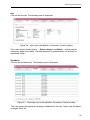
Scheduling
To find out the changes scheduled for the next 7 days, click on the Scheduling tab. The
following card is displayed :
Figure 2.30 - Scheduling card of the Scheduler window
The card can show either all the existing schedules or those of each type separately
(Module, OSD or Firmware). Select the desired option in the dropdown list above and
next click on Apply filter.
43
RF Signal Levels
RF Levels - Monitor and Equalisation
Two RF signals are connected to the HMS unit:
a) the multichannel output connection signal of the modules; and
b) a tap signal taken from the output of the headend RF amplifier.
(Usually, the amplifier is an HPA module and the tap signal used is the output test signal, as explained in the
Installation and Access manual).
The levels of the two multichannel signals mentioned are monitored by the HMS unit,
which shows them separately, channel by channel. Also, the unit includes an AGC
system that can control each single channel level, keeping it within set limits.
On the left-hand menu of the general program screen, click on the Headend ➝ RF
Levels option. The RF Signal Levels window is displayed:
Figure 2.31 - Levels card of the RF Signal Levels window (I-a)
Levels
The RF Signal Levels card displays two levels for each channel: the output coupling
signal of the modules (or loop-through input signal) and the headend output signal.
Both are shown on a bar chart (Figure 2.31): the first in green and the second in blue.
At the top of the card there is a "Select graph data" dropdown list, which allows you to
select a specific headend module in order to obtain a graph showing the progress, over
the last 2 hours, of the module output channel signal levels at the aforementioned
headend points (see Figure 2.32 on the next page).
44
RF Signal Levels
Figure 2.32 - RF Signal Levels card of the RF Signal Levels window (I-b)
Automatic Gain Control
Click on the Automatic Gain Control tab. The following card appears:
Figure 2.33 - Automatic Gain Control card of the RF Signal Levels window
The card is divided into three sections:
"Activate AGC": Check the box if you want to activate the AGC system.
"Reference HMS input to be used by AGC": Select RF Input if you want the system
to operate in accordance with the output tap signal level. Select Loop-through input
if you want it to operate in accordance with the loop-through input signal level of the
HMS unit.
Desired signal levels: Use the cursor to enter the maximum and minimum values
desired for both analogue and digital channels at the selected port (RF input or
loop-through input).
Once you have filled in the various fields, click on Send. If, at the last moment, you decide to keep the current values,
click on Cancel.
45
Firmware
Firmware Management
The HMS unit provides full information about the headend module firmwares and allows
these to be updated.
On the left-hand menu of the general program screen, click on the Headend ➝
Firmware option. The Firmware Updates window is displayed:
Figure 2.34 - Firmwares Info card of the Firmware Updates window (I-a)
Firmwares Info
The Firmwares Info card (Figure 2.34) displays a list of the firmwares of the headend
modules, identified by model name and serial number, as well as of the updating files
available currently in the HMS unit.
Files Uploaded
Click on the Files Uploaded tab. The card displayed (Figure 2.35) shows a list of the
files that the unit has stored and the module models that apply:
Figure 2.35 - Files Uploaded card of the Firmware Updates window (I-a)
There are two icons on the left of each line on the list:
"Delete": When you click on this icon, the firmware file is deleted from the unit's
memory.
"Download": Click on this icon to download the file to the PC.
46
Firmware
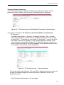
Uploading a firmware file to the HMS unit
To be able to update the firmware of one module, the corresponding file has to be
stored in the PC's hard disc. Starting from here, the first operation is to load it into the
HMS control unit..
On the Files Uploaded card (Figure 2.32, previous page), click on "Upload new file".
The "Select file" field is displayed in the same area (Figure 2.36):
Figure 2.36 - Files Uploaded card (I-b)
In this field, click on Browse and select the update firmware file from the PC
explorer. Once the file name appears in the box, click on Send. The file is sent to
the HMS unit, and when this has received it properly, the Firmwares Info card
reappears on the screen with a message at the top stating that the file has been
received (Figure 2.37):
Figure 2.37 - Firmwares Info card (I-b)
You will know when the firmware file is stored in the HMS unit because in the
"Updates available" column the version number appears for the applicable modules. Also, the lines of the modules that have a previous firmware version installed
will be highlighted in red.
47
Firmware
Firmware Updating
On the red line, which shows a module with a firmware version that has not been updated
(Figure 2.37), click on the icon to the left of the version number (02.45) in the "Updates
available" column. The line will change to yellow and the version number will also be
shown in the "Update to" column (Figure 2.38). You have now processed an update order
(the sending process is still required). If you have processed update orders for several
modules, in other words, there are several yellow lines, and, at the last moment, you
decide to cancel any of them, click on the icon in the "Update to" column.
Figure 2.38 - Firmwares Info card — Updating firmwares (I)
The final step to update the firmware of the modules that are highlighted in yellow may
be taken yet (by clicking on "Send NOW the selected updates"), or may be
programmed to be taken further on by filling in the form below and clicking on the Send
button. In this second case a firmware update schedule will have been created (see
page 42 below).
If you clicked on "Send NOW the selected updates", the last column —"Updating to"—
shows the progress (Figure 2.39) :
Figure 2.39 - Firmwares Info card — Updating firmwares (II)
A message indicates that the update is complete in the "Updating to" column (Figure 2.40).
If there are several yellow lines, the updates take place one after the other.
Figure 2.40 - Firmwares Info card — Notice of update ended
48
Info Channel
Info Channel — HMS-130
The HMS-130 unit adds an "info" channel to the general benefits of the HMS units. An
info channel is a conventional, analogue TV channel which offers a carrousel of fixed
images (slides) accompanied with sound. The slides as well as the sound will have
been previously loaded in the HMS-130 unit as jpg or bmp image files and mp3 sound
files, or as zip compressed files.
On the left-hand menu of the general program screen (Fig. 2.1, page 21), click on the
Headend ➝ Info Channel option. The Info Channel window appears. If has 5 cards,
through which you can configure the RF parameters of the generated TV channel, as
well as create, manage and schedule playlists. A playlist is a collection of several jpg or
bmp files and one mp3 file.
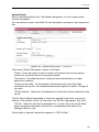
Configuration
Click on the Configuration tab. The following card is displayed :
Figure 2.41 - Configuration card of the Info Channel window
The card has three sections:
"Status" : Informs whether the info channel is off (✖) or activated (✓). Activation
and deactivation are carried out on the Playlist Management card, as it will be
explained on page 53. If the channel is active, both the origin of the list which is
being played and its name are displayed.
"Output" : Through dropdown lists and slide icons you set here the RF parameters
of the info channel : frequency, level and modulation depth of the video carrier,
television system, carrier level ratio and audio modulation index ("volume"). RF
level, modulation depth and volume must be set with the help of a field strength
meter connected to the output of the unit (or of the ClassA headend). The sound
may be temporarily silenced by checking the MUTE box.
"Playlist" : You enter here the duration in seconds that you want to state as predetermined for the slides that will make up the lists.
Once you have filled in the three sections, click on the Send button. If, at the last moment, you decide to keep the
previous configuration, click on Cancel.
49
Info Channel
Creating a Playlist
Click on the Create Playlist tab. The following card appears. It has, on principle, a
unique section, "General Parameters" :
Figure 2.42 - Create Playlist card — General Parameters
The section has 3 fields :
"Name" : Enter the name you want to assign to the playlist that you are going to
create.
"Description" : Describe the playlist using the name entered above or a wider
expression if desired.
"Duration of the slide" : It is the duration that will have all the slides that will
make up the playlist. The predetermined duration appears by defect. Change it
if you want.
Click next on the Send button. The new playlist is saved in the HMS-130 unit and
at the same time two new sections come out in the window: "Slides of the Playlist"
and "Sound" :
"Slides of the Playlist" : This section has 2 fields (see Figure 2.43 on the next page)
with a collection of icons which do very easy to make up the playlist that you are
creating.
"Playlist" : The box is on principle empty. The slides to be incorporated may be
brought either from the box at right ("Slides available"), where all the slides
stored in the HMS-130 unit are shown, or from a local storage unit (i.e. hard
disk). In the first case, one select the desired files in the box at right and then
click on the
icon between the two box. In the second cas (transfer from a
local unit), click on the last icon from above (
) and select the files as
usual.
Once all the desired image files (slides) are in the left box, you can preview and
order them by using the icons from above :
50
Info Channel
Figure 2.43 - Create Playlist card — Slides of the list
- Previews the selected slide.
- Erases the selected slide.
- Put in the first place the selected slide.
- Steps up one position the selected slide.
- Steps down one position the selected slide.
- Puts in the last place the selected slide.
- Exchanges the positions of two selected slides.
- Puts in alphabetical order the slides visible in the box.
- Allows to add slides from a local storage unit.
51
Info Channel
"Slides available" : The rest of jpg and bmp image files stored in the HMS-130
are shown in this box. The two icons from above have the following functions:
- Previews the selected slide.
- Puts in alphabetical order the slides of the box.
"Sound" : You select here the mp3 file to incorporate to the playlist that you are
creating. The file will be one which is stored either in the HMS-130 unit or in a local
storage unit.
This section has 4 fields that are empty on principle, with the exception of the third
one ("New sound file") :
"Current sound" : It is the mp3 file that have been selected through the third or
fourth field.
"Erase sound" : If you decide to erase the current sound, check the box and
click on the Send button
"New sound file" : Here you can either select directly one of the mp3 files stored
in the HMS-130 unit or direct the selection towards a local storage unit (i.e. hard
disk) by choosing "Upload new sound file" from the dropdown list. Once the file
is selected, click on the Send button. If you selected a file stored in the HMS130 unit, its name will appear now in the "Current sound" field.
"Upload new sound file" : This field is only enabled if you chose "Upload new
sound file" in the previous field. Select the mp3 file in the local storage unit and
click on the Send button. The name of the file will appear now in the "Current
sound" field.
Once the composition of the new playlist is completed, click on the Send button.
The "Slides of the Playlist" and "Sound" sections disappear, and the window starts
showing only the "General Parameters" section.
52
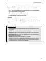
Info Channel
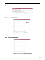
Managing Playlists
Click on the Manage Playlists tab. The related card appears showing a table with the
characteristics of all the playlist stored in the HMS-130 and, eventually, those of a
playlist stored in a pendrive which would be plugged in the unit. The table has 4 icons,
two at the left and two at the right :
- Allows to edit the name of the selected playlist.
- Removes the selected playlist.
- Activates the selected playlist, if it was stopped. (If a playlist is activated when
other playlist is active, the latter is automatically stopped before the former
become active).
- Stops the active playlist. (All the time only one playlist may be active).
USING AN USB PENDRIVE. When a pendrive which has several jpg or bmp image
files and one mp3 sound file in its root folder is plugged in the USB port of the HMS-130
unit, this one just creates, based on these files, a playlist that becomes automatically
the active playlist. The slides will be displayed on the TV set screen taking an
alphabetical order.
The playlist created from an USB pendrive will appear in the table together with the rest
of playlists, but the related icons are different : edit and remove icons are not available
but a new one (
), which allows to export to the HMS-130 unit the image and sound
files contained in the pendrive.
Figure 2.44 - Manage Playlists card of the Info Channel window
53
Info Channel
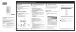
Upload Playlist
Click on the Upload Playlist tab. The related card appears. It has a unique section :
"Playlist Parameters".
This card allows to store in the HMS-130 unit the playlists contained in zip compressed
files.
Figure 2.45 - Upload Playlist card — Local ZIP
The unique, "Playlist Parameters" section has 5 fields :
"Name" : Enter the name you want to assign to the playlist that you are going to
create from the zip file that you are going to upload.
"Description" : Describe the playlist using the name entered above or a wider
expression if desired.
"Duration of the slide" : It is the duration that will have each one of the slides
contained in the zip file. The predetermined duration appears by defect. Change it if
you want.
"ZIP file location" : Select from the dropdown list the location (local or external) of the
zip file.
The fifth field is different depending on what was selected in the fourth one: local or
external. If the location is local (i.e. hard disk), the "ZIP file" field appears (Fig. 2.45) :
"ZIP file" : Select the file from the dropdown list, as usual. Then click on the Send
button: the playlist contained in the zip file is incorporated to the table of the
"Manage Playlists" card.
If the location is external, the field that appears is "ZIP File Path" :
54
Info Channel
"ZIP File Path" : The file will be in a http or ftp server. Type the complete URL
address. Then click on the Send button. The new playlist is incorporated to the table
of the "Manage Playlists" card.
Figure 2.46 - Upload Playlist card — External ZIP
55
Info Channel
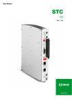
Playlist Scheduler
The purpose of playlist schedules is to broadcast —on preset time and date and with
preset duration— chosen playlists among those stored in the HMS-130 unit.
Click on the Scheduler tab. The related card appears :
Figure 2.47 - Scheduler card of the Info Channel window
The process of creating playlist schedules is similar to that explained por OSD
schedules (page 40). On the left-hand menu of the general program screen, click on
the Headend ➝ Scheduler. The Scheduler window is displayed :
Figure 2.48 - Playlist Scheduler (I-a)
The Settings card of this window shows the schedules currently stored in the HMS unit.
In the figure, none exist yet. To create a schedule of a playlist, click on "Create new
schedule". A form is displayed in the same area of the window (see Fig. 2.49 on the
next page):
56
Info Channel
Figure 2.49 - Playlist Scheduler (I-b)
Fill in the two fields existing in the Configuration and Module form:
"Configuration type": Select Playlist from the dropdown list.
"Configuration name": Select the name of the desired playlist for scheduling.
Next, fill in the Start section :
Start "Date" and "Time": Enter the date and time as of which the playlist will be
broadcasted.
"No repeat" / "Repeat": Refers to not endow or endow with periodicity the
broadcasting of the playlist.
Fill in the Duration section :
"Days", "Hours" and "Minutes" : Enter the desired duration of the playlist.
Finally, fill in the Repeat Pattern:
(Note : This section does not appear if you selected "No repeat" above)
"Repeat": The frequency with which the playlist appears.
Once you have completed all of the sections, click on Send. The form disappears and
the window displays the list of existing schedules (as Module's as OSD's as Playlist's),
which will include the one that you have just created (see Fig. 2.29 on page 42).
57
Chapter Three - Submitting Reports
In this Chapter
●
Alarms log
●
Traffic in the IKUSUP Bus
●
HMS Internal Temperature
●
GSM Signal Reception Level
●
System Logs
58
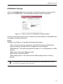
Reports
Alarms log
Figure 3.1 - Alarms Log window
Traffic in the IKUSUP Bus
Figure 3.2 - Traffic in the IKUSUP Bus window
HMS Internal Temperature
Figure 3.3 - HMS Internal Temperature window
59
Reports
GSM Signal Reception Level
Figure 3.4 - GSM Signal Reception Level window
System Logs
Figure 3.5 - System Logs window
60
IKUSI - Ángel Iglesias, S.A.
Paseo Miramón, 170
20009 San Sebastián
SPAIN
Tel.: +34 943 44 88 00
Fax: +34 943 44 88 11
www.ikusi.com
ER-0149/1996