1
Panasonic Telephone Systems
Panasonic KX-TA1232
www.voicesonic.com
Phone: 877-289-2829
A1232
ADVANCED
HYBRID SYSTEM
KX-TA1232
Advanced Hybrid System
Panasonic
Programming Guide
Panasonic KX-TA1232, KXTA1232, TA1232, KX-TA123260, KX-TA123270, KX-TA123280, KX-TA123291, KX-TA123293, KX-T77, KX-T73
Please read this manual before using the Advanced Hybrid System.
Introduction
Introduction
About this Programming Guide
This Programming Guide is designed to serve as an overall system programming reference for
the Panasonic Advanced Hybrid System, KX-TA1232.
This manual contains the following sections:
Section 1, General Programming Instructions
Provides information about what you need or what you should do before/during programming.
Section 2, General Programming
Provides details about the general system programmings.
Section 3, Default Values
Provides the list of default values for all programmings.
Section 4, Index
Provides the important words and phrases to help you access the required information easily.
About the other manuals
Along with this Programming Guide, the following manuals are available to help you install,
know the available features and use the KX-TA1232 system:
Installation Manual
Provides instructions for installing the hardware and optional equipment.
Features Guide
Provides information about the system features.
User Manual
Provides operating instructions for the end users using proprietary telephones, single line
telephones, consoles.
2
Programming Guide
Table of Contents
Table of Contents
1
1.1
1.2
1.3
1.4
1.5
1.6
2
General Programming Instructions ................................................7
General Programming Instructions .............................................................................8
Using Proprietary Telephones.......................................................................................9
Programming Methods ................................................................................................12
Entering Characters.....................................................................................................14
User Programming Mode ............................................................................................16
Programming Example................................................................................................17
General Programming ....................................................................19
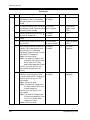
2.1 Manager Programming ...............................................................................................20
[000] Date and Time Set ......................................................................................................20
[001] System Speed Dialing Number Set ............................................................................22
[003] Extension Number Set ................................................................................................24
[004] Extension Name Set....................................................................................................26
[005] Flexible CO Button Assignment.................................................................................27
[006] Operator / Manager Extension Assignment................................................................29
[007] DSS Console Port and Paired Telephone Assignment ...............................................31
[008] Absent Messages ........................................................................................................33
[009] Quick Dial Number Set ..............................................................................................35
[014] VM Name Set .............................................................................................................36
[017] DISA User Codes .......................................................................................................37
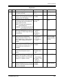
2.2 System Programming...................................................................................................39
[100] Flexible Numbering ....................................................................................................39
[101] Day / Night Service Switching Mode.........................................................................43
[102] Day / Night Service Starting Time .............................................................................44
[103] Automatic Access Outside Line Assignment .............................................................46
[105] Account Codes............................................................................................................47
[106] Station Hunting Type..................................................................................................49
[107] System Password ........................................................................................................51
[108] Automatic Hold by CO / DSS Button ........................................................................52
[109] Expansion Unit Type ..................................................................................................53
[110] Caller ID Code Set......................................................................................................54
[111] Caller ID Name Set.....................................................................................................56
[113] VM Status DTMF Set.................................................................................................57
[114] VM Command DTMF Set ..........................................................................................59
[116] ROM Version Display ................................................................................................61
[117] Voice Mail Number Assignment ................................................................................62
[118] Voice Mail Extension Number Assignment ...............................................................63
[119] Voice Mail Extension Group Assignment..................................................................65
[120] User Password ............................................................................................................66
[121] Walking COS Password .............................................................................................68
[124] Phantom Extension Number Assignment...................................................................69
[125] Area Code Assignment ...............................................................................................71
[126] Caller ID Modification for Local Call ........................................................................72
[127] Caller ID Modification for Long Distance Call..........................................................74
[150] Lunch Service Starting / Ending Time .......................................................................75
Programming Guide
3
Table of Contents
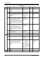
[151] Break Service Starting / Ending Time ....................................................................... 77
2.3 Timer Programming ................................................................................................... 79
[200] Hold Recall Time....................................................................................................... 79
[201] Transfer Recall Time ................................................................................................. 80
[202] Call Forwarding — No Answer Time ....................................................................... 81
[203] Intercept Time............................................................................................................ 82
[204] Pickup Dial Waiting Time ......................................................................................... 83
[205] Extension-to-Outside Line Call Duration Time......................................................... 84
[206] Outside-to-Outside Line Call Duration Time ............................................................ 85
[207] First Digit Time ......................................................................................................... 86
[208] Inter Digit Time ......................................................................................................... 87
[211] Dial Start Time........................................................................................................... 88
[212] Call Duration Count Start Time................................................................................. 89
[213] DISA Delayed Answer Time ..................................................................................... 90
[214] DISA Prolong Time ................................................................................................... 91
[215] Outgoing Message Time ............................................................................................ 92
[216] Message Waiting Ring Interval Time ........................................................................ 94
[217] Timed Reminder Alarm Ring Time........................................................................... 95
[218] DISA AA Wait Time ................................................................................................. 96
[219] Call Park Recall Time................................................................................................ 97
[221] Caller ID Call Waiting Time ..................................................................................... 98
2.4 TRS Programming ...................................................................................................... 99
[300] TRS Override for System Speed Dialing................................................................... 99
[301-305] TRS Denied Code Entry for Levels 2 through 6 .............................................. 100
[306-310] TRS Excepted Code Entry for Levels 2 through 6........................................... 102
[311] Special Carrier Access Codes .................................................................................. 104
[332] Extra Entry Table Selection ..................................................................................... 105
[333] TRS Entry Code Assignment for Extra Table ......................................................... 106
[334] Emergency Dial Number Set ................................................................................... 107
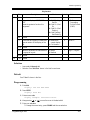
2.5 Outside Line Programming ...................................................................................... 108
[400] Outside Line Connection Assignment ..................................................................... 108
[401] Outside Line Group Assignment ............................................................................. 109
[402] Dial Mode Selection ................................................................................................ 111
[403] Pulse Speed Selection .............................................................................................. 113
[404] DTMF Time ............................................................................................................. 114
[405] CPC Signal Detection Incoming Set........................................................................ 115
[406] Caller ID Assignment .............................................................................................. 116
[407-408] DIL 1:1 Extension —— Day / Night ............................................................... 117
[409-410] Intercept Extension —— Day / Night .............................................................. 119
[411] Host PBX Access Codes.......................................................................................... 121
[412] Pause Time............................................................................................................... 123
[413] Flash Time ............................................................................................................... 124
[414] Disconnect Time ...................................................................................................... 126
[415] CPC Signal Detection Outgoing Set ........................................................................ 127
[417] Outside Line Name Assignment .............................................................................. 129
[440] Line Hunting Sequence............................................................................................ 131
[457-458] DIL 1:1 — Lunch / Break Group ..................................................................... 132
[462] Caller ID Call Waiting Assignment......................................................................... 134
[463-464] DIL 1:1 Extension —— Lunch / Break ........................................................... 135
4
Programming Guide
Table of Contents
2.6 COS Programming.....................................................................................................137
[500]-[501] Toll Restriction Level —— Day / Night ........................................................137
[502] Extension-to-Outside Line Call Duration Limit .......................................................139
[503] Call Transfer to Outside Line ...................................................................................141
[504] Call Forwarding to Outside Line ..............................................................................142
[505] Executive Busy Override..........................................................................................143
[506] Executive Busy Override Deny ................................................................................144
[507] Do Not Disturb Override ..........................................................................................145
[508] Account Code Entry Mode .......................................................................................146
[510] Night Service Access................................................................................................148
[511] PT Programming Level ............................................................................................149
2.7 Extension Programming ............................................................................................151
[601] Class of Service ........................................................................................................151
[602] Extension Group Assignment ...................................................................................153
[603-604] DIL 1:N Extension and Delayed Ringing —— Day / Night ............................155
[605-606] Outgoing Permitted Outside Line Assignment —— Day / Night ....................157
[607-608] Doorphone Ringing Assignment —— Day / Night ..........................................159
[609] Voice Mail Access Codes.........................................................................................160
[610] Live Call Screening Recording Mode Assignment ..................................................162
[619] Extension Call Forwarding — No Answer Time .....................................................163
[620] Lunch / Break Group Assignment ............................................................................164
[621] Cordless PT Extension Port ......................................................................................165
[624] Common Area Call Log Check Assignment ............................................................167
[625] Room Monitor Assignment ......................................................................................168
2.8 Resource Programming .............................................................................................169
[800] SMDR Incoming / Outgoing Call Log Printout .......................................................169
[801] SMDR Format ..........................................................................................................171
[802] System Data Printout ................................................................................................172
[803] Music Source Use .....................................................................................................174
[804] External Pager BGM ................................................................................................175
[805] External Pager Confirmation Tone...........................................................................176
[806] Serial Interface (RS-232C) Parameters ....................................................................177
[809] DISA Security Type .................................................................................................179
[810] DISA Tone Detection ...............................................................................................180
[812] DISA DTMF Repeat.................................................................................................181
[813] Floating Number Assignment...................................................................................182
[815] DISA Built-in Auto Attendant..................................................................................184
[818] Doorphone Ringing / Tone Pattern Selection...........................................................185
[819] Doorphone Access Tone Selection...........................................................................187
[820] Doorphone Ringing Time .........................................................................................188
[821] Doorphone Ring/Chime Selection............................................................................189
[822] Doorphone Chime Assignment ................................................................................191
[823] Doorphone Chime Pattern Selection ........................................................................192
2.9 Optional Programming..............................................................................................194
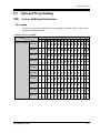
[990] System Additional Information ................................................................................194
[991] COS Additional Information ....................................................................................204
3
Default Values................................................................................209
Programming Guide
5
Table of Contents
4
6
Index............................................................................................... 219
Programming Guide
General Programming Instructions
Section 1
General Programming Instructions
Programming Guide
7
General Programming Instructions
1.1
General Programming Instructions
Default Setting
This system has a default factory setting. If any of the programming needs to be changed, you
will find the necessary information in the Features Guide. This makes the system very simple
to install and customize as required by the customer. Any required changes can be written in
"Programming Tables".
Required Telephone Set
One of the following telephone sets with display is required for System Programming:
• Proprietary Telephone (PT):
KX-T7135, KX-T7130, KX-T7030
Extensions Used for Programming
Connect one of the above-mentioned telephone sets to either of the following:
• Jack number 1
• Jack programmed as a manager extension
To assign the manager extension, see Section 2.1 Manager Programming [006]
Manager Extension Assignment.
Operator /
User Programming (Manager Programming)
Manager programming items are allowed for any display proprietary telephone user in the
system. See Section 1.5 User Programming Mode.
8
Programming Guide
General Programming Instructions
1.2
Using Proprietary Telephones
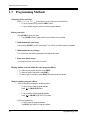
Using the Overlay
A programming overlay is packed with the telephone at the factory. This overlay should be
used at all times while in programming mode since the functions of the telephone keys change
while in programming mode as follows: (The original functions are in parentheses.)
During Normal Operation
During Programming
(PAUSE)
PAUSE
(SP-PHONE)
NEXT
(REDIAL)
PREV (PREVIOUS)
(AUTO ANSWER / MUTE)
SELECT
(FLASH)
FLASH
(TRANSFER)
CLEAR
(FWD/DND)
(CONF)
–/
(INTERCOM)
SECRET
(AUTO DIAL / STORE)
STORE
(HOLD)
END
Programming Guide
9
General Programming Instructions
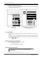
Location of Controls with the Overlay
The pictures below show the functions of the buttons of the KX-T7135, KX-T7130, and KXT7030 while in programming mode.
–/
SECRET
PREV
FLASH
SECRET – /
CLEAR
CLEAR
PAUSE
PAUSE
STORE
STORE
AUTO
SELECT
AUTO
SELECT
END
NEXT
KX-T7030
PREV
FLASH
END
NEXT
KX-T7130 / KX-T7135
Viewing the Display
The display gives you helpful information, such as what you should do now, what you have
done, etc.
The KX-T7135, KX-T7130, and the KX-T7030 utilize one information line for programming.
The display capacity is 16 digits. If your entry exceeds the capacity, you can shift the display
by pressing
or
button.
Before entering the programming mode
Before entering programming mode, confirm that:
• Your telephone is on-hook.
• No calls are on hold at your telephone.
Entering the programming mode
Press PAUSE + + # and enter your System Password
(default=1234).
• The display shows the Initial Message: SYS-PGM NO?
10
Programming Guide
General Programming Instructions
Note
• If nothing is entered in five seconds after the PAUSE button is pressed, it is canceled.
• The System Password entered is not shown on the display. The System Password can be
changed by System Programming. Refer to Section [107] System Password.
• During the programming mode, your extension is treated as a busy extension.
• Only one proprietary telephone can be in programming mode at any one time.
Programming Guide
11
General Programming Instructions
1.3
Programming Methods
Advancing to the next stage
When "SYS-PGM NO? " is displayed, you can select one of the following:
• To go to program [000], press the NEXT button.
• To go to another program, enter the 3-digit program address.
Storing your data
Press STORE to store your data.
• The STORE indicator lights red and a confirmation tone is emitted.
* Confirmation tone (one beep)
After pressing STORE, you will hear a beep. This informs you that storage is completed.
* Confirmation tone (two beeps)
This informs the user that the parameter has already been stored.
* Alarm tone (three beeps)
If you hear this alarm, your entry is not valid.
Making another selection within the same program address
• To make the next higher selection, press NEXT.
• To make the previous selection, press PREV.
• To make a specific selection, press SELECT and then enter the number.
Going to another program address
a) While displaying the program address and title:
• To go to the next larger program address:
Press
or MESSAGE button.
• To go to the next smaller program address:
Press
or SECRET (INTERCOM) button.
b) While programming:
• To go to a specific program address:
Press END, then enter the Program Address.
12
Programming Guide
General Programming Instructions
Note
The following programming instructions assume that you have already entered the
programming mode and that you will use Method (b).
Confirming the entries
You may review the stored programming without making any changes.
Going back to the operation mode
Two ways are available to go back to the operation mode:
a) Lift the handset while in programming mode.
b) When the Initial Message: SYS-PGM NO? is displayed, press the PAUSE button. (To
display the Initial Message, press END.)
Programming Guide
13
General Programming Instructions
1.4
Entering Characters
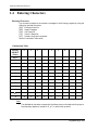
Entering Characters
You can enter characters to store names or messages in the following programs by using the
dialing key pad and the buttons.
[004] Extension Name Set
[008] Absent Messages
[014] VM Name Set
[111] Caller ID Name Set
[417] Outside Line Name Assignment
See the Combination Table below.
Combination Table
Pressing
SELECT
(Times)
0
1
2
3
4
5
6
1
1
Q
q
Z
z
!
?
2
2
A
a
B
b
C
c
3
3
D
d
E
e
F
f
4
4
G
g
H
h
I
i
5
5
J
j
K
k
L
l
6
6
M
m
N
n
O
o
7
7
P
p
Q
q
R
r
8
8
T
t
U
u
V
v
9
9
W
w
X
x
Y
y
0
0
.
,
’
:
;
7
8
S
s
Z
z
Keys
#
*
/
+
-
=
<
>
#
$
%
&
@
(
)
Note
• The alphabetical characters correspond to the letters shown on the twelve dialing keys on
the proprietary telephone. (except for Q, q, Z, z and all other symbols)
14
Programming Guide
General Programming Instructions
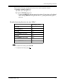
Please see the following example which shows how to select a desired character.
For example, to select the letter "M":
a) Press 6. ("M" belongs to "6".)
b) Press the SELECT button once.
• Pressing the SELECT button an appropriate number of times gives you the desired
letter. Pressing SELECT twice gives the letter "m", pressing three times gives "N",
and so on.
Example of entering characters: to enter "Mike":
The display shows:
1. Enter 6.
6
2. Press SELECT.
M
3. Enter 4.
M4
4. Press SELECT six times.
Mi
5. Enter 5.
Mi5
6. Press SELECT four times.
Mik
7. Enter 3.
Mik3
8. Press SELECT four times.
Mike
Note
• To erase all the letters, press CLEAR.
• To erase the last letter, press
Programming Guide
.
15
General Programming Instructions
1.5
User Programming Mode
User Programming Mode
Some programming items are accessible by any display proprietary telephone user in the
system.
The programming items are listed below:
[000] Date and Time Set
[001] System Speed Dialing Number Set
[003] Extension Number Set
[004] Extension Name Set
[005] Flexible CO Button Assignment
[006] Operator / Manager Extension Assignment
[007] DSS Console Port and Paired Telephone Assignment
[008] Absent Messages
[009] Quick Dial Number Set
[014] VM Name Set
[017] DISA User Codes
Entering the user programming mode
You can access these programs by entering the User Programming Mode as follows:
Before entering the mode, confirm that:
• Your telephone is on-hook.
• No calls are on hold at your telephone
Press PAUSE +
(default: 1234)
+
and enter the User Password
After entering the mode, perform the same programming steps as the system programming
steps in each program address.
Note
• If nothing is entered in five seconds after the PAUSE button is pressed, it is canceled.
• The User Password is not shown on the display. The password can be changed by system
programming. Refer to Section [120] User Password.
• During the programming mode, your extension is treated as a busy extension.
• Only one proprietary telephone can be in programming mode at any one time.
16
Programming Guide
General Programming Instructions
1.6
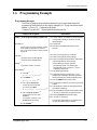
Programming Example
Programming Example
The following programming instructions assume that you have already entered the
programming mode and that you will employ method (b) of "Going to another program
address" in Section 1.3 Programming Methods.
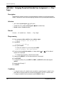
Example: Program [001] System Speed Dialing Number Set.
Sample of Description
Explanation
(2)
[001] (1) System Speed Dialing Number Set
Description (3)
Used to program the System Speed Dial numbers.
These numbers are available to all extension
users. There are 500 numbers available from 000
through 499.
Selection
(4) Shows you choices that you can assign.
(5) Shows you the default (factory setting).
(6) Shows you programming procedures step by step.
• While programming, use the overlay.
• Before starting to program, enter the
programming mode. (See "Entering the
programming mode" in section 1.2 "Using
Proprietary Telephones".)
(7) Enter the program address.
(8) The display shows the program title. If your
telephone has soft buttons, the lower line shows
the functions that are currently assigned to them.
(9) Press the NEXT shown on the overlay.
(4)
• Speed dial number: 000 through 499
• Telephone number: 24 digits (max.)
Default
(5)
All speed dial numbers - Not stored
Programming
(6)
(7)
1. Enter 001.
Display: 001 SYS SPD DIAL
2. Press NEXT.
(8)
(9)
Display: SPD Code?→
(10)
3. Enter a speed dial number.
To enter speed dial number 000,
you can also press NEXT.
Display example: 000:Not Stored
4. Enter a telephone number. (12)
To delete the current entry, press
CLEAR.(13)
To change the current entry, press
CLEAR and the new number.
5. Press STORE.
Programming Guide
(14)
(1) Program address: This address is printed at the top
of every page to allow you to quickly find the
desired program.
(2) Program title.
(3) Provides a more detailed description of the
program.
(11)
(10) The message line advises you to enter a speed dial
number.
(11) If the telephone number has already been stored,
the number is displayed.
(12) Enter the telephone number that you want to store.
Your entry is displayed as you enter the digits.
(13) Pressing CLEAR erases the whole entry.
(14) Your entry is now stored.
The indicator lights red and a confirmation tone
lets you know that storage is complete.
17
General Programming Instructions
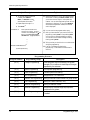
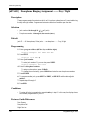
Sample of Description
Explanation
6. To program another speed dial
number, press NEXT or
PREV, or SELECT and the
desired speed dial number. (15)
(15) Select the best way for you to store another speed
dial number. Pressing the NEXT / PREV allows
you to select the next higher / lower speed dial
number. You can also keep pressing them until the
desired one is displayed. If you press SELECT
and the desired speed dial number, the selected
code is displayed.
7. Repeat steps 4 through 6. (16)
8. Press END. (17)
Conditions
(18)
• Each speed dial number has a
maximum of 24 digits. The valid
characters are 0 through 9, the and
# keys, and the FLASH, PAUSE,
SECRET and – (hyphen) buttons.
(16) You can continue to program another entry.
(17) After you have stored all your entries, finish this
program by pressing END. After pressing END
you can go to any program address you desire.
You can return to the Initial Message mode any
time by pressing END.
(18) Tells you what you should notice or consider when
doing the programming.
(19) Lists all of the features related to the
programming. These features are described in
Section 3.
(19)
Features Guide References
System Speed Dialing
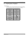
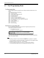
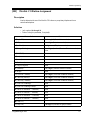
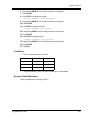
Programming Structure
Program Address
18
Programming Group
Description
[0XX]
Manager Programming
These programs may be accessed by the system
manager of the customer to meet frequent changes
requested by the customer.
[1XX]
System Programming
Entire system programming.
[2XX]
Timer Programming
Flexible system timer setting.
[3XX]
TRS Programming
Assignment of Toll Restriction.
[4XX]
Outside Line Programming
Setting of outside line and outside line group values.
[5XX]
COS Programming
Setting of Class of Service (COS).
[6XX]
Extension Programming
Setting of extension values.
[8XX]
Resource Programming
Assignment of customer-supplied peripherals
connected to the system.
[9XX]
Option Programming
Used to answer the user's requirements or troubles,
if needed.
Programming Guide
General Programming
Section 2
General Programming
Programming Guide
19
General Programming
2.1
Manager Programming
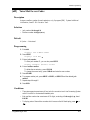
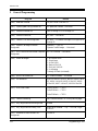
[000] Date and Time Set
Description
Sets the current date and time. A 12 hour format or 24 hour format can be selected.
Selection
•
•
•
•
•
•
•
•
Year: 00 through 99
Month: Jan. through Dec.
Day: 1 through 31
Day of the week: SUN / MON / TUE / WED / THU / FRI / SAT
Hour: 1 through 12
Minute: 00 through 59
AM / PM
Hour format: 12 or 24
Default
'01 Jan. 1 MON 12:00 AM 12
Programming
1. Enter 000.
Display: 000 DATE / TIME
2. Press NEXT.
Display example: '01 Jan. 1 MON 12:00 AM 12
3. Enter the year.
To change the current entry, press CLEAR and enter the new year.
4. Press
.
5. Keep pressing SELECT until the desired month is displayed.
6. Press
.
7. Enter the day.
To change the current entry, press CLEAR and enter the new day.
8. Press
.
9. Keep pressing SELECT until the desired day of the week is displayed.
10.Press STORE.
11.Press NEXT.
Display example: 12:00 PM 24
20
Programming Guide
General Programming
12.Enter the hour.
To change the current entry, press CLEAR and enter the new hour.
13.Press
.
14.Enter the minute.
To change the current entry, press CLEAR and enter the new minute.
15.Press
.
16.Press SELECT for AM or PM.
17.Press
.
18.Press SELECT for 12 or 24 (hour format).
19.Press STORE.
20.Press END.
Conditions
• After changing an entry, you can press STORE. You do not have to perform the rest of the
steps.
•
•
•
•
•
To return to a previous field, press
in steps 4 through 9 and steps 13 through 18.
If you hear an alarm after pressing STORE, check that the date is valid.
The clock starts immediately after the STORE button is pressed.
You cannot leave an entry empty.
Program [990] System Additional Information, Area 05 - Bit 1 is used to enable the
automatic time adjustment by Caller ID information once a day.
Features Guide References
Display, in Idle
Programming Guide
21
General Programming
[001] System Speed Dialing Number Set
Description
Used to program the System Speed Dial numbers. These numbers are available to all extension
users. There are 500 numbers available from 000 to 499.
Selection
• Speed dial number: 000 through 499
• Telephone number: 24 digits (max.)
Default
All speed dial numbers - Not stored
Programming
1. Enter 001.
Display: 001 SYS SPD DIAL
2. Press NEXT.
Display: SPD Code?
3. Enter a speed dial number.
To enter speed dial number 000, you can also press NEXT.
Display example: 000:Not Stored
4. Enter a telephone number.
To delete the current entry, press CLEAR.
To change the current entry, press CLEAR and enter the new number.
5. Press STORE.
6. To program another speed dial number, press NEXT or PREV, or SELECT and the
desired speed dial number.
7. Repeat steps 4 through 6.
8. Press END.
Conditions
• Each speed dial number has a maximum of 24 digits. The valid characters are 0 through 9,
the and # keys, and the FLASH, PAUSE, SECRET and — (hyphen) buttons.
-To store a flash signal, press FLASH.
Note:
The stored flash will only be effective during a call. (Refer to Section "External Feature
Access" in the Features Guide.)
-To store a hyphen, press the "—" button.
22
Programming Guide
General Programming
•
•
•
•
-To store a pause, press PAUSE. (Refer to Section "Pause Insertion, Automatic" in the
Features Guide.)
-To store a feature number to convert pulse signals to DTMF (Dual Tone Multi-Frequency)
signals, press the and # keys. (Refer to Section "Pulse to Tone Conversion" in the
Features Guide.)
-To prevent displaying of all or part of the number, press SECRET before and after the
secret number, or your entry will not be stored. (Refer to Section "Secret Dialing" in the
Features Guide.)
If you are storing an external number, include the line access code (default: 9, 81 through
88) before the number. When dialing, a pause is automatically inserted after the code.
If you are storing an account code, enter the account code before the line access code. (Refer
to Section "Account Code Entry" in the Features Guide.)
A number consisting of 25 digits or more can be stored by storing it in two speed dial
numbers. The line access code should be stored in the first speed dial number.
To access another speed dial number in steps 3 through 6, press SELECT and start with
step 3.
• To display parts of the number which have scrolled off the display, press
or
.
Features Guide References
System Speed Dialing
Programming Guide
23
General Programming
[003] Extension Number Set
Description
Assigns an extension number to each extension.
Note
This programming should be performed before you connect a Panasonic Voice Processing
System (VPS) because the VPS can create mailboxes automatically based on your extension
plan (extension number set).
Selection
• Jack number: 01 through 32
• Extension Number: 2 through 4 digits
Default
Jack 01 through 32 = 101 through 132
Programming
1. Enter 003.
Display: 003 EXT NUMBER
2. Press NEXT.
Display: Jack NO?
3. Enter a jack number.
To enter jack number 01, you can also press NEXT.
Display: #01:EXT101
4. Enter an extension number.
To change the current entry, press CLEAR and enter the new number.
5. Press STORE.
6. To program another jack, press NEXT or PREV, or SELECT and the desired jack
number.
7. Repeat steps 4 through 6.
8. Press END.
Conditions
• There is a maximum of 32 extension numbers. Each extension number can be two, three, or
four digits, consisting of 0 through 9. The and # keys cannot be used.
• An extension number is invalid if the first or second digits do not match with the program
"[100] Flexible Numbering, (01) - (16) 1st through 16th hundred extension blocks"
setting. If one digit is assigned as the leading digit, some extensions have two digits and
24
Programming Guide
General Programming
some have three digits. If two digits are assigned, some have three digits and some have
four digits.
• A double entry or incompatible entry is invalid including the program [118] Voice Mail
Extension Number Assignment, [124] Phantom Extension Number Assignment,
[813] Floating Number Assignment. Valid entry examples are: 10 and 11; 10 and 110.
Invalid entry example is: 10 and 106.
• Program [004] Extension Name Set is used to name the extension numbers.
Features Guide References
Display, Call Information
Flexible Numbering
Intercom Calling
Programming Guide
25
General Programming
[004] Extension Name Set
Description
Assigns names to the extension numbers programmed in program [003]
Set.
Extension Number
Selection
• Jack number: 01 through 32
• Name: 10 characters (max.)
Default
All jacks — Not stored
Programming
1. Enter 004.
Display: 004 EXT NAME SET
2. Press NEXT.
Display: Jack NO?
3. Enter a jack number.
To enter jack number 01, you can also press NEXT.
Display: #01:Not Stored
4. Enter a name.
For entering characters, see Section 1.4 Entering Characters.
To delete the current entry, press CLEAR.
To change the current entry, press CLEAR and enter the new name.
5. Press STORE.
6. To program another jack, press NEXT or PREV, or SELECT and the desired jack
number.
7. Repeat steps 4 through 6.
8. Press END.
Conditions
• There is a maximum of 32 names. Each name has a maximum of 10 characters.
• Program [003] Extension Number Set is used to assign extension numbers.
Features Guide References
Display, Call Information
Intercom Calling
26
Programming Guide
General Programming
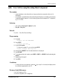
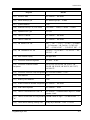
[005]
Flexible CO Button Assignment
Description
Used to determine the use of the flexible CO buttons on proprietary telephones from a
centralized telephone.
Selection
• Jack number: 01 through 32
• Button Code (plus parameter, if required):
Button Code
Parameter
0 (Single-CO)
01 through 12 (Outside line number)
1 (DSS)
2 to 4 digits (Extension number)
2 (One-Touch)
16 digits max. (Telephone number)
3 (Message Waiting)
2 to 4 digits (Another / Phantom Extension number) or
None
4 (FWD/DND)
None
5 (Save)
None
6 (Account)
None
70 (Conference)
None
71 (Log-In/Log-Out)
None
72 (Phantom)
2 to 4 digits (Phantom extension number)
73 (Night)
None
8 (Voice Mail Transfer)
2 to 4 digits (Voice Mail Extension number)
90 (Two-Way Record)*
2 to 4 digits (Voice Mail Extension number)
91 (Two-Way Transfer)*
2 to 4 digits (Voice Mail Extension number)
92 (Live Call Screening)*
None
93 (Live Call Screening Cancel)*
None
94 (Caller ID Indication — Personal)
None
95 (Caller ID Selection — Personal)
None
96 (Caller ID Indication — Common)
None
97 (Caller ID Selection — Common)
None
(Loop-CO)
# (Group-CO)
Programming Guide
None
1 through 8 (Outside line group number)
27
General Programming
* Available when the KX-TA1232 is connected to a Proprietary Telephone capable Panasonic Voice
Processing System (one that supports DPT Integration; e.g., KX-TVS50).
Default
All jacks — CO buttons 1 through 12 = Single-CO 01 through 12
Programming
1. Enter 005.
Display: 005 FLEXIBLE CO
2. Press NEXT.
Display: Jack NO?
3. Enter a jack number.
To enter jack number 01, you can also press NEXT.
Display: PT—PGM Mode
4. Press the CO button which is changed to another button.
The display shows the contents pre-assigned to the button.
Display example: CO-01
5. Enter a button code (plus parameter, if required).
To change the parameter, press CLEAR and enter the new parameter.
6. Press STORE.
7. To program another CO button of the same jack, repeat steps 4 through 6.
To program another jack, press SELECT and repeat steps 3 through 6.
8. Press END.
Canceling
1. Perform the same procedures as steps 1 through 4 above.
2. Enter 2.
3. Press STORE.
4. Press END.
Conditions
• A centralized telephone is a telephone connected to jack 01 or a jack programmed as a
manager extension in program [006] Operator / Manager Extension Assignment.
Features Guide References
Button, Flexible
Buttons on Proprietary Telephones
28
Programming Guide
General Programming
[006]
Operator / Manager Extension Assignment
Description
Assigns the jack number for a manager and/or operators. The manager extension can perform
System Programming and manager services. The operators have the ability to perform operator
services.
Selection
• OPE-1 (operator 1) / OPE-2 (operator 2) / MNGER (manager)
• Jack number: 01 through 32
Default
Operator 1 — Jack 01;
Operator 2 and Manager — Not stored
Programming
1. Enter 006.
Display: 006 OP-1, 2, MGR
2. Press NEXT to program operator 1.
Display: OPE-1:Jack01
To program another item, you can also keep pressing NEXT or PREV until the desired
one is displayed.
3. Enter a jack number.
To assign no operator or manager, press CLEAR.
To change the current entry, press CLEAR and enter the new jack number.
4.
5.
6.
7.
Press STORE.
To program another item, press NEXT or PREV.
Repeat steps 3 through 5.
Press END.
Conditions
• Up to two operators and a manager can be programmed.
• The manager cannot be assigned the jack number of the DSS Console Port set in program
[007] "DSS Console Port and Paired Telephone Assignment".
• If there is no operator or manager, press CLEAR in step 3.
Features Guide References
Manager Extension
Programming Guide
29
General Programming
Operator
30
Programming Guide
General Programming
[007]
DSS Console Port and Paired Telephone Assignment
Description
Assigns the jack numbers for the DSS Console and the paired extension.
Selection
• DSS Console number: 1 through 4
• Jack number for DSS Console: 02 through 32
• Jack number for paired extension: 01 through 32
Default
All DSS Consoles — Not stored
Programming
1. Enter 007.
Display: 007 DSS CONSOLE
2. Press NEXT.
Display: DSS NO?
3. Enter a DSS Console number.
To enter DSS Console number 1, you can also press NEXT.
Display example: DSS—1:# P:#
4. Enter a jack number for the console.
To delete the current entry, press CLEAR.
To change the current entry, press CLEAR and enter the new jack number.
5. Press
.
6. Enter a jack number for the paired extension.
To change the current entry, press CLEAR and enter the new jack number.
Display example: DSS—1:#02 P:#03
7. Press STORE.
8. To program another DSS Console, press NEXT or PREV, or SELECT and the desired
DSS Console number.
9. Repeat steps 4 through 8.
10.Press END.
Conditions
• The jack number for the Console and that for the paired extension must be entered together.
• Multiple DSS Consoles cannot be assigned to the same DSS Console jack.
Programming Guide
31
General Programming
• Multiple DSS Consoles can be paired with the same proprietary telephone jack.
• A DSS Console jack cannot be assigned the jack 01 and the jack number of Manager set in
program [006] Operator / Manager Extension Assignment.
• If all incoming outside calls are set to ring at the operator extension telephone in program
[407-408] DIL 1:1 Extension —— Day / Night, assigning a DSS Console to the operator
extension makes the operator's job much easier.
• If a single line telephone is assigned as the pair extension, the paired DSS Console will not
function.
Features Guide References
DSS Console
32
Programming Guide
General Programming
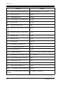
[008]
Absent Messages
Description
Used to program the absent messages. An absent message, if set by the station user, is
displayed on the calling extension's telephone to show the reason for the user's absence.
Selection
• Message number: 1 through 9
• Message: 16 characters (max.)
Default
1: Will Return Soon
2: Gone Home
3: At Ext %%%
4: Back at %%:%%
5: Out Until %%/%%
6: In a Meeting
7 through 9: Blank (not stored)
Programming
1. Enter 008.
Display: 008 ABSENT MSG.
2. Press NEXT.
Display: MSG NO?
3. Enter a message number.
To enter message number 1, you can also press NEXT.
Display example: MSG1:Will Return
4. Enter the message.
For entering characters, see Section 1.4 Entering Characters.
To delete the current entry, press CLEAR.
To change the current entry, press CLEAR and enter the new message.
5. Press STORE.
6. To program another message, press NEXT or PREV, or SELECT and the desired message
number.
7. Repeat steps 4 through 6.
8. Press END.
Programming Guide
33
General Programming
Conditions
• There is a maximum of nine messages. Messages 1 through 6 are programmed at the factory
but can be changed. Each message has a maximum of 16 characters.
• You can enter a maximum of seven "%" characters per message which can be programmed
at each user's extension. The station user can enter 0 through 9, and # for the %
characters. If the user enters digits less than the number of "%" characters, it is
recommended to fill the remaining "%" characters with "#" or " ".
• If there are 4-digit extension numbers available in your system, add one "%" to Message 3.
• To display parts of the message which have scrolled off the display, press
or
.
Features Guide References
Absent Message Capability
34
Programming Guide
General Programming
[009]
Quick Dial Number Set
Description
Stores up to eight quick dial numbers.
Selection
• Location number: 1 through 8
• Desired number: 16 digits (max.)
Default
All location numbers — Not stored
Programming
1. Enter 009.
Display: 009 QUICK DIAL
2. Press NEXT.
Display: Location NO?
3. Enter a location number.
To enter location number 1, you can also press NEXT.
Display example: 1:Not Stored
4. Enter a desired number.
To delete the current entry, press CLEAR.
To change the current entry, press CLEAR and enter the new number.
5. Press STORE.
6. To program another location, press NEXT or PREV, or SELECT and the desired location
number.
7. Repeat steps 4 through 6.
8. Press END.
Conditions
• A maximum of sixteen digits, consisting of 0 through 9, can be assigned to a quick dial
number.
• Before programming, assign a feature number for each location first in program
[100] Flexible Numbering.
Features Guide References
Quick Dialing
Programming Guide
35
General Programming
[014] VM Name Set
Description
Assigns a name for each voice mail port.
Selection
• Voice Mail (VM) number: 01 through 08
• Name: 10 characters (max.)
Default
VM01: V.Mail 01, VM02: V.Mail 02, VM03: V.Mail 03, VM04: V.Mail 04, VM05: V.Mail
05, VM06: V.Mail 06, VM07: V.Mail 07, VM08: V.Mail 08
Programming
1. Enter 014.
Display: 014 VM PORT NAME
2. Press NEXT.
Display: VM NO?
3. Enter a VM number.
To enter VM number 01, you can also press NEXT.
Display example: VM01:V.Mail 01
4. Enter a name.
For entering characters, see Section 1.4 Entering Characters.
To delete the current entry, press CLEAR.
To change the current entry, press CLEAR and enter the new name.
Display example: VM01:Voice No.1
5. Press STORE.
6. To program another voice mail port, press NEXT or PREV, or SELECT and the desired
voice mail number.
7. Repeat steps 4 through 6.
8. Press END.
Conditions
None
Features Guide References
Voice Mail Integration
36
Programming Guide
General Programming
[017]
DISA User Codes
Description
Assigns the Direct Inward System Access (DISA) User Codes and a Class of Service (COS) to
each code. The COS of the code determines the toll restriction level of the DISA caller.
Note
Warning for the Direct Inward System Access Users
When you enable the Outside – Outside Line Call feature of Direct Inward System Access
(DISA) function, if a third party discovers the password (a DISA User Code) of the system,
you have a risk that they will make illegal phone calls using your telephone line, and the cost
may be charged to your account.
In order to avoid this problem, we strongly recommend the following points:
1. Carefully maintain the secrecy of the password.
2. Specify a complicated password as long and random as you can make it.
3. Change the password frequently.
Selection
• DISA user code number: 01 through 32
• DISA user code: 4 through 10 digits
• COS number: 1 through 8
Default
Code 01=Blank — COS 8
Code 02=Blank — COS 8
:
Code 32=Blank — COS 8
Programming
1. Enter 017.
Display: 017 USER CODES
2. Press NEXT.
Display: User Code NO?
3. Enter a DISA user code number.
To enter user code number 01, you can also press NEXT.
Display example: 01:
C:8
4. Enter a DISA user code.
To change the current entry, enter the new code.
Programming Guide
37
General Programming
5. Press
to program COS.
6. Enter a COS number.
To change the current entry, enter the new COS number.
7. Press STORE.
8. To program another user code, press NEXT or PREV, or SELECT and the desired DISA
user code number.
9. Repeat steps 4 through 8.
10.Press END.
Conditions
• This setting is required if Trunk (Outside line) Security mode is selected in program
[809] DISA Security Type.
• There are 32 programmable user codes. Each code should be unique and composed of four
through ten numerical digits, 0 through 9.
Features Guide References
Direct Inward System Access (DISA)
38
Programming Guide
General Programming
2.2
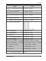
[100]
System Programming
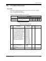
Flexible Numbering
Description
Assigns the leading digits of extension numbers and feature numbers for system features.
Feature Number List
Number
Feature
Default
01
1st hundred extension block
1
02
2nd hundred extension block
2
03 - 16
3rd through 16th hundred extension block
None
17
Operator call
0
18
Automatic line access
9
19
Outside line group line access
8
20
System speed dialing
21
Personal speed dialing
3
22
Personal speed dialing programming
30
23
Doorphone call
31
24
Paging — external
32
25
Paging — external answer / TAFAS answer
42
26
Paging — group
33
27
Paging — group answer
43
28
Call pickup, outside line
4
29
Call pickup, group
40
30
Call pickup, directed
41
31
Call hold
50
32
Call hold retrieve — intercom
51
33
Call hold retrieve — outside line
53
34
Last number redial
#
35
Call park / call park retrieve
52
36
Account code entry
49
37
Door opener
55
Programming Guide
39
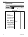
General Programming
Feature Number List
Number
40
Feature
Default
38
External feature access
6
39
Station program clear
790
40
Message waiting
70
41
Outgoing message
36
42
Call forwarding / do not disturb
710
43
Call pickup deny
720
44
Data line security
730
45
Call waiting
731
46
Executive busy override deny
733
47
Pickup dialing
74
48
Absent message
750
49
Timed reminder
76
50
Electronic station lockout
77
51
Day / Lunch / Break / Night service mode
78
52
Parallel telephone mode
39
53
Background music — external
35
54
LCS password
799
55
Call log, incoming
56
56
Call log lock, incoming
57
57
Timed reminder, remote
7
58
Log-in / log-out
45
59
Automatic callback busy cancel
46
60
Walking COS
47
61
Reserved
–
62
System working report
794
63 - 70
Quick dial location numbers 1-8
None
71 - 89
Reserved
None
90
Paging — deny
721
91
Reserved
92
Call log, clear
590
93
Room Monitor
734
–
Programming Guide
General Programming
Selection
• Selection number:
01 through 93 (See "Feature Number List" for the corresponding features.)
• Feature number:
1 or 2 digits (for selection numbers 01 – 16);
1 through 3 digits (for selection numbers 17 – 60, 62 – 70, 90 and 92 – 93)
Default
See "Feature Number List" on the previous pages.
Programming
1. Enter 100.
Display: 100 FLEX. NUMBER
2. Press NEXT.
Display: Select NO?
3. Enter a selection number.
To enter selection number 01, you can also press NEXT.
Display example: 01. 1-EXT BL:1
4. Enter the feature number.
To delete the feature number, press CLEAR.
To change the current entry, press CLEAR and enter the new number.
5. Press STORE.
6. To program another selection, press NEXT or PREV, or SELECT and the desired
selection number.
7. Repeat steps 4 through 6.
8. Press END.
To remove all the feature numbers except selection numbers (01) through (16) 1st
through 16th extension blocks;
1. Enter 100.
2. Press NEXT.
3. Enter 00.
Display: All Feature CLR?
4. Press STORE.
5. Press END.
Conditions
• Each extension block has one or two digits, consisting of 0 through 9. Assign the leading
digits for extension numbers of the respective blocks.
Programming Guide
41
General Programming
• Assignment of extension blocks defines the limits for programs [003] Extension Number
Set, [118] Voice Mail Extension Number Assignment, [124] Phantom Extension
Number Assignment and [813] Floating Number Assignment.
• Each feature number has one through three digits, consisting of 0 through 9,
, and #.
• If or # is included in a feature number, dial pulse telephone users cannot access the
feature.
• Double entry and incompatible combinations are invalid. Valid entry examples: 30 and 31,
210 and 211. Invalid entry examples: 5 and 5, 30 and 301.
• If you delete a feature number, the feature cannot be used by dialing operation.
• You can remove all the feature numbers except selections (01) through (16).
• To clear an extension block (01) through (16), it is required to change the corresponding
numbers assigned in program [003] Extension Number Set, [118] Voice Mail
Extension Number Assignment, [124] Phantom Extension Number Assignment and
program [813] Floating Number Assignment.
Features Guide References
Flexible Numbering
42
Programming Guide
General Programming
[101]
Day / Night Service Switching Mode
Description
This program is used to determine if night mode is set automatically or manually.
Selection
Manual / Auto (automatic)
Default
Manual
Programming
1. Enter 101.
Display: 101 DAY/NT AUTO
2. Press NEXT.
Display example: D/N Mode:Manual
3. Keep pressing SELECT until the desired selection is displayed.
4. Press STORE.
5. Press END.
Conditions
• If automatic switching is assigned, day / night mode is switched at the time programmed in
[102] Day / Night Service Starting Time.
• The operator and manager can switch the day / night mode at any time.
Features Guide References
Night Service
Programming Guide
43
General Programming
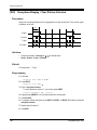
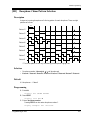
[102] Day / Night Service Starting Time
Description
Sets the starting time on a day of the week basis, when automatic day / night switching is
programmed in program [101] Day / Night Service Switching Mode.
Selection
• Day of the week selection number:
1 (Sunday) / 2 (Monday) /3 (Tuesday) / 4 (Wednesday) /
5 (Thursday) / 6 (Friday) / 7 (Saturday) / (every day of the week)
• Hour: 1 through 12 / Disable (no switching)
• Minute: 0 through 59
• AM / PM
Default
Every day of the week — Day — 9:00 AM / Night — 5:00 PM
Programming
1. Enter 102.
Display: 102 DAY/NT CLOCK
2. Press NEXT.
Display: Day of Week?
3. Enter the day of the week selection number.
To select Sunday, you can also press NEXT.
Display example: Sun-Day:9:00 AM
To select night mode, press NEXT.
Display example: Sun-Nt :5:00 PM
4. Enter the hour.
To set no switching, keep pressing SELECT until "Disable" is displayed and go to step
9.
If SELECT is pressed, the display shows the previous entry. If the previous setting was
"Disable", press SELECT to enter the starting time.
To change the current entry, press CLEAR and enter the new time.
5. Press
.
6. Enter the minute.
To change the current entry, press CLEAR and enter the new minutes.
7. Press
.
8. Press SELECT for AM or PM.
9. Press STORE.
44
Programming Guide
General Programming
10.To program another day / night mode or day of the week, press NEXT or PREV, or
SELECT and the day of the week selection number.
11.Repeat steps 4 through 10.
12.Press END.
Conditions
• To select the desired day, you may keep pressing NEXT in step 3. To assign every day of
the week to one selection, press the key in step 3. In this case, the display shows the
contents programmed for Sunday.
• If day / night switching is not desired, select "Disable" in step 4.
• You cannot leave the entry empty.
Features Guide References
Night Service
Programming Guide
45
General Programming
[103] Automatic Access Outside Line Assignment
Description
Assigns the sequence in which outside line groups will be accessed when in Automatic Line
Access mode. When a user dials the feature number for automatic line access (default=9) or
presses the Loop-CO button, an idle line is searched for in the programmed outside line group
order.
Selection
• Outside line group number: 1 through 8 in desired order
Default
12345678
Programming
1. Enter 103.
Display: 103 AUTO CO GRP
2. Press NEXT.
Display example: Access:12345678
3. Enter the outside line group numbers in priority from top to bottom.
To delete the current entry, press CLEAR.
To change the current entry, press CLEAR and enter the new order.
4. Press STORE.
5. Press END.
Conditions
• The system supports a maximum of eight outside line groups.
Features Guide References
Line Access, Automatic
Line Access, Direct
Line Preference — Outgoing (Idle Line / No Line / Prime Line)
46
Programming Guide
General Programming
[105]
Account Codes
Description
Assigns the account codes for Account Code Entry, Verified — All Calls and Verified — Toll
Restriction Override modes. If Verified — All Calls is assigned in program [508] Account
Code Entry Mode, an account code is required to make an outside call. If Verified — Toll
Restriction Override is assigned, an account code is only required for a toll call and overrides
toll restriction.
Selection
• Location number: 001 through 128
• Account code: 10 digits (max.)
Default
All locations — Not stored
Programming
1. Enter 105.
Display: 105 ACCT CODES
2. Press NEXT.
Display: Location NO?
3. Enter a location number.
To enter location number 001, you can also press NEXT.
Display example: 001:Not Stored
4. Enter an account code.
To delete the current entry, press CLEAR.
To change the current entry, press CLEAR and enter the new account code.
5. Press STORE.
6. To program another location, press NEXT or PREV, or SELECT and the desired location
number.
7. Repeat steps 4 through 6.
8. Press END.
Conditions
• Each verifiable account code has a maximum of 10 digits, consisting of 0 through 9.
• Program [508] Account Code Entry Mode is used to select the Account Code Entry mode.
• Account codes having "99" in any part or ending with "9" are invalid, as "99" is used as a
delimiter when entering an account code.
Programming Guide
47
General Programming
Features Guide References
Account Code Entry
Toll Restriction Override by Account Code Entry
48
Programming Guide
General Programming
[106]
Station Hunting Type
Description
Used to enable or disable hunting and set the Station Hunting type for each extension group.
There are five Station Hunting types available: Circular, Terminating, Voice Mail (VM),
Automated Attendant (AA), Ring Group.
If circular hunting is assigned for a group, all of the extensions in the group are searched until
an idle one is found. If terminating hunting is assigned, searching stops at the extension which
has the largest jack number in the group. If VM hunting is assigned, all of the VM ports of an
extension group are searched until an idle one is found which allows Voice Mail Service. If
AA hunting is assigned, all of the AA ports of an extension group are searched until an idle one
is found which allows AA Service. If Ring Group is assigned, all of the extensions in the ring
group ring simultaneously.
Selection
• Extension group number: 1 through 8,
( = all extension groups)
• Disable (no hunting) / Terminate (terminating) / Circular / VM (voice mail) / AA
(automated attendant) / RING
Default
All extension groups — Disable
Programming
1. Enter 106.
Display: 106 STATION HUNT
2. Press NEXT.
Display: EXT GRP NO?
3. Enter an extension group number.
To enter extension group number 1, you can also press NEXT.
Display example: Group1:Disable
4. Keep pressing SELECT until the desired selection is displayed.
5. Press STORE.
6. To program another extension group, press NEXT or PREV, or SELECT and the desired
extension group number.
7. Repeat steps 4 through 6.
8. Press END.
Programming Guide
49
General Programming
Conditions
• Program [602]
members.
Extension Group Assignment is used to assign the extension group
• To assign all extension groups to one selection, press the key in step 3. In this case, the
display shows the contents programmed for extension group 1.
Features Guide References
Ring Group
Station Hunting
Voice Mail Integration
50
Programming Guide
General Programming
[107]
System Password
Description
Assigns the password required for entering System Programming mode.
Selection
Password: 4 through 7 digits
Default
1234
Programming
1. Enter 107.
Display: 107 SYS PASSWORD
2. Press NEXT.
Display: Password:1234
3. Enter a password.
To change the current entry, press CLEAR and enter the new password.
4. Press STORE.
5. Press END.
Conditions
• The password can be from four to seven digits long. The valid numbers are from 0 through
9.
• If less than four digits are entered, they are not stored.
• You cannot leave the entry empty.
Features Guide References
System Programming with Proprietary Telephone
Programming Guide
51
General Programming
[108] Automatic Hold by CO / DSS Button
Description
Enables or disables automatically holding an outside call when a DSS (Direct Station
Selection) button on the DSS Console or proprietary telephone, or a CO button on a proprietary
telephone is pressed. Through this assignment, each button acts as follows:
—— Pressing the DSS button holds an outside call and quickly transfers it to an extension
without pressing the TRANSFER button.
—— Pressing another CO button holds the current outside call.
Selection
• Button: DSS or CO
• Enable / Disable
Default
DSS button — Enable, CO button — Disable
Programming
1. Enter 108.
Display: 108 AUTO HOLD
2. Press NEXT to program the DSS button.
Display example: DSS XFER:Enable
3. Keep pressing SELECT until the desired selection is displayed.
4. Press NEXT to program the CO button.
Display example: CO Hold:Disable
5. Keep pressing SELECT until the desired selection is displayed.
6. Press STORE.
7. Press END.
Conditions
• This assignment applies to all DSS and CO buttons on all DSS Consoles and proprietary
telephones in the system.
Features Guide References
Automatic Hold by CO Button
One-Touch Transfer by DSS Button
52
Programming Guide
General Programming
[109]
Expansion Unit Type
Description
Assigns the type of expansion units to be used in the system.
This allows the system to identify the unit in each expansion unit location.
Selection
• Areas 1; 2; 3 = C / E1 / E2
(C: 4-Outside lines, E1: 8-Extension lines 1 /
E2: 8-Extension lines 2)
Default
C;E1;E2
Programming
1. Enter 109.
Display: 109 EXPAND C, E1
2. Press NEXT.
Display example: C ;E1;E2
3. Keep pressing SELECT until the desired selection in Area 1 is displayed.
4.
5.
6.
7.
Press
to program another Area, if required.
Keep pressing SELECT until the desired selection in the Area is displayed.
Repeat steps 4 and 5 until all the required entries are completed.
Press END.
Conditions
• The following units can be installed in the slots.
— C (4-Outside lines): 4 CO Line Expansion Unit
— E1, E2 (8-Extension lines):
8 Extension Expansion Unit
• There are three expansion areas in each system for the KX-TA1232, areas 1, 2 and 3 from
bottom to top. Up to two 8 Extension Expansion Units and one of 4 CO Line Expansion
Unit can be installed.
• After changing the setting, turn the Power Switch off and on once. Otherwise, the previous
setting will remain.
Features Guide References
Module Expansion
Programming Guide
53
General Programming
[110] Caller ID Code Set
Description
Sets the identification code of the calling party (Caller ID Code) to utilize a Caller ID Service
provided by a specific central office (CO). If an ID Code transmitted from the CO is found in
the Caller ID Code Table, the caller's ID Code or name given to the code in program
[111] Caller ID Name Set is displayed on the telephone. This allows the called party to
recognize the caller.
Selection
• Location number: 001 through 500
• Caller ID Code: 24 digits (max.)
Default
All locations — Not stored
Programming
1. Enter 110.
Display: 110 CALLER ID #
2. Press NEXT.
Display: Location NO?
3. Enter a location number.
To enter location number 001, you can also press NEXT.
Display example: 001:Not Stored
4. Enter a Caller ID Code.
To delete the current entry, press CLEAR.
To change the current entry, press CLEAR and enter the new code.
5. Press STORE.
6. To program another location, press NEXT or PREV, or SELECT and the desired location
number.
7. Repeat steps 4 through 6.
8. Press END.
Conditions
• Each Caller ID Code has a maximum of 24 digits, consisting of 0 through 9.
• Program [111] Caller ID Name Set is used to give names to the Caller ID Codes. If an ID
Code is assigned a name, the called party's telephone will show the name in place of the ID
Code.
54
Programming Guide
General Programming
• Program [406]
line basis.
Caller ID Assignment is used to enable the Caller ID Service on an outside
Features Guide References
Caller ID
Programming Guide
55
General Programming
[111] Caller ID Name Set
Description
With Caller ID Service, the calling party is displayed either by its ID Code or by its name. If
the name display is required, use this program to give a name to a caller ID Code stored in
program [110] Caller ID Code Set.
Selection
• Location number: 001 through 500
• Caller ID Name: 15 characters (max.)
Default
All locations — Not stored
Programming
1. Enter 111.
Display: 111 CALLER NAME
2. Press NEXT.
Display: Location NO?
3. Enter a location number.
To enter location number 001, you can also press NEXT.
Display example: 001:Not Stored
4. Enter a Caller ID Name.
For entering characters, see Section 1.4 Entering Characters.
To delete the current entry, press CLEAR.
To change the current entry, press CLEAR and enter the new name.
5. Press STORE.
6. To program another location, press NEXT or PREV, or SELECT and the desired location
number.
7. Repeat steps 4 through 6.
8. Press END.
Conditions
• Caller ID Name corresponds to the Caller ID Codes stored in program [110]
Code Set.
• Each name has a maximum of 15 characters.
56
Caller ID
Programming Guide
General Programming
Features Guide References
Caller ID
Programming Guide
57
General Programming
[113] VM Status DTMF Set
Description
Sets the DTMF (Dual Tone Multi-Frequency) signals transmitted to your Voice Processing
System (VPS) to inform the VPS of the VPS ports states quickly:
The following signals are sent to the VPS with the assigned DTMF signals:
RBT (ringback tone):
This signal is sent when calling an extension.
BT (busy tone):
This is sent when the called extension is busy.
ROT (reorder tone):
This is sent when the dialed number is invalid.
DND (DND tone):
This is sent when the other extension has DND assigned.
Answer:
This is sent when the other extension answers the call.
Disconnect:
This is sent when the other extension hangs up.
Confirm (confirmation tone) :
This is sent when the feature number for "Message Waiting Lamp" is valid.
FWD VM RBT (FWD to VM ringback tone) :
Not available (reserved).
FWD VM BT (FWD to VM busy tone) :
This is sent when the called extension has set Call Forwarding to VPS.
FWD EXT RBT (FWD to extension ringback tone) :
Not available (reserved).
Selection
• RBT / BT / ROT / DND / Answer / Disconnect / Confirm / FWD VM RBT / FWD VM
BT / FWD EXT RBT
• DTMF signal number: 3 digits (max.)
Default
RBT — 1; BT — 2; ROT — 3; DND — 4; Answer — 5; Disconnect — #9; Confirm —9; FWD
VM RBT — 6; FWD VM BT — 7; FWD EXT RBT — 8
Programming
1. Enter 113.
Display: 113 VM DTMF SET
2. Press NEXT to program ringback tone status.
To program another status, keep pressing NEXT until the desired status is displayed.
58
Programming Guide
General Programming
Display example: RBT :1
3. Enter a DTMF signal number.
To delete the current entry, press CLEAR.
To change the current entry, press CLEAR and enter the new number.
4. Press STORE.
5. To program another selection, keep pressing NEXT or PREV until the desired selection is
displayed.
6. Repeat steps 3 through 5.
7. Press END.
Conditions
• A DTMF signal number can have a maximum of three digits, consisting of 0 through 9, ,
# and PAUSE.
• The DTMF signals are sent to the extensions in the extension group that is assigned as
"VM" or "AA" in program [106] Station Hunting Type.
Features Guide References
Voice Mail Integration
Programming Guide
59
General Programming
[114] VM Command DTMF Set
Description
Sets the DTMF (Dual Tone Multi-Frequency) command signals transmitted to your Voice
Processing System (VPS). There are four commands available: Leave Message; Get Message;
Automated Attendant Service; Voice Mail Service. These commands are used in the following
ways:
(A) If your VPS is used for Voice Mail (VM) Service
(1) Call Forwarding / Intercept Routing to Voice Mail
If a call is forwarded to the VPS, your system will send a mailbox number to the VM port. This
allows the caller to leave a message without knowing the mailbox number.
• Required entries (selections):
LV-MSG (Leave Message): This command is transmitted to a VM port if a call is
forwarded or intercepted and rerouted to the port.
AA-SVC (Automated Attendant Service): If "Disable" is selected in program [990],
Area 05 - Bit 7, the "AA-SVC" command is sent to a VM port when an incoming outside
call is routed to the VM port by IRNA.
• Other programming required (program addresses): [106]; [602]; [609]; [990], Area 02 Bit 8
(2) Hearing the message at the extension
If the VPS receives a message and lights the MESSAGE button indicator of the dialed
telephone, the telephone user can hear the message by pressing the MESSAGE button.
• Required entries (selections):
GETMSG (Get Message): This command is transmitted to a VM port when the message
receiver presses the MESSAGE button.
VM-SVC (Voice Mail Service): The "VM-SVC" command is a code transmitted
preceding the "GETMSG" command above.
This is effective to switch to VM port when an AA port lights the MESSAGE indicator.
• Other programming required (program addresses): [609]; [990], Area 02 - Bit 8
(B) If your VPS is used for Automated Attendant (AA) Service
An AA port answers an incoming outside call to provide AA services, such as call transfer,
receiving a message.
• Required entries (selections):
VM-SVC (Voice Mail Service): The "VM-SVC" command is a code transmitted before
the "LV-MSG" code if an operator transfers a call to an extension and then it is
forwarded to an AA port so that the AA port can be switched to the VM port temporarily.
• Other programming required (program addresses): [106], [602]
Selection
• LV-MSG / GETMSG / AA-SVC / VM-SVC
• DTMF signal number: 16 digits (max.)
60
Programming Guide
General Programming
Default
LV-MSG — H; GETMSG — *H; AA-SVC — #8 ; VM-SVC — #6
Programming
1. Enter 114.
Display: 114 VM DTMF CMD
2. Press NEXT to program the LV-MSG command.
To program another command, keep pressing NEXT until the desired command is
displayed.
Display example: LV-MSG:H
3. Enter a DTMF signal number.
To delete the current entry, press CLEAR.
To change the current entry, press CLEAR and enter the new number.
4. Press STORE.
5. To program another selection, keep pressing NEXT or PREV until the desired selection is
displayed.
6. Repeat steps 3 through 5.
7. Press END.
Conditions
• A command signal number can have a maximum of 16 digits, consisting of 0 through 9,
, # , FLASH and PAUSE.
• The FLASH button is available only for LV-MSG and GETMSG commands to store "H"
which means "Home Position".
• If "H" is stored for "LV-MSG", a mailbox number programmed in program [609] Voice
Mail Access Codes or an extension number will be sent to the VM port (Follow On ID
function). If certain codes are required before and after the ID code, insert "H" between the
codes, as "aaaHbbb". If nothing is stored, it will operate as "H".
• If " H" is stored for "GETMSG", a mailbox number programmed in program
[609] Voice Mail Access Codes or an extension number will be sent to the port
succeeding the " ".
Features Guide References
Voice Mail Integration
Programming Guide
61
General Programming
[116] ROM Version Display
Description
Confirms the version of ROM of the system.
Display example:
Y831AA30101A
Version
Date
Selection
None
Default
Not applicable.
Programming
1. Enter 116.
Display: 116 ROM VERSION
2. Press NEXT.
The display shows the ROM version.
3. Press END.
Conditions
None
Features Guide References
None
62
Programming Guide
General Programming
[117]
Voice Mail Number Assignment
Description
Four KX-TA1232 jacks (listed below) are available for connection to a Panasonic Voice
Processing System (VPS) with DPT Integration capability. Each jack supports two DPT VPS
ports. This program assigns the jack numbers corresponding to VPS ports.
Selection
• Jack number: 07, 08, 15, 16
Default
All jacks — Blank
Programming
1. Enter 117.
Display: 117 VMS PORT ASN
2. Press NEXT to program.
Display example: # # # #
3. Enter a jack number.
To delete the current entry, press CLEAR.
To change the current entry, press CLEAR and enter the new jack number.
4.
5.
6.
7.
Press
to enter another jack number.
Repeat steps 3 through 4 to enter another jack number.
Press STORE.
Press END.
Conditions
• Only jack number 07, 08, 15 or 16 is assigned as a voice mail port jack.
• The jack numbers correspond to the voice mail port in numerical order.
Example: Stored jack numbers: Jacks 07, 08, 15, 16
Jack 07=Voice mail numbers 01, 02; Jack 08=Voice mail numbers 03, 04;
Jack 15=Voice mail numbers 05, 06; Jack 16=Voice mail numbers 07, 08
• This program is for DPT Integration only. Do not use it for Inband Integration.
Features Guide References
Voice Mail Integration (DPT Integration)
Programming Guide
63
General Programming
[118] Voice Mail Extension Number Assignment
Description
Assigns the extension number for the voice mail number. These numbers can be used the same
way extension numbers are used for station access.
Selection
• Voice mail number (VM): 01 through 08
• Extension Number: 2 to 4 digits
Default
VM-01=165, VM-02=166, VM-03=167, VM-04=168, VM-05=169, VM-06=170, VM07=171, VM-08=172
Programming
1. Enter 118.
Display: 118 VM EXT #
2. Press NEXT.
Display: VM NO?
3. Enter a voice mail number.
To enter voice mail number 01, you can also press NEXT.
Display: VM-01:#07-1:165
4. Enter an extension number.
To change the current entry, press CLEAR and enter the new number.
5. Press STORE.
6. To program another voice mail number, press NEXT or PREV, or SELECT and the
desired voice mail number.
7. Repeat steps 4 through 6.
8. Press END.
Conditions
• You cannot leave an entry empty.
• Double entry and incompatible entry for these numbers are invalid. Valid entry example:
10 and 11, 10 and 110. Invalid entry example: 10 and 106.
To avoid making an invalid entry, check the other extension numbers in programs
[003] Extension Number Set, [124] Phantom Extension Number Assignment and
[813] Floating Number Assignment.
64
Programming Guide
General Programming
• The display shows "VM-XX:#YY:ZZZ" in step 3. "XX" means the voice mail number.
"YY" means the jack number of the voice mail port programmed in [117] Voice Mail
Number Assignment. "ZZZ" represents the voice mail extension number.
Features Guide References
Voice Mail Integration (DPT Integration)
Programming Guide
65
General Programming
[119] Voice Mail Extension Group Assignment
Description
Assigns each voice mail number to a voice mail extension group number.
Selection
• Voice mail number (VM): 01 through 08, ( =all voice mail numbers)
• Voice mail extension group number (EXG) = 1 through 8
Default
All voice mail numbers — EXG 1
Programming
1. Enter 119.
Display: 119 VM EXT GROUP
2. Press NEXT.
Display: VM NO?
3. Enter a voice mail number.
To enter voice mail number 01, you can also press NEXT.
Display example: VM-01:#07-1:EXG1
4. Enter the voice mail extension group number.
To delete the current entry, press CLEAR.
To change the current entry, enter the new number.
5. Press STORE.
6. To program another voice mail number, press NEXT or PREV, or SELECT and the
desired voice mail number.
7. Repeat steps 4 through 6.
8. Press END.
Conditions
• The display shows "VM-XX:#YY:EXG Z" in step 3.
"XX" means a voice mail number. "YY" means the jack number of the voice mail port
programmed in [117] Voice Mail Number Assignment.
• To assign all voice mail numbers to one selection, press the key in step 3. In this case,
the display shows the contents programmed for voice mail number 01.
Features Guide References
Voice Mail Integration (DPT Integration)
66
Programming Guide
General Programming
[120]
User Password
Description
Assigns the password required for entering the User Programming mode.
In the User Programming Mode, any display proprietary telephone user in the system can set
the following programs:
[000] Date and Time Set
[001] System Speed Dialing Number Set
[003] Extension Number Set
[004] Extension Name Set
[005] Flexible CO Button Assignment
[006] Operator / Manager Extension Assignment
[007] DSS Console Port and Paired Telephone Assignment
[008] Absent Messages
[009] Quick Dial Number Set
[014] VM Name Set
[017] DISA User Codes
Selection
• Password: 4 through 7 digits
Default
1234
Programming
1. Enter 120.
Display: 120 USR PASSWORD
2. Press NEXT.
Display example: Password:1234
3. Enter a password.
To change the current entry, press CLEAR and enter the new password.
4. Press STORE.
5. Press END.
Conditions
• The password can be from four to seven digits long. Valid numbers are from 0 to 9.
• If less than four digits are entered, they will not be stored.
• You cannot leave the entry empty.
Programming Guide
67
General Programming
Features Guide References
User Programming (Manager Programming)
68
Programming Guide
General Programming
[121]
Walking COS Password
Description
Assigns the password required for Walking COS.
Selection
Password: 4 through 7 digits
Default
1234
Programming
1. Enter 121.
Display: 121 COS PASSWORD
2. Press NEXT.
Display example: Password:1234
3. Enter a password.
To change the current entry, press CLEAR and enter the new password.
4. Press STORE.
5. Press END.
Conditions
• The password can be from four to seven digits long. Valid numbers are from 0 to 9.
• If less than four digits are entered, they will not be stored.
• You cannot leave the entry empty.
Features Guide References
Walking COS
Programming Guide
69
General Programming
[124] Phantom Extension Number Assignment
Description
Assigns the phantom extension numbers. Each number will be assigned to a flexible CO or
DSS (Direct Station Selection) button and used as a Phantom Extension button.
Selection
• Location number: 001 through 128
• Phantom extension number: 2 to 4 digits
Default
All locations — Not stored
Programming
1. Enter 124.
Display: 124 PHANTOM #
2. Press NEXT.
Display: Location NO?
3. Enter a location number.
To enter location number 001, you can also press NEXT.
Display example: 001:Not Stored
4. Enter a phantom number.
To delete the current entry, press CLEAR.
To change the current entry, press CLEAR and enter the new number.
5. Press STORE.
6. To program another location, press NEXT or PREV, or SELECT and the desired location
number.
7. Repeat steps 4 through 6.
8. Press END.
Conditions
• Each phantom number has two to four digits, consisting of numbers 0 through 9.
• The first one or two digits of the phantom extension numbers are subject to program
[100] Flexible Numbering, (01) through (16) 1st through 16th hundred extension blocks.
• Phantom extension numbers and other extension numbers should be unique. Double entry
and incompatible entry for these numbers are invalid. Valid entry example: 10 and 11, 10
and 110. Invalid entry example: 10 and 106.
To avoid making an invalid entry, check the other extension numbers in programs
70
Programming Guide
General Programming
[003]
[813]
Extension Number Set, [118] Voice Mail Extension Number Assignment and
Floating Number Assignment.
Features Guide References
Phantom Extension
Programming Guide
71
General Programming
[125] Area Code Assignment
Description
Assigns up to ten area codes which are necessary when using the Caller ID feature. By
assigning your area code, the system records the caller's phone number modified by programs
[126] Caller ID Modification for Local Call and [127] Caller ID Modification for Long
Distance Call.
Selection
• Location number: 01 through 10
• Area code: 1 through 6 digits
Default
All locations — Blank
Programming
1. Enter 125.
Display: 125 AREA CODE
2. Press NEXT.
Display: Location NO?
3. Enter a location number.
To enter location number 01, you can also press NEXT.
Display example: 01:
4. Enter an area code.
To change the current entry, press CLEAR and enter the new area code.
5. Press STORE.
6. To program another location number, press NEXT or PREV, or SELECT and the desired
location number.
7. Repeat steps 4 through 6.
8. Press END.
Conditions
• The area code can be six digits long. Valid numbers are from 0 to 9.
• The location numbers used in this program corresponds to those in program [126]
ID Modification for Local Call.
Caller
Features Guide References
Caller ID
72
Programming Guide
General Programming
Call Log, Incoming
Programming Guide
73
General Programming
[126] Caller ID Modification for Local Call
Description
Assigns removed digits from the received caller's number of a local call, and adds number to
make the final number which serves as the Caller ID number. The system records the modified
caller's number to the incoming call log list so that the extension user can call back the caller.
Digits are removed from or added to the beginning of the received digits.
Selection
• Location number: 01 through 10
• Number of digits to be deleted: 0 through 9 (0=no deletion)
• Number to be added: 4 digits (max.)
Default
All locations — Deleted number of digits = 3, Added number = blank
Programming
1. Enter 126.
Display: 126 CID LOCAL
2. Press NEXT.
Display: Location NO?
3. Enter a location number.
To enter location number 01, you can also press NEXT.
Display example: 01:Del3,Add
4. Enter the number of digits to be deleted.
To change the current entry, press CLEAR and enter the new number.
5. Press
to program the number to be added, if required.
6. Enter the number to be added.
To change the current entry, press CLEAR and enter the new number.
7. Press STORE.
8. To program another location number, press NEXT or PREV, or SELECT and the desired
location number.
9. Repeat steps 4 through 8.
10.Press END.
Conditions
• The added number has a maximum of 4 digits, consisting of 0 through 9,
74
and #.
Programming Guide
General Programming
• There are ten location numbers for modified numbers, which corresponds to those in
program [125] Area Code Assignment.
Features Guide References
Caller ID
Call Log, Incoming
Programming Guide
75
General Programming
[127] Caller ID Modification for Long Distance Call
Description
Assigns removed digits from the received caller's number of a long distance call, and adds
number to make the final number which serves as the Caller ID number. The system records
the modified caller's number to the incoming call log list so that the extension user can call
back the caller.
Digits are removed from or added to the beginning of the received digits.
Selection
• Number of digits to be deleted: 0 through 9 (0=no deletion)
• Number to be added: 4 digits (max.)
Default
Deleted number of digits — 0; Added number — 1
Programming
1. Enter 127.
Display: 127 CID LD
2. Press NEXT.
Display example: Del,Add:0,1
3. Enter the number of digits to be deleted.
To change the current entry, press CLEAR and enter the new number.
4. Press
to program the number to be added, if required.
5. Enter the number to be added.
To change the current entry, press CLEAR and enter the new number.
6. Press STORE.
7. Press END.
Conditions
• The added number has a maximum of 4 digits, consisting of 0 through 9,
and #.
Features Guide References
Caller ID
Call Log, Incoming
76
Programming Guide
General Programming
[150]
Lunch Service Starting / Ending Time
Description
Sets the Lunch starting and ending time for each day of the week.
Selection
• Day of the week selection number:
1 (Sunday) / 2 (Monday) / 3 (Tuesday) / 4 (Wednesday) / 5 (Thursday) / 6 (Friday) / 7
(Saturday) / (every day of the week)
• Hour: 1 through 12
• Minute: 0 through 59
• AM / PM
Default
Every day of the week – 12:00 – 12:59 PM
Programming
1. Enter 150.
Display: 150 LUNCH TIME
2. Press NEXT.
Display: Day of Week?
3. Enter the day of the week selection number.
To select Sunday, you can also press NEXT.
Display example: Sun-BGN:12:00PM
4. Enter the hour of starting time.
5. Press
.
6. Enter the minute.
To change the current entry, press CLEAR and enter the new minutes.
7. Press
.
8. Press SELECT for AM or PM.
9. Press STORE.
10.To program another lunch mode or day of the week, press NEXT or PREV, or SELECT
and the day of the week selection number.
11.Repeat steps 4 through 10.
12.Press END.
Programming Guide
77
General Programming
Conditions
• This programming can only be used if "Auto (automatic)" is selected in program
[101] Day / Night Service Switching Mode.
• Lunch service ends at the assigned time.
For example:
If Lunch service is 11:30 AM – 1:00 PM, Day mode starts at 1:01 PM.
If Lunch service is 11:30 AM – 12:59 PM, Day mode starts at 1:00 PM.
Features Guide References
Lunch / Break Service
Night Service
78
Programming Guide
General Programming
[151]
Break Service Starting / Ending Time
Description
Sets the Break starting and ending time for each day of the week.
Selection
• Day of the week selection number:
1 (Sunday) / 2 (Monday) / 3 (Tuesday) / 4 (Wednesday) / 5 (Thursday) / 6 (Friday) / 7
(Saturday) / (every day of the week)
• Hour: 1 through 12
• Minute: 0 through 59
• AM / PM
Default
Every day of the week – 3:00 – 3:29 PM
Programming
1. Enter 151.
Display: 151 BREAK TIME
2. Press NEXT.
Display: Day of Week?
3. Enter the day of the week selection number.
To select Sunday, you can also press NEXT.
Display example: Sun-BGN: 3:00PM
4. Enter the hour of starting time.
To change the current entry, press CLEAR and enter the new time.
5. Press
.
6. Enter the minute.
To change the current entry, press CLEAR and enter the new minutes.
7. Press
.
8. Press SELECT for AM or PM.
9. Press STORE.
10.To program another break mode or day of the week, press NEXT or PREV, or SELECT
and the day of the week selection number.
11.Repeat steps 4 through 10.
12.Press END.
Programming Guide
79
General Programming
Conditions
• This feature can only be used if "Auto (automatic)" is selected in program [101]
Night Service Switching Mode.
• Break service ends at the assigned time.
For example:
If Break service is 3:00 – 4:00 PM, Day mode starts at 4:01 PM.
If Break service is 3:00 – 3:59 PM, Day mode starts at 4:00 PM.
Day /
Features Guide References
Lunch / Break Service
Night Service
80
Programming Guide
General Programming
2.3
[200]
Timer Programming
Hold Recall Time
Description
Assigns the length of the hold recall timer. This timer is used to alert an extension that a call
has been held for an extended period of time.
Selection
Time (seconds): 0 through 240 (0=Hold Recall disabled)
Default
60 sec
Programming
1. Enter 200.
Display: 200 HOLD RECALL
2. Press NEXT.
Display example: Time: 60 sec
3. Enter the time.
To change the current entry, press CLEAR and enter the new time.
4. Press STORE.
5. Press END.
Conditions
• Select "0" if Hold Recall is not required.
• You cannot leave the entry empty.
Features Guide References
Hold Recall
Programming Guide
81
General Programming
[201] Transfer Recall Time
Description
Sets the number of rings before transfer recall occurs. If a transferred call is not answered after
the programmed number of rings, the call returns to the original caller.
Selection
Number of rings: 0 through 48 (0=Transfer Recall disabled)
Default
12 rings
Programming
1. Enter 201.
Display: 201 TRAN RECALL
2. Press NEXT.
Display example: Time:12 rings
3. Enter the number of rings.
To change the current entry, press CLEAR and enter the new number of rings.
4. Press STORE.
5. Press END.
Conditions
• Select "0" if Transfer Recall is not required.
• One ring is equivalent to five seconds.
• You cannot leave the entry empty.
Features Guide References
Call Transfer, Unscreened — to Extension
82
Programming Guide
General Programming
[202]
Call Forwarding — No Answer Time
Description
Sets the number of rings for Call Forwarding — No Answer feature. If a call is not answered
after the programmed number of rings, the call is forwarded to the destination.
Selection
Number of rings: 1 through 12
Default
3 rings
Programming
1. Enter 202.
Display: 202 CALL FWD-NA
2. Press NEXT.
Display example: Time: 3 rings
3. Enter the number of rings.
To change the current entry, press CLEAR and enter the new number of rings.
4. Press STORE.
5. Press END.
Conditions
• One ring is equivalent to five seconds.
• This timer is also used for Intercept Routing. If an incoming DISA (Direct Inward System
Access) call to the Intercept Routing destination is not answered before this timer expires,
the call will be disconnected.
• You cannot leave the entry empty.
Features Guide References
Call Forwarding — Busy / No Answer
Call Forwarding — No Answer
Programming Guide
83
General Programming
[203] Intercept Time
Description
Sets the number of rings for Intercept Routing — No Answer (IRNA) feature. If a call is not
answered after the programmed number of rings, the call is redirected to the programmed
station.
Selection
Number of rings: 3 through 48
Default
12 rings
Programming
1. Enter 203.
Display: 203 INTERCEPT
2. Press NEXT.
Display example: Time:12 rings
3. Enter the number of rings.
To change the current entry, press CLEAR and enter the new number of rings.
4. Press STORE.
5. Press END.
Conditions
• One ring is equivalent to five seconds.
• Programs [409-410] Intercept Extension —— Day / Night are used to program the
destination of Intercept Routing on an outside line group basis in day and night modes.
• If the original extension has set Call Forwarding — No Answer, Intercept Timer starts after
Call Forwarding.
• You cannot leave the entry empty.
Features Guide References
Intercept Routing
84
Programming Guide
General Programming
[204]
Pickup Dial Waiting Time
Description
Sets the number of seconds for Pickup Dialing. If the telephone user lifts the handset, the
programmed party is called when the time expires.
Selection
Time (seconds): 1 through 5
Default
1 sec
Programming
1. Enter 204.
Display: 204 PICKUP DIAL
2. Press NEXT.
Display example: Time:1 sec
3. Enter the time.
To change the current entry, enter the new time.
4. Press STORE.
5. Press END.
Conditions
• This time gives the user an opportunity to dial digits before the automatic dialing process
takes place.
Features Guide References
Pickup Dialing
Programming Guide
85
General Programming
[205] Extension-to-Outside Line Call Duration Time
Description
Sets the maximum time allowed for a conversation with an outside party. If an outside call is
originated or answered by a programmed extension user and the timer expires, the call is
disconnected.
Selection
Time (minutes): 1 through 64
Default
10 min
Programming
1. Enter 205.
Display: 205 EXT-CO TIME
2. Press NEXT.
Display example: Time:10 min
3. Enter the time.
To change the current entry, press CLEAR and enter the new time.
4. Press STORE.
5. Press END.
Conditions
• This time-out applies to extensions to which Limited Call Duration is assigned by program
[502] Extension-to-Outside Line Call Duration Limit.
• This time cannot be set to zero or be left empty.
Features Guide References
Limited Call Duration
86
Programming Guide
General Programming
[206]
Outside-to-Outside Line Call Duration Time
Description
Sets the maximum time allowed for a conversation between two outside parties. When the
timer expires, the Outside-to-Outside Line call is disconnected.
Selection
Time (minutes): 1 through 64
Default
10 min
Programming
1. Enter 206.
Display: 206 CO-CO TIME
2. Press NEXT.
Display example: Time:10 min
3. Enter the time.
To change the current entry, press CLEAR and enter the new time.
4. Press STORE.
5. Press END.
Conditions
• You cannot leave the entry empty.
Features Guide References
Call Forwarding — to Outside Line
Call Transfer, Screened — to Outside Line
Conference, Unattended
Direct Inward System Access (DISA)
Programming Guide
87
General Programming
[207] First Digit Time
Description
Sets the maximum time allowed between the start of an outside dial tone and the first digit
dialed on an outgoing outside call. If an extension user fails to dial any digits during this time,
the DTMF (Dual Tone Multi-Frequency) receiver is released.
Selection
Time (seconds): 5 through 120
Default
10 sec
Programming
1. Enter 207.
Display: 207 1ST DIGIT T
2. Press NEXT.
Display example: Time: 10 sec
3. Enter the time.
To change the current entry, press CLEAR and enter the new time.
4. Press STORE.
5. Press END.
Conditions
• This timer is used for toll restriction checking.
• You cannot leave the entry empty.
Features Guide References
Toll Restriction
88
Programming Guide
General Programming
[208]
Inter Digit Time
Description
Assigns the maximum time allowed between digits on an outgoing toll call. If an extension user
fails to dial any digits during this time, the DTMF (Dual Tone Multi-Frequency) receiver is
released. This timer applies until the Toll Restriction check is completed.
Selection
Time (seconds): 5 through 30
Default
10 sec
Programming
1. Enter 208.
Display: 208 INTER DIGIT
2. Press NEXT.
Display example: Time:10 sec
3. Enter the time.
To change the current entry, press CLEAR and enter the new time.
4. Press STORE.
5. Press END.
Conditions
• This timer is used for toll restriction checking.
• You cannot leave the entry empty.
Features Guide References
Toll Restriction
Programming Guide
89
General Programming
[211] Dial Start Time
Description
Sets the number of milliseconds the system waits before dialing after an outside line is seized.
Selection
Time (milliseconds): 0 through 40 ( 100 is the actual time)
Default
500 msec
Programming
1. Enter 211.
Display: 211 DIAL START
2. Press NEXT.
Display example: Time: 500 msec
3. Enter the time.
To change the current entry, press CLEAR and enter the new time.
4. Press STORE.
5. Press END.
Conditions
• You enter a number from 0 through 40. The actual time is a 100 times your input.
• You cannot leave the entry empty.
Features Guide References
Line Access, Automatic
Line Access, Direct
Line Access, Individual
Line Access, Outside Line Group
90
Programming Guide
General Programming
[212]
Call Duration Count Start Time
Description
Sets the number of seconds the system waits between the end of dialing and the start of the
Station Message Detail Recording (SMDR) timer for outgoing toll calls. When the system has
sent out all the digits to the central office and this timer expires, the system starts counting the
call. A display telephone shows the elapsed time of the call. The starting time and the duration
of a call are recorded in the SMDR record.
Selection
Time (seconds): 0 through 60
Default
0 sec
Programming
1. Enter 212.
Display: 212 CALL TIMER
2. Press NEXT.
Display example: Time: 0 sec
3. Enter the time.
To change the current entry, press CLEAR and enter the new time.
4. Press STORE.
5. Press END.
Conditions
• The timer starts counting after all the digits are dialed. This timer does not apply to
incoming calls. The timer for incoming calls starts immediately.
• You cannot leave the entry empty.
Features Guide References
Display, Call Information
Station Message Detail Recording (SMDR)
Programming Guide
91
General Programming
[213] DISA Delayed Answer Time
Description
Assigns the number of rings between a call received and the answer by the Direct Inward
System Access (DISA) feature.
Selection
Number of rings: 0 through 6
Default
1 ring
Programming
1. Enter 213.
Display: 213 DISA ANSWER
2. Press NEXT.
Display example: Time:1 rings
3. Enter the number of rings.
To change the current entry, enter the new number of rings.
4. Press STORE.
5. Press END.
Conditions
• One ring is equivalent to five seconds.
• You cannot leave the entry empty.
Features Guide References
Direct Inward System Access (DISA)
92
Programming Guide
General Programming
[214]
DISA Prolong Time
Description
Sets the maximum allowable prolonged time for an outside-to-outside line call via the Direct
Inward System Access (DISA) feature. An outside-to-outside line call is initially limited by the
"Outside-to-Outside Line Call Duration Time" (Program [206]). However, the DISA caller can
prolong the call after hearing the warning tones by pressing any key (except the key). This
parameter, the "DISA Prolong Time", sets the duration of these extended periods.
Selection
Time (minutes): 0 through 7 (0=no prolonging)
Default
3 min
Programming
1. Enter 214.
Display: 214 DISA PROLONG
2. Press NEXT.
Display example: Time:3 min
3. Enter the time.
To change the current entry, enter the new time.
4. Press STORE.
5. Press END.
Conditions
• Do not confuse this parameter with the "Outside-to-Outside Line Call Duration Time"
(Program [206]) parameter.
• Program [206] Outside-to-Outside Line Call Duration Time is used to set the duration
time allowed for an outside-to-outside line call.
• You cannot leave the entry empty.
Features Guide References
Direct Inward System Access (DISA)
Programming Guide
93
General Programming
[215] Outgoing Message Time
Description
Sets the maximum allowable recording time for outgoing messages (OGM).
Selection
Time (seconds): 0 / 16 / 32 / 64 (0=no recording)
Default
32, 0, 32, 0 (for OGM 1 through 4 from left to right)
Programming
1. Enter 215.
Display: 215 OGM MSG TIME
2. Press NEXT to program the time for OGM 1.
Display example: OGM:32, 0,32, 0
3. Keep pressing SELECT until the desired selection is displayed.
4.
5.
6.
7.
8.
Press
to program the time for OGM 2.
Keep pressing SELECT until the desired selection is displayed.
Repeat steps 4 and 5 to program the time for OGM's 3.
Press STORE.
Press END.
Conditions
• There are three messages available:
OGM 1:
used for DISA (Direct Inward System Access) message 1
OGM 2:
used for DISA message 2
OGM 3:
used for Timed Reminder
OGM 4:
not available (always set to "0")
• Enter the times starting from the left for OGM 1 to OGM 4.
• The total time of the outgoing messages cannot exceed 64 seconds.
Features Guide References
Direct Inward System Access (DISA)
94
Programming Guide
General Programming
Outgoing Message (OGM)
Timed Reminder
Programming Guide
95
General Programming
[216] Message Waiting Ring Interval Time
Description
Sets the Message Waiting ring interval time for a single line telephone.
Selection
Time (minutes): 0 through 64
Default
0 min (no ring)
Programming
1. Enter 216.
Display: 216 MW RING TIME
2. Press NEXT.
Display example: Interval: 0 min
3. Enter the time.
To change the current entry, press CLEAR and enter the new time.
4. Press STORE.
5. Press END.
Conditions
When the interval time is set to "0", the telephone does not ring for Message Waiting
notification.
Selecting the message waiting ring type, 3 quick rings or 2 normal rings, in program
[990] System Additional Information, Area 05 - Bit 11 is available. If you prefer soft ringing,
select "3 quick rings". In this case, there may be some kinds of telephones which do not ring.
Features Guide References
Message Waiting
96
Programming Guide
General Programming
[217]
Timed Reminder Alarm Ring Time
Description
Sets the number of seconds the Timed Reminder alarm rings.
Selection
Time (seconds): 30 through 240
Default
30 sec
Programming
1. Enter 217.
Display: 217 TIMED REMIND
2. Press NEXT.
Display example: Reminder: 30sec
3. Enter the time.
To change the current entry, enter the new time.
4. Press STORE.
5. Press END.
Conditions
None
Features Guide References
Timed Reminder
Timed Reminder, Remote (Wake-Up Call)
Programming Guide
97
General Programming
[218] DISA AA Wait Time
Description
Sets the number of seconds the system waits for a second digit entry. If the timer expires, the
system assumes that the first digit is a DISA (Direct Inward System Access) built-in auto
attendant number if assigned in program [815] DISA Built-in Auto Attendant.
Selection
Time (seconds): 1 through 5
Default
1 sec
Programming
1. Enter 218.
Display: 218 DISA AA WAIT
2. Press NEXT.
Display example: Time:1 sec
3. Enter the time.
To change the current entry, enter the new time.
4. Press STORE.
5. Press END.
Conditions
None
Features Guide References
Direct Inward System Access (DISA)
98
Programming Guide
General Programming
[219]
Call Park Recall Time
Description
Sets the number of rings before call park recall occurs. Call park recall is used to alert an
extension that a call has been parked for an extended period of time.
Selection
Number of rings: 0 through 48 (0=Call Park Recall disabled)
Default
12 rings
Programming
1. Enter 219.
Display: 219 PARK RECALL
2. Press NEXT.
Display example: Time:12 rings
3. Enter the number of rings.
To change the current entry, press CLEAR and enter the new number of rings.
4. Press STORE.
5. Press END.
Conditions
• One ring is equivalent to five seconds.
• Select "0" if Call Park Recall is not required.
• You cannot leave the entry empty.
Features Guide References
Call Park
Programming Guide
99
General Programming
[221] Caller ID Call Waiting Time
Description
Assigns the length of the second caller information display timer.
The caller's information flashes on the display of a proprietary telephone during the assigned
time when a call’s information is sent from the Central Office with a Call Waiting tone.
Selection
Time: 10 sec / 20 sec / 30 sec / 40 sec / 60 sec / 120 sec
Default
30 sec
Programming
1. Enter 221.
Display: 221 C.W CID TIME
2. Press NEXT.
Display example: Time:30 sec
3. Keep pressing SELECT until the desired selection is displayed.
4. Press STORE.
5. Press END.
Conditions
• If a proprietary telephone user does not talk to the caller on the display (flashing) by
pressing the FLASH button during the assigned time, the caller's information will be
recorded automatically on the telephone and the Caller ID Indication button indicator lights.
Features Guide References
Caller ID Call Waiting
100
Programming Guide
General Programming
2.4
[300]
TRS Programming
TRS Override for System Speed Dialing
Description
Allows you to enable toll restriction override for System Speed Dial Numbers. If this is
enabled, all extension users can make System Speed Dialing calls with no restriction.
Selection
Enable / Disable
Default
Disable
Programming
1. Enter 300.
Display: 300 TRS SPEED DL
2. Press NEXT.
Display example: Override:Disable
3. Keep pressing SELECT until the desired selection is displayed.
4. Press STORE.
5. Press END.
Conditions
• Select "Enable" for toll restriction override; Select "Disable" for toll restriction.
Features Guide References
Toll Restriction Override for System Speed Dialing
Programming Guide
101
General Programming
[301-305]
TRS Denied Code Entry for Levels 2 through 6
Description
These allow you to specify the numbers which are toll-restricted for each toll restriction level
as follows:
Program [301]: restricts levels 2 through 6
Program [302]: restricts levels 3 through 6
Program [303]: restricts levels 4 through 6
Program [304]: restricts levels 5 through 6
Program [305]: restricts level 6
Selection
Location number: 01 through 20
Toll call number: 10 digits (max.)
Default
All locations — Not stored
Programming
1. Enter a program address (301 through 305).
Display example: 301 TRS DENY L–2
2. Press NEXT.
Display: Location NO?
3. Enter a location number.
To enter location number 01, you can also press NEXT.
Display example: 01:Not Stored
4. Enter a toll call number.
To delete the current entry, press CLEAR.
To change the current entry, press CLEAR and enter the new number.
5. Press STORE.
6. To program another location, press NEXT or PREV, or SELECT and the desired location
number.
7. Repeat steps 4 through 6.
8. Press END.
102
Programming Guide
General Programming
Conditions
• There is a maximum of 20 toll call numbers which can be restricted for each program. Each
number has a maximum of ten digits, consisting of 0 through 9, and . The character " "
can be used as a wild card character.
• Programs [306-310] TRS Excepted Code Entry for Levels 2 through 6 are used to assign
exceptions to these numbers. Programs [500]-[501] Toll Restriction Level —— Day /
Night are used to set the toll restriction value for each COS.
Features Guide References
Toll Restriction
Programming Guide
103
General Programming
[306-310]
TRS Excepted Code Entry for Levels 2 through 6
Description
These allow you to assign numbers which are exceptions to the toll restriction specified in
programs [301] through [305] as follows:
Program [306]: applies to level 2
Program [307]: applies to levels 2 through 3
Program [308]: applies to levels 2 through 4
Program [309]: applies to levels 2 through 5
Program [310]: applies to levels 2 through 6
Note
Store your emergency numbers in program [310].
Selection
• Location number: 1 through 5
• Exceptional number: 10 digits (max.)
Default
All locations — Not stored
Programming
1. Enter a program address (306 through 310).
Display example: 306 TRS ALLOW 2
2. Press NEXT.
Display: Location NO?
3. Enter a location number.
To enter location number 1, you can also press NEXT.
Display example: 1:Not Stored
4. Enter an exceptional number.
To delete the current entry, press CLEAR.
To change the current entry, press CLEAR and enter the new number.
5. Press STORE.
6. To program another location, press NEXT or PREV, or SELECT and the desired location
number.
7. Repeat steps 4 through 6.
8. Press END.
104
Programming Guide
General Programming
Conditions
• There is a maximum of five numbers for each program. Each number has a maximum of
ten digits, consisting of 0 through 9, and . The character " " can be used as a wild card
character.
Features Guide References
Toll Restriction
Programming Guide
105
General Programming
[311] Special Carrier Access Codes
Description
Assigns special carrier numbers. This allows the system to recognize the user-dialed special
carrier number in order to insert the required pause and apply toll restriction.
Selection
• Location number: 01 through 20
• Special carrier number: 7 digits (max.)
Default
All locations — Not stored
Programming
1. Enter 311.
Display: 311 CARRIER #
2. Press NEXT.
Display: Location NO?
3. Enter a location number.
To enter location number 01, you can also press NEXT.
Display example: 01:Not Stored
4. Enter a special carrier number.
To delete the current entry, press CLEAR.
To change the current entry, press CLEAR and enter the new number.
5. Press STORE.
6. To program another location, press NEXT or PREV, or SELECT and the desired location
number.
7. Repeat steps 4 through 6.
8. Press END.
Conditions
• There is a maximum of 20 special carrier numbers. Each carrier number has a maximum of
seven digits, consisting of 0 through 9, , and #. You can also use the PAUSE button to
enter a wild card character. It will be displayed as "X".
Features Guide References
Pause Insertion, Automatic
Toll Restriction for Special Carrier Access
106
Programming Guide
General Programming
[332]
Extra Entry Table Selection
Description
Selects the code table which enables an extra 400 entries within Denied or Except Code Table.
Selection
• Deny / Except
• Level number: 2 through 6
Default
Except - 2
Programming
1. Enter 332.
Display: 332 TRS EXTRA +
2. Press NEXT.
Display example: Table:Except-2
3. Keep pressing SELECT until the desired selection is displayed.
4. Press
to enter a level number.
5. Enter a level number.
Display example: Table:Except-3
6. Press STORE.
7. Press END.
Conditions
• There is a maximum of either 420 toll call numbers for Denied Code Table or a maximum
of 405 toll call numbers for Excepted Code Table.
Features Guide References
Toll Restriction
Programming Guide
107
General Programming
[333] TRS Entry Code Assignment for Extra Table
Description
This program allows you to specify the numbers for extra Denied or Excepted Code Table for
expansion.
Selection
• Location number: 001 through 400
• Toll call number: 10 digits (max.)
Default
All locations — Not stored
Programming
1. Enter 333.
Display: 333 TRS EXTRA -
2. Press NEXT.
Display: Location NO?
3. Enter a location number.
To enter location number 001, you can also press NEXT.
Display example: 001:Not Stored
4. Enter a toll call number.
To delete the current entry, press CLEAR.
To change the current entry, press CLEAR and enter the new number.
5. Press STORE.
6. To program another location number, press NEXT or PREV, or SELECT and the desired
location number.
7. Repeat steps 4 through 6.
8. Press END.
Conditions
• There is a maximum of either 420 toll call numbers for Denied Code Table or a maximum
of 405 toll call numbers for Excepted Code Table. Each number has a maximum of ten
digits, consisting of 0 through 9, and . The character " " can be used as a wild card
character.
Features Guide References
Toll Restriction
108
Programming Guide
General Programming
[334]
Emergency Dial Number Set
Description
Stores up to ten emergency call numbers.
Emergency numbers are not subject to toll restriction, Account Code — Verified mode and
Electronic Station Lockout.
Selection
• Location number: 01 through 10
• Emergency number: 24 digits (max.)
Default
Location 01 = 911, Other location = Not stored
Programming
1. Enter 334.
Display: 334 EMERGENCY #
2. Press NEXT.
Display: Location NO?
3. Enter a location number.
To enter location number 01, you can also press NEXT.
Display example: 01:911
4. Enter an emergency number.
To delete the current entry, press CLEAR.
To change the current entry, press CLEAR and enter the new number.
5. Press STORE.
6. To program another location, press NEXT or PREV, or SELECT and the desired location
number.
7. Repeat steps 4 through 6.
8. Press END.
Conditions
• Each emergency number has a maximum of 24 digits, consisting of 0 through 9.
Features Guide References
Toll Restriction
Programming Guide
109
General Programming
2.5
Outside Line Programming
[400] Outside Line Connection Assignment
Description
Used to identify the outside lines which are connected to the system. This prevents users from
originating a call to a line which is not connected.
Selection
• Outside line (CO) number: 01 through 12,
• Connect / No Connect
( =all outside lines)
Default
All outside lines — Connect
Programming
1. Enter 400.
Display: 400 CO CONNECT
2. Press NEXT.
Display: CO Line NO?
3. Enter an outside line number.
To enter outside line number 01, you can also press NEXT.
Display example: CO01:Connect
4. Keep pressing SELECT until the desired selection is displayed.
5. Press STORE.
6. To program another outside line, press NEXT or PREV, or SELECT and the desired
outside line number.
7. Repeat steps 4 through 6.
8. Press END.
Conditions
• To assign all outside lines to one selection, press the key in step 3. In this case, the display
shows the contents programmed for outside line 01.
Features Guide References
Outside Line Connection Assignment
110
Programming Guide
General Programming
[401]
Outside Line Group Assignment
Description
Each outside line must be assigned to an outside line group. This program defines the outside
line group assignment for each outside line. For example, if there are multiple telephone
service companies available, the outside lines can be grouped by company.
Selection
• Outside line (CO) number: 01 through 12, ( =all outside lines)
• Outside line group (TRG) number: 1 through 8
Default
CO01 — TRG 1;
CO02 — TRG 2;
CO03 — TRG 3;
CO04 — TRG 4;
CO05 — TRG 5;
CO06 — TRG 6;
CO07 — TRG 7;
CO08 through CO12 — TRG 8
Programming
1. Enter 401.
Display: 401 CO GROUP 1-8
2. Press NEXT.
Display: CO Line NO?
3. Enter an outside line number.
To enter outside line number 01, you can also press NEXT.
Display example: CO01:TRG1
4. Enter the outside line group number.
To change the current entry, enter the new outside line group number.
5. Press STORE.
6. To program another outside line, press NEXT or PREV, or SELECT and the desired
outside line number.
7. Repeat steps 4 through 6.
8. Press END.
Programming Guide
111
General Programming
Conditions
• To assign all outside lines to one outside line group, press the key in step 3. In this case,
the display shows the contents programmed for outside line 01.
Features Guide References
Outside Line Group
112
Programming Guide
General Programming
[402]
Dial Mode Selection
Description
Each outside line can be programmed for DTMF (Dual Tone Multi-Frequency), pulse (rotary)
or call blocking. This program assigns your choice to each line.
DTMF:
The dialing signals from an extension, either tone or pulse, are converted to tone signals and
transmitted to the outside line.
Pulse:
The dialing signals from an extension, either tone or pulse, are converted to pulse signals and
transmitted to the outside line.
Call blocking:
If your central office can receive both DTMF and pulse signals but you are contracted for pulse,
select this mode. When dialing on the line with a touch tone telephone, only the pulse signals
are sent to the outside line.
Selection
• Outside line (CO) number: 01 through 12,
• DTMF / Pulse / C. Block (call blocking)
( =all outside lines)
Default
All outside lines — DTMF
Programming
1. Enter 402.
Display: 402 DIAL MODE
2. Press NEXT.
Display: CO Line NO?
3. Enter an outside line number.
To enter outside line number 01, you can also press NEXT.
Display example: CO01:DTMF
4. Keep pressing SELECT until the desired selection is displayed.
5. Press STORE.
6. To program another outside line, press NEXT or PREV, or SELECT and the desired
outside line number.
7. Repeat steps 4 through 6.
8. Press END.
Programming Guide
113
General Programming
Conditions
• To assign all lines to one selection, press the key in step 3. In this case, the display shows
the contents programmed for outside line 01.
• If DTMF is assigned, set the DTMF time of the line in program [404] DTMF Time.
• If pulse or call blocking is assigned, set the pulse speed of the line in program [403] Pulse
Speed Selection, and set the pulse break ratio and inter-digit pause in program
[990] System Additional Information, Area 02 - Bit 7 and in Area 02 - Bit 12, 11, if
necessary.
Features Guide References
Dial Type Selection
114
Programming Guide
General Programming
[403]
Pulse Speed Selection
Description
An outside line set for pulse or call blocking mode in program [402] Dial Mode Selection
can have two pulse rates, 10 pps (low) and 20 pps (high). This program sets the pulse speed for
each outside line set to pulse or call blocking mode.
Selection
• Outside line (CO) number: 01 through 12,
• 10 pps / 20 pps
( =all outside lines)
Default
All outside lines — 10 pps
Programming
1. Enter 403.
Display: 403 PULSE SPEED
2. Press NEXT.
Display: CO Line NO?
3. Enter an outside line number.
To enter outside line number 01, you can also press NEXT.
Display example: CO01:10pps
4. Keep pressing SELECT until the desired selection is displayed.
5. Press STORE.
6. To program another outside line, press NEXT or PREV, or SELECT and the desired
outside line number.
7. Repeat steps 4 through 6.
8. Press END.
Conditions
• To assign all outside lines to one selection, press the key in step 3. In this case, the display
shows the contents programmed for outside line 01.
• The pulse speed required is determined by the outside or PBX line.
• Program [990] System Additional Information, Area 02 - Bit 7 and 12, 11 are used to
select a pulse break ratio and inter-digit pause, if needed.
Features Guide References
Dial Type Selection
Programming Guide
115
General Programming
[404] DTMF Time
Description
An outside line set to DTMF (Dual Tone Multi-Frequency) mode in program [402] Dial
Mode Selection can have two settings. This program sets the duration of the DTMF signals sent
to an outside line to DTMF mode.
Selection
• Outside line (CO) number: 01 through 12,
• Time (milliseconds): 80 / 160
( =all outside lines)
Default
All outside lines — 80 msec
Programming
1. Enter 404.
Display: 404 DTMF TIME
2. Press NEXT.
Display: CO Line NO?
3. Enter an outside line number.
To enter outside line number 01, you can also press NEXT.
Display example: CO01: 80msec
4. Keep pressing SELECT until the desired selection is displayed.
5. Press STORE.
6. To program another outside line, press NEXT or PREV, or SELECT and the desired
outside line number.
7. Repeat steps 4 through 6.
8. Press END.
Conditions
• To assign all outside lines to one selection, press the key in step 3. In this case, the display
shows the contents programmed for outside line 01.
• The DTMF time required is determined by the outside line or PBX line.
Features Guide References
Dial Type Selection
116
Programming Guide
General Programming
[405]
CPC Signal Detection Incoming Set
Description
Assigns the expected minimum duration of the Calling Party Control (CPC) Signal on
incoming outside calls. If this is programmed, the system disconnects the line when the CPC
Signal is detected.
Selection
• Outside line (CO) number: 01 through 12, ( =all outside lines)
• Time (milliseconds): Disable (no detection) / 100 / 200 / 300 / 400 / 500 / 600
Default
All outside lines — 400 msec
Programming
1. Enter 405.
Display: 405 CPC INCOMING
2. Press NEXT.
Display: CO Line NO?
3. Enter an outside line number.
To enter outside line number 01, you can also press NEXT.
Display example: CO01:400msec
4. Keep pressing SELECT until the desired time is displayed.
5. Press STORE.
6. To program another outside line, press NEXT or PREV, or SELECT and the desired
outside line number.
7. Repeat steps 4 through 6.
8. Press END.
Conditions
• To assign all outside lines to one selection, press the key in step 3. In this case, the display
shows the contents programmed for outside line 01.
• You may disable CPC Signal Detection for an outside line.
• Program [415] CPC Signal Detection Outgoing Set is used to program CPC Signal
Detection for outgoing outside calls.
Features Guide References
Calling Party Control (CPC) Signal Detection
Programming Guide
117
General Programming
Direct Inward System Access (DISA)
118
Programming Guide
General Programming
[406]
Caller ID Assignment
Description
Enables the Caller ID feature for the outside lines to which a Caller ID Service is offered by a
Central Office by contract.
Selection
• Outside line (CO) number: 01 through 12,
• Enable / Disable
( =all outside lines)
Default
All outside lines — Disable
Programming
1. Enter 406.
Display: 406 CALLER ID CO
2. Press NEXT.
Display: CO Line NO?
3. Enter an outside line number.
To enter outside line number 01, you can also press NEXT.
Display example: CO01:Disable
4. Keep pressing SELECT until the desired selection is displayed.
5. Press STORE.
6. To program another outside line, press NEXT or PREV, or SELECT and the desired
outside line number.
7. Repeat steps 4 through 6.
8. Press END.
Conditions
• To assign all outside lines to one selection, press the key in step 3. In this case, the display
shows the contents programmed for outside line 01.
• The following programs are used to program Caller ID feature: [110] Caller ID Code Set
and [111] Caller ID Name Set.
Features Guide References
Caller ID
Programming Guide
119
General Programming
[407-408]
DIL 1:1 Extension —— Day / Night
Description
The Direct In Lines (DIL) 1:1 feature allows incoming outside calls to be directed to a specific
extension. When an outside line is assigned as DIL 1:1, it is necessary to assign the destination.
These programs specify the extension number for day or night mode.
Selection
• Outside line (CO) number: 01 through 12, ( =all outside lines)
• Extension number: 2 through 4 digits / Disable (no DIL 1:1)
Default
All outside lines — Disable —— Day / Night
Programming
1. Enter a program address (407 for day or 408 for night).
Display example: 407 DIL 1:1 DAY
2. Press NEXT.
Display: CO Line NO?
3. Enter an outside line number.
To enter outside line number 01, you can also press NEXT.
Display example: CO01:Disable
4. Enter an extension number.
To change the current entry, press CLEAR and enter the new number.
To disable DIL 1:1, press CLEAR.
5. Press STORE.
6. To program another outside line, press NEXT or PREV, or SELECT and the desired
outside line number.
7. Repeat steps 4 through 6.
8. Press END.
Conditions
• To assign all outside lines to one selection, press the key in step 3. In this case, the display
shows the contents programmed for outside line 01.
• You set the extension numbers in program [003] Extension Number Set, voice mail
extension numbers in program [118] Voice Mail Extension Number Assignment,
phantom extension numbers in program [124] Phantom Extension Number Assignment
or floating numbers of pager(s), DISA (Direct Inward System Access) message(s) and
extension group(s) in program [813] Floating Number Assignment.
120
Programming Guide
General Programming
• If an outside line is also programmed for DIL 1:N in programs [603-604] DIL 1:N
Extension and Delayed Ringing —— Day / Night, it is regarded as a DIL 1:1 line.
Features Guide References
Direct In Lines (DIL)
Direct Inward System Access (DISA)
Night Service
Programming Guide
121
General Programming
[409-410]
Intercept Extension —— Day / Night
Description
Intercept Routing provides an automatic re-direction of calls which cannot or have not been
answered (IRNA: Intercept Routing — No Answer). These programs set the destination in both
day and night modes for each outside line group.
Selection
• Outside line group (TRG) number: 1 through 8, ( =all outside line groups)
• Extension number: 2 through 4 digits / Disable (no Intercept Routing)
Default
All outside line groups — Disable —— Day / Night
Programming
1. Enter a program address (409 for day or 410 for night).
Display example: 409 INTERCEP DAY
2. Press NEXT.
Display: TRK GRP NO?
3. Enter the outside line group number.
To enter outside line group number 1, you can also press NEXT.
Display example: TRG1:Disable
4. Enter an extension number.
To change the current entry, press CLEAR and enter the new number.
To disable Intercept Routing, press CLEAR.
5. Press STORE.
6. To program another outside line group, press NEXT or PREV, or SELECT and the desired
outside line group number.
7. Repeat steps 4 through 6.
8. Press END.
Conditions
• You set the extension numbers in program [003] Extension Number Set, voice mail
extension numbers in program [118] Voice Mail Extension Number Assignment,
phantom extensions in program [124] Phantom Extension Number Assignment or
floating numbers of pager(s), DISA (Direct Inward System Access) message(s) and
extension group(s) in program [813] Floating Number Assignment.
• To assign all outside line groups to one selection, press the key in step 3. In this case, the
display shows the contents programmed for outside line group 1.
122
Programming Guide
General Programming
• Program [401] Outside Line Group Assignment is used to assign each outside line to an
outside line group.
Features Guide References
Intercept Routing
Programming Guide
123
General Programming
[411] Host PBX Access Codes
Description
Assigns Host PBX or Centrex access codes. If the system is installed behind a host PBX or a
Centrex system, an access code is required to make an outside / Centrex call or to access
Centrex features. Up to four codes can be stored for an outside line group assigned to the line.
Selection
• Outside line group (TRG) number:
1 through 8,
( =all outside line groups)
• Access code:
1 or 2 digits, four different entries (max.)
Default
All outside line groups — Not stored
Programming
1. Enter 411.
Display: 411 HOST PBX #'S
2. Press NEXT.
Display: TRK GRP NO?
3. Enter an outside line group number.
To enter outside line group number 1, you can also press NEXT.
Display example: TRG1: , , ,
4. Enter an access code.
To delete the current entry, press CLEAR.
To change the current entry, press CLEAR and enter the new access code.
Display example: TRG1:01, , ,
5. To enter more access codes for the same outside line group, press
and enter the access
codes until all the required entries are completed.
Display example: TRG1:01,08,10,22
6. Press STORE.
7. To program another outside line group, press NEXT or PREV, or SELECT and the desired
outside line group number.
8. Repeat steps 4 through 7.
9. Press END.
124
Programming Guide
General Programming
Conditions
• This program is only required if a host PBX or Centrex line is connected to the system.
Program [401] Outside Line Group Assignment is used to assign the line to an outside
line group.
• There is a maximum of four access codes per outside line group. Each code has one or two
digits, consisting of 0 through 9, and .
• If conflicting access codes (such as 8 and 81) are stored for the same outside line group, the
1-digit code (8) only will be in effect.
• When the programmed codes are dialed, Automatic Pause Insertion and Toll Restriction are
applied to the calls. The programmed pause time (in program [412] Pause Time) is
automatically inserted after the access code.
• To assign all outside line groups to one selection, press the key in step 3. In this case, the
display shows the contents programmed for outside line group 1.
Features Guide References
External Feature Access
Host PBX Access
Pause Insertion, Automatic
Programming Guide
125
General Programming
[412] Pause Time
Description
Assigns the length of the pause time. The programmed pause time is automatically inserted
after a line access code or a host PBX access code programmed in [411] Host PBX Access
Codes or manually inserted if the PAUSE button is pressed by the user.
Selection
• Outside line group (TRG) number: 1 through 8,
• Time (seconds): 1.5 / 2.5 / 3.5 / 4.5
( =all outside line groups)
Default
All outside line groups — 1.5 sec
Programming
1. Enter 412.
Display: 412 PAUSE TIME
2. Press NEXT.
Display: TRK GRP NO?
3. Enter an outside line group number.
To enter outside line group number 1, you can also press NEXT.
Display example: TRG1:1.5sec
4. Keep pressing SELECT until the desired time is displayed.
5. Press STORE.
6. To program another outside line group, press NEXT or PREV, or SELECT and the desired
outside line group number.
7. Repeat steps 4 through 6.
8. Press END.
Conditions
• To assign all outside line groups to one selection, press the key in step 3. In this case, the
display shows the contents programmed for outside line group 1.
• Program [401] Outside Line Group Assignment is used to assign each outside line to an
outside line group.
Features Guide References
Host PBX Access
Pause Insertion, Automatic
126
Programming Guide
General Programming
[413]
Flash Time
Description
Assigns the length of the flash time. If your system is installed behind a host PBX or Centrex
line, External Feature Access (EFA) is necessary to obtain their services. To enable it, select a
required hooking signal sending time for the outside line group.
Selection
• Outside line group (TRG) number:
1 through 8,
( =all outside line groups)
• Time (milliseconds):
Disable (no EFA) / 80 / 96 / 112 / 200 / 300 / 400 / 500 / 600 / 700 / 800 / 900 / 1000 / 1100
/ 1200
Default
All outside line groups — 600 msec
Programming
1. Enter 413.
Display: 413 FLASH TIME
2. Press NEXT.
Display: TRK GRP NO?
3. Enter an outside line group number.
To enter outside line group number 1, you can also press NEXT.
Display example: TRG1: 600 msec
4. Keep pressing SELECT until the desired time is displayed.
5. Press STORE.
6. To program another outside line group, press NEXT or PREV, or SELECT and the desired
outside line group number.
7. Repeat steps 4 through 6.
8. Press END.
Conditions
• You may disable EFA, if not required. The Flash feature will be in effect in place of EFA.
Program [414] Disconnect Time is used to select the time required for the Flash feature.
• The flash time required is determined by the central office or the host PBX lines.
• To assign all outside line groups to one selection, press the key in step 3. In this case, the
display shows the contents programmed for outside line group 1.
Programming Guide
127
General Programming
• Program [401] Outside Line Group Assignment is used to assign each outside line to an
outside line group.
Features Guide References
External Feature Access
128
Programming Guide
General Programming
[414]
Disconnect Time
Description
Determines the amount of time between successive accesses to the same outside line.
Selection
• Outside line group (TRG) number: 1 through 8,
• Time (seconds): 1.5 / 4.0
( =all outside line groups)
Default
All outside line groups — 1.5 sec
Programming
1. Enter 414.
Display: 414 DISCONNECT
2. Press NEXT.
Display: TRK GRP NO?
3. Enter an outside line group number.
To program outside line group number 1, you can also press NEXT.
Display example: TRG1:1.5sec
4. Keep pressing SELECT until the desired time is displayed.
5. Press STORE.
6. To program another outside line group, press NEXT or PREV, or SELECT and the desired
outside line group number.
7. Repeat steps 4 through 6.
8. Press END.
Conditions
• The disconnect time must be longer than the requirements of the central office or the host
PBX.
• To assign all outside line groups to one selection, press the key in step 3. In this case, the
display shows the contents programmed for outside line group 1.
• Program [401] Outside Line Group Assignment is used to assign each outside line to an
outside line group.
Features Guide References
Flash
Programming Guide
129
General Programming
[415] CPC Signal Detection Outgoing Set
Description
Enables or disables Calling Party Control (CPC) Signal Detection during the time between the
originated outside call and the established outside call. If this is enabled, the system
disconnects the line with the time set in program [405] CPC Signal Detection Incoming Set
when the CPC Signal is detected.
Selection
• Outside line (CO) number: 01 through 12,
• Enable (detection) / Disable (no detection)
( =all outside lines)
Default
Disable
Programming
1. Enter 415.
Display: 415 CPC OUTGOING
2. Press NEXT.
Display: CO Line NO?
3. Enter an outside line number.
To enter outside line number 01, you can also press NEXT.
Display example: CO01:Disable
4. Keep pressing SELECT until the desired selection is displayed.
5. Press STORE.
6. To program another outside line, press NEXT or PREV, or SELECT and the desired
outside line number.
7. Repeat steps 4 through 6.
8. Press END.
Conditions
• Some central offices (CO) may send CPC-like signals during the dialing sequence and an
attempt to make a call may be terminated. If your CO is such a type, select "Disable".
• Program [405] CPC Signal Detection Incoming Set is used to set CPC Signal Detection
Time.
• To assign all outside lines to one selection, press the key in step 3. In this case, the display
shows the contents programmed for outside line 01.
130
Programming Guide
General Programming
Features Guide References
Calling Party Control (CPC) Signal Detection
Direct Inward System Access (DISA)
Programming Guide
131
General Programming
[417] Outside Line Name Assignment
Description
Assigns names of the company or customer to each outside line so that the operator or
extension user can find the destination which the caller is trying to reach before answering. If
Caller ID is assigned, each extension can select either the initial display, Caller ID or line name.
Selection
• Outside line (CO) number: 01 through 12,
• Name: 10 characters (max.)
( =all outside lines)
Default
All outside lines — Not stored
Programming
1. Enter 417.
Display: 417 CO LINE NAME
2. Press NEXT.
Display: CO Line NO?
3. Enter an outside line number.
To enter outside line number 01, you can also press NEXT.
Display example: CO01:Not Stored
4. Enter a name.
For entering characters, see Section 1.4 Entering Characters.
To delete the current entry, press CLEAR.
To change the current entry, press CLEAR and enter the new name.
5. Press STORE.
6. To program another outside line, press NEXT or PREV, or SELECT and the desired
outside line number.
7. Repeat steps 4 through 6.
8. Press END.
Conditions
• There is a maximum of 12 names. Each name has a maximum of 10 characters.
• To assign all outside lines to one selection, press the key in step 3. In this case, the display
shows the contents programmed for outside line 01.
• You can select the initial display, Caller ID or outside line name, by Station Programming.
132
Programming Guide
General Programming
Features Guide References
Display, Call Information
Programming Guide
133
General Programming
[440] Line Hunting Sequence
Description
Assigns the hunting sequence of idle lines, seizing from the smallest to the largest line number
or vice versa in an outside line group, on an outside line group basis.
Selection
• Outside line group (TRG) number:
1 through 8, ( =all outside line groups)
• Small
Large / Large
Small
Default
All outside line groups – from Large to Small
Programming
1. Enter 440.
Display: 440 LINE HUNT
2. Press NEXT.
Display: TRK GRP NO?
3. Enter an outside line group number.
To enter outside line group number 1, you can also press NEXT.
Display example: TRG1:Large>Small
4. Keep pressing SELECT until the desired selection is displayed.
5. Press STORE.
6. To program another outside line group, press NEXT or PREV, or SELECT and the desired
outside line group number.
7. Repeat steps 4 through 6.
8. Press END.
Conditions
• The default setting (Large
Small) may often cause a busy situation between two PBXs,
as the same line may be seized by both sides simultaneously. In this case, we recommend
changing the setting of either PBX to Small
Large.
Features Guide References
None
134
Programming Guide
General Programming
[457-458]
DIL 1:1 — Lunch / Break Group
Description
Assigns a lunch / break group to each DIL1:1 destination.
Selection
• Outside (CO) line number: 01 through 12
• Group number: 1 through 8
Default
All outside lines — Blank
Programming
For Lunch
1. Enter 457.
Display: 457 DIL 1:1 LUN
2. Press NEXT.
Display: CO Line NO?
3. Enter an outside line number.
To enter outside line number 01, you can also press NEXT.
Display example: CO01:
4. Enter a group number.
To change the current entry, press CLEAR and the new number.
Display example: CO01:1
5. Press STORE.
6. To program another location, press NEXT or PREV.
7. Repeat steps 4 through 6.
8. To program another outside line, press SELECT and the desired outside line number.
9. Repeat steps 4 through 8.
10.Press END.
For Break
1. Enter 458.
Display: 458 DIL 1:1 BRK
2. Press NEXT.
Display: CO Line NO?
Programming Guide
135
General Programming
3. Enter an outside line number.
To enter outside line number 01, you can also press NEXT.
Display example: CO01:
4. Enter a group number.
To change the current entry, press CLEAR and the new number.
Display example: CO01:1
5. Press STORE.
6. To program another location, press NEXT or PREV.
7. Repeat steps 4 through 6.
8. To program another outside line, press SELECT and the desired outside line number.
9. Repeat steps 4 through 8.
10.Press END.
Conditions
• If a destination for this programming is not assigned, the assignment for DIL 1:1 (Day) /
DIL 1:N performs in day mode as usual.
Features Guide References
Lunch / Break Service
Night Service
136
Programming Guide
General Programming
[462]
Caller ID Call Waiting Assignment
Description
Enables or disables receiving a caller’s information sent from the Central Office with a Call
Waiting tone.
Selection
• Outside line (CO) number: 01 through 12,
• Enable / Disable
( =all outside lines)
Default
All outside lines — Enable
Programming
1. Enter 462.
Display: 462 C.W CID
2. Press NEXT.
Display: CO Line NO?
3. Enter an outside line number.
To enter outside line number 01, you can also press NEXT.
Display example: CO01:Enable
4. Keep pressing SELECT until the desired selection is displayed.
5. Press STORE.
6. To program another outside line, press NEXT or PREV, or SELECT and the desired
outside line number.
7. Repeat steps 4 through 6.
8. Press END.
Conditions
• If you set program [406] Caller ID Assignment to "Disable", you cannot receive a caller’s
information even though you have set this program to "Enable".
Features Guide References
Call Log, Incoming
Caller ID
Caller ID Call Waiting
Programming Guide
137
General Programming
[463-464]
DIL 1:1 Extension —— Lunch / Break
Description
The DIL 1:1 feature allows incoming outside calls to be directed to a specific extension. These
programs specify the extension number for lunch or break mode. If this program has been
assigned to "Disable", the system selects the destination assigned in the program [457458] DIL 1:1 — Lunch / Break Group.
Selection
• Outside line (CO) number: 01 through 12, ( =all outside lines)
• Extension number: 2 through 4 digits / Disable (no DIL 1:1)
Default
All outside lines — Disable —— Lunch / Break
Programming
1. Enter a program address (463 for lunch or 464 for break).
Display example: 463 1:1 LUN EXT
2. Press NEXT.
Display: CO Line NO?
3. Enter an outside line number.
To enter outside line number 01, you can also press NEXT.
Display example: CO01:Disable
4. Enter an extension number.
To change the current entry, press CLEAR and enter the new number.
To disable DIL 1:1, press CLEAR.
5. Press STORE.
6. To program another outside line, press NEXT or PREV, or SELECT and the desired
outside line number.
7. Repeat steps 4 through 6.
8. Press END.
Conditions
• To assign all outside lines to one selection, press the key in step 3. In this case, the display
shows the contents programmed for outside line 01.
• You set the extension numbers in program [003] Extension Number Set, voice mail
extension numbers in program [118] Voice Mail Extension Number Assignment,
phantom extension numbers in program [124] Phantom Extension Number Assignment
138
Programming Guide
General Programming
or floating numbers, DISA (Direct Inward System Access) and extension group in program
[813] Floating Number Assignment.
Features Guide References
Direct In Lines (DIL)
Direct Inward System Access (DISA)
Lunch / Break Service
Night Service
Programming Guide
139
General Programming
2.6
COS Programming
[500]-[501] Toll Restriction Level —— Day / Night
Description
Each extension must be assigned a Class of Service (COS). These programs set the toll
restriction value for each COS in day or night mode.
Selection
• COS number: 1 through 8,
• Level number: 1 through 8
( =all COS)
Default
COS 1 through 7 — Level 1 —— Day / Night;
COS 8 — Level 7 —— Day / Night
Programming
1. Enter a program address (500 for day or 501 for night).
Display example: 500 TRS DAY LVL
2. Press NEXT.
Display: COS NO?
3. Enter a COS number.
To enter COS number 1, you can also press NEXT.
Display example: COS1:1
4. Enter a level number.
To change the current entry, press CLEAR and enter the new number.
5. Press STORE.
6. To program another COS, press NEXT or PREV, or SELECT and the desired COS
number.
7. Repeat steps 4 through 6.
8. Press END.
Conditions
• To assign all COS to one selection, press the key in step 3. In this case, the display shows
the contents programmed for COS 1.
• Program [601] Class of Service is used to assign a Class of Service to each extension.
140
Programming Guide
General Programming
Features Guide References
Night Service
Toll Restriction
Programming Guide
141
General Programming
[502] Extension-to-Outside Line Call Duration Limit
Description
This program allows you to restrict the duration of outside calls on a Class of Service (COS)
basis.
Selection
• COS number:
1 through 8, ( =all COS)
• Disable (no limit) / Enable (limit)
Default
All COS — Disable
Programming
1. Enter 502.
Display: 502 EXT-CO TIMER
2. Press NEXT.
3. Display: COS NO?
4. Enter a COS number.
To enter COS number 1, you can also press NEXT.
Display example: COS1:Disable
5. Keep pressing SELECT until the desired selection is displayed.
6. Press STORE.
7. To program another COS, press NEXT or PREV, or SELECT and the desired COS
number.
8. Repeat steps 4 through 6.
9. Press END.
Conditions
• An outside call originated or answered by the programmed extension user is disconnected
when the time specified in program [205] Extension-to-Outside Line Call Duration Time
expires.
• Extensions in limited classes cannot establish an outside-to-outside call, that is, cannot
transfer / forward an outside call to another CO line or perform an Unattended Conference.
• To assign all COS to one selection, press the key in step 3. In this case, the display shows
the contents programmed for COS 1.
• Program [601] Class of Service is used to assign a Class of Service to each extension.
142
Programming Guide
General Programming
• Program [990] System Additional Information, Area 02 - Bit 2 is used to program
Limited Call Duration to be done for outgoing calls only.
Features Guide References
Call Forwarding — to Outside Line
Call Transfer, Screened — to Outside Line
Conference, Unattended
Limited Call Duration
Programming Guide
143
General Programming
[503] Call Transfer to Outside Line
Description
This program determines which Classes of Services (COS) are allowed to perform the Call
Transfer to Outside Line function.
Selection
• COS number: 1 through 8,
• Enable / Disable
( =all COS)
Default
All COS — Disable
Programming
1. Enter 503.
Display: 503 CALL XFER CO
2. Press NEXT.
Display: COS NO?
3. Enter a COS number.
To enter COS number 1, you can also press NEXT.
Display example: COS1:Disable
4. Keep pressing SELECT until the desired selection is displayed.
5. Press STORE.
6. To program another COS, press NEXT or PREV, or SELECT and the desired COS
number.
7. Repeat steps 4 through 6.
8. Press END.
Conditions
• To assign all COS to one selection, press the key in step 3. In this case, the display shows
the contents programmed for COS 1.
• Program [601] Class of Service is used to assign a Class of Service to each extension.
Features Guide References
Call Transfer, Screened — to Outside Line
144
Programming Guide
General Programming
[504]
Call Forwarding to Outside Line
Description
This program determines which Classes of Services (COS) are allowed to perform the Call
Forwarding to Outside Line function.
Selection
• COS number: 1 through 8,
• Disable / Enable
( =all COS)
Default
All COS — Disable
Programming
1. Enter 504.
Display: 504 CALL FWD CO
2. Press NEXT.
Display: COS NO?
3. Enter a COS number.
To enter COS number 1, you can also press NEXT.
Display example: COS1:Disable
4. Keep pressing SELECT until the desired selection is displayed.
5. Press STORE.
6. To program another COS, press NEXT or PREV, or SELECT and the desired COS
number.
7. Repeat steps 4 through 6.
8. Press END.
Conditions
• To assign all COS to one selection, press the key in step 3. In this case, the display shows
the contents programmed for COS 1.
• Program [601] Class of Service is used to assign a Class of Service to each extension.
Features Guide References
Call Forwarding — to Outside Line
Programming Guide
145
General Programming
[505] Executive Busy Override
Description
Determines which Classes of Services (COS) are allowed to perform Executive Busy Override
— Extension / Outside Line. Executive Busy Override allows the user to interrupt an
established call.
Selection
• COS number: 1 through 8,
• Disable / Enable
( =all COS)
Default
All COS — Disable
Programming
1. Enter 505.
Display: 505 EXEC BSY OR
2. Press NEXT.
Display: COS NO?
3. Enter a COS number.
To enter COS number 1, you can also press NEXT.
Display example: COS1:Disable
4. Keep pressing SELECT until the desired selection is displayed.
5. Press STORE.
6. To program another COS, press NEXT or PREV, or SELECT and the desired COS
number.
7. Repeat steps 4 through 6.
8. Press END.
Conditions
• To assign all COS to one selection, press the key in step 3. In this case, the display shows
the contents programmed for COS 1.
• Program [601] Class of Service is used to assign a Class of Service to each extension.
Features Guide References
Executive Busy Override — Extension
Executive Busy Override — Outside Line
146
Programming Guide
General Programming
[506]
Executive Busy Override Deny
Description
This program is used to determine which Classes of Services (COS) are allowed to deny
Executive Busy Override. Executive Busy Override Deny allows the user to prevent Executive
Busy Override — Extension / Outside Line from being executed by another extension user.
Selection
• COS number: 1 through 8,
• Disable / Enable
( =all COS)
Default
All COS — Enable
Programming
1. Enter 506.
Display: 506 EXEC BSY DNY
2. Press NEXT.
Display: COS NO?
3. Enter a COS number.
To enter COS number 1, you can also press NEXT.
Display example: COS1:Enable
4. Keep pressing SELECT until the desired selection is displayed.
5. Press STORE.
6. To program another COS, press NEXT or PREV, or SELECT and the desired COS
number.
7. Repeat steps 4 through 6.
8. Press END.
Conditions
• To assign all COS to one selection, press the key in step 3. In this case, the display shows
the contents programmed for COS 1.
• Program [601] Class of Service is used to assign a Class of Service to each extension.
Features Guide References
Executive Busy Override — Extension
Executive Busy Override — Outside Line
Programming Guide
147
General Programming
[507] Do Not Disturb Override
Description
This program determines which Classes of Services (COS) are allowed to perform Do Not
Disturb (DND) Override.
Selection
• COS number: 1 through 8,
• Disable / Enable
( =all COS)
Default
All COS — Disable
Programming
1. Enter 507.
Display: 507 DND OVERRIDE
2. Press NEXT.
Display: COS NO?
3. Enter a COS number.
To enter COS number 1, you can also press NEXT.
Display example: COS1:Disable
4. Keep pressing SELECT until the desired selection is displayed.
5. Press STORE.
6. To program another COS, press NEXT or PREV, or SELECT and the desired COS
number.
7. Repeat steps 4 through 6.
8. Press END.
Conditions
• To assign all COS to one selection, press the key in step 3. In this case, the display shows
the contents programmed for COS 1.
• Program [601] Class of Service is used to assign a Class of Service to each extension.
Features Guide References
Do Not Disturb (DND) Override
148
Programming Guide
General Programming
[508]
Account Code Entry Mode
Description
There are three account code modes: Option, Verified-All Calls and Verified-Toll Restriction
Override. This program determines the mode to be used by each Class of Service (COS).
Option mode:
The user can enter any account code, if needed.
Verified — All Calls mode:
The user must always enter a pre-assigned account code to make an outside call.
Verified — Toll Restriction Override mode:
The user must enter a pre-assigned account code when the user needs to override toll
restriction.
Selection
• COS number: 1 through 8, ( =all COS)
• Option / Verify — All (Verified-All Calls) / Verify — Toll (Verified-Toll Restriction
Override)
Default
All COS — Option
Programming
1. Enter 508.
Display: 508 ACC CODE OPT
2. Press NEXT.
Display: COS NO?
3. Enter a COS number.
To enter COS number 1, you can also press NEXT.
Display example: COS1:Option
4. Keep pressing SELECT until the desired selection is displayed.
5. Press STORE.
6. To program another COS, press NEXT or PREV, or SELECT and the desired COS
number.
7. Repeat steps 4 through 6.
8. Press END.
Conditions
• To assign all COS to one selection, press the
the contents programmed for COS 1.
Programming Guide
key in step 3. In this case, the display shows
149
General Programming
• Program [105]
modes.
• Program [601]
Account Codes is used to define the Account Codes for the Verified
Class of Service is used to assign a Class of Service to each extension.
Features Guide References
Account Code Entry
Toll Restriction Override by Account Code Entry
150
Programming Guide
General Programming
[510]
Night Service Access
Description
Enables or disables switching the Day / Night service on a Class of Service (COS) basis.
Selection
• COS number: 1 through 8,
• Enable / Disable
( =all COS)
Default
All COS — Disable
Programming
1. Enter 510.
Display: 510 NITE SERVICE
2. Press NEXT.
Display: COS NO?
3. Enter a COS number.
To enter COS number 1, you can also press NEXT.
Display example: COS1:Disable
4. Keep pressing SELECT until the desired selection is displayed.
5. Press STORE.
6. To program another COS, press NEXT or PREV, or SELECT and the desired COS
number.
7. Repeat steps 4 through 6.
8. Press END.
Conditions
• To assign all COS to one selection, press the key in step 3. In this case, the display shows
the contents programmed for COS 1.
• The operator extension can switch the mode regardless of setting.
• Program [601] Class of Service is used to assign a Class of Service to each extension.
Features Guide References
Night Service
Programming Guide
151
General Programming
[511] PT Programming Level
Description
Regulates station programming, depending on the COS. This programming has two levels as
follows.
Level 1: enables all station programming.
Level 2: disables CO button programming in station programming.
Selection
• COS number: 1 through 8,
• LVL 1 / LVL 2
( =all COS)
Default
All COS — LVL1
Programming
1. Enter 511.
Display: 511 PITS PGM LVL
2. Press NEXT.
Display: COS NO?
3. Enter a COS number.
To enter COS number 1, you can also press NEXT.
Display example: COS1:LVL1
4. Keep pressing SELECT until the desired selection is displayed.
Display example: COS1:LVL2
5. Press STORE.
6. To program another COS, press NEXT or PREV, or SELECT and the desired COS
number.
7. Repeat steps 4 through 6.
8. Press END.
Conditions
• If CO buttons are assigned on level 2 in station programming, the warning tone is heard, the
programming initial display appears.
• When station programming is restricted by level 2, CO button programming can be
accomplished by using System Programming, [005] Flexible CO Button Assignment.
152
Programming Guide
General Programming
Features Guide References
None
Programming Guide
153
General Programming
2.7
Extension Programming
[601] Class of Service
Description
Programs each extension for Class of Service (COS). The COS determines the call handling
abilities of each extension.
Selection
• Jack number: 01 through 32,
• COS number: 1 through 8
( =all jacks)
Default
All jacks — COS 1
Programming
1. Enter 601.
Display: 601 COS #
2. Press NEXT.
Display: Jack NO?
3. Enter a jack number.
To enter jack number 01, you can also press NEXT.
Display example: #01:COS1
4. Enter a COS number.
To change the current entry, enter the new number.
5. Press STORE.
6. To program another jack, press NEXT or PREV, or SELECT and the desired jack
number.
7. Repeat steps 4 through 6.
8. Press END.
Conditions
• There is a maximum of eight Classes of Service. Every extension must be assigned to a
Class of Service and is subject to the COS Programming of programs [500] through [510]
and [991].
• To assign all jacks to one COS, press the
contents programmed for Jack 01.
154
key in step 3. In this case, the display shows the
Programming Guide
General Programming
• Program [017] DISA User Codes is also used to assign a Class of Service to a DISA
(Direct Inward System Access) User Code.
Features Guide References
Class of Service (COS)
Programming Guide
155
General Programming
[602] Extension Group Assignment
Description
Assigns each extension to an extension group. Extension groups are used for Group Call
Pickup, Station Hunting, and Paging — Group.
Selection
• Jack number: 01 through 32, ( =all jacks)
• Extension group number: 1 through 8
Default
All jacks — Extension group 1
Programming
1. Enter 602.
Display: 602 EXT GROUP #
2. Press NEXT.
Display: Jack NO?
3. Enter a jack number.
To enter jack number 01, you can also press NEXT.
Display example: #01:EXG1
4. Enter the extension group number.
To change the current entry, enter the new extension group number.
5. Press STORE.
6. To program another jack, press NEXT or PREV, or SELECT and the desired jack
number.
7. Repeat steps 4 through 6.
8. Press END.
Conditions
• There is a maximum of eight extension groups. Each extension can only belong to one
group.
• To assign all jacks to one extension group, press the
shows the contents programmed for Jack 01.
key in step 3. In this case, the display
Features Guide References
Call Pickup, Group
Extension Group
156
Programming Guide
General Programming
Paging — Group
Station Hunting
Programming Guide
157
General Programming
[603-604]
DIL 1:N Extension and Delayed Ringing —— Day / Night
Description
The Direct In Lines (DIL) 1:N feature can be assigned to ring more than one extension. All
incoming calls from the programmed outside lines are directed to the specified extensions.
These programs assign the extensions and the notification method for each outside line in both
day and night modes.
Selection
• Jack number: 01 through 32,
( =all jacks)
• Outside line (CO) number: 01 through 12, ( =all outside lines)
• Disable (disable) / Immdt (immediate ringing) / 1RNG (1 ring delay) / 3RNG (3 ring
delay) / 6RNG (6 ring delay) / NoRNG (no ring)
Default
All jacks — all outside lines — Immediate ringing —— Day / Night
Programming
1. Enter a program address (603 for day or 604 for night).
Display example: 603 DIL 1:N DAY
2. Press NEXT.
Display: Jack NO?
3. Enter a jack number.
To enter jack number 01, you can also press NEXT.
Display example: #01:CO01:Immdt
4. Enter the outside line number.
You can also keep pressing
or
until the desired outside line number is displayed.
5. Keep pressing SELECT until the desired selection is displayed.
6. Press STORE.
7. To program another jack, press NEXT or PREV, or SELECT and the desired jack
number.
8. Repeat steps 4 through 7.
9. Press END.
Conditions
• An extension can be assigned as the destination of as many outside lines as required.
• To assign all jacks or all outside lines to one selection, press the key in step 3 or step 4.
In these cases, the display shows the contents programmed for Jack 01 or for outside line 01.
158
Programming Guide
General Programming
• There are six notification methods:
a) Immediate ringing: rings immediately
b) 1 ring delay
c) 3 ring delay
d) 6 ring delay
e) No ring: only the indicator flashes
f) Disable: no incoming call
• When you change the jack number by pressing NEXT or PREV, the outside line number
is not changed. Example #03:CO06.....Press NEXT.....#03:CO06
Features Guide References
Direct In Lines (DIL)
Night Service
Ringing, Delayed
Programming Guide
159
General Programming
[605-606]
Night
Outgoing Permitted Outside Line Assignment —— Day /
Description
Determines the outside lines which can be accessed by an extension in both day and night
modes. The extension users can make outgoing outside calls using the assigned outside lines.
Selection
• Jack number: 01 through 32,
( =all jacks)
• Outside line (CO) number: 01 through 12,
• Enable (enable) / Disable (disable)
( =all outside lines)
Default
All jacks — all outside lines — Enable —— Day / Night
Programming
1. Enter a program address (605 for day or 606 for night).
Display example: 605 CO DAY OUT
2. Press NEXT.
Display: Jack NO?
3. Enter a jack number.
To enter jack number 01, you can also press NEXT.
Display example: #01:CO01:Enable
4. Enter the desired outside line number, or keep pressing
or
until the desired
outside line is displayed.
To change the current entry, enter the new number.
5. Keep pressing SELECT until the desired selection is displayed.
6. Press STORE.
7. To program another jack, press NEXT or PREV, or SELECT and the desired jack
number.
8. Repeat steps 4 through 7.
9. Press END.
Conditions
• To assign all jacks or all outside lines to one selection, press the key in step 3 or 4. In
these cases, the display shows the contents programmed for Jack 01 or outside line 01.
• To assign no outside line for an extension, press CLEAR in step 4.
160
Programming Guide
General Programming
Features Guide References
Outside Line Connection Assignment — Outgoing
Night Service
Programming Guide
161
General Programming
[607-608]
Doorphone Ringing Assignment —— Day / Night
Description
These programs assign the extensions which will ring when a doorphone call is received during
the day and night modes. Programmed extensions are also allowed to open the door.
Selection
• Jack number: 01 through 32, ( =all jacks)
• Doorphone number: 1 through 4, four entries (max.)
Default
Jack 01 — All doorphones; Other jacks — no doorphone —— Day / Night
Programming
1. Enter a program address (607 for day or 608 for night).
Display example: 607 DOOR SET DAY
2. Press NEXT.
Display: Jack NO?
3. Enter a jack number.
To enter jack number 01, you can also press NEXT.
Display example: #01:1234
4. Enter the doorphone numbers.
To assign no doorphone, press CLEAR.
To change the current entry, press CLEAR and enter the new doorphone numbers.
5. Press STORE.
6. To program another jack, press NEXT or PREV, or SELECT and the desired jack
number.
7. Repeat steps 4 through 6.
8. Press END.
Conditions
• To assign all jacks to one selection, press the
the contents programmed for Jack 01.
key in step 3. In this case, the display shows
Features Guide References
Door Opener
Doorphone Call
Night Service
162
Programming Guide
General Programming
[609]
Voice Mail Access Codes
Description
Assigns a mailbox number for each extension, only if program [990]
Information, Area 02 - Bit 8 is set to "free".
System Additional
Selection
• Jack number: 01 through 32
• Mailbox number: 16 digits (max.)
Default
All jacks — Not stored
Programming
1. Enter 609.
Display: 609 V-MAIL CODES
2. Press NEXT.
Display: Jack NO?
3. Enter a jack number.
To enter jack number 01, you can also press NEXT.
Display example: #01:Not Stored
4. Enter a mailbox number.
To delete the current entry, press CLEAR.
To change the current entry, press CLEAR and enter the new number.
5. Press STORE.
6. To program another jack, press NEXT or PREV, or SELECT and the desired jack
number.
7. Repeat steps 4 through 6.
8. Press END.
Conditions
• The system supports a maximum of four jacks for connection to a Voice Processing System
as the Voice Mail or Automated Attendant ports.
• Each mailbox number has a maximum of 16 digits, consisting of 0 through 9,
PAUSE.
, # and
• To display parts of the mailbox number which have scrolled off the display, press
or
.
Programming Guide
163
General Programming
Features Guide References
Voice Mail Integration
164
Programming Guide
General Programming
[610]
Live Call Screening Recording Mode Assignment
Description
• Assigns whether to close the mailbox or keep recording the conversation after a call is
intercepted.
• This program is available when the Advanced Hybrid System is connected to a Proprietary
Telephone capable Panasonic Voice Processing System (one that supports DPT Integration;
e.g., KX-TVS50).
Selection
• Jack number: 01 through 32,
• Stop Rec / Keep Rec
( =all jacks)
Default
All jacks — Stop Rec (Stop recording)
Programming
1. Enter 610.
Display: 610 LCS REC.MODE
2. Press NEXT.
Display: Jack NO?
3. Enter a jack number.
To enter jack number 01, you can also press NEXT.
Display example: #01:Stop Rec
4. Keep pressing SELECT until the desired selection is displayed.
5. Press STORE.
6. To program another jack number, press NEXT or PREV, or SELECT and the desired jack
number.
7. Repeat steps 4 through 6.
8. Press END.
Conditions
• To assign all jacks to one selection, press the
the contents programmed for jack 01.
key in step 3. In this case, the display shows
Features Guide References
Live Call Screening (LCS)
Voice Mail Integration (DPT Integration)
Programming Guide
165
General Programming
[619] Extension Call Forwarding — No Answer Time
Description
Sets a Call Forwarding – No Answer Time for each extension.
Selection
• Jack number: 01 through 32, ( =all jacks)
• Number of rings: 0 through 12
Default
All jacks — 0
Programming
1. Enter 619.
Display: 619 EXT FWD TIME
2. Press NEXT.
Display: Jack NO?
3. Enter a jack number.
To enter jack number 01, you can also press NEXT.
Display example: #01: 0
4. Enter the number of rings.
Display example: #01: 6
5. Press STORE.
6. To program another jack, press NEXT or PREV, or SELECT and the desired jack
number.
7. Repeat steps 4 through 6.
8. Press END.
Conditions
• If the number of rings is not changed in this programming, the time assigned on program
[202] Call Forwarding — No Answer Time will be used.
Features Guide References
Call Forwarding — No Answer
166
Programming Guide
General Programming
[620]
Lunch / Break Group Assignment
Description
Assigns extensions for a lunch / break group.
A lunch / break group can be assigned to up to 8 extensions (APT / SLT).
Selection
• Group number: 1 through 8
• Location number: 1 through 8
• Extension number: 2 to 4 digits
Default
All groups — Blank
Programming
1. Enter 620.
Display example: 620 LUN/BRK EXT
2. Press NEXT.
Display: Group NO?
3. Enter a group number.
To enter group number 1, you can also press NEXT.
Display example: #1-1:
4. Enter the desired extension number.
To change the current entry, enter the new number.
Display example: #1-1:101
5. Press STORE.
6. To program another location, press NEXT or PREV, or SELECT and the desired group
number.
7. Repeat steps 4 through 6.
8. Press END.
Conditions
• This programming is only meaningful in conjunction with program [457-458]
Lunch / Break Group.
DIL 1:1 —
Features Guide References
Lunch / Break Service
Night Service
Programming Guide
167
General Programming
[621] Cordless PT Extension Port
Description
Prevents the cordless PT speakerphone functions from working in the following cases, if
connected to extension ports such as KX-T7880, KX-T7885, KX-T7894, KX-T7895;
1. BGM: start or end the BGM.
2. LCS: work on the private mode even if the hands-free mode is set.
3. A voice calling: using a voice calling.
Only Ring-calling can be used.
4. Paging: using the paging features.
Selection
• Jack number: 01 through 32,
• Yes (prevent) / No (allow)
( =all jacks)
Default
All jacks — all outside lines — No
Programming
1. Enter a 621.
Display example: 621 CORDLESS EXT
2. Press NEXT.
Display: Jack NO?
3. Enter a jack number.
To enter jack number 01, you can also press NEXT.
Display example: #01:No
4. Keep pressing SELECT until the desired selection is displayed.
Display example: #01:Yes
5. Press STORE.
6. To program another jack, press NEXT or PREV, or SELECT and the desired jack
number.
7. Repeat steps 4 through 6.
8. Press END.
Conditions
• If "Yes" is selected for a jack for wired PT, the speakerphone functions written in the
description do not work. Connect a cordless PT if "Yes" is selected.
168
Programming Guide
General Programming
Features Guide References
None
Programming Guide
169
General Programming
[624] Common Area Call Log Check Assignment
Description
Enables or disables checking call logs stored in the common area.
Selection
• Jack number: 01 through 32,
• Disable / Enable
( =all jacks)
Default
All jacks — Enable
Programming
1. Enter 624.
Display: 624 CALL LOGGING
2. Press NEXT.
Display: Jack NO?
3. Enter a jack number.
To enter jack number 01, you can also press NEXT.
Display example: #01:Enable
4. Keep pressing SELECT until the desired selection is displayed.
5. Press STORE.
6. To program another jack, press NEXT or PREV, or SELECT and enter the desired jack
number.
7. Repeat steps 4 through 6.
8. Press END.
Conditions
None
Features Guide References
Call Log, Incoming
170
Programming Guide
General Programming
[625]
Room Monitor Assignment
Description
Assigns which extensions can be monitored by another telephone.
Selection
• Jack number: 01 through 32,
• Disable / Enable
( =all jacks)
Default
All jacks — Disable
Programming
1. Enter 625.
Display: 625 ROOM MONITOR
2. Press NEXT.
Display: Jack NO?
3. Enter a jack number.
To enter jack number 01, you can also press NEXT.
Display example: #01:Disable
4. Keep pressing SELECT until the desired selection is displayed.
5. Press STORE.
6. To program another jack, press NEXT or PREV, or SELECT and enter the desired jack
number.
7. Repeat steps 4 through 6.
8. Press END.
Conditions
• The jacks which are assigned to "Disable" cannot accept feature number "7341" for the
room monitor feature.
Features Guide References
Room Monitor
Programming Guide
171
General Programming
2.8
Resource Programming
[800] SMDR Incoming / Outgoing Call Log Printout
Description
Used to determine which calls will produce a Station Message Detail Recording (SMDR)
printout.
Selection
• Outgoing calls: All (all calls) / Toll (toll calls only) / Off (no printing)
• Incoming calls: On (all calls) / Off (no printing)
Default
Outgoing calls — All; Incoming calls — On
Programming
1. Enter 800.
Display: 800 SMDR IN/OUT
2. Press NEXT to program outgoing calls.
Display: Outgoing:All
3. Keep pressing SELECT until the desired selection is displayed.
4. Press STORE.
5. Press NEXT to program incoming calls.
Display: Incoming:On
6. Keep pressing SELECT until the desired selection is displayed.
7. Press STORE.
8. Press END.
Conditions
• It is necessary to connect a printer to the Serial Interface (RS-232C) port provided on the
system.
• After connecting a printer, do not press the RETURN key, if provided on the printer, within
10 seconds. Otherwise, the usage of the Serial Interface port is changed to system
programming and printing will not occur.
• If "Toll" is selected, the system will print out all the calls starting from the numbers stored
in programs [301-305] TRS Denied Code Entry for Levels 2 through 6.
172
Programming Guide
General Programming
Features Guide References
Station Message Detail Recording (SMDR)
Programming Guide
173
General Programming
[801] SMDR Format
Description
Used to match the SMDR output to the paper size being used in the printer. Page length
determines the number of lines per page. Skip perforation determines the number of lines to be
skipped at the end of every page.
Selection
• Page length (lines): 4 through 99
• Skip perforation (lines): 0 through 95
Default
Page length — 66; Skip perforation — 0
Programming
1. Enter 801.
Display: 801 SMDR FORMAT
2. Press NEXT to program page length.
Display example: Page Length:66
3. Enter the page length.
To change the current entry, press CLEAR and enter the new page length.
4. Press STORE.
5. Press NEXT to program skip perforation.
Display example: Skip Perf: 0
6. Enter the skip perforation.
To change the current entry, press CLEAR and enter the new skip perforation.
7. Press STORE.
8. Press END.
Conditions
• The page length should be four lines or more longer than the skip perforation length.
• A title is positioned on the first three lines on every page.
• The programmed format becomes valid only if the Serial Interface (RS-232C) cable is
connected. If a printer is already connected, disconnect it and connect again. Otherwise the
former format becomes valid.
Features Guide References
Station Message Detail Recording (SMDR)
174
Programming Guide
General Programming
[802]
System Data Printout
Description
Starts or stops printing the system data. All or a specific range of the current systemprogrammed data is printed out. The ranges are as follows:
Manager:
Manager Programming [000] through [017]
System:
System Programming [100] through [151]
Timers:
Timer Programming [200] through [221]
TRS:
TRS Programming [300] through [334]
Outside line:
CO Line Programming [400] through [464]
COS:
COS Programming [500] through [511]
Extension:
Extension Programming [601] through [625]
Resource:
Resource Programming [800] through [823]
Option:
Option Programming [990] through [991]
Selection
• Printout range number:
(All) / 0 (Manager) / 1 (System) / 2 (Timer) / 3 (TRS) / 4 (Outside line) / 5 (COS) / 6
(Extension) / 7 (Unused) / 8 (Resource) / 9 (Option)
• Start / Stop
Default
Not applicable.
Programming
1. Enter 802.
Display: 802 SYSTEM DATA
2. Press NEXT.
Display: Enter Range?
3. Enter a printout range number or
for "All".
Display: Print-Out:Start
4. Press STORE to start printing.
Programming Guide
175
General Programming
Printing starts.
To stop printing, press SELECT and go to step 4.
When printing is completed, the display shows:
Display: Print-Out:Finish
5. Press STORE.
Display: Print-Out:Stop
6. Press END.
Conditions
• It is necessary to connect a printer to the Serial Interface (RS-232C) port provided on the
system.
• You may stop printing by pressing the END button while records are being printed out.
• You cannot restart the printout while records are being output.
Features Guide References
Station Message Detail Recording (SMDR)
176
Programming Guide
General Programming
[803]
Music Source Use
Description
Assigns the music source to be used for Music on Hold and Background Music (BGM).
Selection
• Hold / BGM
• Music source number: 1 through 2 / No Use
Default
Hold and BGM — Music 1
Programming
1. Enter 803.
Display: 803 MUSIC SOURCE
2. Press NEXT to program Music on Hold.
Display example: Hold:Music1
3. Enter a music source number.
To select no music source, press CLEAR.
To change the current entry, enter the new music source number.
4. Press STORE.
5. Press NEXT to program BGM.
Display example: BGM :Music1
6. Enter a music source number.
To select no music source, press CLEAR.
To change the current entry, enter the new music source number.
7. Press STORE.
8. Press END.
Conditions
• To disable music, press CLEAR in steps 3 and 6.
• Program [804] External Pager BGM is used to enable / disable BGM for each external
pager.
Features Guide References
Background Music (BGM)
Background Music (BGM) — External
Music on Hold
Programming Guide
177
General Programming
[804] External Pager BGM
Description
Used to determine which external pagers will receive Background Music (BGM). BGM —
External is turned on and off by the operator or manager.
Selection
• External pager number: 1 through 2
• Disable (sends no BGM) / Enable (sends BGM)
Default
All external pagers — Disable
Programming
1. Enter 804.
Display: 804 EXTERNAL BGM
2. Press NEXT.
Display: Pager NO?
3. Enter an external pager number.
To enter pager number 1, you can also press NEXT.
Display example: Pager1:Disable
4. Keep pressing SELECT until the desired selection is displayed.
5. Press STORE.
6. To program another pager, press NEXT or PREV, or SELECT and the desired external
pager number.
7. Repeat steps 4 through 6.
8. Press END.
Conditions
• The external pager is a user-supplied item. Two external pagers can be installed.
• Program [006] Operator / Manager Extension Assignment is used to assign an extension
as Operator 1.
• Program [803] Music Source Use is used to select the music source to be used for BGM.
Features Guide References
Background Music (BGM) — External
178
Programming Guide
General Programming
[805]
External Pager Confirmation Tone
Description
Used to remove the confirmation tone for external pagers. The default setting sends
confirmation tone 2 to the external pagers before paging is broadcast. This programming
applies to all the external pagers.
Selection
On / Off
Default
On
Programming
1. Enter 805.
Display: 805 EX PAGE TONE
2. Press NEXT.
Display example: Tone:On
3. Keep pressing SELECT until the desired selection is displayed.
4. Press STORE.
5. Press END.
Conditions
• The external pager is a user-supplied item. Two external pagers can be installed.
Features Guide References
Confirmation Tone
Paging — All
Paging — External
Programming Guide
179
General Programming
[806] Serial Interface (RS-232C) Parameters
Description
Assigns the communication parameters for the Serial Interface (RS-232C) interface.
New line code:
Select the code for your printer or personal computer. If your printer or personal computer
automatically feeds lines with a carriage return, select "CR". If not, select "CR+LF".
Baud rate:
A baud rate code indicates the data transmission speed from the system to the printer or
personal computer.
Word length:
A word length code indicates how many bits compose a character.
Parity:
A parity code indicates what type of parity is used to detect an error in the string of bits
composing a character. Make an appropriate selection depending on the requirements of your
printer or personal computer.
Stop bit:
A stop bit code indicates the end of a bit string which composes a character. Select an
appropriate value depending on the requirements of your printer or personal computer.
Selection
• New line code: CR+LF / CR
(CR=Carriage Return, LF=Line Feed)
• Baud rate (baud): 150 / 300 / 600 / 1200 / 2400 / 4800 / 9600 / 19200
• Word length (bits): 7 / 8
• Parity bit: None / Mark / Space / Even / Odd
• Stop bit length (bits): 1 / 2
Default
New line code = CR+LF; Baud rate = 9600; Word length = 8;
Parity bit = Mark; Stop bit = 1
Programming
1. Enter 806.
Display example: 806 RS232 PORT
2. Press NEXT to program new line code.
Display example: NL-Code:CR+LF
3. Keep pressing SELECT until the desired selection is displayed.
4. Press STORE.
5. Press NEXT to program baud rate.
Display example: Baud Rate:9600
180
Programming Guide
General Programming
6. Keep pressing SELECT until the desired selection is displayed.
7. Press STORE.
8. Press NEXT to program word length.
Display example: Word Lengt:8bits
9. Keep pressing SELECT until the desired selection is displayed.
10.Press STORE.
11.Press NEXT to program parity bit.
Display example: Parity:Mark
12.Keep pressing SELECT until the desired selection is displayed.
13.Press STORE.
14.Press NEXT to program stop bit.
Display example: Stop Bit:1bit
15.Keep pressing SELECT until the desired selection is displayed.
16.Press STORE.
17.Press END.
Conditions
• The following combinations are invalid.
Parity
Word Length
Stop Bit
Mark
8
2
Space
8
1
Space
8
2
• The program address of the out-of-service system port is unacceptable.
Features Guide References
Station Message Detail Recording (SMDR)
Programming Guide
181
General Programming
[809] DISA Security Type
Description
Assigns the security mode for outside calls attempted by the DISA (Direct Inward System
Access) caller. There are three modes: Non Security, Trunk Security (outside line security),
and All Security. Non Security mode allows the caller to access an outside line without dialing
a DISA user code. Trunk Security mode requires the caller to enter a DISA User Code before
making an outside call. All Security mode requires the caller to enter a DISA user code before
making both an outside call and an intercom call.
Selection
Non (non security) / Trunk (trunk security) / All (all security)
Default
Trunk (Outside Line) Security
Programming
1. Enter 809.
Display: 809 DISA SECURE
2. Press NEXT.
Display example: Security:Trunk
3. Keep pressing SELECT until the desired selection is displayed.
4. Press STORE.
5. Press END.
Conditions
• Program [017]
DISA User Codes is used to program DISA User Codes.
Features Guide References
Direct Inward System Access (DISA)
182
Programming Guide
General Programming
[810]
DISA Tone Detection
Description
Enables or disables Tone Detection for outside-to-outside line calls via the Direct Inward
System Access (DISA) feature. Enabling tone detection allows the system to detect the end of
the call.
Selection
Enable / Disable
Default
Enable
Programming
1. Enter 810.
Display: 810 DISA TONE
2. Press NEXT.
Display: Tone DTC:Enable
3. Keep pressing SELECT until the desired selection is displayed.
4. Press STORE.
5. Press END.
Conditions
None
Features Guide References
Direct Inward System Access (DISA)
Programming Guide
183
General Programming
[812] DISA DTMF Repeat
Description
Selects whether the system transmits DTMF (Dual Tone Multi-Frequency) signals directly to
the central office (CO) or if the system repeats the DTMF signals to CO in order to adjust gain.
This can be done for an outside-to-outside line call via the Direct Inward System Access
(DISA) feature during dialing and / or during an established call.
Selection
• Dial (during dialing) / Call (during an established call)
• Mode: Repeat / Through
Default
Dial and Call — Repeat
Programming
1. Enter 812.
Display: 812 DISA DTMF
2. Press NEXT to program the mode during dialing.
To program the mode during an established call, press NEXT again.
Display example: Dial:Repeat
3. Keep pressing SELECT until the desired selection is displayed.
4. Press STORE.
5. Press NEXT to program the mode during an established call.
Display example: Call:Repeat
6. Keep pressing SELECT until the desired selection is displayed.
7. Press STORE.
8. Press END.
Conditions
None
Features Guide References
Direct Inward System Access (DISA)
184
Programming Guide
General Programming
[813]
Floating Number Assignment
Description
Assigns the floating numbers for External Pagers, DISA (Direct Inward System Access)
messages and extension groups. These numbers can be used the same way extension numbers
are used for station access.
Selection
• Floating station: Pager1 through 2 / DISA1 / DISA2 / E-Group 1 through 8
• Floating number: 2 to 4 digits
Default
Pager 1=196; Pager 2=197; DISA 1=198; DISA 2=298; E-Group 1=191; E-Group 2=192; EGroup 3=193; E-Group 4=194; E-Group 5=291; E-Group 6=292; E-Group 7=293; E-Group
8=294;
Programming
1. Enter 813.
Display: 813 FLOATING #
2. Press NEXT to program Pager 1.
Display example: Pager1 :EXT196
To program another floating station, keep pressing NEXT or PREV until the desired
floating station is displayed.
3. Enter a floating number.
To change the current entry, press CLEAR and enter the new floating number.
4. Press STORE.
5. To program another floating station, keep pressing NEXT or PREV until the desired
floating station is displayed.
6. Repeat steps 3 through 5.
7. Press END.
Conditions
• A floating number is composed of two to four numerical digits, 0 through 9.
• The first one or two digits of the floating numbers are subject to program [100] Flexible
Numbering, (01) through (16) 1st through 16th hundred extension blocks.
• Floating numbers and extension numbers should be unique. Double entry and incompatible
entry for these numbers are invalid. Valid entry example: 10 and 11, 10 and 110. Invalid
entry example: 10 and 106.
To avoid making an invalid entry, check the other extension numbers in programs
Programming Guide
185
General Programming
[003] Extension Number Set, [118] Voice Mail Extension Number Assignment and
[124] Phantom Extension Number Assignment. The default of each extension number is
as follows:
[003] Extension Number Set
101 through 132
[118] VM Extension Number Assignment
165 through 172
[124] Phantom Extension Number Assignment
Not assigned.
• You cannot leave an entry empty.
Features Guide References
Floating Station
186
Programming Guide
General Programming
[815]
DISA Built-in Auto Attendant
Description
Assigns the DISA (Direct Inward System Access) built-in auto attendant number. The
extension number and the floating number can be assigned as a one digit number and used as
a DISA built-in auto attendant number.
Selection
• DISA built-in auto attendant number: 0 through 9
• Extension number / Floating number: 2 through 4 digits
Default
Disable
Programming
1. Enter 815.
Display: 815 DISA AA
2. Press NEXT.
Display example: Dial NO?
3. Enter a DISA built-in auto attendant number.
To enter DISA AA number 0, you can also press NEXT.
Display example: Dial 0:Disable
4. Enter an extension or floating number.
To change the current entry, press CLEAR and enter the new floating number.
Display example: Dial 0:EXT112
5. Press STORE.
6. To program another DISA AA number, press NEXT or PREV, or SELECT and the
desired DISA AA number.
7. Repeat steps 3 through 6.
8. Press END.
Conditions
• This system can store up to ten programmable DISA built-in auto attendant numbers.
Features Guide References
Direct Inward System Access (DISA)
Programming Guide
187
General Programming
[818] Doorphone Ringing / Tone Pattern Selection
Description
Assigns an incoming doorphone call ringing pattern for each doorphone. There are four types
of patterns as follows.
1s
Single:
Double:
Triple:
S-Double:
Selection
• Doorphone number: 1 through 4, ( =all doorphones)
• Single / Double / Triple / S-Double
Default
All doorphones — Triple
Programming
1. Enter 818.
Display: 818 DOOR R-TONE
2. Press NEXT.
Display: Door NO?
3. Enter a doorphone number.
To enter doorphone number 1, you can also press NEXT.
Display example: DP1 :Triple
4. Keep pressing SELECT until the desired selection is displayed.
5. Press STORE.
6. To program another doorphone, press NEXT or PREV, or SELECT and enter the desired
doorphone number.
7. Repeat steps 4 through 6.
8. Press END.
188
Programming Guide
General Programming
Conditions
• PT users will hear the assigned pattern tone instead of ringing.
Features Guide References
Doorphone Call
Programming Guide
189
General Programming
[819] Doorphone Access Tone Selection
Description
Enables or disables sending a doorphone access tone to a monitored doorphone. If enabled, the
access tone is heard from the doorphone when monitoring starts.
Selection
• Doorphone number: 1 through 4,
• Enable / Disable
( =all doorphones)
Default
All doorphones — Enable
Programming
1. Enter 819.
Display: 819 DOOR A-TONE
2. Press NEXT.
Display: Door NO?
3. Enter a doorphone number.
To enter doorphone number 1, you can also press NEXT.
Display example: DP1 :Enable
4. Keep pressing SELECT until the desired selection is displayed.
5. Press STORE.
6. To program another doorphone, press NEXT or PREV, or SELECT and enter the desired
doorphone number.
7. Repeat steps 4 through 6.
8. Press END.
Conditions
None
Features Guide References
Doorphone Call
Room Monitor
190
Programming Guide
General Programming
[820]
Doorphone Ringing Time
Description
Selects the doorphone ringing time.
Selection
• Doorphone number: 1 through 4,
• 15sec / 30sec (seconds)
( =all doorphones)
Default
All doorphones — 30sec
Programming
1. Enter 820.
Display: 820 DOOR R-TIME
2. Press NEXT.
Display: Door NO?
3. Enter a doorphone number.
To enter doorphone number 1, you can also press NEXT.
Display example: DP1 :30sec
4. Keep pressing SELECT until the desired selection is displayed.
5. Press STORE.
6. To program another doorphone, press NEXT or PREV, or SELECT and enter the desired
doorphone number.
7. Repeat steps 4 through 6.
8. Press END.
Conditions
None
Features Guide References
Doorphone Call
Programming Guide
191
General Programming
[821] Doorphone Ring/Chime Selection
Description
Assigns an incoming doorphone call ringing way for each doorphone. The ringing way
depends on the selection as follows, when a visitor presses the doophone button:
Ring: Rings an extension pre-assigned in program [607-608] Doorphone Ringing
Assignment —— Day / Night.
Chime: Chimes instead of ringing. (The extension pre-assigned in program [607-608] does
not ring but can receive a doorphone call.)
Ring & Chime: Rings a pre-assigned extension in program [607-608] and chimes
simultaneously.
Selection
• Doorphone number: 1 through 4,
• Ring/Chime/Ring & Chime
( =all doorphones)
Default
All doorphones — Ring
Programming
1. Enter 821.
Display: 821 RING/CHIME
2. Press NEXT.
Display: Door NO?
3. Enter a doorphone number.
Pressing NEXT can also enter doorphone number 1.
Display example: DP1 :Ring
4. Keep pressing SELECT until the desired selection is displayed.
5. Press STORE.
6. To program another doorphone, press NEXT or PREV, or SELECT and enter the desired
doorphone number.
7. Repeat steps 4 through 6.
8. Press END.
Conditions
None
192
Programming Guide
General Programming
Features Guide References
Doorbell/Door Chime (user-supplied)
Doorphone Call
Programming Guide
193
General Programming
[822] Doorphone Chime Assignment
Description
Assigns each doorphone to the relay to which a doorbell/door chime should be connected,
when assigned "Chime" or "Ring & Chime" in program [821] Doorphone Ring/Chime
Selection. One doorbell/door chime is available for any doorphone. The relay other than the
relays connected to door openers should be selected.
Selection
• Doorphone number: 1 through 4, ( =all doorphones)
• Relay1 / Relay2 /Relay3 / Relay4
Default
All doorphones — Relay4
Programming
1. Enter 822.
Display: 822 CHIME ASSIGN
2. Press NEXT.
Display: Door NO?
3. Enter a doorphone number.
Pressing NEXT can also enter doorphone number 1.
Display example: DP1 :Relay4
4. Keep pressing SELECT until the desired selection is displayed.
5. Press STORE.
6. To program another doorphone, press NEXT or PREV, or SELECT and enter the desired
doorphone number.
7. Repeat steps 4 through 6.
8. Press END.
Conditions
None
Features Guide References
Doorbell/Door Chime (user-supplied)
Doorphone Call
194
Programming Guide
General Programming
[823]
Doorphone Chime Pattern Selection
Description
Assigns an incoming doorphone call chiming pattern for each doorphone. There are eight
patterns as follows:
1s
Pattern 1*
Pattern 2*
Pattern 3*
Pattern 4*
Pattern 5
Pattern 6
Pattern 7
Pattern 8
* The chime pattern occurs only once during the doorphone ringing time.
Selection
• Doorphone number: 1 through 4, ( =all doorphones)
• Pattern1 / Pattern2 / Pattern3 / Pattern4 / Pattern5 / Pattern6 / Pattern7 / Pattern8
Default
All doorphones — Pattern1
Programming
1. Enter 823.
Display: 823 CHIME PATTRN
2. Press NEXT.
Display: Door NO?
3. Enter a doorphone number.
Pressing NEXT can also enter doorphone number 1.
Display example: DP1 :Pattern1
Programming Guide
195
General Programming
4. Keep pressing SELECT until the desired selection is displayed.
5. Press STORE.
6. To program another doorphone, press NEXT or PREV, or SELECT and enter the desired
doorphone number.
7. Repeat steps 4 through 6.
8. Press END.
Conditions
None
Features Guide References
Doorbell/Door Chime (user-supplied)
Doorphone Call
196
Programming Guide
General Programming
2.9
[990]
Optional Programming
System Additional Information
Description
Allows the following programming items to be changed, if required. Each bit in each Area
represents a programming item.
Chart for the Areas and Bits
Bit Number
16 15 14 13 12 11 10 9 8 7
Display Example
6
5
4
3
2
1
Area 01
Area 02
Area 03
Area 04
Area 05
Area 06
Area 07
Area 08
Area 09
Area 10
Programming Guide
197
General Programming
Explanation
Area
Bit
01
1
Selection
Default
References
Sound source during transfer.
0 : ringback tone
1 : Music on Hold
1
• CALL
TRANSFER
FEATURES
• Music on Hold
2
Result of pressing the hookswitch
lightly and then replacing the handset
(during a CO line call (single line
telephones only).
0 : Consultation
Hold
1 : disconnection
0
Consultation
Hold
3
Result of pressing the FLASH button on 0 : disconnection
proprietary telephones (during an
signal
outside call).
1 : External
Feature Access
0
• External
Feature Access
• Flash
4-7
198
Description
Unused
8
Enables or disables the dial tone
0 : disable
between obtaining a CO line and dialing 1 : enable
the phone number when using the onetouch dial, redial or speed dial function.
1
None
9
Result of pressing the hookswitch
lightly (single line telephones only).
0 : Consultation
Hold
1 : disconnection
0
Consultation
Hold
10
Sets the duration of the DTMF signals
sent to the Voice Processing System
(VPS) ports.
0 : 80 ms
1 : 160 ms
0
Voice Mail
Integration
12,11 Sets the time the system waits before
sending DTMF signals (such as a
mailbox number) to the VPS after the
VPS answers a call.
00 : 0.5 s
01 : 1.0 s
10 : 1.5 s
11 : 2.0 s
10
Voice Mail
Integration
14,13 Sets the time the system waits before
sending DTMF signals (programmed in
[113]) to the VPS after the VPS calls an
extension.
00 : 0.5 s
01 : 1.0 s
10 : 1.5 s
11 : 2.0 s
10
Voice Mail
Integration
0
• Message
Waiting
• Voice Mail
Integration
15
Assigns whether the system or the VPS 0 : system
turns off the message Waiting lamp
1 : VPS
when the user hears a message recorded
in a mailbox.
16
Unused
Programming Guide
General Programming
Explanation
Area
Bit
Description
02
1
If an outside party is transferred and
0 : initiating
unanswered, assigns whether Transfer
extension
Recall occurs at the originating transfer 1 : Operator 1
extension or at the Operator 1.
0
Call Transfer,
Unscreened - to
Extension
2
If Limited CAll Duration is enabled in
program [502] Extension-to-Outside
Line Call Duration Limit, assigns if
Limited Call Duration is done for both
outgoing and incoming calls or for
outgoing calls only.
0
Limited Call
Duration
3
Allows you to remove confirmation tone 0 : disable
4. By default, a beep tone sounds when 1 : enable
a three-party conference is started /
ended.
1
Confirmation
Tone
4
0 : no check
Determines if the dialed " " and "#"
will be checked by Toll Restriction. This 1 : check
assignment is required for certain
central offices (CO) to prevent toll
fraud. Some COs ignore the user-dialed
" " and "#". If your CO is such a type,
select "0" (no check).
1
Toll Restriction
5
Unused
6
Allows you to remove Confirmation
0 : disable
Tone 3. This tone is sent when a
1 : enable
conversation is established just after
dialing the feature number for accessing
the following : Call Pickup, Paging,
Paging Answer, Trunk (Outside Line)
Answer From Any Station (TAFAS),
Hold Retrieve and Call Park Retrieve.
1
Confirmation
Tone
Programming Guide
Selection
0 : both calls
1 : outgoing calls
only
Default
References
199
General Programming
Explanation
Area
Bit
Description
02
7
An outside line set to pulse or call
0 : 60 %
blocking mode in program [402] Dial 1 : 67 %
Mode Selection can have two settings.
This assigns the pulse break ratio during
dial pulsing. Select an an appropriate
ratio depending on the single line in
your country.
0
Dial Type
Selection
8
Assigns if an extension's mailbox
0 : extension
number is substituted by the extension
number
number or it is programmable (free). If a 1 : free
call is forwarded or rerouted to the
Voice Processing System (VPS), this
system automatically transmits the
mailbox number to the VPS to specify
the user's mailbox. To make it
programmable, select "1 (free)," then
assign the number in program
[609] Voice Mail Access Codes.
0
Voice Mail
Integration
9
Unused
10
Determines the source of Music Source 0 : internal music
1 for Music on Hold and BGM.
source
1 : external music
source
1
• Background
Music (BGM)
• Background
Music (BGM)
– External
• Music on Hold
00 : 630 ms
01 : 830 ms
10 : 1030 ms
01
None
11-12 Selects inter-digit pause for pulse
dialing.
Selection
Default
References
13
Selects the intercom dial tone
frequency.
0 : normal
1 : distinctive
0
None
14
Selects the extension-hooking signal
detection time.
0 : 84-1000 ms
1 : 200-1000 ms
1
None
0
None
16, 15 Unused
03
1-12 This bit is provided to assign PAD
0 : 0 dB
Switch Control (volume control of
1 : -3 dB
received calls on an outside line). This
can be assigned per outside line. The
outside line numbers [1] through [12]
correspond to outside lines 1 through 12.
13-16 Unused
200
Programming Guide
General Programming
Explanation
Area
Bit
04
1-8
Description
Selection
Default
References
Unused
9
Prevents or allows a call originated by
an Automated Attendant (AA) port of
Voice Processing System (VPS) to
another AA port.
0 : prevent
1 : allow
1
Voice Mail
Integration
10
Prevents or allows sending pulse dialing 0 : prevent
signals during an outside call.
1 : allow
1
None
1
None
12, 11 Unused
13
Enables or disables a pulse feedback
sound when a dialed number is sent to
an outside line.
0 : disable
1 : enable
14-16 Unused
Programming Guide
201
General Programming
Explanation
Area
Bit
05
1
Enables or disables the automatic time 0 : enable
adjustment by Caller ID information
1 : disable
once a day by the first call received after
3:00AM.
1
Caller ID
2
An outside-to-outside DISA call can be 0 : 10 times
prolonged many times. This bit specifies 1 : no limitation
how many times is possible.
1
Direct Inward
System Access
(DISA)
3
Enables or disables retry by dialing " " 0 : disable
1 : enable
during DISA outside call.
1
DISA
4
Unused
5
Sets the time the system waits for IRNA 0 : immediately
after the OGM.
1 : after 5 seconds
1
Outgoing Message
(OGM)
6
Selects the result when an outside call is 0 : disable
routed by Call Forwarding to a voice
1 : enable
mail port which is in Automated
Attendant (AA) service mode. [For both
Inband and DPT Integration]
disable: AA service mode
enable: The mode will change to the
Voice Mail (VM) service mode
and a Follow-On ID [Only
when Inband Integration] is sent.
When the voice mail port is in VM
service mode, this program is not
affected.
1
Voice Mail
Integration
7
Selects the result when an outside call is 0 : enable
routed to a voice mail port by IRNA.
1 : disable
[For both Inband and DPT Integration]
When the voice mail port is in VM
service mode:
enable: VM service mode
disable: The mode will change to the
AA service mode. [Only when
Inband Integration]
When the voice mail port is in AA
service mode:
enable: The mode will change to the
VM service mode and a FollowOn ID [Only when Inband
Integration] is sent.
disable: AA service mode
1
Voice Mail
Integration
202
Description
Selection
Default
References
Programming Guide
General Programming
Explanation
Area
Bit
Description
05
8
Selects how long the system keeps the
door opener unlocked.
9
Selection
References
1
Door Opener
Enables or disables dial tone 2 when an 0 : disable
extension sets programmable extension 1 : enable
features such as Call Waiting.
1
None
10
Determines the result when pressing the 0: Terminate
FLASH button during an outside call
1: Flash
(When Area 01-bit 3=0).
Flash: Disconnects and accesses the
same outside line.
Terminate: Terminates the outside line
and accesses the intercom.
1
Flash
11
Selects the message waiting ring type: 3 0 : 3 times by
quick rings or 2 normal rings, for single
40 ms
line telephones.
1 : 2 times by
280 ms
1
Message Waiting
12
Selects the SMDR format for an
0 : <Incoming> +
incoming call with Caller ID. The
caller no.
caller's number only or caller's number 1 :<I> + caller no.
only or caller's number and name is
+ name
selected.
1
Station Message
Detail Recording
(SMDR)
13
Enables or disables the SMDR printout 0 : enable
for RC (when an incoming call occurs) 1 : disable
and AN (when an incoming call is
answered).
1
None
14
Selects the result when a call from DISA 0 : IRNA
1 : reorder tone is
(Direct Inward System Access) is
invalid.
sent
1
None
15
Selects the result of pressing "0"
(default); calls operators 1 and 2 at the
same time or Operator 1 first and then
Operator 2 if Operator 1 is busy.
1
Operator Call
16
Enables or disables the SMDR printout 0 : enable
when the Timed Reminder starts and the 1 : disable
alarm is not answered.
1
Timed Reminder
Programming Guide
0:3s
1:5s
Default
0 : Operators 1 and
2
simultaneously
1 : Operator 1 first
and then
Operator 2
203
General Programming
Explanation
Area
Bit
06
1
2-4
Description
Selection
Determines whether the account code is 0 : not printed out
printed out or not (shown in dot) in the 1 : printed out
SMDR.
Default
References
1
Account Code
Entry
Unused
5
Determines whether to printout the last 0 : first entered
entered or the first entered account code
code
in the SMDR.
1 : last entered
code
1
Account Code
Entry
6
When an incoming call is received in a 0 : receive
Hunting group (Ring, Circular,
1 : not receive
Terminate), this program determines
whether the extension where the Do Not
Disturb feature is set receives the call or
not.
1
None
7
When an incoming call is received in a 0 : receive
Hunting group (Ring, Circular,
1 : not receive
Terminate), this program determines
whether the extension where the Call
Forwarding feature is set receives the
call or not.
1
None
8
Enables or disables Circular and
Terminate Hunting.
0 : disable
1 : enable
1
Station Hunting
0 : beep
1 : usual music
source
1
Music on Hold
11
Direct Inward
System Access
(DISA)
9-16 Unused
07
1-6
7
9, 8
Unused
Allows a beep in Music on Hold.
Determines how the call is treated when 01 : IRNA
a call from DISA arrives at a Do Not
(Intercept
Disturb (DND) extension or busy
Routing - No
extension which has disabled Call
Answer)
Waiting.
10 / 11 : receive at
the CO button
(only flashes)
00 : busy tone is
sent
10-16 Unused
08
204
1-16 Unused
Programming Guide
General Programming
Explanation
Area
Bit
Description
09
2, 1
Unused
4, 3
Assigns the display of FWD/DND on
LED.
Resets the system to function this
assignment.
5-8
Unused
9
Allows the calling party's number and
name to remain on the display of the
call.
Selection
Default
References
11 : Red Flashing /
Red On
10 : Red On / Red
On
01 : Red On / Red
Flashing
00 : Red Flashing /
Red Flashing
11
• Call
Forwarding
• Do Not Disturb
(DND)
0 : remains the
current display
1 : Call duration
0
Caller ID
0 : permit
1 : disallow
1
Log-in / Log-out
11, 10 Unused
12
Permits or disallows the last extension
in a group to log-out.
13-16 Unused
10
1-16 Unused
Selection
• Area code: 01 through 10
• Selection: See "Selection" shown in the lists for each area.
Default
See "Default" shown in the lists.
Programming
1. Enter 990.
Display: 990 SYS ADD DATA
2. Press NEXT.
Display: Area No?
3. Enter an area code.
Display example: 0010100011111001
4. Keep pressing
or
5. Enter your selection.
to move the cursor to the desired bit.
To change the current entry, press STORE and the new selection.
Programming Guide
205
General Programming
6. To program another bit, repeat steps 4 and 5.
7. Press STORE.
8. To program another area, press SELECT and the desired area code.
9. Repeat steps 4 through 8.
10.Press END.
Conditions
None
Features Guide References
None
206
Programming Guide
General Programming
[991]
COS Additional Information
Description
Adds the following programming items on a Class of Service (COS) basis, if required.
Bits 1-8: COS Additional Information
Bits 9-16: System Additional Information
COS 1-8 There are 8 bits available in Bit 1-8 as follows:
Bit Number
16 15 14 13 12 11 10 9 8 7
6
5
4
3
2
1
11110000
Display Example
↓
(System Additional Information)
Explanation for Bits 1 through 8
Bit
Description
1-4 Sets the number of digits allowed to
dial out during an analog outside
call on a Class of Service (COS)
basis. If an outside party hangs up
and the extension user tries to dial
out still on the outside line, the
system will disconnect the line at
the time the assigned number of
digits are dialed. This program can
be added if the Calling Party
Control (CPC) Signal Detection is
not provided by the outside line.
5
Enables or disables the Call
Forwarding — Follow Me feature
on a COS basis.
Selection
0000 : no limit
0001 : 1 digit
0010 : 2 digits
0011 : 3 digits
0100 : 4 digits
0101 : 5 digits
0110 : 6 digits
0111 : 7 digits
1000 : 8 digits
1001 : 9 digits
1010 : 10 digits
1011 : 11 digits
1100 : 12 digits
1101 : 13 digits
1110 : 14 digits
1111 : 15 digits
0 : disable
1 : enable
Default
Feature Guide
References
0000
Class of Service
(COS)
1
Call Forwarding
6-8 Unused
Programming Guide
207
General Programming
System Additional Information 2
COS 5 There are 8 bits available in System Additional Information Area as follows:
Bit Number
16 15 14 13 12 11 10 9 8 7
Display Example
6
5
4
3
2
1
11111111
↓
(COS Additional Information)
Explanation for COS 5
Bit
9
Description
Selects how to display the call log 0 : Separate
in the personal area.
1 : Counter
Separate mode:
Caller's information is displayed
separately as many times as
identical calls were received.
Counter mode:
Caller's information is displayed in
one information with a counter that
indicates the number of times
identical calls were received.
11,10 [Microsoft ®*1 Windows ® 2000 /
Windows XP users only]
When using the PC programming
software with Microsoft Windows
2000/Windows XP, the data
transmission may take longer or
may not work well.
Changes the default values to the
proper numeric values (00:
recommendable).
(In this case, if the system is not
responsive by changing to "00",
please try other values—firstly to
"01", secondly to "10".)
208
Selection
00 : 64 ms x 2
01 : 64 ms x 3
10 : 64 ms x 4
11 : 64 ms x 1
Default
Feature Guide
References
1
Call Log,
Incoming
11
None
Programming Guide
General Programming
Explanation for COS 5
Bit
12
Description
Selection
Determines the destination when an 0 : Wait
incoming call arrives at Voice Mail, 1 : IRNA
if all VM ports are busy.
destination
Wait: The call waits until a VM
port becomes free.
IRNA destination: The call is
forwarded to the IRNA destination
immediately.
Default
1
Feature Guide
References
Voice Mail
Integration
13-16 Unused
*1
Microsoft and Windows are either registered trademarks or trademarks of Microsoft Corporation in the United
States.
Selection
• COS number: 1 through 8, ( =all COS)
• Selection : See "Selection" shown in the lists.
Default
See "Default" shown in the lists.
Programming
1. Enter 991.
Display: 991 COS ADD DATA
2. Press NEXT.
Display: COS NO?
3. Enter a COS number.
Display example: 1111111111110000
4. Keep pressing or to move the cursor to the desired bit.
5. Enter your selection (0 or 1).
To change the current entry, press STORE and the new selection.
6. To program another bit, repeat steps 4 and 5.
7. Press STORE.
8. To program another COS, press SELECT and the desired COS number.
9. Repeat steps 4 through 8.
10.Press END.
Programming Guide
209
General Programming
Conditions
None
Features Guide References
None
210
Programming Guide
Default Values
Section 3
Default Values
Programming Guide
211
Default Values
2
General Programming
Program
Default
[000]
Date and Time Set
'01 Jan. 1 MON 12:00 AM 12
[001]
System Speed Dialing Number Set
All speed dial numbers - Not stored
[003]
Extension Number Set
Jack 01 through 32 = 101 through 132
[004]
Extension Name Set
All jacks — Not stored
[005]
Flexible CO Button Assignment
All jacks — CO buttons 1 through 12 = Single-CO 01
through 12
[006] Operator / Manager Extension
Assignment
Operator 1 — Jack 01;
Operator 2 and Manager — Not stored
[007] DSS Console Port and Paired Telephone
Assignment
All DSS Consoles — Not stored
[008]
Absent Messages
1: Will Return Soon
2: Gone Home
3: At Ext %%%
4: Back at %%:%%
5: Out Until %%/%%
6: In a Meeting
7 through 9: Blank (not stored)
[009]
Quick Dial Number Set
All location numbers — Not stored
[014]
VM Name Set
VM01: V.Mail 01, VM02: V.Mail 02, VM03: V.Mail
03, VM04: V.Mail 04, VM05: V.Mail 05, VM06:
V.Mail 06, VM07: V.Mail 07, VM08: V.Mail 08
[017]
DISA User Codes
Code 01=Blank — COS 8
Code 02=Blank — COS 8
:
Code 32=Blank — COS 8
[100]
Flexible Numbering
See "Feature Number List" on the previous pages.
[101]
Day / Night Service Switching Mode
Manual
[102]
Day / Night Service Starting Time
Every day of the week — Day — 9:00 AM / Night —
5:00 PM
[103] Automatic Access Outside Line
Assignment
212
12345678
Programming Guide
Default Values
Program
Default
[105]
Account Codes
All locations — Not stored
[106]
Station Hunting Type
All extension groups — Disable
[107]
System Password
1234
[108]
Automatic Hold by CO / DSS Button
DSS button — Enable, CO button — Disable
[109]
Expansion Unit Type
C;E1;E2
[110]
Caller ID Code Set
All locations — Not stored
[111]
Caller ID Name Set
All locations — Not stored
[113]
VM Status DTMF Set
RBT — 1; BT — 2; ROT — 3; DND — 4; Answer
— 5; Disconnect — #9; Confirm —9; FWD VM
RBT — 6; FWD VM BT — 7; FWD EXT RBT — 8
[114]
VM Command DTMF Set
LV-MSG — H; GETMSG — *H; AA-SVC — #8 ;
VM-SVC — #6
[116]
ROM Version Display
Not applicable.
[117]
Voice Mail Number Assignment
All jacks — Blank
[118] Voice Mail Extension Number
Assignment
VM-01=165, VM-02=166, VM-03=167, VM04=168, VM-05=169, VM-06=170, VM-07=171,
VM-08=172
[119]
Voice Mail Extension Group Assignment All voice mail numbers — EXG 1
[120]
User Password
1234
[121]
Walking COS Password
1234
[124]
Phantom Extension Number Assignment
All locations — Not stored
[125]
Area Code Assignment
All locations — Blank
[126]
Caller ID Modification for Local Call
All locations — Deleted number of digits = 3, Added
number = blank
[127]
Call
Caller ID Modification for Long Distance Deleted number of digits — 0; Added number — 1
[150]
Lunch Service Starting / Ending Time
Programming Guide
Every day of the week – 12:00 – 12:59 PM
213
Default Values
Program
Default
[151]
Break Service Starting / Ending Time
Every day of the week – 3:00 – 3:29 PM
[200]
Hold Recall Time
60 sec
[201]
Transfer Recall Time
12 rings
[202]
Call Forwarding — No Answer Time
3 rings
[203]
Intercept Time
12 rings
[204]
Pickup Dial Waiting Time
1 sec
[205]
Time
Extension-to-Outside Line Call Duration
10 min
[206]
Time
Outside-to-Outside Line Call Duration
10 min
[207]
First Digit Time
10 sec
[208]
Inter Digit Time
10 sec
[211]
Dial Start Time
500 msec
[212]
Call Duration Count Start Time
0 sec
[213]
DISA Delayed Answer Time
1 ring
[214]
DISA Prolong Time
3 min
[215]
Outgoing Message Time
32, 0, 32, 0 (for OGM 1 through 4 from left to right)
[216]
Message Waiting Ring Interval Time
0 min (no ring)
[217]
Timed Reminder Alarm Ring Time
30 sec
[218]
DISA AA Wait Time
1 sec
[219]
Call Park Recall Time
12 rings
[221]
Caller ID Call Waiting Time
30 sec
[300]
TRS Override for System Speed Dialing
Disable
[301-305]
through 6
214
TRS Denied Code Entry for Levels 2 All locations — Not stored
Programming Guide
Default Values
Program
Default
[306-310] TRS Excepted Code Entry for Levels All locations — Not stored
2 through 6
[311]
Special Carrier Access Codes
All locations — Not stored
[332]
Extra Entry Table Selection
Except - 2
[333] TRS Entry Code Assignment for Extra
Table
All locations — Not stored
[334]
Emergency Dial Number Set
Location 01 = 911, Other location = Not stored
[400]
Outside Line Connection Assignment
All outside lines — Connect
[401]
Outside Line Group Assignment
CO01 — TRG 1;
CO02 — TRG 2;
CO03 — TRG 3;
CO04 — TRG 4;
CO05 — TRG 5;
CO06 — TRG 6;
CO07 — TRG 7;
CO08 through CO12 — TRG 8
[402]
Dial Mode Selection
All outside lines — DTMF
[403]
Pulse Speed Selection
All outside lines — 10 pps
[404]
DTMF Time
All outside lines — 80 msec
[405]
CPC Signal Detection Incoming Set
All outside lines — 400 msec
[406]
Caller ID Assignment
All outside lines — Disable
[407-408]
DIL 1:1 Extension —— Day / Night All outside lines — Disable —— Day / Night
[409-410]
Intercept Extension —— Day / Night All outside line groups — Disable —— Day / Night
[411]
Host PBX Access Codes
All outside line groups — Not stored
[412]
Pause Time
All outside line groups — 1.5 sec
[413]
Flash Time
All outside line groups — 600 msec
[414]
Disconnect Time
All outside line groups — 1.5 sec
[415]
CPC Signal Detection Outgoing Set
Disable
Programming Guide
215
Default Values
Program
Default
[417]
Outside Line Name Assignment
All outside lines — Not stored
[440]
Line Hunting Sequence
All outside line groups – from Large to Small
[457-458]
[462]
DIL 1:1 — Lunch / Break Group
Caller ID Call Waiting Assignment
[463-464]
Break
[500]-[501]
Night
DIL 1:1 Extension —— Lunch /
Toll Restriction Level —— Day /
All outside lines — Blank
All outside lines — Enable
All outside lines — Disable —— Lunch / Break
COS 1 through 7 — Level 1 —— Day / Night;
COS 8 — Level 7 —— Day / Night
[502] Extension-to-Outside Line Call Duration
Limit
All COS — Disable
[503]
Call Transfer to Outside Line
All COS — Disable
[504]
Call Forwarding to Outside Line
All COS — Disable
[505]
Executive Busy Override
All COS — Disable
[506]
Executive Busy Override Deny
All COS — Enable
[507]
Do Not Disturb Override
All COS — Disable
[508]
Account Code Entry Mode
All COS — Option
[510]
Night Service Access
All COS — Disable
[511]
PT Programming Level
All COS — LVL1
[601]
Class of Service
All jacks — COS 1
[602]
Extension Group Assignment
All jacks — Extension group 1
[603-604] DIL 1:N Extension and Delayed
Ringing —— Day / Night
All jacks — all outside lines — Immediate ringing —
— Day / Night
[605-606] Outgoing Permitted Outside Line
Assignment —— Day / Night
All jacks — all outside lines — Enable —— Day /
Night
[607-608] Doorphone Ringing Assignment —
— Day / Night
Jack 01 — All doorphones; Other jacks — no
doorphone —— Day / Night
[609]
All jacks — Not stored
216
Voice Mail Access Codes
Programming Guide
Default Values
Program
[610] Live Call Screening Recording Mode
Assignment
Default
All jacks — Stop Rec (Stop recording)
[619]
Time
Extension Call Forwarding — No Answer All jacks — 0
[620]
Lunch / Break Group Assignment
All groups — Blank
[621]
Cordless PT Extension Port
All jacks — all outside lines — No
[624] Common Area Call Log Check
Assignment
All jacks — Enable
[625]
All jacks — Disable
Room Monitor Assignment
[800] SMDR Incoming / Outgoing Call Log
Printout
Outgoing calls — All; Incoming calls — On
[801]
SMDR Format
Page length — 66; Skip perforation — 0
[802]
System Data Printout
Not applicable.
[803]
Music Source Use
Hold and BGM — Music 1
[804]
External Pager BGM
All external pagers — Disable
[805]
External Pager Confirmation Tone
On
[806]
Serial Interface (RS-232C) Parameters
New line code = CR+LF; Baud rate = 9600; Word
length = 8;
Parity bit = Mark; Stop bit = 1
[809]
DISA Security Type
Trunk (Outside Line) Security
[810]
DISA Tone Detection
Enable
[812]
DISA DTMF Repeat
Dial and Call — Repeat
[813]
Floating Number Assignment
Pager 1=196; Pager 2=197; DISA 1=198; DISA
2=298; E-Group 1=191; E-Group 2=192; E-Group
3=193; E-Group 4=194; E-Group 5=291; E-Group
6=292; E-Group 7=293; E-Group 8=294;
[815]
DISA Built-in Auto Attendant
Disable
[818] Doorphone Ringing / Tone Pattern
Selection
Programming Guide
All doorphones — Triple
217
Default Values
Program
Default
[819]
Doorphone Access Tone Selection
All doorphones — Enable
[820]
Doorphone Ringing Time
All doorphones — 30sec
[821]
Doorphone Ring/Chime Selection
All doorphones — Ring
[822]
Doorphone Chime Assignment
All doorphones — Relay4
[823]
Doorphone Chime Pattern Selection
All doorphones — Pattern1
[990]
System Additional Information
See "Default" shown in the lists.
[991]
COS Additional Information
See "Default" shown in the lists.
218
Programming Guide
Index
Section 4
Index
219
Index
A
Absent Messages 33
Account button 27
Account Code Entry Mode 149
Account Codes
47
Area Code Assignment 72
Automated Attendant (AA) 49
Automated Attendant (AA) Service 49, 60
Automatic Access Outside Line Assignment 46
Automatic Hold by CO / DSS Button 52
B
Background Music (BGM) 177, 178
Break Service Starting / Ending Time 79
C
Call Duration Count Start Time 91
Call Forwarding - No Answer Time
83
Call Forwarding to Outside Line 145
Call Park Recall Time 99
Call Transfer to Outside Line 144
Caller ID Assignment
119
Caller ID Call Waiting Assignment 137
Caller ID Call Waiting Time 100
Caller ID Code Set
54
Caller ID Indication - Common button
27
Caller ID Indication - Personal button 27
Caller ID Modification for Local Call
74
Caller ID Modification for Long Distance Call
76
Caller ID Name Set 56
Caller ID Selection - Common button
27
Caller ID Selection - Personal button 27
Caller ID Service 54, 56
Characters
14
Circular 49
Class of Service 154
CLEAR button 9
Common Area Call Log Check Assignment 170
Conference button 27
Confirmation tone 12
Cordless PT Extension Port
168
COS Additional Information 207
CPC Signal Detection Incoming Set 117
CPC Signal Detection Outgoing Set 130
D
Date and Time Set 20
Day / Night Service Starting Time 44
Day / Night Service Switching Mode 43
Dial Mode Selection 113
Dial Start Time 90
DIL 1:1 - Lunch / Break Group 135
DIL 1:1 Extension - Day / Night 120
DIL 1:1 Extension - Lunch / Break 138
220
DIL 1:N Extension and Delayed Ringing - Day /
Night
158
Direct Inward System Access (DISA)
183, 184
DISA (Direct Inward System Access) 182, 185,
187
DISA AA Wait Time
98
DISA Built-in Auto Attendant
187
DISA Delayed Answer Time
92
DISA DTMF Repeat
184
DISA Prolong Time
93
DISA Security Type
182
DISA Tone Detection
183
DISA User Codes 37
Disconnect Time
129
Do Not Disturb Override
148
Doorphone Access Tone Selection
190
Doorphone Chime Assignment
194
Doorphone Chime Pattern Selection
195
Doorphone Ring/Chime Selection
192
Doorphone Ringing / Tone Pattern Selection 188
Doorphone Ringing Assignment - Day / Night
162
Doorphone Ringing Time
191
DSS button
27
DSS Console Port and Paired Telephone
Assignment
31
DTMF (Dual Tone Multi-Frequency)
184
DTMF signals
58
DTMF Time
116
E
Emergency Dial Number Set 109
END button
9
Executive Busy Override
146
Executive Busy Override Deny
147
Expansion Unit Type
53
Extension Call Forwarding - No Answer Time
166
Extension Group Assignment
156
Extension Name Set
26
Extension Number Set
24
Extension-to-Outside Line Call Duration Limit
142
Extension-to-Outside Line Call Duration Time
86
External Pager BGM
178
External Pager Confirmation Tone
179
Extra Entry Table Selection 107
F
First Digit Time
88
FLASH button
9
Flash Time
127
Flexible CO Button Assignment
27
Flexible Numbering
39
Floating Number Assignment
185
Index
Follow On ID
61
FWD/DND button
27
27
Phantom button
Phantom Extension Number Assignment
Pickup Dial Waiting Time
85
PREV (PREVIOUS) button
9
Programming Example
17
Programming Methods 12
PT Programming Level
152
Pulse Speed Selection
115
G
Group-CO button
27
H
Hold Recall Time
81
Host PBX Access Codes
Q
124
Quick Dial Number Set
I
Inter Digit Time
89
Intercept Extension - Day / Night
122
Intercept Routing - No Answer (IRNA)
84
Intercept Time
84
R
L
S
Line Hunting Sequence
134
Live Call Screening button
27
Live Call Screening Cancel button
27
Live Call Screening Recording Mode
Assignment
165
Log-In/Log-Out button
27
Loop-CO button
27, 46
Lunch / Break Group Assignment
167
Lunch Service Starting / Ending Time
77
M
Message Waiting button
27
Message Waiting Ring Interval Time
Music on Hold
177
Music Source Use
177
96
N
NEXT button
9
Night button
27
Night Service Access
151
One-Touch button
27
Operator / Manager Extension Assignment
29
Outgoing Message Time
94
Outgoing Permitted Outside Line Assignment - Day
/ Night
160
Outside Line Connection Assignment 110
Outside Line Group Assignment
111
Outside Line Name Assignment
132
Outside-to-Outside Line Call Duration Time
87
Overlay
9
PAUSE button 9
Pause Time
126
35
Ring Group
49
ROM Version Display
62
Room Monitor Assignment
171
Save button
27
SECRET button
9
SELECT button
9
Serial Interface (RS-232C) 172, 174, 176
Serial Interface (RS-232C) Parameters 180
Single-CO button
27
SMDR Format
174
SMDR Incoming / Outgoing Call Log Printout
172
Special Carrier Access Codes
106
Station Hunting Type
49
STORE button
9
System Additional Information
197
System Data Printout
175
System Password 51
System Speed Dialing Number Set
22
T
O
P
70
Terminating
49
Timed Reminder Alarm Ring Time
97
Toll Restriction Level - Day / Night
140
Transfer Recall Time
82
TRS Denied Code Entry for Levels 2 through 6
102
TRS Entry Code Assignment for Extra Table
108
TRS Excepted Code Entry for Levels 2 through 6
104
TRS Override for System Speed Dialing
101
Two-Way Record button
27
Two-Way Transfer button 27
U
User Password 67
User Programming
8, 16, 67
221
Index
V
VM Command DTMF Set 60
VM Name Set
36
VM Status DTMF Set
58
Voice Mail (VM) 49
Voice Mail (VM) Service 49, 60
Voice Mail Access Codes 163
Voice Mail Extension Group Assignment 66
Voice Mail Extension Number Assignment 64
Voice Mail Number Assignment 63
Voice Mail Transfer button 27
Voice Processing System (VPS) 58
W
Walking COS Password
222
69
Index
223
3DQDVRQLF7HOHSKRQH6\VWHPV
See More
Panasonic Manuals
www.voicesonic.com
Phone: 877-289-2829
Copyright:
This manual is copyrighted by Panasonic Communications Co., Ltd. (PCC). Under the applicable
copyright laws, this manual may not be reproduced in any form, in whole or part, without the prior
written consent of PCC and its licensee.
C
2001 Panasonic Communications Co., Ltd. All Rights Reserved.
Printed in the United Kingdom
PSQX2426XA KA0701YW3013