1
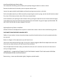
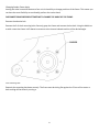
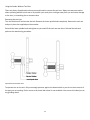
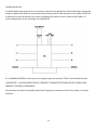
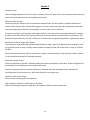
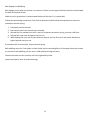
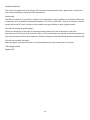
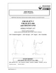
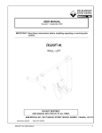
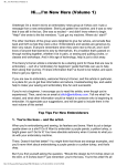
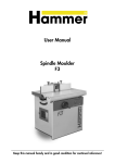
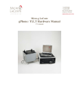
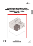
Pedestal Belt Sander
Model 248-3
USER MANUAL
Revised 07-01-14
Copyright 2014. DeBurr-It! Abrasive Tool
Division of PCE Midwest LLC. 812 Warehouse Rd. Toledo, OH 43615.
Belt sander is protected by multiple applied for patents.
1
Table of Contents:
Section 1 – Installation and Setup
Uncrating
Installation
Installing and adjusting abrasive belts
Changing sander frame angle
Changing sander direction (if
applicable)
3
4
6
8
9
Section 2 – Use
Use with tool rest
Use without tool rest
Variable speed (if applicable)
Cleaning
10
11
12
13
Section 3 – Troubleshooting
Vibration issues
Belt slippage and belt wobbling
Variable Speed Drive
Customer service contact info
14
15
16
17
2
Section 1
Uncrating
Thank you for your purchase of our 3-wheel 2x48”pedestal belt sander! Using our customer feedback and
expert engineering, we are able to provide affordable abrasive solutions in robust designs.
If you purchased your unit via the internet or mail order, your new unit will arrive expertly packed and ready
to install.
Remove all bracing from the crate and remove unit by lifting straight up from the motor side.
!!IMPORTANT!! - NEVER LIFT FROM THE SIDE COVER. This is only a protective cover and not made to lift the
weight of the sander.
Contents of the crate of the crate will be:
1x Complete Sander unit with a prewired for 115v power cable and switch (if single phase unit) or direct wired
for three phase control.
1x Precision washer
1x Warranty slip
Thoroughly check the unit for any damage and notify DeBurr-It! right away if any is found. It is important to us
our parcel service delivers your unit undamaged.
If you purchased a VFD or any control accessories, these will be in a separate box. Even if these components
were not sold directly from DeBurr-It! please inspect all items for damage.
3
Installation
ALL THREE PHASE AND VARIABLE SPEED DRIVE CONNECTIONS SHOULD BE PERFORMED BY A LICENSE
PROFESSIONAL. ALL ELECTRICAL REPAIRS SHOULD BE PERFORMED BY LICENSED PROFESSIONALS.
DEBURR-IT! ASSUMES NO RESPONSIBILITY TO ANY PROPERTY OR HUMAN BODY DAMAGES IF ANY
MODIFICATIONS ARE DONE TO THE ELECTRICAL SUPPLY. BY PURCHASING THIS UNIT AND ATTEMPTING TO
INSTALL, BUYER AGREES TO THESE TERMS.
Choose a stable stand or table to run your belt sander on. Universal pedestal stands offer the most flexibility
and allows the sander to be used to its maximum potential. If you do not have a stand picked out yet, DeBurrIt! manufactures stands for specifically for its sander.
Lag the stand firmly to the ground or attach the base of the motor securely to a heavy duty table using 5/1618 bolts, washers and lock nuts of a minimum of grade 5 hardware.
Single Phase – Plug the unit into a grounded 115v outlet. The receptacle and circuit current rating should be
rated for 15A minimum.
Three Phase – Connect the three power conductors of the whip to DOL magnetic starter with overloads sized
accordingly. Connect the ground to the ground lug.
VFD – All VFD units have three phase motors. Connect the three power conductors to the T1, T2, T3 terminals
on the drive. Connect incoming power to L1, L2, L3. A ground conductor MUST be ran from the motor to the
drive and from the drive to the building ground to reduce electrical noise. Refer to our VFD setup manual for
settings and control wiring.
4
5
Installing and Adjusting Abrasive Belts
Our unique belt tensioning system allows you to quickly change out belts in under a minute.
Remove the side knob of the safety cover to expose the belt track.
Loosen the upper spindle handle slightly to allow the spring to put tension on the belt.
Pull main handle towards you. While manually compressing the tension spring, slip the belt off the drive wheel
first, then off the bottom wheel, then off the top crowned wheel.
Install new belt by first pulling the main handle. Start by putting the new belt over the lower wheel and upper
crown wheel, then slip onto the drive wheel. Release the main handle. Snug up the upper spindle handle. DO
NOT OVER TIGHTEN OR YOU WILL DAMAGE THE UNIT.
Adjusting Runout of New or Used Belts
All belts will have to be adjusted at one point or another due to wear or due to their manufacturing process.
DISCONNECT POWER BEFORE CHANGING BELTS.
DeBurr-It! uses another in house innovative design to quickly line belts back up. No tools required and takes
just seconds.
Below is a diagram of the adjustments you will need to use.
Lockscrews should always be finger tight. If they aren’t slightly wiggle the Belt Runout Adjustment back and
forth until you take the tension of the thread of the lockscrews.
Once the adjustment has been made, your belt will track true until it stretches out too much from wear or
until you change the belt.
!!IMPORTANT!! - ALWAYS ADJUST RUNOUT WITH THE SPRINDLE HANDLE TIGHT AND ALWAYS PERFORM
RETENSIONING BEFORE ADJUSTING RUNOUT.
Retensioning – Loosen spindle handle slightly. Retighten spindle handle.
6
Runout adjustment hardware
To adjust run out loosen all three lockscrews a few turns.
All new belts and re-tensioned belts will always slightly run off the idler wheel. After changing or retensioning,
turn the Belt Runout Adjustment slightly clockwise. Turn on the sander. Adjust the Belt Runout Adjustment
until the belt is centered on the top crowned idler.
!!IMPORTANT!! – DO NOT RUN THE BELT FOR AN EXCESSIVELY LONG TIME WITH IT BIASED EXTREMELY TO
ONE SIDE OR THE OTHER OF ANY OF THE PULLEYS. DAMAGE TO RUNNING COMPONENTS AND/OR FRAME
WILL OCCUR.
While the machine is still on retighten the lockscrews finger tight. The belt is adjusted.
7
Changing Sander Frame Angle
Among the other innovative features of our unit is the ability to change positions of the frame. This means you
can have the most flexibility to comfortably perform the task at hand.
DISCONNECT POWER BEFORE ATTEMPTING TO CHANGE THE ANGLE OF THE FRAME.
Remove the abrasive belt.
Remove the 3 of the 4 mounting bolts. Securely grasp the frame and remove the last bolt. Using the babbit as
a guide, rotate the frame in 45 degree increments to the closest indexed position of the desired angle.
Lower Mounting Bolts
Reattach the mounting hardware securely. The frame must be sitting flat against the C-face of the motor or
belt tracking will be severely running o
8
Changing Belt Direction
ALL WIRING CHANGES SHOULD BE PERFORMED BY A LICENSED PROFESSIONAL. DEBURR-IT! IS NOT
RESPONSIBLE FOR ANY PROPERTY OR HUMAN BODY DAMAGES.
!!IMPORTANT!! – NEVER OPERATE THE UNIT IN WHICH THE PART COULD BE PROJECTED INTO YOUR FACE OR
ANYONE OTHER PERSON.
Wait until the unit has been turned off and has come to a complete stop. Reverse unit as appropiate for the
style of control. Restart until and pay attention to any belt adjustments that need to be made.
Single Phase – Follow directions on motor nameplate for which wires to change.
Three Phase DOL only – Swap any two phases.
Three Phase reversing control – Select the opposite direction of current rotation
VFD – Selector switch operator should be installed to reverse direction on the VFD direction input.
If equipped with foot switch control, no wiring changes will be needed at the foot switch.
Note: If your abrasive belts have a directional arrow, you may need to remove the belt and reinstall so the
direction indicated matches the direction traveled.
9
Section 2
Using with and adjusting Tool Rest
Using the sander with the tool rest makes for repeatable angles as well as a safer way to grind against an
object.
The standard tool rest adjust from 0 degrees (90 degrees perpendicular to the belt) down to 22 degrees (112
degrees relative to the belt.)
To adjust the tool rest, turn off the sander. Slightly loosen the lower spindle knob. Adjust tool rest to desired
angle. Re-tighten knob firmly before restarting the sander.
From the factory there is a 0.04” to 0.063” (1 – 1.5mm) gap between the belt and tool rest. This is too
discourage parts from being lodged between the tool rest and the belt. If the gap becomes too small, grinding
sparks may deflect against the tool rest. The the gap because too large, it becomes easier to get small parts
stuck between the tool rest and the belt. DeBurr-It! recommends replacing the tool rest of the gap increases
beyond 0.20” (5mm.)
ALWAYS WEAR EYE AND BREATHING PROTECTION WHEN USING ANY ABRASIVE TOOLS. ABRASIVE DUST IS
TOXIC TO YOUR HEALTH.
To operate sander, turn on unit. Using moderate pressure, push the work piece against the abrasive belt. Let
the piece rest on the tool rest, using your hands to guide the piece into and along the abrasive surface.
Applying too much pressure will overheat and possibly damage your workpiece.
10
Using the Sander Without Tool Rest
There are plenty of applications where you would need to remove the tool rest. Always use extreme caution
when operating without a tool rest as its possible your work piece could get away from you and cause damage
to the user, to something else or someone else.
Removing the tool rest.
Turn the machine off and remove the belt. Remove the lower spindle knob completely. Remove the tool rest
and put in place the supplied precision washer.
Reinstall the lower spindle knob and tighten as you would if the tool rest was there. Reinstall the belt and
perform the retensioning procedure.
Exploded and Assembled Views
To operate turn on the unit. Only use enough pressure against the abrasive belt so you do not loose control of
the part you are working. Easier access to the lower idler wheel is now available. You can use this wheel just as
any grinding wheel.
11
Variable Speed Drive
A variable speed drive option will let you increase or decrease the speed of the motor. We always recommend
using our supplied VFD with the correct parameters already setup for safe operation of the sander. NEVER use
a rheostat to control the speed of any single or polyphase AC induction motor. Please consult DeBurr-It!
technical department if you are using a non supplied VFD.
If no FORWARD/REVERSE control operator is supplied, jump the terminals “COM” to the desired direction.
!!IMPORTANT!! – NEVER OVERRIDE DEFAULT DEBURR-IT! PARAMETER SETTINGS WITHOUT CONSULTING
DEBURR-IT! TECHNICAL DEPARTMENT.
All parameters have been throroughly tested and changing any parameters will void any safety or warranty
conditons.
12
Cleaning
Abrasive dust can be hazardous to your health as well as other people and animals. Always wear a breathing
dust mask when sweeping up debris as well as cleaning the unit. Avoid using high pressure compressed air as
it will make this abrasive dust airborne.
Wipe down the unit will a clean soft dry cloth, such as a tshirt rag. Using low pressure compressed air (<15
psi) blow off bearings and around the drive pulley. Too much pressure could pop the dust seals off of the
bearings.
Wipe down the unit completely again with a clean rag and a mild cleaner such as Simple Green.
!!IMPORTANT!! – DO NOT WASH DOWN THE SANDER WILL RUNNING WATER.
After giving the unit a good cleaning, check all mounting bolts for tightness, as well as spindles and mounting
hardware. Tighten if necessary.
13
Section 3
Vibration Issues
Due to the high speed nature of the machine, vibration issues can arise if there are componets that have come
loose or have worn beyond their acceptable service levels.
Vibration of Drive Pulley
The drive pulley will vibrate if the set screws have become loose. The drive pulley is supplied with two set
screws locked in place with a thread locking agent. If the set screws have loosened, completely remove each
screw and apply Loctite 249 and reinstall tightly. Let the Loctite cure for 24 hours.
If vibration continues, remove wheel and inspect the bore. Using a precision measuring instrument, measure
the bore of the drive wheel. Check the bore diameter at serveral points around the bore circumference. The
maximum allowed diameter is 0.628” (15.95mm). If the bore has enlargened beyond this, replace drive wheel.
Vibration of Lower or Upper Idler Wheels
First make sure upper and lower spindle handles/knobs are tight. Inspect the tightness of each spindle screw.
If any spindle screw is loose, carefully remove spindle and apply Loctite 249 and reinstall. Torque to 21 ft/lbs
(30 Nm.)
Remove belt and check each idler by hand for any rough or broken bearings. If any bearing is broken, DeBurrIt! will reload the bearings for free under warranty.
Vibration of Upper Frame
Check the tightness of the two ¼-20 bolts holding the tensioner assembly to the frame. Check the tightness of
the shoulder screw holding the main handle to the frame.
Check the integrity of the two urethane washers in between the lower and upper frame. Reinstall the
mounting bolts to so the nylon nut is flush with the end of mounting screw.
Vibration of the Lower Frame
Check the four mounting bolts for tightness.
High Frequency Vibration on Work Rest or Belt Rest
Check all mounting hardware for tightness. Check gusset welds for cracks on belt rest.
14
Belt Slippage and Wobbling
Belt slippage occurs when the tension is too loose or if there is some type of lubricant that has contaminated
the back of the abrasive belt.
Make sure oil or grease hasn’t contaminated the back of the belt. If so, replace belt.
Follow the retensioning proceedure. If this fails to retension the belt follow the steps below to reset the
preload on the main spring.
1.
2.
3.
4.
5.
Completely remove the belt.
Remove bolt nuts from the tensioner assembly.
Reinstall the first standard nut until it starts to compress the tension spring, continue a half turn.
Reinstall the nylon lock nut against the first nut.
While holding the nylon nut in place with one wrench, turn the first nut in the loosen direction to
tighten against the nylon nut.
If procedure fails to tension belt, replace tension spring.
Belt wobbling can occur if the upper or lower frame are not secured tightly or if the upper frame lock screws
are too loose. Belt wobbling can also occur if idler pulleys bearings are worn.
Check lock screws to make sure they are firmly tightened by hand.
Inspect bearings for worn or broken bearings.
15
Variable Speed Drive
This covers only operational isses with the VFD. For technical issues with the unit, please refer to the factory
user manual provided to you by the VFD manufacturers.
Overheating
The VFD can overheat if it is placed in a position of extreme heat or lack of sufficient air circulation. Make sure
to keep the unit in an ambient temperature between +15F (-9C) to +105F (40C.) If the VFD overheats, stop the
sander and let the VFD cool. Provide a cooler ambient running conditions or stop using the sander.
Unit will not respond to speed changes
Check the connections on the back of the potentiometer and on the input connections on the drive.
Potentiometer is 10k ohm max of resistance. Refer to VFD manufacturer user manual and check parameters to
view minimum and maximum set frequencies. Minimum frequency should be 30 and maximum should be 100.
Unit will not start with foot pedal
Refer to diagram and check connections inside foot pedal and on input connections of the drive.
VFD tripping breaker
Replace VFD.
16
Customer Serivce Contacts
Office Phone:
419-913-1966
Email:
[email protected]
Please include the model number, serial number, and a short summary of the problem you are
having. We will contact you as soon as possible.
Our website is always being updated with technical documents and video procedure. Please visit it often for
updates.
www.deburrit.com
17